EP3805888A1 - Remote operation system for forklift - Google Patents
Remote operation system for forklift Download PDFInfo
- Publication number
- EP3805888A1 EP3805888A1 EP19807443.7A EP19807443A EP3805888A1 EP 3805888 A1 EP3805888 A1 EP 3805888A1 EP 19807443 A EP19807443 A EP 19807443A EP 3805888 A1 EP3805888 A1 EP 3805888A1
- Authority
- EP
- European Patent Office
- Prior art keywords
- pallet
- forklift
- remote operation
- truck
- display
- Prior art date
- Legal status (The legal status is an assumption and is not a legal conclusion. Google has not performed a legal analysis and makes no representation as to the accuracy of the status listed.)
- Granted
Links
Images



Classifications
-
- G—PHYSICS
- G05—CONTROLLING; REGULATING
- G05D—SYSTEMS FOR CONTROLLING OR REGULATING NON-ELECTRIC VARIABLES
- G05D1/00—Control of position, course, altitude or attitude of land, water, air or space vehicles, e.g. using automatic pilots
- G05D1/0011—Control of position, course, altitude or attitude of land, water, air or space vehicles, e.g. using automatic pilots associated with a remote control arrangement
- G05D1/0038—Control of position, course, altitude or attitude of land, water, air or space vehicles, e.g. using automatic pilots associated with a remote control arrangement by providing the operator with simple or augmented images from one or more cameras located onboard the vehicle, e.g. tele-operation
-
- B—PERFORMING OPERATIONS; TRANSPORTING
- B66—HOISTING; LIFTING; HAULING
- B66F—HOISTING, LIFTING, HAULING OR PUSHING, NOT OTHERWISE PROVIDED FOR, e.g. DEVICES WHICH APPLY A LIFTING OR PUSHING FORCE DIRECTLY TO THE SURFACE OF A LOAD
- B66F9/00—Devices for lifting or lowering bulky or heavy goods for loading or unloading purposes
- B66F9/06—Devices for lifting or lowering bulky or heavy goods for loading or unloading purposes movable, with their loads, on wheels or the like, e.g. fork-lift trucks
- B66F9/063—Automatically guided
-
- G—PHYSICS
- G05—CONTROLLING; REGULATING
- G05D—SYSTEMS FOR CONTROLLING OR REGULATING NON-ELECTRIC VARIABLES
- G05D1/00—Control of position, course, altitude or attitude of land, water, air or space vehicles, e.g. using automatic pilots
- G05D1/02—Control of position or course in two dimensions
- G05D1/021—Control of position or course in two dimensions specially adapted to land vehicles
- G05D1/0212—Control of position or course in two dimensions specially adapted to land vehicles with means for defining a desired trajectory
-
- G—PHYSICS
- G05—CONTROLLING; REGULATING
- G05D—SYSTEMS FOR CONTROLLING OR REGULATING NON-ELECTRIC VARIABLES
- G05D1/00—Control of position, course, altitude or attitude of land, water, air or space vehicles, e.g. using automatic pilots
- G05D1/20—Control system inputs
- G05D1/22—Command input arrangements
- G05D1/221—Remote-control arrangements
- G05D1/222—Remote-control arrangements operated by humans
- G05D1/224—Output arrangements on the remote controller, e.g. displays, haptics or speakers
-
- G—PHYSICS
- G05—CONTROLLING; REGULATING
- G05D—SYSTEMS FOR CONTROLLING OR REGULATING NON-ELECTRIC VARIABLES
- G05D1/00—Control of position, course, altitude or attitude of land, water, air or space vehicles, e.g. using automatic pilots
- G05D1/60—Intended control result
- G05D1/646—Following a predefined trajectory, e.g. a line marked on the floor or a flight path
-
- G—PHYSICS
- G06—COMPUTING OR CALCULATING; COUNTING
- G06V—IMAGE OR VIDEO RECOGNITION OR UNDERSTANDING
- G06V20/00—Scenes; Scene-specific elements
- G06V20/50—Context or environment of the image
- G06V20/56—Context or environment of the image exterior to a vehicle by using sensors mounted on the vehicle
-
- H—ELECTRICITY
- H04—ELECTRIC COMMUNICATION TECHNIQUE
- H04N—PICTORIAL COMMUNICATION, e.g. TELEVISION
- H04N7/00—Television systems
- H04N7/18—Closed-circuit television [CCTV] systems, i.e. systems in which the video signal is not broadcast
- H04N7/183—Closed-circuit television [CCTV] systems, i.e. systems in which the video signal is not broadcast for receiving images from a single remote source
Definitions
- the travel controller further controls the display to display an enlargement of an area around the selected pallet on a sub-screen.
- a rack 50 is installed in the workplace.
- the rack 50 allows pallets (51-58) and items W to be placed on two shelves of the rack 50. That is, one item W is placed on the pallet 51 on the bottom shelf, and above it, another item W is placed on the pallet 52 on the top shelf. Next to it, one item W is placed on the pallet 53 on the bottom shelf, and above it, another item W is placed on the pallet 54 on the top shelf. Next to it, one item W is placed on the pallet 55 on the bottom shelf, and above it, another item W is placed on the pallet 56 on the top shelf. Next to it, one item W is placed on the pallet 57 on the bottom shelf, and above it, another item W is placed on the pallet 58 on the top shelf. In this arrangement, an operator remotely controls the forklift truck 20 to pick up an item.
- the remote operation device 40 includes a wireless communicator 41 that serves as an operation device communication part, a controller 42, an operating part 43, a display 44, and an image signal processor 45.
- the operating part 43 adopts an operation system, such as the touch screen system, the mouse system, or the joystick system.
- the controller 42 that serves as a pallet detector is configured to perform, by using the image signal processor 45, image recognition processing of the image captured by the camera 33 and detect the plurality of pallets 51-58.
- the controller 42 that serves as a display controller is configured to control the display 44 to display the image captured by the camera 33 with an indication for pallet selection from the detected pallets 51-58.
- the controller 42 that serves as a travel controller is configured to control the forklift truck 20 to move to a position of the selected pallet.
- pallet detection is performed through image recognition processing, and boxes for pallet selection are popped up. Then, a transition to automatic control by the travel controller is performed when a box, which corresponds to a pallet to be worked, is selected by the operator. Then, the forklift truck automatically moves so as to face the pallet, and automatically inserts the fork into the pallet holes after confirmation of the positions of the pallet holes.
Landscapes
- Engineering & Computer Science (AREA)
- Remote Sensing (AREA)
- Radar, Positioning & Navigation (AREA)
- Physics & Mathematics (AREA)
- General Physics & Mathematics (AREA)
- Automation & Control Theory (AREA)
- Aviation & Aerospace Engineering (AREA)
- Multimedia (AREA)
- Structural Engineering (AREA)
- Transportation (AREA)
- Signal Processing (AREA)
- Life Sciences & Earth Sciences (AREA)
- Geology (AREA)
- Mechanical Engineering (AREA)
- Civil Engineering (AREA)
- Theoretical Computer Science (AREA)
- Forklifts And Lifting Vehicles (AREA)
- Control Of Position, Course, Altitude, Or Attitude Of Moving Bodies (AREA)
- Closed-Circuit Television Systems (AREA)
Abstract
Description
- The present invention relates to a forklift-truck remote operation system.
- A forklift truck may include a camera to grasp an environment around the forklift truck (for example, Patent literature 1).
- Patent literature 1: Japanese Patent Application Publication No.
2014-11518 - In the forklift-truck remote operation system, an operator operates a forklift truck to which a camera is mounted while watching a screen, but it is difficult to move the forklift truck to a position of a pallet.
- The present invention is directed to providing a forklift-truck remote operation system that facilitates movement of a forklift truck to a position of a desired pallet.
- In the invention according to claim 1, a forklift-truck remote operation system includes a forklift truck including a vehicle communication part; and a remote operation device including an operation device communication part that is configured to communicate wirelessly with the vehicle communication part and used for remote operation of the forklift truck, wherein the forklift-truck remote operation system includes a camera mounted to the forklift truck and configured to capture an image of an area around the forklift truck; a display disposed in the remote operation device and configured to display the image captured by the camera; a pallet detector configured to perform image recognition processing of the image captured by the camera and detect a plurality of pallets; a display controller configured to control the display to display the image captured by the camera with an indication for pallet selection from the pallets detected by the pallet detector; and a travel controller configured to control the forklift truck to move to a position of the selected pallet.
- In the invention according to claim 1, the plurality of pallets is detected through image recognition processing of the image captured by the camera, the image captured by the camera is displayed by the display, with the indication for pallet selection from the detected pallets, and the forklift truck moves to a position of a selected pallet. This facilitates the movement of the forklift truck to a position of a desired pallet.
- As described in claim 2, in the forklift-truck remote operation system according to claim 1, the indication for pallet selection may include pop-up boxes corresponding to the respective detected pallets.
- As described in claim 3, in the forklift-truck remote operation system according to claim 1, the indication for pallet selection may include highlighting of outlines of the detected pallets.
- As described in claim 4, in the forklift-truck remote operation system according to any one of claims 1 to 3, the travel controller further controls the display to display an enlargement of an area around the selected pallet on a sub-screen.
- The present invention facilitates movement of a forklift truck to a position of a desired pallet.
-
- FIG. 1 is a schematic view of a forklift-truck remote operation system.
- FIG. 2 is a schematic view for explaining a situation where a forklift truck and pallets are in a workplace.
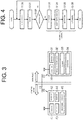
- FIG. 3 is a block diagram of an electrical configuration of the forklift-truck remote operation system.
- FIG. 4 is a flowchart for explaining an operation.
- FIG. 5 is a view of a displayed screen image for explanation of the operation.
- FIGS. 6A and 6B are schematic plan views that explain the operation.
- FIG. 7 is a view of a displayed screen image.
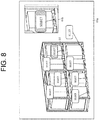
- FIG. 8 is a view of a displayed screen image.
- The following describes an embodiment of the present invention with reference to the drawings.
- As shown in
FIG. 1 , a forklift-truckremote operation system 10 includes aforklift truck 20 and aremote operation device 40 used for remote operation of theforklift truck 20. Theforklift truck 20 is placed in a workplace. Theremote operation device 40 is disposed in a control room. Theremote operation device 40 is used in the control room to remotely control theforklift truck 20 in the workplace. - As shown in
FIG. 2 , arack 50 is installed in the workplace. Therack 50 allows pallets (51-58) and items W to be placed on two shelves of therack 50. That is, one item W is placed on thepallet 51 on the bottom shelf, and above it, another item W is placed on thepallet 52 on the top shelf. Next to it, one item W is placed on thepallet 53 on the bottom shelf, and above it, another item W is placed on thepallet 54 on the top shelf. Next to it, one item W is placed on thepallet 55 on the bottom shelf, and above it, another item W is placed on thepallet 56 on the top shelf. Next to it, one item W is placed on thepallet 57 on the bottom shelf, and above it, another item W is placed on thepallet 58 on the top shelf. In this arrangement, an operator remotely controls theforklift truck 20 to pick up an item. - In
FIG. 2 , each of the pallets 51-58 has fork insertion holes, and a fork is inserted into the fork insertion holes. - As shown in
FIG. 1 , theforklift truck 20 includeswheels 22 on the front and the rear of abody 21. Thebody 21 includes aloading device 23. Theloading device 23 performs item loading or unloading. - The
loading device 23 includes amast 24, abracket 25, and afork 26. Thefork 26 is disposed on themast 24 via thebracket 25 such that thefork 26 is movable in the up-down direction. In this embodiment, theforklift truck 20 is configured such that a driver can operate theforklift truck 20 while sitting, but theforklift truck 20 may be a driverless forklift truck not including a driver seat. - Further, the
forklift truck 20 may be an engine forklift truck including an engine, an electric forklift truck including a power storage device and an electric motor, or a fuel cell forklift truck including a fuel cell and an electric motor. Alternatively, theforklift truck 20 may be a hybrid forklift truck including an engine, a power storage device, and an electric motor. - As shown in
FIG. 3 , theforklift truck 20 includes awireless communicator 30 that serves as a vehicle communication part, acontroller 31, animage signal processor 32, acamera 33, and anactuator 34. Thecamera 33 is mounted to theforklift truck 20 and configured to capture an image of an area around theforklift truck 20. Specifically, thecamera 33 is attached to thebracket 25 and captures an image of a front view in a travelling direction of theforklift truck 20. Theactuator 34 includes a travelling actuator and a loading actuator, and the loading actuator includes a tilting actuator and an elevating actuator. The travelling actuator steers and rotates thewheels 22. - The
remote operation device 40 includes awireless communicator 41 that serves as an operation device communication part, acontroller 42, anoperating part 43, adisplay 44, and animage signal processor 45. Theoperating part 43 adopts an operation system, such as the touch screen system, the mouse system, or the joystick system. - The
wireless communicator 41 is capable of communicating wirelessly with thewireless communicator 30 of theforklift truck 20. That is, thewireless communicator 30 of theforklift truck 20 and thewireless communicator 41 of theremote operation device 40 are capable of communicating with each other. - When the operator performs a desired operation with the
operating part 43 of theremote operation device 40, thecontroller 42 sends operation information to theforklift truck 20 via thewireless communicator 41. Thewireless communicator 30 of theforklift truck 20 receives the operation information sent from theremote operation device 40, and thecontroller 31 activates theactuator 34 to perform a desired operation. - In contrast, the
controller 31 of theforklift truck 20 sends an image captured by thecamera 33 to theremote operation device 40 via theimage signal processor 32 and thewireless communicator 30. Thewireless communicator 41 of theremote operation device 40 receives the camera image sent from theforklift truck 20, and thecontroller 42 controls thedisplay 44, via theimage signal processor 45, to display the image. That is, thedisplay 44 disposed in theremote operation device 40 is configured to display the image captured by thecamera 33. The operator performs an operation while watching the image captured by thecamera 33 on thedisplay 44. - The forklift-truck
remote operation system 10 has a function for automatic control of theforklift truck 20. This automatic control function enables loading operation. Specifically, as shown inFIG. 6A , theforklift truck 20 is automatically controlled to approach a pallet selected by the operator, and as shown inFIG. 6B , theforklift truck 20 is automatically controlled to adjust its position so as to face the pallet, insert a fork into pallet holes, or lift the fork inserted into the pallet holes. - In
FIG. 3 , thecontroller 42 that serves as a pallet detector is configured to perform, by using theimage signal processor 45, image recognition processing of the image captured by thecamera 33 and detect the plurality of pallets 51-58. Thecontroller 42 that serves as a display controller is configured to control thedisplay 44 to display the image captured by thecamera 33 with an indication for pallet selection from the detected pallets 51-58. Thecontroller 42 that serves as a travel controller is configured to control theforklift truck 20 to move to a position of the selected pallet. - Next, the operation will be explained.
- As shown in
FIG. 4 , thecontroller 42 of theremote operation device 40 performs image recognition and detects pallets on a screen in step S100. For example, the pallets are detected through image recognition of a pallet shape (a pallet outline, a pallet hole shape, and the like) from a camera image. In step S101, thecontroller 42 pops up selection boxes on the respective detected pallets. This makes it easy for an operator to select an item to be picked up. - Further, the
controller 42 determines in step S102 whether a pallet to be worked has been selected by the operator, and thecontroller 42 makes a return to step S101 for detection of the pallets on the screen if any pallet has not been selected, and pops up the selection boxes on the respective detected pallets in step S101. That is, boxes respectively corresponding to the detected pallets are popped up. - After a pallet to be worked is selected by the operator from the detected pallets in step S102, the
controller 42 makes a transition to step S103, and as the travel controller, controls theforklift truck 20 to approach the target pallet through automatic control in step S103, and adjusts a position of theforklift truck 20 in step S104 so that theforklift truck 20 faces the pallet. Further, thecontroller 42 performs control to insert thefork 26 into holes of the pallet in step S105 so that the pallet is lifted up in step S106. -
FIG. 5 shows information displayed on ascreen 44a of thedisplay 44. - In
FIG. 5 , thedisplay 44 displays an image captured by thecamera 33. Further, when the pallets are detected through processing in step S100 inFIG. 4 , the selection boxes are popped up on the pallets detected through processing in step S101. Specifically, boxes indicating "select" are popped up corresponding to the respective detected pallets. - Then, the operator selects a pallet. For example, the operator moves the cursor to a box that corresponds to a pallet to be worked, and clicks it. For example, when the operator selects the box corresponding to the
pallet 58, the box is colored and theforklift truck 20 drawn with a solid line inFIG. 6A is controlled to approach thepallet 58 as indicated with a dashed dotted line by the travel controller through automatic control. As shown inFIG. 6B , theforklift truck 20 then faces thepallet 58. After that, thepallet 58 is lifted up by thefork 26 inserted intoholes 58a of thepallet 58. - In such a way, pallet detection is performed through image recognition processing, and boxes for pallet selection are popped up. Then, a transition to automatic control by the travel controller is performed when a box, which corresponds to a pallet to be worked, is selected by the operator. Then, the forklift truck automatically moves so as to face the pallet, and automatically inserts the fork into the pallet holes after confirmation of the positions of the pallet holes.
- That is, a transition to automatic control by the travel controller is performed when boxes for pallet selection are popped up and a pallet to be worked is selected by an operator after pallets on a screen are detected through image recognition.
- Accordingly, pallet selection is difficult if a plurality of pallets is placed in the vicinity, but the box pop-up enables safe pallet selection. Further, the box pop-up enables pallet recognition in an early stage.
- More details are explained.
- When a forklift-truck remote operation system, wherein a camera is mounted to a body, is operated by an operator watching a screen (image), it is difficult to move the forklift truck to a position of a pallet or insert a fork into pallet holes. That is, when a camera is mounted to a forklift truck and remote operation is performed by an operator watching an image, it is difficult (it takes time) to move the forklift truck to a position of a pallet to be worked. Further, when the operator controls the forklift truck while watching the image, it is difficult (it takes time) to insert a fork into pallet holes. Accordingly, it is difficult to select a pallet to which an item is carried just by watching a camera image.
- In this embodiment, detecting pallets through image recognition of a camera image and popping up boxes for pallet selection from the detected pallets facilitate pallet selection, travel to a pallet, movement to a pallet position, and fork insertion into pallet holes. That is, it does not only allow remote operation of a forklift truck by an operator watching an image of a camera mounted to the forklift truck, but facilitates movement of the forklift truck to a position of a pallet to be worked, so that time is reduced. Further, it does not only allow the operation by the operator watching the image, but facilitates fork insertion into holes of a pallet to be worked, so that time is reduced.
- In
FIG. 4 , the process from the operation of approaching the target pallet in step S103 to the operation of lifting the pallet in step S106 is fully automated, but a task of automatic control (operation in each step) can be selected; for example, the step of fork insertion into pallet holes and subsequent steps may be performed by the operator while only the operation of approaching the target pallet is automated. - According to the aforementioned embodiment, the following effects can be achieved.
- (1) The forklift-truck
remote operation system 10 includes theforklift truck 20, which includes thewireless communicator 30 as a vehicle communication part, and theremote operation device 40, which includes thewireless communicator 41 as an operation device communication part that is configured to communicate wirelessly with thewireless communicator 30 as a vehicle communication part and is used for remote control of theforklift truck 20. The forklift-truckremote operation system 10 includes thecamera 33 that is mounted to theforklift truck 20 and captures an image of an area around theforklift truck 20, thedisplay 44 that is disposed in theremote operation device 40 and displays the image captured by thecamera 33, and thecontroller 42. Thecontroller 42 as a pallet detector performs image recognition processing of the image captured by thecamera 33 and detects the plurality of pallets 51-58. Thecontroller 42 as a display controller controls thedisplay 44 to display the image captured by thecamera 33 with an indication for pallet selection from the detected pallets. Thecontroller 42 as a travel controller performs movement to a position of the selected pallet.
Accordingly, the plurality of pallets 51-58 is detected through image recognition processing of the image captured by thecamera 33, and the image captured by thecamera 33 is displayed on thedisplay 44 with the indication for pallet selection from the detected pallets, so that the movement to the position of the selected pallet is performed. This facilitates the movement to a position of a desired pallet. - (2) The pop-up boxes that correspond to the respective detected pallets serve as an indication for pallet selection, so that pallet selection is facilitated.
The embodiment is not limited to the aforementioned embodiment, and may be embodied as follows.- ∘ The processing in
FIG. 4 is performed by thecontroller 42 of theremote operation device 40 but may be performed by thecontroller 31 of theforklift truck 20. - ∘ The
camera 33 may capture an image of any area, other than the front area from theforklift truck 20, such as the rear area from theforklift truck 20 in the traveling direction. - ∘ The shapes of the boxes as an indication for pallet selection may be any shape that facilitates selection by the operator.
- ∘ The indication for pallet selection may include any emphasis indication, other than pop-up, such as enlargement. Further, as shown in
FIG. 7 , the outline of an image-recognized pallet may be highlighted. In this case, the target pallet is selected by clicking the highlighted outline of a pallet to be worked. Specifically, inFIG. 7 , the outlines of the detected pallets 51-58 are emphasized with a thick line, and the outline of the selectedpallet 58 is further emphasized, for example, with a line thicker than the thick line. In such a way, the indication for pallet selection may include highlighting of the outlines of the detected pallets. - ∘ To facilitate identification of the pallet selected by the operator, for example, as shown in
FIG. 8 , a function to enlarge an area around the selected pallet on a sub-screen may be included. Specifically, inFIG. 8 , the area around the selectedpallet 58 is enlarged on a sub-screen 44b within thescreen 44a. In such a way, thecontroller 42 as a travel controller may further control thedisplay 44 to display an enlargement of the area around the selected pallet as a sub-screen. Further, the boxes may change shapes when selected.
- ∘ The processing in
-
- 10 forklift-truck remote operation system
- 20 forklift truck
- 30 wireless communicator
- 31 controller
- 33 camera
- 40 remote operation device
- 41 wireless communicator
- 42 controller
- 44 display
- 51-58 pallet
Claims (4)
- A forklift-truck remote operation system comprising:a forklift truck including a vehicle communication part; anda remote operation device including an operation device communication part that is configured to communicate wirelessly with the vehicle communication part and used for remote operation of the forklift truck, whereinthe forklift-truck remote operation system includes:a camera mounted to the forklift truck and configured to capture an image of an area around the forklift truck;a display disposed in the remote operation device and configured to display the image captured by the camera;a pallet detector configured to perform image recognition processing of the image captured by the camera and detect a plurality of pallets;a display controller configured to control the display to display the image captured by the camera with an indication for pallet selection from the pallets detected by the pallet detector; anda travel controller configured to control the forklift truck to move to a position of the selected pallet.
- The forklift-truck remote operation system according to claim 1, wherein the indication for pallet selection includes pop-up boxes corresponding to the respective detected pallets.
- The forklift-truck remote operation system according to claim 1, wherein the indication for pallet selection includes highlighting of outlines of the detected pallets.
- The forklift-truck remote operation system according to any one of claims 1 to 3, wherein the travel controller further controls the display to display an enlargement of an area around the selected pallet on a sub-screen.
Applications Claiming Priority (2)
| Application Number | Priority Date | Filing Date | Title |
|---|---|---|---|
| JP2018099843A JP6922848B2 (en) | 2018-05-24 | 2018-05-24 | Remote control system for forklifts |
| PCT/JP2019/019026 WO2019225390A1 (en) | 2018-05-24 | 2019-05-14 | Remote operation system for forklift |
Publications (3)
| Publication Number | Publication Date |
|---|---|
| EP3805888A1 true EP3805888A1 (en) | 2021-04-14 |
| EP3805888A4 EP3805888A4 (en) | 2021-06-16 |
| EP3805888B1 EP3805888B1 (en) | 2022-06-01 |
Family
ID=68617062
Family Applications (1)
| Application Number | Title | Priority Date | Filing Date |
|---|---|---|---|
| EP19807443.7A Active EP3805888B1 (en) | 2018-05-24 | 2019-05-14 | Remote operation system for forklift |
Country Status (4)
| Country | Link |
|---|---|
| US (1) | US11939197B2 (en) |
| EP (1) | EP3805888B1 (en) |
| JP (1) | JP6922848B2 (en) |
| WO (1) | WO2019225390A1 (en) |
Cited By (1)
| Publication number | Priority date | Publication date | Assignee | Title |
|---|---|---|---|---|
| IT202200026451A1 (en) * | 2022-12-22 | 2024-06-22 | Toyota Mat Handling Manufacturing Italy S P A | Load anomaly recognition |
Families Citing this family (3)
| Publication number | Priority date | Publication date | Assignee | Title |
|---|---|---|---|---|
| JP7342798B2 (en) * | 2020-06-05 | 2023-09-12 | 株式会社豊田自動織機 | Self-driving forklift monitoring system and self-driving forklift monitoring method |
| JP7456368B2 (en) * | 2020-12-21 | 2024-03-27 | 株式会社豊田自動織機 | Forklift work support equipment |
| JP7775779B2 (en) * | 2022-04-28 | 2025-11-26 | 株式会社豊田自動織機 | Cargo Handling System |
Family Cites Families (13)
| Publication number | Priority date | Publication date | Assignee | Title |
|---|---|---|---|---|
| JPS59182198A (en) * | 1983-03-29 | 1984-10-16 | 日揮株式会社 | Remote control forklift assisting system |
| US5208753A (en) * | 1991-03-28 | 1993-05-04 | Acuff Dallas W | Forklift alignment system |
| US8192137B2 (en) * | 2004-05-03 | 2012-06-05 | Jervis B. Webb Company | Automatic transport loading system and method |
| US10600256B2 (en) * | 2006-12-13 | 2020-03-24 | Crown Equipment Corporation | Impact sensing usable with fleet management system |
| TW200849102A (en) * | 2007-06-01 | 2008-12-16 | Murata Machinery Ltd | Inspection system and inspection method |
| JP2009301175A (en) * | 2008-06-11 | 2009-12-24 | Ihi Aerospace Co Ltd | Monitoring method |
| JP6008612B2 (en) | 2012-06-28 | 2016-10-19 | 三菱重工業株式会社 | Wirelessly operated vehicle remote control system |
| JP2015225450A (en) * | 2014-05-27 | 2015-12-14 | 村田機械株式会社 | Autonomous traveling vehicle, and object recognition method in autonomous traveling vehicle |
| EP3060966B1 (en) * | 2014-07-30 | 2021-05-05 | SZ DJI Technology Co., Ltd. | Systems and methods for target tracking |
| JP6614607B2 (en) * | 2015-07-09 | 2019-12-04 | 株式会社Ihiエアロスペース | Remote control system and method |
| DE102015113132A1 (en) * | 2015-08-10 | 2017-02-16 | Linde Material Handling Gmbh | Method for driver assistance with an industrial truck |
| JP6492024B2 (en) * | 2016-03-30 | 2019-03-27 | 株式会社豊田中央研究所 | Moving body |
| JP6739299B2 (en) * | 2016-09-13 | 2020-08-12 | 株式会社日立製作所 | Transport system and transport method |
-
2018
- 2018-05-24 JP JP2018099843A patent/JP6922848B2/en not_active Expired - Fee Related
-
2019
- 2019-05-14 WO PCT/JP2019/019026 patent/WO2019225390A1/en not_active Ceased
- 2019-05-14 EP EP19807443.7A patent/EP3805888B1/en active Active
- 2019-05-14 US US17/055,305 patent/US11939197B2/en active Active
Cited By (2)
| Publication number | Priority date | Publication date | Assignee | Title |
|---|---|---|---|---|
| IT202200026451A1 (en) * | 2022-12-22 | 2024-06-22 | Toyota Mat Handling Manufacturing Italy S P A | Load anomaly recognition |
| EP4389681A1 (en) * | 2022-12-22 | 2024-06-26 | TOYOTA MATERIAL HANDLING MANUFACTURING ITALY S.p.A | Load anomaly recognition |
Also Published As
| Publication number | Publication date |
|---|---|
| EP3805888A4 (en) | 2021-06-16 |
| US20210171329A1 (en) | 2021-06-10 |
| JP2019204353A (en) | 2019-11-28 |
| WO2019225390A1 (en) | 2019-11-28 |
| US11939197B2 (en) | 2024-03-26 |
| JP6922848B2 (en) | 2021-08-18 |
| EP3805888B1 (en) | 2022-06-01 |
Similar Documents
| Publication | Publication Date | Title |
|---|---|---|
| EP3805888B1 (en) | Remote operation system for forklift | |
| EP3000772B1 (en) | Fork-lift truck and method for operating a fork-lift truck | |
| EP3000771B1 (en) | Fork-lift truck | |
| EP2527288B1 (en) | Fork lift truck with automatic lift height control | |
| US11524881B2 (en) | Industrial vehicle remote operation system, remote operation device, computer-readable storage medium storing industrial vehicle remote operation program, industrial vehicle remote operation method, and industrial vehicle | |
| WO2020039817A1 (en) | Loading operation assistance device for forklift | |
| JP7268575B2 (en) | Operation support device for cargo handling vehicle | |
| EP4290458B1 (en) | Device determination system, device determination method, and device determination program | |
| JP2020132431A (en) | Travel support device for industrial vehicle | |
| WO2021066138A1 (en) | Operation assistance device for cargo handling vehicle | |
| FI3153348T4 (en) | Load transport vehicle with monitoring means for secure handling of a swappable container | |
| WO2020049897A1 (en) | Remote control system for forklift | |
| JP2011037536A (en) | Fork-lift truck | |
| WO2020095602A1 (en) | Remote operating system for forklift | |
| JP7544649B2 (en) | Cargo Handling System | |
| JP2020066505A (en) | Remote operation system of forklift | |
| JP7267850B2 (en) | Operation terminal, mobile system, and display method | |
| US20230331527A1 (en) | Control device for industrial vehicle, control system for industrial vehicle, and program for control device for industrial vehicle | |
| JP7087737B2 (en) | Remote control system for forklifts | |
| EP3579076B1 (en) | Tracking vehicle control system | |
| JP2020128270A (en) | Cargo handling support system | |
| EP3981732A1 (en) | Industrial truck with improved display function | |
| JP2019034801A (en) | Conveying system | |
| JP2020007058A (en) | Remote operation system for forklift | |
| CN113798334A (en) | Automatic control method for pusher |
Legal Events
| Date | Code | Title | Description |
|---|---|---|---|
| STAA | Information on the status of an ep patent application or granted ep patent |
Free format text: STATUS: THE INTERNATIONAL PUBLICATION HAS BEEN MADE |
|
| PUAI | Public reference made under article 153(3) epc to a published international application that has entered the european phase |
Free format text: ORIGINAL CODE: 0009012 |
|
| STAA | Information on the status of an ep patent application or granted ep patent |
Free format text: STATUS: REQUEST FOR EXAMINATION WAS MADE |
|
| 17P | Request for examination filed |
Effective date: 20201120 |
|
| AK | Designated contracting states |
Kind code of ref document: A1 Designated state(s): AL AT BE BG CH CY CZ DE DK EE ES FI FR GB GR HR HU IE IS IT LI LT LU LV MC MK MT NL NO PL PT RO RS SE SI SK SM TR |
|
| AX | Request for extension of the european patent |
Extension state: BA ME |
|
| A4 | Supplementary search report drawn up and despatched |
Effective date: 20210514 |
|
| RIC1 | Information provided on ipc code assigned before grant |
Ipc: G05D 1/00 20060101AFI20210508BHEP Ipc: B66F 9/24 20060101ALI20210508BHEP Ipc: H04N 7/18 20060101ALI20210508BHEP |
|
| DAV | Request for validation of the european patent (deleted) | ||
| DAX | Request for extension of the european patent (deleted) | ||
| GRAP | Despatch of communication of intention to grant a patent |
Free format text: ORIGINAL CODE: EPIDOSNIGR1 |
|
| STAA | Information on the status of an ep patent application or granted ep patent |
Free format text: STATUS: GRANT OF PATENT IS INTENDED |
|
| INTG | Intention to grant announced |
Effective date: 20211214 |
|
| GRAS | Grant fee paid |
Free format text: ORIGINAL CODE: EPIDOSNIGR3 |
|
| GRAA | (expected) grant |
Free format text: ORIGINAL CODE: 0009210 |
|
| STAA | Information on the status of an ep patent application or granted ep patent |
Free format text: STATUS: THE PATENT HAS BEEN GRANTED |
|
| AK | Designated contracting states |
Kind code of ref document: B1 Designated state(s): AL AT BE BG CH CY CZ DE DK EE ES FI FR GB GR HR HU IE IS IT LI LT LU LV MC MK MT NL NO PL PT RO RS SE SI SK SM TR |
|
| REG | Reference to a national code |
Ref country code: GB Ref legal event code: FG4D |
|
| REG | Reference to a national code |
Ref country code: AT Ref legal event code: REF Ref document number: 1495829 Country of ref document: AT Kind code of ref document: T Effective date: 20220615 Ref country code: CH Ref legal event code: EP |
|
| REG | Reference to a national code |
Ref country code: IE Ref legal event code: FG4D |
|
| REG | Reference to a national code |
Ref country code: DE Ref legal event code: R096 Ref document number: 602019015498 Country of ref document: DE |
|
| REG | Reference to a national code |
Ref country code: SE Ref legal event code: TRGR |
|
| REG | Reference to a national code |
Ref country code: LT Ref legal event code: MG9D |
|
| REG | Reference to a national code |
Ref country code: NL Ref legal event code: MP Effective date: 20220601 |
|
| PG25 | Lapsed in a contracting state [announced via postgrant information from national office to epo] |
Ref country code: NO Free format text: LAPSE BECAUSE OF FAILURE TO SUBMIT A TRANSLATION OF THE DESCRIPTION OR TO PAY THE FEE WITHIN THE PRESCRIBED TIME-LIMIT Effective date: 20220901 Ref country code: LT Free format text: LAPSE BECAUSE OF FAILURE TO SUBMIT A TRANSLATION OF THE DESCRIPTION OR TO PAY THE FEE WITHIN THE PRESCRIBED TIME-LIMIT Effective date: 20220601 Ref country code: HR Free format text: LAPSE BECAUSE OF FAILURE TO SUBMIT A TRANSLATION OF THE DESCRIPTION OR TO PAY THE FEE WITHIN THE PRESCRIBED TIME-LIMIT Effective date: 20220601 Ref country code: GR Free format text: LAPSE BECAUSE OF FAILURE TO SUBMIT A TRANSLATION OF THE DESCRIPTION OR TO PAY THE FEE WITHIN THE PRESCRIBED TIME-LIMIT Effective date: 20220902 Ref country code: FI Free format text: LAPSE BECAUSE OF FAILURE TO SUBMIT A TRANSLATION OF THE DESCRIPTION OR TO PAY THE FEE WITHIN THE PRESCRIBED TIME-LIMIT Effective date: 20220601 Ref country code: BG Free format text: LAPSE BECAUSE OF FAILURE TO SUBMIT A TRANSLATION OF THE DESCRIPTION OR TO PAY THE FEE WITHIN THE PRESCRIBED TIME-LIMIT Effective date: 20220901 |
|
| REG | Reference to a national code |
Ref country code: AT Ref legal event code: MK05 Ref document number: 1495829 Country of ref document: AT Kind code of ref document: T Effective date: 20220601 |
|
| PG25 | Lapsed in a contracting state [announced via postgrant information from national office to epo] |
Ref country code: RS Free format text: LAPSE BECAUSE OF FAILURE TO SUBMIT A TRANSLATION OF THE DESCRIPTION OR TO PAY THE FEE WITHIN THE PRESCRIBED TIME-LIMIT Effective date: 20220601 Ref country code: PL Free format text: LAPSE BECAUSE OF FAILURE TO SUBMIT A TRANSLATION OF THE DESCRIPTION OR TO PAY THE FEE WITHIN THE PRESCRIBED TIME-LIMIT Effective date: 20220601 Ref country code: LV Free format text: LAPSE BECAUSE OF FAILURE TO SUBMIT A TRANSLATION OF THE DESCRIPTION OR TO PAY THE FEE WITHIN THE PRESCRIBED TIME-LIMIT Effective date: 20220601 |
|
| PG25 | Lapsed in a contracting state [announced via postgrant information from national office to epo] |
Ref country code: NL Free format text: LAPSE BECAUSE OF FAILURE TO SUBMIT A TRANSLATION OF THE DESCRIPTION OR TO PAY THE FEE WITHIN THE PRESCRIBED TIME-LIMIT Effective date: 20220601 |
|
| PG25 | Lapsed in a contracting state [announced via postgrant information from national office to epo] |
Ref country code: SM Free format text: LAPSE BECAUSE OF FAILURE TO SUBMIT A TRANSLATION OF THE DESCRIPTION OR TO PAY THE FEE WITHIN THE PRESCRIBED TIME-LIMIT Effective date: 20220601 Ref country code: SK Free format text: LAPSE BECAUSE OF FAILURE TO SUBMIT A TRANSLATION OF THE DESCRIPTION OR TO PAY THE FEE WITHIN THE PRESCRIBED TIME-LIMIT Effective date: 20220601 Ref country code: RO Free format text: LAPSE BECAUSE OF FAILURE TO SUBMIT A TRANSLATION OF THE DESCRIPTION OR TO PAY THE FEE WITHIN THE PRESCRIBED TIME-LIMIT Effective date: 20220601 Ref country code: PT Free format text: LAPSE BECAUSE OF FAILURE TO SUBMIT A TRANSLATION OF THE DESCRIPTION OR TO PAY THE FEE WITHIN THE PRESCRIBED TIME-LIMIT Effective date: 20221003 Ref country code: ES Free format text: LAPSE BECAUSE OF FAILURE TO SUBMIT A TRANSLATION OF THE DESCRIPTION OR TO PAY THE FEE WITHIN THE PRESCRIBED TIME-LIMIT Effective date: 20220601 Ref country code: EE Free format text: LAPSE BECAUSE OF FAILURE TO SUBMIT A TRANSLATION OF THE DESCRIPTION OR TO PAY THE FEE WITHIN THE PRESCRIBED TIME-LIMIT Effective date: 20220601 Ref country code: CZ Free format text: LAPSE BECAUSE OF FAILURE TO SUBMIT A TRANSLATION OF THE DESCRIPTION OR TO PAY THE FEE WITHIN THE PRESCRIBED TIME-LIMIT Effective date: 20220601 Ref country code: AT Free format text: LAPSE BECAUSE OF FAILURE TO SUBMIT A TRANSLATION OF THE DESCRIPTION OR TO PAY THE FEE WITHIN THE PRESCRIBED TIME-LIMIT Effective date: 20220601 |
|
| PG25 | Lapsed in a contracting state [announced via postgrant information from national office to epo] |
Ref country code: IS Free format text: LAPSE BECAUSE OF FAILURE TO SUBMIT A TRANSLATION OF THE DESCRIPTION OR TO PAY THE FEE WITHIN THE PRESCRIBED TIME-LIMIT Effective date: 20221001 |
|
| REG | Reference to a national code |
Ref country code: DE Ref legal event code: R097 Ref document number: 602019015498 Country of ref document: DE |
|
| PG25 | Lapsed in a contracting state [announced via postgrant information from national office to epo] |
Ref country code: AL Free format text: LAPSE BECAUSE OF FAILURE TO SUBMIT A TRANSLATION OF THE DESCRIPTION OR TO PAY THE FEE WITHIN THE PRESCRIBED TIME-LIMIT Effective date: 20220601 |
|
| PLBE | No opposition filed within time limit |
Free format text: ORIGINAL CODE: 0009261 |
|
| STAA | Information on the status of an ep patent application or granted ep patent |
Free format text: STATUS: NO OPPOSITION FILED WITHIN TIME LIMIT |
|
| PG25 | Lapsed in a contracting state [announced via postgrant information from national office to epo] |
Ref country code: DK Free format text: LAPSE BECAUSE OF FAILURE TO SUBMIT A TRANSLATION OF THE DESCRIPTION OR TO PAY THE FEE WITHIN THE PRESCRIBED TIME-LIMIT Effective date: 20220601 |
|
| 26N | No opposition filed |
Effective date: 20230302 |
|
| PG25 | Lapsed in a contracting state [announced via postgrant information from national office to epo] |
Ref country code: SI Free format text: LAPSE BECAUSE OF FAILURE TO SUBMIT A TRANSLATION OF THE DESCRIPTION OR TO PAY THE FEE WITHIN THE PRESCRIBED TIME-LIMIT Effective date: 20220601 |
|
| PGFP | Annual fee paid to national office [announced via postgrant information from national office to epo] |
Ref country code: SE Payment date: 20230327 Year of fee payment: 5 |
|
| P01 | Opt-out of the competence of the unified patent court (upc) registered |
Effective date: 20230519 |
|
| PGFP | Annual fee paid to national office [announced via postgrant information from national office to epo] |
Ref country code: IT Payment date: 20230412 Year of fee payment: 5 Ref country code: FR Payment date: 20230411 Year of fee payment: 5 Ref country code: DE Payment date: 20230331 Year of fee payment: 5 |
|
| REG | Reference to a national code |
Ref country code: CH Ref legal event code: PL |
|
| PG25 | Lapsed in a contracting state [announced via postgrant information from national office to epo] |
Ref country code: MC Free format text: LAPSE BECAUSE OF FAILURE TO SUBMIT A TRANSLATION OF THE DESCRIPTION OR TO PAY THE FEE WITHIN THE PRESCRIBED TIME-LIMIT Effective date: 20220601 |
|
| GBPC | Gb: european patent ceased through non-payment of renewal fee |
Effective date: 20230514 |
|
| REG | Reference to a national code |
Ref country code: BE Ref legal event code: MM Effective date: 20230531 |
|
| PG25 | Lapsed in a contracting state [announced via postgrant information from national office to epo] |
Ref country code: MC Free format text: LAPSE BECAUSE OF FAILURE TO SUBMIT A TRANSLATION OF THE DESCRIPTION OR TO PAY THE FEE WITHIN THE PRESCRIBED TIME-LIMIT Effective date: 20220601 Ref country code: LU Free format text: LAPSE BECAUSE OF NON-PAYMENT OF DUE FEES Effective date: 20230514 Ref country code: LI Free format text: LAPSE BECAUSE OF NON-PAYMENT OF DUE FEES Effective date: 20230531 Ref country code: CH Free format text: LAPSE BECAUSE OF NON-PAYMENT OF DUE FEES Effective date: 20230531 |
|
| REG | Reference to a national code |
Ref country code: IE Ref legal event code: MM4A |
|
| PG25 | Lapsed in a contracting state [announced via postgrant information from national office to epo] |
Ref country code: IE Free format text: LAPSE BECAUSE OF NON-PAYMENT OF DUE FEES Effective date: 20230514 |
|
| PG25 | Lapsed in a contracting state [announced via postgrant information from national office to epo] |
Ref country code: IE Free format text: LAPSE BECAUSE OF NON-PAYMENT OF DUE FEES Effective date: 20230514 Ref country code: GB Free format text: LAPSE BECAUSE OF NON-PAYMENT OF DUE FEES Effective date: 20230514 |
|
| PG25 | Lapsed in a contracting state [announced via postgrant information from national office to epo] |
Ref country code: BE Free format text: LAPSE BECAUSE OF NON-PAYMENT OF DUE FEES Effective date: 20230531 |
|
| PG25 | Lapsed in a contracting state [announced via postgrant information from national office to epo] |
Ref country code: BG Free format text: LAPSE BECAUSE OF FAILURE TO SUBMIT A TRANSLATION OF THE DESCRIPTION OR TO PAY THE FEE WITHIN THE PRESCRIBED TIME-LIMIT Effective date: 20220601 |
|
| PG25 | Lapsed in a contracting state [announced via postgrant information from national office to epo] |
Ref country code: BG Free format text: LAPSE BECAUSE OF FAILURE TO SUBMIT A TRANSLATION OF THE DESCRIPTION OR TO PAY THE FEE WITHIN THE PRESCRIBED TIME-LIMIT Effective date: 20220601 |
|
| REG | Reference to a national code |
Ref country code: DE Ref legal event code: R119 Ref document number: 602019015498 Country of ref document: DE |
|
| REG | Reference to a national code |
Ref country code: SE Ref legal event code: EUG |
|
| PG25 | Lapsed in a contracting state [announced via postgrant information from national office to epo] |
Ref country code: DE Free format text: LAPSE BECAUSE OF NON-PAYMENT OF DUE FEES Effective date: 20241203 |
|
| PG25 | Lapsed in a contracting state [announced via postgrant information from national office to epo] |
Ref country code: FR Free format text: LAPSE BECAUSE OF NON-PAYMENT OF DUE FEES Effective date: 20240531 |
|
| PG25 | Lapsed in a contracting state [announced via postgrant information from national office to epo] |
Ref country code: IT Free format text: LAPSE BECAUSE OF NON-PAYMENT OF DUE FEES Effective date: 20240514 |
|
| PG25 | Lapsed in a contracting state [announced via postgrant information from national office to epo] |
Ref country code: CY Free format text: LAPSE BECAUSE OF FAILURE TO SUBMIT A TRANSLATION OF THE DESCRIPTION OR TO PAY THE FEE WITHIN THE PRESCRIBED TIME-LIMIT; INVALID AB INITIO Effective date: 20190514 |
|
| PG25 | Lapsed in a contracting state [announced via postgrant information from national office to epo] |
Ref country code: HU Free format text: LAPSE BECAUSE OF FAILURE TO SUBMIT A TRANSLATION OF THE DESCRIPTION OR TO PAY THE FEE WITHIN THE PRESCRIBED TIME-LIMIT; INVALID AB INITIO Effective date: 20190514 |
|
| PG25 | Lapsed in a contracting state [announced via postgrant information from national office to epo] |
Ref country code: SE Free format text: LAPSE BECAUSE OF NON-PAYMENT OF DUE FEES Effective date: 20240515 |
|
| PG25 | Lapsed in a contracting state [announced via postgrant information from national office to epo] |
Ref country code: TR Free format text: LAPSE BECAUSE OF FAILURE TO SUBMIT A TRANSLATION OF THE DESCRIPTION OR TO PAY THE FEE WITHIN THE PRESCRIBED TIME-LIMIT Effective date: 20220601 |