EP3805886A1 - Data transmission method in vehicle communication interface apparatus, and vehicle communication interface apparatus - Google Patents
Data transmission method in vehicle communication interface apparatus, and vehicle communication interface apparatus Download PDFInfo
- Publication number
- EP3805886A1 EP3805886A1 EP19904261.5A EP19904261A EP3805886A1 EP 3805886 A1 EP3805886 A1 EP 3805886A1 EP 19904261 A EP19904261 A EP 19904261A EP 3805886 A1 EP3805886 A1 EP 3805886A1
- Authority
- EP
- European Patent Office
- Prior art keywords
- diagnostic
- controller
- data
- diagnostic data
- command
- Prior art date
- Legal status (The legal status is an assumption and is not a legal conclusion. Google has not performed a legal analysis and makes no representation as to the accuracy of the status listed.)
- Granted
Links
Images


Classifications
-
- H—ELECTRICITY
- H04—ELECTRIC COMMUNICATION TECHNIQUE
- H04L—TRANSMISSION OF DIGITAL INFORMATION, e.g. TELEGRAPHIC COMMUNICATION
- H04L12/00—Data switching networks
- H04L12/28—Data switching networks characterised by path configuration, e.g. LAN [Local Area Networks] or WAN [Wide Area Networks]
- H04L12/40—Bus networks
- H04L12/40006—Architecture of a communication node
- H04L12/40045—Details regarding the feeding of energy to the node from the bus
-
- B—PERFORMING OPERATIONS; TRANSPORTING
- B60—VEHICLES IN GENERAL
- B60R—VEHICLES, VEHICLE FITTINGS, OR VEHICLE PARTS, NOT OTHERWISE PROVIDED FOR
- B60R16/00—Electric or fluid circuits specially adapted for vehicles and not otherwise provided for; Arrangement of elements of electric or fluid circuits specially adapted for vehicles and not otherwise provided for
- B60R16/02—Electric or fluid circuits specially adapted for vehicles and not otherwise provided for; Arrangement of elements of electric or fluid circuits specially adapted for vehicles and not otherwise provided for electric constitutive elements
- B60R16/023—Electric or fluid circuits specially adapted for vehicles and not otherwise provided for; Arrangement of elements of electric or fluid circuits specially adapted for vehicles and not otherwise provided for electric constitutive elements for transmission of signals between vehicle parts or subsystems
- B60R16/0231—Circuits relating to the driving or the functioning of the vehicle
- B60R16/0232—Circuits relating to the driving or the functioning of the vehicle for measuring vehicle parameters and indicating critical, abnormal or dangerous conditions
- B60R16/0234—Circuits relating to the driving or the functioning of the vehicle for measuring vehicle parameters and indicating critical, abnormal or dangerous conditions related to maintenance or repairing of vehicles
-
- G—PHYSICS
- G05—CONTROLLING; REGULATING
- G05B—CONTROL OR REGULATING SYSTEMS IN GENERAL; FUNCTIONAL ELEMENTS OF SUCH SYSTEMS; MONITORING OR TESTING ARRANGEMENTS FOR SUCH SYSTEMS OR ELEMENTS
- G05B23/00—Testing or monitoring of control systems or parts thereof
- G05B23/02—Electric testing or monitoring
-
- G—PHYSICS
- G06—COMPUTING OR CALCULATING; COUNTING
- G06F—ELECTRIC DIGITAL DATA PROCESSING
- G06F9/00—Arrangements for program control, e.g. control units
- G06F9/06—Arrangements for program control, e.g. control units using stored programs, i.e. using an internal store of processing equipment to receive or retain programs
- G06F9/46—Multiprogramming arrangements
- G06F9/48—Program initiating; Program switching, e.g. by interrupt
- G06F9/4806—Task transfer initiation or dispatching
- G06F9/4843—Task transfer initiation or dispatching by program, e.g. task dispatcher, supervisor, operating system
- G06F9/4881—Scheduling strategies for dispatcher, e.g. round robin, multi-level priority queues
-
- G—PHYSICS
- G07—CHECKING-DEVICES
- G07C—TIME OR ATTENDANCE REGISTERS; REGISTERING OR INDICATING THE WORKING OF MACHINES; GENERATING RANDOM NUMBERS; VOTING OR LOTTERY APPARATUS; ARRANGEMENTS, SYSTEMS OR APPARATUS FOR CHECKING NOT PROVIDED FOR ELSEWHERE
- G07C5/00—Registering or indicating the working of vehicles
- G07C5/08—Registering or indicating performance data other than driving, working, idle, or waiting time, with or without registering driving, working, idle or waiting time
- G07C5/0808—Diagnosing performance data
-
- H—ELECTRICITY
- H04—ELECTRIC COMMUNICATION TECHNIQUE
- H04L—TRANSMISSION OF DIGITAL INFORMATION, e.g. TELEGRAPHIC COMMUNICATION
- H04L12/00—Data switching networks
- H04L12/28—Data switching networks characterised by path configuration, e.g. LAN [Local Area Networks] or WAN [Wide Area Networks]
- H04L12/40—Bus networks
-
- H—ELECTRICITY
- H04—ELECTRIC COMMUNICATION TECHNIQUE
- H04L—TRANSMISSION OF DIGITAL INFORMATION, e.g. TELEGRAPHIC COMMUNICATION
- H04L47/00—Traffic control in data switching networks
- H04L47/50—Queue scheduling
- H04L47/62—Queue scheduling characterised by scheduling criteria
- H04L47/625—Queue scheduling characterised by scheduling criteria for service slots or service orders
- H04L47/6275—Queue scheduling characterised by scheduling criteria for service slots or service orders based on priority
-
- H—ELECTRICITY
- H04—ELECTRIC COMMUNICATION TECHNIQUE
- H04L—TRANSMISSION OF DIGITAL INFORMATION, e.g. TELEGRAPHIC COMMUNICATION
- H04L49/00—Packet switching elements
- H04L49/90—Buffering arrangements
-
- H—ELECTRICITY
- H04—ELECTRIC COMMUNICATION TECHNIQUE
- H04L—TRANSMISSION OF DIGITAL INFORMATION, e.g. TELEGRAPHIC COMMUNICATION
- H04L12/00—Data switching networks
- H04L12/28—Data switching networks characterised by path configuration, e.g. LAN [Local Area Networks] or WAN [Wide Area Networks]
- H04L12/40—Bus networks
- H04L2012/40267—Bus for use in transportation systems
- H04L2012/40273—Bus for use in transportation systems the transportation system being a vehicle
Definitions
- the present application relates to the field of vehicle diagnosis technologies, and especially, to a data transmission method in a vehicle communication interface apparatus and a vehicle communication interface apparatus.
- a traditional vehicle diagnosis system generally includes an upper computer and a lower computer.
- the upper computer is connected to the lower computer, and the lower computer is connected to a vehicle bus.
- the upper computer can send a diagnostic command to the lower computer, and the lower computer transmits the diagnostic command to the vehicle bus.
- the lower computer may further receive diagnostic data in the vehicle bus and transmit the diagnostic data to the upper computer.
- embodiments of the present invention provide a data transmission method in a vehicle communication interface apparatus and a vehicle communication interface apparatus which can respond to a diagnostic command and receive diagnostic data simultaneously.
- an embodiment of the present invention provides a data transmission method in a vehicle communication interface apparatus, where the vehicle communication interface apparatus includes a first controller and a second controller, and the method includes:
- an embodiment of the present invention provides a vehicle communication interface apparatus, where the vehicle communication interface apparatus includes a first controller and a second controller, where the first controller is configured to receive a diagnostic command sent by an upper computer, and store the diagnostic command into a first queue; the second controller is configured to obtain the diagnostic command from the first queue, and send the diagnostic command to an ECU in a vehicle connected to the vehicle communication interface apparatus; and the second controller is further configured to receive diagnostic data from the ECU, and store the diagnostic data into a second queue, to make the first controller obtain the diagnostic data from the second queue and send the diagnostic data to the upper computer.
- beneficial effects of the embodiments of the present invention lie in that, according to the data transmission method in the vehicle communication interface apparatus provided in the embodiments of the present invention, the first controller receives the diagnostic command sent by the upper computer and stores the diagnostic command into the first queue, and the second controller obtains the diagnostic command from the first queue and sends the diagnostic command to the vehicle.
- the second controller further receives the diagnostic data from the vehicle and stores the diagnostic data into the second queue, and the first controller further obtains the diagnostic data from the second queue, thereby responding to the diagnostic command and receiving the diagnostic data simultaneously in the vehicle communication interface apparatus is implemented, to enable the vehicle communication interface apparatus to perform data communication with the upper computer and the vehicle simultaneously.
- a traditional vehicle diagnosis system generally includes an upper computer and a lower computer.
- the upper computer is connected to the lower computer, and the lower computer is connected to a vehicle bus.
- the upper computer can send a diagnostic command to the lower computer, and the lower computer transmits the diagnostic command to the vehicle bus.
- the lower computer may further receive diagnostic data in the vehicle bus and transmit the diagnostic data to the upper computer.
- a lower computer of a current vehicle diagnosis system cannot respond to a diagnostic command and receive diagnostic data simultaneously.
- the embodiments of the present invention provide a data transmission method in a vehicle communication interface apparatus and a vehicle communication interface apparatus, and the data transmission method in the vehicle communication interface apparatus and the vehicle communication interface apparatus can respond to a diagnostic command and receive diagnostic data simultaneously.
- the vehicle communication interface apparatus in the embodiments of the present invention may be connected to an upper computer and a to-be-checked vehicle, to perform the data transmission method in the embodiments of the present invention.
- the data transmission method in the embodiments of the present invention can be performed in any type of vehicle communication interface apparatus including a user interaction apparatus and a processor with a computing capability.
- FIG. 1 is a schematic structural diagram of a vehicle diagnosis system according to an embodiment of the present invention.
- the vehicle diagnosis system 100 includes an upper computer 10 and a vehicle communication interface apparatus 20.
- the upper computer 10 is connected to the vehicle communication interface apparatus 20, and the vehicle communication interface apparatus 20 is configured to connect to a vehicle 200.
- the upper computer 10 may be specifically any proper terminal device that is provided with a vehicle diagnosis function and on which an intelligent operating system is run, such as a mobile phone, a tablet computer, or an intelligent wearable device.
- a user for example, a vehicle owner
- Client software of any type such as a vehicle diagnosis APP may be installed on the upper computer 10.
- the upper computer performs communication connection with the vehicle communication interface apparatus 20 through the client software, to send an instruction to the vehicle communication interface apparatus 20 or obtain data of the vehicle communication interface apparatus 20.
- the vehicle communication interface apparatus 20 may be a communication interface apparatus of a vehicle communication interface (VCI) type or another type.
- the vehicle communication interface apparatus 20 may be connected to an electronic control unit (ECU) in the vehicle 200 through an on-board diagnostics (OBD) system, to obtain diagnostic data in the vehicle 200 or transmit an instruction to the vehicle 200.
- the vehicle 200 may be an automobile, a tram, a train, a truck, or the like, and performs data transmission with the upper computer 10 through the corresponding vehicle communication interface apparatus.
- the vehicle communication interface apparatus 20 is connected to a bus (for example, a CAN bus) of the ECU in the vehicle 200.
- the vehicle communication interface apparatus 20 may be provided with a Wi-Fi module, a USB module, a Bluetooth module and a mobile network module, and may establish a connection to the upper computer 10 according to a requirement.
- the user when a diagnosis needs to be performed on the vehicle 200, the user (the vehicle owner or a repair technician) may first connect to the vehicle 200 through the vehicle communication interface apparatus 20, to enable the vehicle communication interface apparatus 20 to read diagnostic data of the vehicle 200; and then establish a connection between the upper computer 10 and the vehicle communication interface apparatus 200, to enable the vehicle communication interface apparatus 20 to transmit the diagnostic data to the upper computer 10, or to receive a diagnostic command sent by the user through the upper computer 10, to perform a diagnosis on the vehicle 200.
- the vehicle communication interface apparatus 20 may first connect to the vehicle 200 through the vehicle communication interface apparatus 20, to enable the vehicle communication interface apparatus 20 to read diagnostic data of the vehicle 200; and then establish a connection between the upper computer 10 and the vehicle communication interface apparatus 200, to enable the vehicle communication interface apparatus 20 to transmit the diagnostic data to the upper computer 10, or to receive a diagnostic command sent by the user through the upper computer 10, to perform a diagnosis on the vehicle 200.
- FIG. 1 shows only one upper computer 10 and one vehicle communication interface apparatus 20, a person skilled in the art should understand that in an actual application process, the application environment may include more upper computers 10 and more vehicle communication interface apparatuses 20. This is not specifically limited in the embodiments of the present invention
- the vehicle communication interface apparatus 20 includes a first controller 21 and a second controller 22.
- the first controller 21 is configured to receive a diagnostic command sent by the upper computer 10, and store the diagnostic command into a first queue.
- the first controller 21 is further configured to obtain diagnostic data from a second queue, and send the diagnostic data to the upper computer 10.
- the second controller 22 is configured to obtain the diagnostic command from the first queue, and send the diagnostic command to the ECU in the vehicle 200 connected to the vehicle communication interface apparatus 20.
- the second controller 22 is further configured to receive the diagnostic data from the ECU in the vehicle 200, and store the diagnostic data into the second queue, to make the first controller 21 obtain the diagnostic data from the second queue and send the diagnostic data to the upper computer 10.
- the first controller 21 or the second controller 22 may further include a processor, an application-specific integrated circuit (ASIC) including a control processing function, a field programmable gate array (FPGA), a single chip microcomputer, and the like.
- ASIC application-specific integrated circuit
- FPGA field programmable gate array
- the vehicle communication interface apparatus 20 may further include other controllers, and two of the controllers may be selected to perform data transmission according to an actual requirement. This is not limited herein.
- the vehicle communication interface apparatus 20 further includes a memory 23.
- the memory 23 may include a volatile memory, for example, a random access memory (RAM) such as a static random-access memory (SRAM) or a double data rate synchronous dynamic random access memory (DDR SDRAM); the memory may also include a non-volatile memory, such as a flash memory, a hard disk drive (HDD) or a solid-state drive (SSD), an electrically erasable programmable read only memory (EEPROM); and the memory may further include a combination of the foregoing various memories.
- the memory may be an independent memory, or may be a memory or a module including a storage function in a chip (for example, a processor chip).
- the memory may store computer programs (for example, a control program for an image capture apparatus, a vehicle diagnosis program, or a functional module), a computer instruction, an operating system, data, a database, and the like.
- the memory may store the foregoing content in different areas
- the memory 23 is connected to the first controller 21 and the second controller 22.
- the first queue and the second queue are disposed in the memory 23, to make the first controller 21 store the diagnostic command into the first queue or obtain the diagnostic data from the second queue, and to make the second controller 22 obtain the diagnostic command from the first queue or store the diagnostic data into the second queue.
- two or more memories may be disposed in the vehicle communication interface apparatus 20.
- the first queue and the second queue are respectively disposed in different memories, and the two memories are respectively connected to the first controller 21 and the second controller 22, to implement data transmission.
- FIG. 3 is a schematic flowchart of a data transmission method in a vehicle communication interface apparatus according to an embodiment of the present invention. As shown in FIG. 3 , the data transmission method is applied to the vehicle communication interface apparatus 20 in the foregoing embodiment, and the method includes: S310.
- a first controller receives a diagnostic command sent by an upper computer, and stores the diagnostic command into a first queue.
- the "diagnostic command" may include a diagnostic identification command, a verification command, and the like.
- diagnostic data of a corresponding vehicle module may be obtained through the diagnostic identification command, and whether the upper computer includes a diagnostic qualification is verified through the verification command.
- the upper computer may receive or transmit the diagnostic command.
- the upper computer receives a diagnostic command from a user, or the upper computer transmits a diagnostic command sent by a terminal.
- a communication connection to the vehicle 200 may be first established through the vehicle communication interface apparatus 20, and then the user enters a diagnostic command related to the vehicle 200 and the vehicle communication interface apparatus 20 through the upper computer 10, and instructs the upper computer 10 to send the diagnostic command to the vehicle communication interface apparatus 20, to perform a vehicle diagnosis.
- a specific implementation of receiving the diagnostic command sent by the upper computer may be: determining whether the upper computer sends the diagnostic command, and if the upper computer sends the diagnostic command, receiving the diagnostic command sent by the upper computer.
- the first controller 21 when the first controller 21 receives the diagnostic command sent by the upper computer, the first controller 21 stores the diagnostic command into the first queue in the memory 23.
- a second controller obtains the diagnostic command from the first queue, and sends the diagnostic command to an ECU in a vehicle connected to a vehicle communication interface apparatus.
- the second controller 22 obtains the diagnostic command from the first queue and sends the diagnostic command to the ECU in the vehicle 200 connected to the vehicle communication interface apparatus 20, to make the vehicle 200 receive the diagnostic command sent by the upper computer 10.
- the second controller 22 receives diagnostic data from the ECU, and stores the diagnostic data into a second queue, to make the first controller obtain the diagnostic data from the second queue and send the diagnostic data to the upper computer.
- the "diagnostic data” may be diagnostic data of some or all modules of the vehicle, and for example, may include current data information and historical data information of a motor module and a battery module.
- the second controller 22 is connected to a bus of the ECU in the vehicle 200, so that the second controller 22 may receive the diagnostic data of the ECU.
- the ECU may upload the diagnostic data regularly according to preset duration, to make the second controller 22 regularly receive the diagnostic data uploaded by the ECU.
- the second controller 22 when the second controller 22 receives the diagnostic data, the second controller 22 stores the diagnostic data into the second queue of the memory 23. After the second controller 22 stores the diagnostic data into the second queue, the first controller 21 may obtain the diagnostic data from the second queue, to transmit the diagnostic data to the upper computer 10.
- priorities are preset for processing of the diagnostic data and the diagnostic command. For example, if the priority of the diagnostic command is set to be higher than that of the diagnostic data, the diagnostic command is preferentially processed.
- the method further includes: S341.
- the first controller detects that the diagnostic data is stored in the second queue and receives the diagnostic command sent by the upper computer, the first controller obtains the diagnostic data from the second queue and sends the diagnostic data to the upper computer after the first controller stores the diagnostic command into the first queue.
- the first controller 21 preferentially responds to the diagnostic command of the upper computer 10 and processes the diagnostic command, and then obtains the diagnostic data and sends the diagnostic data to the upper computer 10, so that the diagnostic command can be responded to quickly.
- the method further includes: S342.
- the second controller obtains the diagnostic command from the first queue and sends the diagnostic command to the ECU after the second controller stores the diagnostic data into the second queue.
- the diagnostic command is stored in the first queue of the memory 23, after the second controller 22 preferentially responds to the diagnostic data of the vehicle 200 and processes the diagnostic data, and then obtains the diagnostic command and sends the diagnostic command to the ECU of the vehicle 200, so that the diagnostic data can be responded to quickly.
- an execution sequence of S310, S320, and S330 may be changed.
- the execution sequence may be S330, S320, and S310.
- S341 and S342 may be performed simultaneously or may not be performed simultaneously, or only one of them is selected and performed
- the first controller 21 receives the diagnostic command sent by the upper computer 10 and stores the diagnostic command into the first queue, and the second controller 22 obtains the diagnostic command from the first queue and sends the diagnostic command to the vehicle 200.
- the second controller 22 further receives the diagnostic data from the vehicle 200 and stores the diagnostic data into the second queue, and the first controller 21 further obtains the diagnostic data from the second queue, thereby responding to the diagnostic command and receiving the diagnostic data simultaneously in the vehicle communication interface apparatus 20, to enable the vehicle communication interface apparatus 20 to perform data communication with the upper computer 10 and the vehicle 200 simultaneously, to avoid missing the diagnostic data or the diagnostic command.
- an embodiment of the present invention further provides another data transmission method in a vehicle communication interface apparatus shown in FIG. 5 .
- the vehicle communication interface apparatus 20 may determine the priorities of the diagnostic data and the diagnostic command, to determine a processing sequence for the diagnostic data and the diagnostic command.
- the data transmission method further includes: S350.
- the first controller determines a processing sequence for the diagnostic data and the diagnostic command according to priorities of the diagnostic data and the diagnostic command when the first controller detects that the diagnostic data is stored in the second queue and receives the diagnostic command sent by the upper computer.
- priorities of diagnostic data refer to priorities of a plurality of pieces of diagnostic data stored in the second queue.
- the priority of the diagnostic data may be determined according to a data size of the diagnostic data and/or storage duration of the diagnostic data in the second queue. For example, a greater data volume of the diagnostic data is preset to have a higher priority. Assuming that the diagnostic data includes diagnostic data A and diagnostic data B, if the data volume of the diagnostic data A is greater than the data volume of the diagnostic data B, it is determined that the priority of the diagnostic data A is higher than that of the diagnostic data B, and the diagnostic data A is preferentially processed. For another example, longer storage duration of the diagnostic data in the second queue is preset to have a higher priority.
- the diagnostic data includes diagnostic data A and diagnostic data B
- the storage duration of the diagnostic data A in the second queue is 1.1s
- the storage duration of the diagnostic data B in the second queue is Is
- the storage duration of the diagnostic data A in the second queue is greater than the storage duration of the diagnostic data B in the second queue.
- the priority of the diagnostic data A is higher than that of the diagnostic data B
- the diagnostic data A is preferentially processed.
- a greater data volume of the diagnostic data is preset to have a higher priority
- longer storage duration of the diagnostic data in the second queue is preset to have a higher priority
- occupied proportions of the data size and the storage duration are respectively 60% and 40%. If the data volume of the diagnostic data A is greater than the data volume of the diagnostic data B, and the storage duration of the diagnostic data A is greater than the storage duration of the diagnostic data B, it is determined that the priority of the diagnostic data A is higher than that of the diagnostic data B.
- priorities of diagnostic commands refer to priorities of a plurality of diagnostic commands stored in the first queue.
- the priority of the diagnostic command may be determined according to urgency and/or importance of the diagnostic command.
- the "urgency” may be determined according to a sequence in which the diagnostic commands are stored into the first queue. For example, if a diagnostic command C is first stored into the first queue, and a diagnostic command D is then stored into the first queue, the urgency of the diagnostic command C is higher than the urgency of the diagnostic command D, and the priority of the diagnostic command C is higher than the priority of the diagnostic command D.
- the "importance" may be preset according to the type of the diagnostic command. For example, the importance of a security-class diagnostic command is set to be greater than the importance of a routine-class diagnostic command.
- the importance of the diagnostic command is preset, and a specific implementation may be: carrying an importance identifier in the diagnostic command. For example, if the diagnostic command C carries a low-level importance identifier, the diagnostic command D carries a high-level importance identifier, the priority of the diagnostic command C is higher than the priority of the diagnostic command D.
- preset proportions may be set, and for example, occupied proportions of the urgency and the importance are respectively 60% and 40%, and the priority is determined according to the urgency, the importance, and the occupied proportions of the urgency and the importance.
- the determining, by the first controller, a processing sequence for the diagnostic data and the diagnostic command according to priorities of the diagnostic data and the diagnostic command may include:
- the "preset rule” includes: presetting a correspondence between the priority of the diagnostic command and the priority of the diagnostic data, and converting the priority of one of the diagnostic command and the diagnostic data into the priority of the other one of the diagnostic command and the diagnostic data according to the correspondence.
- the preset correspondence between the priority of the diagnostic command and the priority of the diagnostic data is that by being multiplied by 0.6, the priority of the diagnostic data is converted into the priority of the diagnostic command.
- the priorities of the diagnostic data A and the diagnostic data B in the diagnostic data are respectively 60% and 40% and the priorities of the diagnostic command C and the diagnostic command D in the diagnostic command are respectively 70% and 30%
- the priorities of the diagnostic command C and the diagnostic command D in the diagnostic data are 42% and 18%
- the priorities in descending order are respectively the diagnostic data A, the diagnostic command C, the diagnostic data B, and the diagnostic command D.
- the preset correspondence between the priority of the diagnostic command and the priority of the diagnostic data may be another one, and may be set according to an actual use requirement.
- the first controller when determining the priority of the diagnostic command and the priority of the diagnostic data, preferentially processes one of the diagnostic command and the diagnostic data of which the priority is higher according to the priority of the diagnostic command and the priority of the diagnostic data, to enable the diagnostic command or the diagnostic data to be responded to quickly.
- the data transmission method further includes: S360.
- the second controller determines a processing sequence for the diagnostic data and the diagnostic command according to priorities of the diagnostic data and the diagnostic command when the second controller detects that the diagnostic command is stored in the first queue and receives the diagnostic data sent by the ECU.
- the determining, by the second controller, a processing sequence for the diagnostic data and the diagnostic command according to priorities of the diagnostic data and the diagnostic command may include:
- the preset rule in the first controller and the preset rule in the second controller may be the same or may be different, and may be determined according to an actual use scenario.
- the vehicle communication interface apparatus 20 may determine the priorities of the diagnostic data and the diagnostic command, to determine the processing sequence for the diagnostic data and the diagnostic command. In this way, the vehicle communication interface apparatus 20 may respond to the diagnostic command and receive the diagnostic data according to a requirement, so that the vehicle communication interface apparatus 20 may perform data communication with the upper computer 10 and the vehicle 200, to avoid missing the diagnostic data or the diagnostic command.
- FIG. 6 is a schematic flowchart of an application example of a data transmission method in a vehicle communication interface apparatus according to an embodiment of the present invention. As shown in FIG. 6 ,
- a first controller receives a diagnostic command sent by an upper computer, and stores the diagnostic command into a first queue
- a second controller receives diagnostic data from an ECU, and stores the diagnostic data into a second queue
- the first controller obtains the diagnostic data from the second queue, and sends the diagnostic data to the upper computer.
- the second controller obtains the diagnostic command from the first queue, and sends the diagnostic command to the ECU in a vehicle.
- S411 and S412 may be performed simultaneously or may not be performed simultaneously, and S421 and S422 may be performed simultaneously or may not be performed simultaneously.
- the vehicle communication interface apparatus 20 may perform processing according to the preset priorities of the diagnostic data and the diagnostic command, so that the vehicle communication interface apparatus 20 may perform data communication with the upper computer 10 and the vehicle 200 simultaneously, to avoid missing the diagnostic data or the diagnostic command.
- the apparatus embodiments described above are merely exemplary, where the units described as separated parts may be or may not be physically separated, and parts displayed as units may be or may not be physical units. That is, the parts may be located in the same place, or may be distributed to a plurality of network units. Some or all of the modules may be selected according to an actual requirement to implement the objective of the solution of this embodiment.
- the implementations may be implemented by using software and a hardware platform, or may be implemented by using hardware.
- a person skilled in the art may understand that all or some of the processes in the method of the foregoing embodiment may be completed by using computer programs in a computer program product to instruct corresponding hardware, and the computer programs may be stored in a non-transient computer-readable storage medium.
- the computer programs include program instructions, and the program instructions, when being performed by a related device, cause the related device to perform the procedure of the embodiments of the foregoing methods.
- the storage medium may be a magnetic disk, an optical disc, a read-only memory (ROM) or a random access memory (RAM), or the like.
- the product may perform the data transmission method provided in the embodiments of the present invention, and includes corresponding functional modules and beneficial effects for performing the data transmission method.
- the product may perform the data transmission method provided in the embodiments of the present invention, and includes corresponding functional modules and beneficial effects for performing the data transmission method.
- reference may be made to the data transmission method provided in the embodiments of the present invention.
Landscapes
- Engineering & Computer Science (AREA)
- Computer Networks & Wireless Communication (AREA)
- Signal Processing (AREA)
- Physics & Mathematics (AREA)
- General Physics & Mathematics (AREA)
- Software Systems (AREA)
- Theoretical Computer Science (AREA)
- Automation & Control Theory (AREA)
- General Engineering & Computer Science (AREA)
- Mechanical Engineering (AREA)
- Small-Scale Networks (AREA)
Abstract
Description
- The present application claims priority to Chinese Patent Application No.
201811639171.3 - The present application relates to the field of vehicle diagnosis technologies, and especially, to a data transmission method in a vehicle communication interface apparatus and a vehicle communication interface apparatus.
- With the improvement of living standards, transportations such as vehicles, metro trains, and high-speed trains have become necessary means of people for outgoing. Recently, rapid development of the electronics industry enables current transportations to provide a safer and more comfortable service for people.
- For ensuring driving safety of a vehicle, a diagnosis needs to be performed on the vehicle regularly, to check performance of the vehicle. A traditional vehicle diagnosis system generally includes an upper computer and a lower computer. The upper computer is connected to the lower computer, and the lower computer is connected to a vehicle bus. The upper computer can send a diagnostic command to the lower computer, and the lower computer transmits the diagnostic command to the vehicle bus. The lower computer may further receive diagnostic data in the vehicle bus and transmit the diagnostic data to the upper computer.
- It is found by the inventor in a process of implementing embodiments of the present invention that, a lower computer of a current vehicle diagnosis system cannot respond to a diagnostic command and receive diagnostic data simultaneously.
- Based on the prior art, embodiments of the present invention provide a data transmission method in a vehicle communication interface apparatus and a vehicle communication interface apparatus which can respond to a diagnostic command and receive diagnostic data simultaneously.
- The embodiments of the present invention provide technical solutions as follows:
According to a first aspect, an embodiment of the present invention provides a data transmission method in a vehicle communication interface apparatus, where the vehicle communication interface apparatus includes a first controller and a second controller, and the method includes: - receiving, by the first controller, a diagnostic command sent by an upper computer, and storing the diagnostic command into a first queue;
- obtaining, by the second controller, the diagnostic command from the first queue, and sending the diagnostic command to an electronic control unit (ECU) in a vehicle connected to the vehicle communication interface apparatus; and
- receiving, by the second controller, diagnostic data from the ECU, and storing the diagnostic data into a second queue, to make the first controller obtain the diagnostic data from the second queue and send the diagnostic data to the upper computer.
- According to a second aspect, an embodiment of the present invention provides a vehicle communication interface apparatus, where the vehicle communication interface apparatus includes a first controller and a second controller, where
the first controller is configured to receive a diagnostic command sent by an upper computer, and store the diagnostic command into a first queue;
the second controller is configured to obtain the diagnostic command from the first queue, and send the diagnostic command to an ECU in a vehicle connected to the vehicle communication interface apparatus; and
the second controller is further configured to receive diagnostic data from the ECU, and store the diagnostic data into a second queue, to make the first controller obtain the diagnostic data from the second queue and send the diagnostic data to the upper computer. - Differing from the prior art, beneficial effects of the embodiments of the present invention lie in that, according to the data transmission method in the vehicle communication interface apparatus provided in the embodiments of the present invention, the first controller receives the diagnostic command sent by the upper computer and stores the diagnostic command into the first queue, and the second controller obtains the diagnostic command from the first queue and sends the diagnostic command to the vehicle. The second controller further receives the diagnostic data from the vehicle and stores the diagnostic data into the second queue, and the first controller further obtains the diagnostic data from the second queue, thereby responding to the diagnostic command and receiving the diagnostic data simultaneously in the vehicle communication interface apparatus is implemented, to enable the vehicle communication interface apparatus to perform data communication with the upper computer and the vehicle simultaneously.
- For describing the technical solutions of the embodiments of the present invention more clearly, a brief introduction on accompanying drawings required in the embodiments of the present invention is made below. Obviously, the accompanying drawings described below are merely some embodiments of the present invention, and a person skilled in the art may obtain other accompanying drawings based on these accompanying drawings without creative efforts.
-
FIG. 1 is a schematic structural diagram of a vehicle diagnosis system according to an embodiment of the present invention; -
FIG. 2 is a schematic structural diagram of a vehicle communication interface apparatus shown inFIG. 1 according to an embodiment of the present invention; -
FIG. 3 is a schematic flowchart of a first data transmission method applied to the vehicle communication interface apparatus shown inFIG. 2 according to an embodiment of the present invention; -
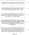
FIG. 4 is a schematic flowchart of a second data transmission method applied to the vehicle communication interface apparatus shown inFIG. 2 according to an embodiment of the present invention; -
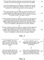
FIG. 5 is a schematic flowchart of a third data transmission method applied to the vehicle communication interface apparatus shown inFIG. 2 according to an embodiment of the present invention; and -
FIG. 6 is a schematic flowchart of an application example of a data transmission method applied to the vehicle communication interface apparatus shown inFIG. 2 according to an embodiment of the present invention. - To make objectives, the technical solutions, and advantages of the present invention clearer, the present invention is further described in detail with reference to accompanying drawings and embodiments. It is to be understood that the specific embodiments described herein are merely used for interpreting the present invention and are not intended to limit the present invention.
- It should be noted that the features in the embodiments of the present invention may be combined with each other if no conflict occurs, and all combinations fall within the protection scope of the present invention. In addition, although functional module division is performed in the schematic diagram of the apparatus and a logical sequence is shown in the flowchart, in some situations, the shown or described steps may be performed by module division different from that in the apparatus or in a sequence different from that in the flowchart. Moreover, words such as "first" and "second" adopted in the present invention do not constitute any limitation on the data and the execution sequence, and merely distinguish same items or similar items of which the functions and roles are basically the same.
- A traditional vehicle diagnosis system generally includes an upper computer and a lower computer. The upper computer is connected to the lower computer, and the lower computer is connected to a vehicle bus. The upper computer can send a diagnostic command to the lower computer, and the lower computer transmits the diagnostic command to the vehicle bus. The lower computer may further receive diagnostic data in the vehicle bus and transmit the diagnostic data to the upper computer. However, a lower computer of a current vehicle diagnosis system cannot respond to a diagnostic command and receive diagnostic data simultaneously.
- Based on this, the embodiments of the present invention provide a data transmission method in a vehicle communication interface apparatus and a vehicle communication interface apparatus, and the data transmission method in the vehicle communication interface apparatus and the vehicle communication interface apparatus can respond to a diagnostic command and receive diagnostic data simultaneously.
- The vehicle communication interface apparatus in the embodiments of the present invention may be connected to an upper computer and a to-be-checked vehicle, to perform the data transmission method in the embodiments of the present invention.
- The data transmission method in the embodiments of the present invention can be performed in any type of vehicle communication interface apparatus including a user interaction apparatus and a processor with a computing capability.
- Specifically, the embodiments of the present invention are further described below with reference to accompanying drawings.
-
FIG. 1 is a schematic structural diagram of a vehicle diagnosis system according to an embodiment of the present invention. As shown inFIG. 1 , thevehicle diagnosis system 100 includes anupper computer 10 and a vehiclecommunication interface apparatus 20. Theupper computer 10 is connected to the vehiclecommunication interface apparatus 20, and the vehiclecommunication interface apparatus 20 is configured to connect to avehicle 200. - The
upper computer 10 may be specifically any proper terminal device that is provided with a vehicle diagnosis function and on which an intelligent operating system is run, such as a mobile phone, a tablet computer, or an intelligent wearable device. A user (for example, a vehicle owner) may perform interaction with theupper computer 10 by using one or more user interaction devices of any proper type (for example, a touchscreen, a mouse, a keyboard, a remote control, a motion sensing camera, and an audio capture apparatus), to input an instruction or control theupper computer 10 to perform one or more operations. Client software of any type such as a vehicle diagnosis APP may be installed on theupper computer 10. The upper computer performs communication connection with the vehiclecommunication interface apparatus 20 through the client software, to send an instruction to the vehiclecommunication interface apparatus 20 or obtain data of the vehiclecommunication interface apparatus 20. - The vehicle
communication interface apparatus 20 may be a communication interface apparatus of a vehicle communication interface (VCI) type or another type. The vehiclecommunication interface apparatus 20 may be connected to an electronic control unit (ECU) in thevehicle 200 through an on-board diagnostics (OBD) system, to obtain diagnostic data in thevehicle 200 or transmit an instruction to thevehicle 200. Thevehicle 200 may be an automobile, a tram, a train, a truck, or the like, and performs data transmission with theupper computer 10 through the corresponding vehicle communication interface apparatus. Specifically, the vehiclecommunication interface apparatus 20 is connected to a bus (for example, a CAN bus) of the ECU in thevehicle 200. Optionally, the vehiclecommunication interface apparatus 20 may be provided with a Wi-Fi module, a USB module, a Bluetooth module and a mobile network module, and may establish a connection to theupper computer 10 according to a requirement. - Based on the foregoing
vehicle diagnosis system 100, in actual application, when a diagnosis needs to be performed on thevehicle 200, the user (the vehicle owner or a repair technician) may first connect to thevehicle 200 through the vehiclecommunication interface apparatus 20, to enable the vehiclecommunication interface apparatus 20 to read diagnostic data of thevehicle 200; and then establish a connection between theupper computer 10 and the vehiclecommunication interface apparatus 200, to enable the vehiclecommunication interface apparatus 20 to transmit the diagnostic data to theupper computer 10, or to receive a diagnostic command sent by the user through theupper computer 10, to perform a diagnosis on thevehicle 200. - It should be noted that the data transmission method in the vehicle communication interface apparatus according to the embodiments of the present invention may be further expanded to another proper implementation environment, and is not limited to the implementation environment shown in
FIG. 1 . AlthoughFIG. 1 shows only oneupper computer 10 and one vehiclecommunication interface apparatus 20, a person skilled in the art should understand that in an actual application process, the application environment may include moreupper computers 10 and more vehiclecommunication interface apparatuses 20. This is not specifically limited in the embodiments of the present invention - Referring to
FIG. 2 together, the vehiclecommunication interface apparatus 20 includes afirst controller 21 and asecond controller 22. - The
first controller 21 is configured to receive a diagnostic command sent by theupper computer 10, and store the diagnostic command into a first queue. Thefirst controller 21 is further configured to obtain diagnostic data from a second queue, and send the diagnostic data to theupper computer 10. - The
second controller 22 is configured to obtain the diagnostic command from the first queue, and send the diagnostic command to the ECU in thevehicle 200 connected to the vehiclecommunication interface apparatus 20. Thesecond controller 22 is further configured to receive the diagnostic data from the ECU in thevehicle 200, and store the diagnostic data into the second queue, to make thefirst controller 21 obtain the diagnostic data from the second queue and send the diagnostic data to theupper computer 10. - The
first controller 21 or thesecond controller 22 may further include a processor, an application-specific integrated circuit (ASIC) including a control processing function, a field programmable gate array (FPGA), a single chip microcomputer, and the like. Certainly, in some other embodiments, the vehiclecommunication interface apparatus 20 may further include other controllers, and two of the controllers may be selected to perform data transmission according to an actual requirement. This is not limited herein. - Optionally, as shown in
FIG. 2 , the vehiclecommunication interface apparatus 20 further includes amemory 23. Thememory 23 may include a volatile memory, for example, a random access memory (RAM) such as a static random-access memory (SRAM) or a double data rate synchronous dynamic random access memory (DDR SDRAM); the memory may also include a non-volatile memory, such as a flash memory, a hard disk drive (HDD) or a solid-state drive (SSD), an electrically erasable programmable read only memory (EEPROM); and the memory may further include a combination of the foregoing various memories. The memory may be an independent memory, or may be a memory or a module including a storage function in a chip (for example, a processor chip). The memory may store computer programs (for example, a control program for an image capture apparatus, a vehicle diagnosis program, or a functional module), a computer instruction, an operating system, data, a database, and the like. The memory may store the foregoing content in different areas - In this embodiment, the
memory 23 is connected to thefirst controller 21 and thesecond controller 22. The first queue and the second queue are disposed in thememory 23, to make thefirst controller 21 store the diagnostic command into the first queue or obtain the diagnostic data from the second queue, and to make thesecond controller 22 obtain the diagnostic command from the first queue or store the diagnostic data into the second queue. - It may be understood that, in some other embodiments, two or more memories may be disposed in the vehicle
communication interface apparatus 20. The first queue and the second queue are respectively disposed in different memories, and the two memories are respectively connected to thefirst controller 21 and thesecond controller 22, to implement data transmission. - Referring to
FIG. 3, FIG. 3 is a schematic flowchart of a data transmission method in a vehicle communication interface apparatus according to an embodiment of the present invention. As shown inFIG. 3 , the data transmission method is applied to the vehiclecommunication interface apparatus 20 in the foregoing embodiment, and the method includes:
S310. A first controller receives a diagnostic command sent by an upper computer, and stores the diagnostic command into a first queue. - In this embodiment, the "diagnostic command" may include a diagnostic identification command, a verification command, and the like. For example, diagnostic data of a corresponding vehicle module may be obtained through the diagnostic identification command, and whether the upper computer includes a diagnostic qualification is verified through the verification command. The upper computer may receive or transmit the diagnostic command. For example, the upper computer receives a diagnostic command from a user, or the upper computer transmits a diagnostic command sent by a terminal. In actual application, when a diagnosis needs to be performed on a vehicle, a communication connection to the
vehicle 200 may be first established through the vehiclecommunication interface apparatus 20, and then the user enters a diagnostic command related to thevehicle 200 and the vehiclecommunication interface apparatus 20 through theupper computer 10, and instructs theupper computer 10 to send the diagnostic command to the vehiclecommunication interface apparatus 20, to perform a vehicle diagnosis. - In this embodiment, a specific implementation of receiving the diagnostic command sent by the upper computer may be: determining whether the upper computer sends the diagnostic command, and if the upper computer sends the diagnostic command, receiving the diagnostic command sent by the upper computer.
- In this embodiment, when the
first controller 21 receives the diagnostic command sent by the upper computer, thefirst controller 21 stores the diagnostic command into the first queue in thememory 23. - S320. A second controller obtains the diagnostic command from the first queue, and sends the diagnostic command to an ECU in a vehicle connected to a vehicle communication interface apparatus.
- In this embodiment, after the
first controller 21 stores the diagnostic command into the first queue in thememory 23, thesecond controller 22 obtains the diagnostic command from the first queue and sends the diagnostic command to the ECU in thevehicle 200 connected to the vehiclecommunication interface apparatus 20, to make thevehicle 200 receive the diagnostic command sent by theupper computer 10. - S330. The
second controller 22 receives diagnostic data from the ECU, and stores the diagnostic data into a second queue, to make the first controller obtain the diagnostic data from the second queue and send the diagnostic data to the upper computer. - In this embodiment, the "diagnostic data" may be diagnostic data of some or all modules of the vehicle, and for example, may include current data information and historical data information of a motor module and a battery module. In actual application, the
second controller 22 is connected to a bus of the ECU in thevehicle 200, so that thesecond controller 22 may receive the diagnostic data of the ECU. Optionally, the ECU may upload the diagnostic data regularly according to preset duration, to make thesecond controller 22 regularly receive the diagnostic data uploaded by the ECU. - In this embodiment, when the
second controller 22 receives the diagnostic data, thesecond controller 22 stores the diagnostic data into the second queue of thememory 23. After thesecond controller 22 stores the diagnostic data into the second queue, thefirst controller 21 may obtain the diagnostic data from the second queue, to transmit the diagnostic data to theupper computer 10. - Optionally, priorities are preset for processing of the diagnostic data and the diagnostic command. For example, if the priority of the diagnostic command is set to be higher than that of the diagnostic data, the diagnostic command is preferentially processed. In the
first controller 21, when the priority of the diagnostic command is preset to be higher than that of the diagnostic data, as shown inFIG. 4 , the method further includes:
S341. When the first controller detects that the diagnostic data is stored in the second queue and receives the diagnostic command sent by the upper computer, the first controller obtains the diagnostic data from the second queue and sends the diagnostic data to the upper computer after the first controller stores the diagnostic command into the first queue. - When the
upper computer 10 sends the diagnostic command to thefirst controller 21 and the diagnostic data is stored in the second queue of thememory 23, thefirst controller 21 preferentially responds to the diagnostic command of theupper computer 10 and processes the diagnostic command, and then obtains the diagnostic data and sends the diagnostic data to theupper computer 10, so that the diagnostic command can be responded to quickly. - Optionally, in the
second controller 22, when the priority of the diagnostic data is preset to be higher than that of the diagnostic command, as shown inFIG. 4 , the method further includes:
S342. When the second data detects that the diagnostic command is stored in the first queue and receives the diagnostic data of the ECU, the second controller obtains the diagnostic command from the first queue and sends the diagnostic command to the ECU after the second controller stores the diagnostic data into the second queue. - When the ECU of the
vehicle 200 uploads the diagnostic data, and the diagnostic command is stored in the first queue of thememory 23, after thesecond controller 22 preferentially responds to the diagnostic data of thevehicle 200 and processes the diagnostic data, and then obtains the diagnostic command and sends the diagnostic command to the ECU of thevehicle 200, so that the diagnostic data can be responded to quickly. - It is necessary to be noted that an execution sequence of S310, S320, and S330 may be changed. For example, the execution sequence may be S330, S320, and S310. S341 and S342 may be performed simultaneously or may not be performed simultaneously, or only one of them is selected and performed
- In this embodiment, according to the data transmission method, the
first controller 21 receives the diagnostic command sent by theupper computer 10 and stores the diagnostic command into the first queue, and thesecond controller 22 obtains the diagnostic command from the first queue and sends the diagnostic command to thevehicle 200. Thesecond controller 22 further receives the diagnostic data from thevehicle 200 and stores the diagnostic data into the second queue, and thefirst controller 21 further obtains the diagnostic data from the second queue, thereby responding to the diagnostic command and receiving the diagnostic data simultaneously in the vehiclecommunication interface apparatus 20, to enable the vehiclecommunication interface apparatus 20 to perform data communication with theupper computer 10 and thevehicle 200 simultaneously, to avoid missing the diagnostic data or the diagnostic command. - Based on the foregoing embodiment, an embodiment of the present invention further provides another data transmission method in a vehicle communication interface apparatus shown in
FIG. 5 . Specifically, as shown inFIG. 5 , a difference between this embodiment and the foregoing embodiment lies in that:
In this embodiment, the vehiclecommunication interface apparatus 20 may determine the priorities of the diagnostic data and the diagnostic command, to determine a processing sequence for the diagnostic data and the diagnostic command. The data transmission method further includes:
S350. The first controller determines a processing sequence for the diagnostic data and the diagnostic command according to priorities of the diagnostic data and the diagnostic command when the first controller detects that the diagnostic data is stored in the second queue and receives the diagnostic command sent by the upper computer. - In this embodiment, "priorities of diagnostic data" refer to priorities of a plurality of pieces of diagnostic data stored in the second queue. The priority of the diagnostic data may be determined according to a data size of the diagnostic data and/or storage duration of the diagnostic data in the second queue. For example, a greater data volume of the diagnostic data is preset to have a higher priority. Assuming that the diagnostic data includes diagnostic data A and diagnostic data B, if the data volume of the diagnostic data A is greater than the data volume of the diagnostic data B, it is determined that the priority of the diagnostic data A is higher than that of the diagnostic data B, and the diagnostic data A is preferentially processed. For another example, longer storage duration of the diagnostic data in the second queue is preset to have a higher priority. It is assumed that the diagnostic data includes diagnostic data A and diagnostic data B, the storage duration of the diagnostic data A in the second queue is 1.1s, and the storage duration of the diagnostic data B in the second queue is Is, so that the storage duration of the diagnostic data A in the second queue is greater than the storage duration of the diagnostic data B in the second queue. Then it is determined that the priority of the diagnostic data A is higher than that of the diagnostic data B, and the diagnostic data A is preferentially processed. For still another example, a greater data volume of the diagnostic data is preset to have a higher priority, longer storage duration of the diagnostic data in the second queue is preset to have a higher priority, and occupied proportions of the data size and the storage duration are respectively 60% and 40%. If the data volume of the diagnostic data A is greater than the data volume of the diagnostic data B, and the storage duration of the diagnostic data A is greater than the storage duration of the diagnostic data B, it is determined that the priority of the diagnostic data A is higher than that of the diagnostic data B.
- In this embodiment, "priorities of diagnostic commands" refer to priorities of a plurality of diagnostic commands stored in the first queue. The priority of the diagnostic command may be determined according to urgency and/or importance of the diagnostic command. The "urgency" may be determined according to a sequence in which the diagnostic commands are stored into the first queue. For example, if a diagnostic command C is first stored into the first queue, and a diagnostic command D is then stored into the first queue, the urgency of the diagnostic command C is higher than the urgency of the diagnostic command D, and the priority of the diagnostic command C is higher than the priority of the diagnostic command D. The "importance" may be preset according to the type of the diagnostic command. For example, the importance of a security-class diagnostic command is set to be greater than the importance of a routine-class diagnostic command. The importance of the diagnostic command is preset, and a specific implementation may be: carrying an importance identifier in the diagnostic command. For example, if the diagnostic command C carries a low-level importance identifier, the diagnostic command D carries a high-level importance identifier, the priority of the diagnostic command C is higher than the priority of the diagnostic command D. When the priority of the diagnostic command is jointly determined according to the urgency and the importance of the diagnostic command, preset proportions may be set, and for example, occupied proportions of the urgency and the importance are respectively 60% and 40%, and the priority is determined according to the urgency, the importance, and the occupied proportions of the urgency and the importance.
- In S350, the determining, by the first controller, a processing sequence for the diagnostic data and the diagnostic command according to priorities of the diagnostic data and the diagnostic command may include:
- S351. The first controller compares the priority of the diagnostic command with the priority of the diagnostic data according to a preset rule.
- S352. The first controller first processes one of the diagnostic command and the diagnostic data of which the priority is higher.
- The "preset rule" includes: presetting a correspondence between the priority of the diagnostic command and the priority of the diagnostic data, and converting the priority of one of the diagnostic command and the diagnostic data into the priority of the other one of the diagnostic command and the diagnostic data according to the correspondence. For example, the preset correspondence between the priority of the diagnostic command and the priority of the diagnostic data is that by being multiplied by 0.6, the priority of the diagnostic data is converted into the priority of the diagnostic command. Assuming that the priorities of the diagnostic data A and the diagnostic data B in the diagnostic data are respectively 60% and 40% and the priorities of the diagnostic command C and the diagnostic command D in the diagnostic command are respectively 70% and 30%, the priorities of the diagnostic command C and the diagnostic command D in the diagnostic data are 42% and 18%, and the priorities in descending order are respectively the diagnostic data A, the diagnostic command C, the diagnostic data B, and the diagnostic command D. Certainly, in some other embodiments, the preset correspondence between the priority of the diagnostic command and the priority of the diagnostic data may be another one, and may be set according to an actual use requirement.
- In this embodiment, when determining the priority of the diagnostic command and the priority of the diagnostic data, the first controller preferentially processes one of the diagnostic command and the diagnostic data of which the priority is higher according to the priority of the diagnostic command and the priority of the diagnostic data, to enable the diagnostic command or the diagnostic data to be responded to quickly.
- Optionally, in some other embodiments, the data transmission method further includes:
S360. The second controller determines a processing sequence for the diagnostic data and the diagnostic command according to priorities of the diagnostic data and the diagnostic command when the second controller detects that the diagnostic command is stored in the first queue and receives the diagnostic data sent by the ECU. - In S360, the determining, by the second controller, a processing sequence for the diagnostic data and the diagnostic command according to priorities of the diagnostic data and the diagnostic command may include:
- S361. The second controller compares the priority of the diagnostic command with the priority of the diagnostic data according to a preset rule.
- S362. The second controller first processes one of the diagnostic command and the diagnostic data of which the priority is higher.
- It is necessary to be noted that the preset rule in the first controller and the preset rule in the second controller may be the same or may be different, and may be determined according to an actual use scenario.
- In this embodiment, the vehicle
communication interface apparatus 20 may determine the priorities of the diagnostic data and the diagnostic command, to determine the processing sequence for the diagnostic data and the diagnostic command. In this way, the vehiclecommunication interface apparatus 20 may respond to the diagnostic command and receive the diagnostic data according to a requirement, so that the vehiclecommunication interface apparatus 20 may perform data communication with theupper computer 10 and thevehicle 200, to avoid missing the diagnostic data or the diagnostic command. - Referring to
FIG. 6, FIG. 6 is a schematic flowchart of an application example of a data transmission method in a vehicle communication interface apparatus according to an embodiment of the present invention. As shown inFIG. 6 , - S411. A first controller receives a diagnostic command sent by an upper computer, and stores the diagnostic command into a first queue;
- S412. A second controller receives diagnostic data from an ECU, and stores the diagnostic data into a second queue;
- S421. The first controller obtains the diagnostic data from the second queue, and sends the diagnostic data to the upper computer.
- S422. The second controller obtains the diagnostic command from the first queue, and sends the diagnostic command to the ECU in a vehicle.
- S411 and S412 may be performed simultaneously or may not be performed simultaneously, and S421 and S422 may be performed simultaneously or may not be performed simultaneously.
- In this embodiment, by presetting the priority of the diagnostic command to be higher than the priority of the diagnostic data in the first controller and the priority of the diagnostic data to be higher than the priority of the diagnostic command in the second controller, the vehicle
communication interface apparatus 20 may perform processing according to the preset priorities of the diagnostic data and the diagnostic command, so that the vehiclecommunication interface apparatus 20 may perform data communication with theupper computer 10 and thevehicle 200 simultaneously, to avoid missing the diagnostic data or the diagnostic command. - The apparatus embodiments described above are merely exemplary, where the units described as separated parts may be or may not be physically separated, and parts displayed as units may be or may not be physical units. That is, the parts may be located in the same place, or may be distributed to a plurality of network units. Some or all of the modules may be selected according to an actual requirement to implement the objective of the solution of this embodiment.
- Based on the descriptions of the foregoing implementations, a person skilled in the art should clearly understand that the implementations may be implemented by using software and a hardware platform, or may be implemented by using hardware. A person skilled in the art may understand that all or some of the processes in the method of the foregoing embodiment may be completed by using computer programs in a computer program product to instruct corresponding hardware, and the computer programs may be stored in a non-transient computer-readable storage medium. The computer programs include program instructions, and the program instructions, when being performed by a related device, cause the related device to perform the procedure of the embodiments of the foregoing methods. The storage medium may be a magnetic disk, an optical disc, a read-only memory (ROM) or a random access memory (RAM), or the like.
- The product may perform the data transmission method provided in the embodiments of the present invention, and includes corresponding functional modules and beneficial effects for performing the data transmission method. For technical details not described in detail in the embodiments, reference may be made to the data transmission method provided in the embodiments of the present invention.
- It should be finally noted that, the foregoing embodiments are merely used for describing the technical solution of the present invention and are not intended to limit the present invention. Based on the idea of the present invention, technical features in the foregoing embodiment or different embodiments may be combined, the steps may be implemented in any sequence, various other variations on different aspects of the present invention also exist, and for brevity, they are not provided in detail. Although detailed descriptions of the present invention are performed with reference to the foregoing embodiments, a person skilled in the art should understand that, modifications may be performed on the technical solutions recorded in the foregoing embodiments, or equivalent replacement may be performed on some technical features, and these modifications or replacements may not make the essence of the corresponding technical solutions depart from the scope of the technical solutions of the embodiments of the present invention.
Claims (10)
- A data transmission method in a vehicle communication interface apparatus, wherein the vehicle communication interface apparatus comprises a first controller and a second controller, and the method comprises:receiving, by the first controller, a diagnostic command sent by an upper computer, and storing the diagnostic command into a first queue;obtaining, by the second controller, the diagnostic command from the first queue, and sending the diagnostic command to an electronic control unit (ECU) in a vehicle connected to the vehicle communication interface apparatus; andreceiving, by the second controller, diagnostic data from the ECU, and storing the diagnostic data into a second queue, to make the first controller obtain the diagnostic data from the second queue and send the diagnostic data to the upper computer.
- The method according to claim 1, wherein the method further comprises:
determining, by the first controller, a processing sequence for the diagnostic data and the diagnostic command according to priorities of the diagnostic data and the diagnostic command when the first controller detects that the diagnostic data is stored in the second queue and receives the diagnostic command sent by the upper computer. - The method according to claim 2, wherein
the priority of the diagnostic data is determined according to a data size of the diagnostic data and/or storage duration of the diagnostic data in the second queue; and
the priority of the diagnostic command is determined according to urgency and/or importance of the diagnostic command. - The method according to claim 3, wherein the determining, by the first controller, a processing sequence for the diagnostic data and the diagnostic command according to priorities of the diagnostic data and the diagnostic command comprises:comparing, by the first controller, the priority of the diagnostic command with the priority of the diagnostic data according to a preset rule; andfirst processing, by the first controller, one of the diagnostic command and the diagnostic data of which the priority is higher, whereinthe preset rule comprises:
presetting a correspondence between the priority of the diagnostic command and the priority of the diagnostic data, and converting the priority of one of the diagnostic command and the diagnostic data into the priority of the other one of the diagnostic command and the diagnostic data according to the correspondence. - The method according to claim 1, wherein the method further comprises:
when the first controller detects that the diagnostic data is stored in the second queue and receives the diagnostic command sent by the upper computer, obtaining, by the first controller, the diagnostic data from the second queue and sending the diagnostic data to the upper computer after the first controller stores the diagnostic command into the first queue. - A vehicle communication interface apparatus, wherein the vehicle communication interface apparatus comprises a first controller and a second controller,
the first controller is configured to receive a diagnostic command sent by an upper computer, and store the diagnostic command into a first queue;
the second controller is configured to obtain the diagnostic command from the first queue, and send the diagnostic command to an ECU in a vehicle connected to the vehicle communication interface apparatus; and
the second controller is further configured to receive diagnostic data from the ECU, and store the diagnostic data into a second queue, to make the first controller obtain the diagnostic data from the second queue and send the diagnostic data to the upper computer. - The vehicle communication interface apparatus according to claim 6, wherein
the first controller is further configured to determine a processing sequence for the diagnostic data and the diagnostic command according to priorities of the diagnostic data and the diagnostic command when the first controller detects that the diagnostic data is stored in the second queue and receives the diagnostic command sent by the upper computer. - The vehicle communication interface apparatus according to claim 7, wherein
the priority of the diagnostic data is determined according to a data size of the diagnostic data and/or storage duration of the diagnostic data in the second queue; and
the priority of the diagnostic command is determined according to urgency and/or importance of the diagnostic command. - The vehicle communication interface apparatus according to claim 8, wherein the first controller is specifically configured to:compare the priority of the diagnostic command with the priority of the diagnostic data according to a preset rule; andfirst process one of the diagnostic command and the diagnostic data of which the priority is higher, whereinthe preset rule comprises:
presetting a correspondence between the priority of the diagnostic command and the priority of the diagnostic data, and converting the priority of one of the diagnostic command and the diagnostic data into the priority of the other one of the diagnostic command and the diagnostic data according to the correspondence. - The vehicle communication interface apparatus according to claim 1, wherein
the first controller is further configured to, when the first controller detects that the diagnostic data is stored in the second queue and receives the diagnostic command sent by the upper computer, obtain the diagnostic data from the second queue and send the diagnostic data to the upper computer after the first controller stores the diagnostic command into the first queue.
Applications Claiming Priority (2)
| Application Number | Priority Date | Filing Date | Title |
|---|---|---|---|
| CN201811639171.3A CN109639597B (en) | 2018-12-29 | 2018-12-29 | Data transmission method in vehicle communication interface device and vehicle communication interface device |
| PCT/CN2019/129877 WO2020135865A1 (en) | 2018-12-29 | 2019-12-30 | Data transmission method in vehicle communication interface apparatus, and vehicle communication interface apparatus |
Publications (3)
| Publication Number | Publication Date |
|---|---|
| EP3805886A1 true EP3805886A1 (en) | 2021-04-14 |
| EP3805886A4 EP3805886A4 (en) | 2021-09-29 |
| EP3805886B1 EP3805886B1 (en) | 2023-11-22 |
Family
ID=66054695
Family Applications (1)
| Application Number | Title | Priority Date | Filing Date |
|---|---|---|---|
| EP19904261.5A Active EP3805886B1 (en) | 2018-12-29 | 2019-12-30 | Data transmission method in vehicle communication interface apparatus, and vehicle communication interface apparatus |
Country Status (5)
| Country | Link |
|---|---|
| US (1) | US20210134086A1 (en) |
| EP (1) | EP3805886B1 (en) |
| CN (2) | CN113472619A (en) |
| DE (1) | DE212019000335U1 (en) |
| WO (1) | WO2020135865A1 (en) |
Families Citing this family (11)
| Publication number | Priority date | Publication date | Assignee | Title |
|---|---|---|---|---|
| CN113472619A (en) * | 2018-12-29 | 2021-10-01 | 深圳市道通科技股份有限公司 | Data transmission method in vehicle communication interface device and vehicle communication interface device |
| CN110850841A (en) * | 2019-10-30 | 2020-02-28 | 深圳市元征科技股份有限公司 | Fault diagnosis method and related device |
| CN110912992B (en) * | 2019-11-22 | 2022-09-16 | 深圳市元征科技股份有限公司 | Diagnostic data transmission method, device, equipment and system |
| CN111290845A (en) * | 2020-01-15 | 2020-06-16 | 深圳市元征科技股份有限公司 | Data transmission method, device, equipment and storage medium |
| CN113507402A (en) * | 2021-04-07 | 2021-10-15 | 惠州市德赛西威汽车电子股份有限公司 | TBOX diagnosis method for passive CAN |
| CN114980013A (en) * | 2021-07-23 | 2022-08-30 | 长城汽车股份有限公司 | Data channel management method and device based on Bluetooth module, electronic equipment and vehicle |
| CN114866585B (en) * | 2022-04-24 | 2024-09-10 | 深圳市元征科技股份有限公司 | Remote upgrading method, device, system and equipment end connector |
| CN114802055A (en) * | 2022-05-17 | 2022-07-29 | 联陆智能交通科技(上海)有限公司 | Tbox remote control-based data control separated vehicle control method and system |
| CN115515128A (en) * | 2022-08-12 | 2022-12-23 | 长春捷翼汽车零部件有限公司 | Wireless transmission method, computer device and storage medium |
| CN115494819B (en) * | 2022-08-15 | 2025-09-09 | 北京车和家信息技术有限公司 | Vehicle diagnosis method, diagnosis device, diagnosis apparatus, medium, and vehicle |
| CN119149135A (en) * | 2024-11-12 | 2024-12-17 | 惠州市乐亿通科技股份有限公司 | Configuration method of upper computer and electronic device |
Family Cites Families (10)
| Publication number | Priority date | Publication date | Assignee | Title |
|---|---|---|---|---|
| JP2004126707A (en) * | 2002-09-30 | 2004-04-22 | Fujitsu Ltd | Interface conversion device and interface conversion method |
| US8866911B1 (en) * | 2013-12-09 | 2014-10-21 | American Megatrends, Inc. | Digital signage device capable of entering diagnostic display mode |
| US20160330284A1 (en) * | 2015-05-07 | 2016-11-10 | Novatel Wireless, Inc. | Systems and methods for server based processing of on board diagnostics (obd) data |
| CN107562669B (en) * | 2016-06-30 | 2020-04-07 | 北京忆芯科技有限公司 | NVMe protocol command processing method, device and system |
| CN108243212B (en) * | 2016-12-24 | 2021-07-20 | 宝沃汽车(中国)有限公司 | Method and device for vehicle diagnosis |
| CN106959682A (en) * | 2017-03-06 | 2017-07-18 | 深圳市元征软件开发有限公司 | A kind of vehicle diagnosis method, diagnosis joint, and diagnostic system |
| CN106993056A (en) * | 2017-05-12 | 2017-07-28 | 深圳市元征科技股份有限公司 | Car data stream acquisition methods, system and computer-readable recording medium |
| CN108445868B (en) * | 2018-03-26 | 2020-12-29 | 安徽省爱夫卡电子科技有限公司 | Intelligent automobile fault diagnosis system and method based on modern signal processing technology |
| CN108983759A (en) * | 2018-09-25 | 2018-12-11 | 深圳市道通科技股份有限公司 | A kind of vehicle diagnostic device and Vehicular diagnostic method |
| CN113472619A (en) * | 2018-12-29 | 2021-10-01 | 深圳市道通科技股份有限公司 | Data transmission method in vehicle communication interface device and vehicle communication interface device |
-
2018
- 2018-12-29 CN CN202110626090.5A patent/CN113472619A/en active Pending
- 2018-12-29 CN CN201811639171.3A patent/CN109639597B/en active Active
-
2019
- 2019-12-30 WO PCT/CN2019/129877 patent/WO2020135865A1/en not_active Ceased
- 2019-12-30 DE DE212019000335.4U patent/DE212019000335U1/en active Active
- 2019-12-30 EP EP19904261.5A patent/EP3805886B1/en active Active
-
2021
- 2021-01-11 US US17/146,015 patent/US20210134086A1/en not_active Abandoned
Also Published As
| Publication number | Publication date |
|---|---|
| EP3805886B1 (en) | 2023-11-22 |
| CN109639597A (en) | 2019-04-16 |
| DE212019000335U1 (en) | 2021-03-31 |
| EP3805886A4 (en) | 2021-09-29 |
| CN109639597B (en) | 2021-06-25 |
| WO2020135865A1 (en) | 2020-07-02 |
| CN113472619A (en) | 2021-10-01 |
| US20210134086A1 (en) | 2021-05-06 |
Similar Documents
| Publication | Publication Date | Title |
|---|---|---|
| US20210134086A1 (en) | Data transmission method in vehicle communication interface apparatus and vehicle communication interface apparatus | |
| CN108933993B (en) | Short message cache queue selection method and device, computer equipment and storage medium | |
| DE102015220844B4 (en) | Method and head unit for performing Bluetooth pairing | |
| US9355507B1 (en) | System and method for collecting data of vehicle | |
| CN110851271B (en) | Resource sharing method and device and storage medium | |
| CN108521459A (en) | Vehicle diagnosis method, related equipment and system | |
| CN111464419B (en) | Data transmission control method based on bus network communication | |
| US20220326931A1 (en) | System and method for managing update of electronic control unit of vehicle | |
| CN111627435A (en) | Speech recognition method and system and control method and system based on speech command | |
| CN112363767A (en) | Vehicle-mounted camera calling method and device | |
| US10759306B2 (en) | Seat adjustment device | |
| US20140343753A1 (en) | System and method for vehicle interface extension and control | |
| CN106034111B (en) | Method for authenticating CAN packet using hybrid MAC and apparatus for implementing the same | |
| RU2012138384A (en) | VEHICLE INDIVIDUAL FOR DRIVER CONFIGURATION | |
| KR102135357B1 (en) | Cloud service interworking apparatus and method thereof | |
| CN111580769A (en) | Display control system, method, device, storage medium and processor | |
| KR20190115361A (en) | Electronic device for managing application associated with a key of external electronic device and the method for the same | |
| WO2025060630A1 (en) | Method and apparatus for controlling login of in-vehicle infotainment application software, and electronic device and storage medium | |
| CN104836785B (en) | Terminal authentication system and method for vehicle network connection | |
| CN114554444B (en) | Virtual SIM for Vehicles | |
| US10691399B2 (en) | Method of displaying mobile device content and apparatus thereof | |
| US12335663B2 (en) | Method and system for collecting and reporting evidence following a vehicle incident | |
| CN115493079B (en) | Hydrogen filling system and hydrogen filling method | |
| US10448248B2 (en) | Methods and devices for controlling authorization to communication information | |
| US10026450B2 (en) | Content processing and distribution system and method |
Legal Events
| Date | Code | Title | Description |
|---|---|---|---|
| STAA | Information on the status of an ep patent application or granted ep patent |
Free format text: STATUS: THE INTERNATIONAL PUBLICATION HAS BEEN MADE |
|
| PUAI | Public reference made under article 153(3) epc to a published international application that has entered the european phase |
Free format text: ORIGINAL CODE: 0009012 |
|
| STAA | Information on the status of an ep patent application or granted ep patent |
Free format text: STATUS: REQUEST FOR EXAMINATION WAS MADE |
|
| 17P | Request for examination filed |
Effective date: 20210105 |
|
| AK | Designated contracting states |
Kind code of ref document: A1 Designated state(s): AL AT BE BG CH CY CZ DE DK EE ES FI FR GB GR HR HU IE IS IT LI LT LU LV MC MK MT NL NO PL PT RO RS SE SI SK SM TR |
|
| AX | Request for extension of the european patent |
Extension state: BA ME |
|
| A4 | Supplementary search report drawn up and despatched |
Effective date: 20210901 |
|
| RIC1 | Information provided on ipc code assigned before grant |
Ipc: H04L 12/865 20130101ALI20210826BHEP Ipc: G05B 23/02 20060101AFI20210826BHEP |
|
| DAV | Request for validation of the european patent (deleted) | ||
| DAX | Request for extension of the european patent (deleted) | ||
| STAA | Information on the status of an ep patent application or granted ep patent |
Free format text: STATUS: EXAMINATION IS IN PROGRESS |
|
| 17Q | First examination report despatched |
Effective date: 20221201 |
|
| RIC1 | Information provided on ipc code assigned before grant |
Ipc: H04L 12/40 20060101ALI20230731BHEP Ipc: G05B 23/02 20060101AFI20230731BHEP |
|
| GRAP | Despatch of communication of intention to grant a patent |
Free format text: ORIGINAL CODE: EPIDOSNIGR1 |
|
| STAA | Information on the status of an ep patent application or granted ep patent |
Free format text: STATUS: GRANT OF PATENT IS INTENDED |
|
| GRAS | Grant fee paid |
Free format text: ORIGINAL CODE: EPIDOSNIGR3 |
|
| INTG | Intention to grant announced |
Effective date: 20230919 |
|
| GRAA | (expected) grant |
Free format text: ORIGINAL CODE: 0009210 |
|
| STAA | Information on the status of an ep patent application or granted ep patent |
Free format text: STATUS: THE PATENT HAS BEEN GRANTED |
|
| AK | Designated contracting states |
Kind code of ref document: B1 Designated state(s): AL AT BE BG CH CY CZ DE DK EE ES FI FR GB GR HR HU IE IS IT LI LT LU LV MC MK MT NL NO PL PT RO RS SE SI SK SM TR |
|
| REG | Reference to a national code |
Ref country code: GB Ref legal event code: FG4D |
|
| REG | Reference to a national code |
Ref country code: CH Ref legal event code: EP Ref country code: DE Ref legal event code: R096 Ref document number: 602019042104 Country of ref document: DE |
|
| REG | Reference to a national code |
Ref country code: IE Ref legal event code: FG4D |
|
| REG | Reference to a national code |
Ref country code: LT Ref legal event code: MG9D |
|
| REG | Reference to a national code |
Ref country code: NL Ref legal event code: MP Effective date: 20231122 |
|
| PG25 | Lapsed in a contracting state [announced via postgrant information from national office to epo] |
Ref country code: GR Free format text: LAPSE BECAUSE OF FAILURE TO SUBMIT A TRANSLATION OF THE DESCRIPTION OR TO PAY THE FEE WITHIN THE PRESCRIBED TIME-LIMIT Effective date: 20240223 |
|
| PG25 | Lapsed in a contracting state [announced via postgrant information from national office to epo] |
Ref country code: IS Free format text: LAPSE BECAUSE OF FAILURE TO SUBMIT A TRANSLATION OF THE DESCRIPTION OR TO PAY THE FEE WITHIN THE PRESCRIBED TIME-LIMIT Effective date: 20240322 |
|
| PG25 | Lapsed in a contracting state [announced via postgrant information from national office to epo] |
Ref country code: LT Free format text: LAPSE BECAUSE OF FAILURE TO SUBMIT A TRANSLATION OF THE DESCRIPTION OR TO PAY THE FEE WITHIN THE PRESCRIBED TIME-LIMIT Effective date: 20231122 |
|
| REG | Reference to a national code |
Ref country code: AT Ref legal event code: MK05 Ref document number: 1634401 Country of ref document: AT Kind code of ref document: T Effective date: 20231122 |
|
| PG25 | Lapsed in a contracting state [announced via postgrant information from national office to epo] |
Ref country code: NL Free format text: LAPSE BECAUSE OF FAILURE TO SUBMIT A TRANSLATION OF THE DESCRIPTION OR TO PAY THE FEE WITHIN THE PRESCRIBED TIME-LIMIT Effective date: 20231122 |
|
| PG25 | Lapsed in a contracting state [announced via postgrant information from national office to epo] |
Ref country code: AT Free format text: LAPSE BECAUSE OF FAILURE TO SUBMIT A TRANSLATION OF THE DESCRIPTION OR TO PAY THE FEE WITHIN THE PRESCRIBED TIME-LIMIT Effective date: 20231122 |
|
| PG25 | Lapsed in a contracting state [announced via postgrant information from national office to epo] |
Ref country code: ES Free format text: LAPSE BECAUSE OF FAILURE TO SUBMIT A TRANSLATION OF THE DESCRIPTION OR TO PAY THE FEE WITHIN THE PRESCRIBED TIME-LIMIT Effective date: 20231122 |
|
| PG25 | Lapsed in a contracting state [announced via postgrant information from national office to epo] |
Ref country code: NL Free format text: LAPSE BECAUSE OF FAILURE TO SUBMIT A TRANSLATION OF THE DESCRIPTION OR TO PAY THE FEE WITHIN THE PRESCRIBED TIME-LIMIT Effective date: 20231122 Ref country code: LT Free format text: LAPSE BECAUSE OF FAILURE TO SUBMIT A TRANSLATION OF THE DESCRIPTION OR TO PAY THE FEE WITHIN THE PRESCRIBED TIME-LIMIT Effective date: 20231122 Ref country code: IS Free format text: LAPSE BECAUSE OF FAILURE TO SUBMIT A TRANSLATION OF THE DESCRIPTION OR TO PAY THE FEE WITHIN THE PRESCRIBED TIME-LIMIT Effective date: 20240322 Ref country code: GR Free format text: LAPSE BECAUSE OF FAILURE TO SUBMIT A TRANSLATION OF THE DESCRIPTION OR TO PAY THE FEE WITHIN THE PRESCRIBED TIME-LIMIT Effective date: 20240223 Ref country code: ES Free format text: LAPSE BECAUSE OF FAILURE TO SUBMIT A TRANSLATION OF THE DESCRIPTION OR TO PAY THE FEE WITHIN THE PRESCRIBED TIME-LIMIT Effective date: 20231122 Ref country code: BG Free format text: LAPSE BECAUSE OF FAILURE TO SUBMIT A TRANSLATION OF THE DESCRIPTION OR TO PAY THE FEE WITHIN THE PRESCRIBED TIME-LIMIT Effective date: 20240222 Ref country code: AT Free format text: LAPSE BECAUSE OF FAILURE TO SUBMIT A TRANSLATION OF THE DESCRIPTION OR TO PAY THE FEE WITHIN THE PRESCRIBED TIME-LIMIT Effective date: 20231122 Ref country code: PT Free format text: LAPSE BECAUSE OF FAILURE TO SUBMIT A TRANSLATION OF THE DESCRIPTION OR TO PAY THE FEE WITHIN THE PRESCRIBED TIME-LIMIT Effective date: 20240322 |
|
| PG25 | Lapsed in a contracting state [announced via postgrant information from national office to epo] |
Ref country code: SE Free format text: LAPSE BECAUSE OF FAILURE TO SUBMIT A TRANSLATION OF THE DESCRIPTION OR TO PAY THE FEE WITHIN THE PRESCRIBED TIME-LIMIT Effective date: 20231122 Ref country code: RS Free format text: LAPSE BECAUSE OF FAILURE TO SUBMIT A TRANSLATION OF THE DESCRIPTION OR TO PAY THE FEE WITHIN THE PRESCRIBED TIME-LIMIT Effective date: 20231122 Ref country code: PL Free format text: LAPSE BECAUSE OF FAILURE TO SUBMIT A TRANSLATION OF THE DESCRIPTION OR TO PAY THE FEE WITHIN THE PRESCRIBED TIME-LIMIT Effective date: 20231122 Ref country code: NO Free format text: LAPSE BECAUSE OF FAILURE TO SUBMIT A TRANSLATION OF THE DESCRIPTION OR TO PAY THE FEE WITHIN THE PRESCRIBED TIME-LIMIT Effective date: 20240222 Ref country code: LV Free format text: LAPSE BECAUSE OF FAILURE TO SUBMIT A TRANSLATION OF THE DESCRIPTION OR TO PAY THE FEE WITHIN THE PRESCRIBED TIME-LIMIT Effective date: 20231122 Ref country code: HR Free format text: LAPSE BECAUSE OF FAILURE TO SUBMIT A TRANSLATION OF THE DESCRIPTION OR TO PAY THE FEE WITHIN THE PRESCRIBED TIME-LIMIT Effective date: 20231122 |
|
| PG25 | Lapsed in a contracting state [announced via postgrant information from national office to epo] |
Ref country code: DK Free format text: LAPSE BECAUSE OF FAILURE TO SUBMIT A TRANSLATION OF THE DESCRIPTION OR TO PAY THE FEE WITHIN THE PRESCRIBED TIME-LIMIT Effective date: 20231122 |
|
| PG25 | Lapsed in a contracting state [announced via postgrant information from national office to epo] |
Ref country code: CZ Free format text: LAPSE BECAUSE OF FAILURE TO SUBMIT A TRANSLATION OF THE DESCRIPTION OR TO PAY THE FEE WITHIN THE PRESCRIBED TIME-LIMIT Effective date: 20231122 |
|
| PG25 | Lapsed in a contracting state [announced via postgrant information from national office to epo] |
Ref country code: SK Free format text: LAPSE BECAUSE OF FAILURE TO SUBMIT A TRANSLATION OF THE DESCRIPTION OR TO PAY THE FEE WITHIN THE PRESCRIBED TIME-LIMIT Effective date: 20231122 |
|
| PG25 | Lapsed in a contracting state [announced via postgrant information from national office to epo] |
Ref country code: SM Free format text: LAPSE BECAUSE OF FAILURE TO SUBMIT A TRANSLATION OF THE DESCRIPTION OR TO PAY THE FEE WITHIN THE PRESCRIBED TIME-LIMIT Effective date: 20231122 Ref country code: SK Free format text: LAPSE BECAUSE OF FAILURE TO SUBMIT A TRANSLATION OF THE DESCRIPTION OR TO PAY THE FEE WITHIN THE PRESCRIBED TIME-LIMIT Effective date: 20231122 Ref country code: RO Free format text: LAPSE BECAUSE OF FAILURE TO SUBMIT A TRANSLATION OF THE DESCRIPTION OR TO PAY THE FEE WITHIN THE PRESCRIBED TIME-LIMIT Effective date: 20231122 Ref country code: IT Free format text: LAPSE BECAUSE OF FAILURE TO SUBMIT A TRANSLATION OF THE DESCRIPTION OR TO PAY THE FEE WITHIN THE PRESCRIBED TIME-LIMIT Effective date: 20231122 Ref country code: EE Free format text: LAPSE BECAUSE OF FAILURE TO SUBMIT A TRANSLATION OF THE DESCRIPTION OR TO PAY THE FEE WITHIN THE PRESCRIBED TIME-LIMIT Effective date: 20231122 Ref country code: DK Free format text: LAPSE BECAUSE OF FAILURE TO SUBMIT A TRANSLATION OF THE DESCRIPTION OR TO PAY THE FEE WITHIN THE PRESCRIBED TIME-LIMIT Effective date: 20231122 Ref country code: CZ Free format text: LAPSE BECAUSE OF FAILURE TO SUBMIT A TRANSLATION OF THE DESCRIPTION OR TO PAY THE FEE WITHIN THE PRESCRIBED TIME-LIMIT Effective date: 20231122 |
|
| REG | Reference to a national code |
Ref country code: CH Ref legal event code: PL |
|
| PG25 | Lapsed in a contracting state [announced via postgrant information from national office to epo] |
Ref country code: LU Free format text: LAPSE BECAUSE OF NON-PAYMENT OF DUE FEES Effective date: 20231230 |
|
| REG | Reference to a national code |
Ref country code: DE Ref legal event code: R097 Ref document number: 602019042104 Country of ref document: DE |
|
| PG25 | Lapsed in a contracting state [announced via postgrant information from national office to epo] |
Ref country code: MC Free format text: LAPSE BECAUSE OF FAILURE TO SUBMIT A TRANSLATION OF THE DESCRIPTION OR TO PAY THE FEE WITHIN THE PRESCRIBED TIME-LIMIT Effective date: 20231122 |
|
| REG | Reference to a national code |
Ref country code: BE Ref legal event code: MM Effective date: 20231231 |
|
| PG25 | Lapsed in a contracting state [announced via postgrant information from national office to epo] |
Ref country code: MC Free format text: LAPSE BECAUSE OF FAILURE TO SUBMIT A TRANSLATION OF THE DESCRIPTION OR TO PAY THE FEE WITHIN THE PRESCRIBED TIME-LIMIT Effective date: 20231122 Ref country code: LU Free format text: LAPSE BECAUSE OF NON-PAYMENT OF DUE FEES Effective date: 20231230 |
|
| PLBE | No opposition filed within time limit |
Free format text: ORIGINAL CODE: 0009261 |
|
| STAA | Information on the status of an ep patent application or granted ep patent |
Free format text: STATUS: NO OPPOSITION FILED WITHIN TIME LIMIT |
|
| REG | Reference to a national code |
Ref country code: IE Ref legal event code: MM4A |
|
| PG25 | Lapsed in a contracting state [announced via postgrant information from national office to epo] |
Ref country code: IE Free format text: LAPSE BECAUSE OF NON-PAYMENT OF DUE FEES Effective date: 20231230 |
|
| PG25 | Lapsed in a contracting state [announced via postgrant information from national office to epo] |
Ref country code: BE Free format text: LAPSE BECAUSE OF NON-PAYMENT OF DUE FEES Effective date: 20231231 |
|
| PG25 | Lapsed in a contracting state [announced via postgrant information from national office to epo] |
Ref country code: CH Free format text: LAPSE BECAUSE OF NON-PAYMENT OF DUE FEES Effective date: 20231231 |
|
| PG25 | Lapsed in a contracting state [announced via postgrant information from national office to epo] |
Ref country code: SI Free format text: LAPSE BECAUSE OF FAILURE TO SUBMIT A TRANSLATION OF THE DESCRIPTION OR TO PAY THE FEE WITHIN THE PRESCRIBED TIME-LIMIT Effective date: 20231122 |
|
| 26N | No opposition filed |
Effective date: 20240823 |
|
| PG25 | Lapsed in a contracting state [announced via postgrant information from national office to epo] |
Ref country code: SI Free format text: LAPSE BECAUSE OF FAILURE TO SUBMIT A TRANSLATION OF THE DESCRIPTION OR TO PAY THE FEE WITHIN THE PRESCRIBED TIME-LIMIT Effective date: 20231122 Ref country code: IE Free format text: LAPSE BECAUSE OF NON-PAYMENT OF DUE FEES Effective date: 20231230 Ref country code: CH Free format text: LAPSE BECAUSE OF NON-PAYMENT OF DUE FEES Effective date: 20231231 Ref country code: BE Free format text: LAPSE BECAUSE OF NON-PAYMENT OF DUE FEES Effective date: 20231231 |
|
| PG25 | Lapsed in a contracting state [announced via postgrant information from national office to epo] |
Ref country code: FI Free format text: LAPSE BECAUSE OF FAILURE TO SUBMIT A TRANSLATION OF THE DESCRIPTION OR TO PAY THE FEE WITHIN THE PRESCRIBED TIME-LIMIT Effective date: 20231122 |
|
| PG25 | Lapsed in a contracting state [announced via postgrant information from national office to epo] |
Ref country code: CY Free format text: LAPSE BECAUSE OF FAILURE TO SUBMIT A TRANSLATION OF THE DESCRIPTION OR TO PAY THE FEE WITHIN THE PRESCRIBED TIME-LIMIT; INVALID AB INITIO Effective date: 20191230 |
|
| PG25 | Lapsed in a contracting state [announced via postgrant information from national office to epo] |
Ref country code: HU Free format text: LAPSE BECAUSE OF FAILURE TO SUBMIT A TRANSLATION OF THE DESCRIPTION OR TO PAY THE FEE WITHIN THE PRESCRIBED TIME-LIMIT; INVALID AB INITIO Effective date: 20191230 |
|
| PG25 | Lapsed in a contracting state [announced via postgrant information from national office to epo] |
Ref country code: TR Free format text: LAPSE BECAUSE OF FAILURE TO SUBMIT A TRANSLATION OF THE DESCRIPTION OR TO PAY THE FEE WITHIN THE PRESCRIBED TIME-LIMIT Effective date: 20231122 |
|
| PGFP | Annual fee paid to national office [announced via postgrant information from national office to epo] |
Ref country code: GB Payment date: 20251229 Year of fee payment: 7 |
|
| PGFP | Annual fee paid to national office [announced via postgrant information from national office to epo] |
Ref country code: FR Payment date: 20251222 Year of fee payment: 7 |
|
| PGFP | Annual fee paid to national office [announced via postgrant information from national office to epo] |
Ref country code: DE Payment date: 20251222 Year of fee payment: 7 |