EP3805743A1 - Battery measurement apparatus using x-rays - Google Patents
Battery measurement apparatus using x-rays Download PDFInfo
- Publication number
- EP3805743A1 EP3805743A1 EP20799321.3A EP20799321A EP3805743A1 EP 3805743 A1 EP3805743 A1 EP 3805743A1 EP 20799321 A EP20799321 A EP 20799321A EP 3805743 A1 EP3805743 A1 EP 3805743A1
- Authority
- EP
- European Patent Office
- Prior art keywords
- plate
- battery
- face
- auxiliary
- rays
- Prior art date
- Legal status (The legal status is an assumption and is not a legal conclusion. Google has not performed a legal analysis and makes no representation as to the accuracy of the status listed.)
- Granted
Links
Images



Classifications
-
- G—PHYSICS
- G01—MEASURING; TESTING
- G01N—INVESTIGATING OR ANALYSING MATERIALS BY DETERMINING THEIR CHEMICAL OR PHYSICAL PROPERTIES
- G01N23/00—Investigating or analysing materials by the use of wave or particle radiation, e.g. X-rays or neutrons, not covered by groups G01N3/00 – G01N17/00, G01N21/00 or G01N22/00
- G01N23/20—Investigating or analysing materials by the use of wave or particle radiation, e.g. X-rays or neutrons, not covered by groups G01N3/00 – G01N17/00, G01N21/00 or G01N22/00 by using diffraction of the radiation by the materials, e.g. for investigating crystal structure; by using scattering of the radiation by the materials, e.g. for investigating non-crystalline materials; by using reflection of the radiation by the materials
- G01N23/205—Investigating or analysing materials by the use of wave or particle radiation, e.g. X-rays or neutrons, not covered by groups G01N3/00 – G01N17/00, G01N21/00 or G01N22/00 by using diffraction of the radiation by the materials, e.g. for investigating crystal structure; by using scattering of the radiation by the materials, e.g. for investigating non-crystalline materials; by using reflection of the radiation by the materials using diffraction cameras
-
- G—PHYSICS
- G01—MEASURING; TESTING
- G01N—INVESTIGATING OR ANALYSING MATERIALS BY DETERMINING THEIR CHEMICAL OR PHYSICAL PROPERTIES
- G01N23/00—Investigating or analysing materials by the use of wave or particle radiation, e.g. X-rays or neutrons, not covered by groups G01N3/00 – G01N17/00, G01N21/00 or G01N22/00
- G01N23/02—Investigating or analysing materials by the use of wave or particle radiation, e.g. X-rays or neutrons, not covered by groups G01N3/00 – G01N17/00, G01N21/00 or G01N22/00 by transmitting the radiation through the material
- G01N23/04—Investigating or analysing materials by the use of wave or particle radiation, e.g. X-rays or neutrons, not covered by groups G01N3/00 – G01N17/00, G01N21/00 or G01N22/00 by transmitting the radiation through the material and forming images of the material
- G01N23/043—Investigating or analysing materials by the use of wave or particle radiation, e.g. X-rays or neutrons, not covered by groups G01N3/00 – G01N17/00, G01N21/00 or G01N22/00 by transmitting the radiation through the material and forming images of the material using fluoroscopic examination, with visual observation or video transmission of fluoroscopic images
-
- G—PHYSICS
- G01—MEASURING; TESTING
- G01N—INVESTIGATING OR ANALYSING MATERIALS BY DETERMINING THEIR CHEMICAL OR PHYSICAL PROPERTIES
- G01N23/00—Investigating or analysing materials by the use of wave or particle radiation, e.g. X-rays or neutrons, not covered by groups G01N3/00 – G01N17/00, G01N21/00 or G01N22/00
- G01N23/20—Investigating or analysing materials by the use of wave or particle radiation, e.g. X-rays or neutrons, not covered by groups G01N3/00 – G01N17/00, G01N21/00 or G01N22/00 by using diffraction of the radiation by the materials, e.g. for investigating crystal structure; by using scattering of the radiation by the materials, e.g. for investigating non-crystalline materials; by using reflection of the radiation by the materials
- G01N23/20008—Constructional details of analysers, e.g. characterised by X-ray source, detector or optical system; Accessories therefor; Preparing specimens therefor
- G01N23/20025—Sample holders or supports therefor
-
- H—ELECTRICITY
- H01—ELECTRIC ELEMENTS
- H01M—PROCESSES OR MEANS, e.g. BATTERIES, FOR THE DIRECT CONVERSION OF CHEMICAL ENERGY INTO ELECTRICAL ENERGY
- H01M10/00—Secondary cells; Manufacture thereof
- H01M10/42—Methods or arrangements for servicing or maintenance of secondary cells or secondary half-cells
- H01M10/4285—Testing apparatus
-
- H—ELECTRICITY
- H01—ELECTRIC ELEMENTS
- H01M—PROCESSES OR MEANS, e.g. BATTERIES, FOR THE DIRECT CONVERSION OF CHEMICAL ENERGY INTO ELECTRICAL ENERGY
- H01M10/00—Secondary cells; Manufacture thereof
- H01M10/42—Methods or arrangements for servicing or maintenance of secondary cells or secondary half-cells
- H01M10/48—Accumulators combined with arrangements for measuring, testing or indicating the condition of cells, e.g. the level or density of the electrolyte
-
- G—PHYSICS
- G01—MEASURING; TESTING
- G01N—INVESTIGATING OR ANALYSING MATERIALS BY DETERMINING THEIR CHEMICAL OR PHYSICAL PROPERTIES
- G01N2223/00—Investigating materials by wave or particle radiation
- G01N2223/30—Accessories, mechanical or electrical features
- G01N2223/309—Accessories, mechanical or electrical features support of sample holder
-
- Y—GENERAL TAGGING OF NEW TECHNOLOGICAL DEVELOPMENTS; GENERAL TAGGING OF CROSS-SECTIONAL TECHNOLOGIES SPANNING OVER SEVERAL SECTIONS OF THE IPC; TECHNICAL SUBJECTS COVERED BY FORMER USPC CROSS-REFERENCE ART COLLECTIONS [XRACs] AND DIGESTS
- Y02—TECHNOLOGIES OR APPLICATIONS FOR MITIGATION OR ADAPTATION AGAINST CLIMATE CHANGE
- Y02E—REDUCTION OF GREENHOUSE GAS [GHG] EMISSIONS, RELATED TO ENERGY GENERATION, TRANSMISSION OR DISTRIBUTION
- Y02E60/00—Enabling technologies; Technologies with a potential or indirect contribution to GHG emissions mitigation
- Y02E60/10—Energy storage using batteries
-
- Y—GENERAL TAGGING OF NEW TECHNOLOGICAL DEVELOPMENTS; GENERAL TAGGING OF CROSS-SECTIONAL TECHNOLOGIES SPANNING OVER SEVERAL SECTIONS OF THE IPC; TECHNICAL SUBJECTS COVERED BY FORMER USPC CROSS-REFERENCE ART COLLECTIONS [XRACs] AND DIGESTS
- Y02—TECHNOLOGIES OR APPLICATIONS FOR MITIGATION OR ADAPTATION AGAINST CLIMATE CHANGE
- Y02P—CLIMATE CHANGE MITIGATION TECHNOLOGIES IN THE PRODUCTION OR PROCESSING OF GOODS
- Y02P70/00—Climate change mitigation technologies in the production process for final industrial or consumer products
- Y02P70/50—Manufacturing or production processes characterised by the final manufactured product
Definitions
- a secondary battery is a battery that can be used repetitively through a discharging process for converting chemical energy into electrical energy and a reverse charging process
- types of such secondary batteries include nickel-cadmium (Ni-Cd) batteries, nickel-metal hydride (Ni-MH) batteries, lithium-metal batteries, lithium-ion (Li-ion) batteries, lithium-ion polymer batteries (Li-ion Polymer Battery), and so on.
- Ni-Cd nickel-cadmium
- Ni-MH nickel-metal hydride
- lithium-metal batteries lithium-ion (Li-ion) batteries
- Li-ion Polymer Battery lithium-ion Polymer Battery
- Active materials in a battery are materials that actually participate in the reactions at battery electrodes, and the performance of a battery, such as battery capacity and voltage, or the like, may be determined by the performance of the active materials. Therefore, it is important to analyze the active materials in a battery to interpret the performance of the battery.
- Measuring a battery using X-rays may be one of the methods for measuring active materials in the battery.
- the measurement of a battery may be performed while changing various conditions such as charging and discharging, temperature, voltage, and the like.
- a gas may be generated in the battery, and if the gas generation causes a voltage drop, a pouch swelling phenomenon, or the like, errors may occur in the measurement.
- Korean Patent Registration No. 10-1274730 discloses a technique for "In-situ Battery Frame Capable of X-ray Diffraction Analysis.”
- a battery measurement apparatus using X-rays in accordance with the present invention when one face of a battery is defined as a first battery face and the other face of the battery opposite the first battery face is defined as a second battery face, the battery measurement apparatus may comprise:, a first plate for making contact with the first battery face and pressing the battery; a second plate for making contact with the second battery face and supporting the battery; and a pressing unit for pressing the first plate toward the second plate, wherein the first plate may be provided with a first hole formed therein through which X-rays pass, the second plate may be provided with a second hole formed therein through which X-rays pass, and the first hole and the second hole may be formed at positions facing each other.
- the battery measurement apparatus using X-rays in accordance with the present invention can be applied to an X-ray measurement system, and more specifically, can be coupled to a battery to suppress changes in the battery due to the internal gas generated in the battery.
- the battery measurement apparatus using X-rays can press the battery by making contact with only one face and the other face opposite the one face of the battery, and therefore be coupled to the battery regardless of its size.
- the battery measurement apparatus using X-rays in accordance with the present invention only needs to press the required area, it is possible to make contact with and press only part of the surface area of a battery. Therefore, even when a jig is coupled to the battery, the battery can still have exposed areas that are not coupled with the jig, and these exposed areas can be used to connect accessory parts such as a heat-insulating material, a heater, a charge and discharge terminal, and so on, for various analyses.
- the pressing unit may comprise: a pressing means for pressing the first face of the first plate to thereby cause the second face of the first plate to press the battery; a guide plate positioned on the first face side of the first plate and provided with a guide hole into which the pressing means is inserted and guided; and a fixing plate with one end thereof coupled to the second plate and the other end thereof coupled to the guide plate, for fixing the second plate and the guide plate parallel to each other while being spaced apart from each other.
- a separation distance between the second plate and the guide plate may be 10 mm to 30 mm.
- the first plate may be disposed between the guide plate and the second plate so that an edge of one end of the first plate makes contact with a surface of the fixing plate.
- the battery measurement apparatus using X-rays in accordance with the present invention may further comprise an auxiliary pressing unit for pressing the first plate and the second plate into close contact with the battery in a position different from that of the pressing unit.
- the auxiliary pressing unit may comprise: a second auxiliary plate for making contact with the fourth face of the second plate and thereby supporting the second plate; a first auxiliary plate facing the first face of the first plate on the first face side; an auxiliary pressing means for insertion into an auxiliary guide hole provided in the first auxiliary plate and for pressing the first plate toward the battery; and a column portion with one end thereof coupled to the first auxiliary plate and the other end thereof coupled to the second auxiliary plate, for fixing the first auxiliary plate and the second auxiliary plate parallel to each other while being spaced apart from each other.
- a separation distance between the first auxiliary plate and the second auxiliary plate may be 15 mm to 45 mm.
- one end of the pressing means and one end of the auxiliary pressing means may make contact with and press the first plate, and an imaginary straight line connecting the point where the pressing means makes contact with the first plate and the point where the auxiliary pressing means makes contact with the first plate may pass through the first hole.
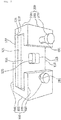
- Fig. 1 is a conceptual diagram schematically showing an X-ray measurement system.
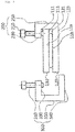
- Fig. 2 is a perspective view showing a battery measurement apparatus using X-rays in accordance with the present invention.
- Fig. 3 is a front view showing the battery measurement apparatus using X-rays in accordance with the present invention.
- Fig. 4 is a rear view showing the battery measurement apparatus using X-rays in accordance with the present invention.
- Fig. 5 is a plan view showing a state in which an auxiliary pressing unit 300 is separated from a first plate 110 and a second plate 120.
- Fig. 6 is a plan view showing a state in which the auxiliary pressing unit 300 is coupled to the first plate 110 and the second plate 120.
- a system to which the battery measurement apparatus using X-rays in accordance with the present invention is applied may irradiate a battery 11 with X-rays by an X-ray light source 13, and receive the X-rays transmitted through the battery 11at a light receiving unit 15 to thereby analyze the battery 11.
- X-rays with a wavelength of 0.56 ⁇ for the analysis of the battery 11 may be used to measure the 2theta range in an effective range.
- the light receiving unit 15 may measure in a range of 5° to 25° of a diffraction angle.
- the battery 11 to be analyzed may include an electrode assembly and a flexible pouch casing for housing the electrode assembly therein.
- an X-ray measurement system may analyze the battery 11 in various states while changing variables such as charging and discharging, temperature, voltage, and so on.
- a gas may be generated in the electrode assembly while the state of the battery 11 changes, and the gas thus generated may expand the pouch casing, thereby interfering with the analysis of the battery 11.
- the battery measurement apparatus using X-rays in accordance with the present invention may be applied to the X-ray measurement system, and more specifically, may be coupled to the battery 11 to suppress changes in the battery 11 due to the internal gas generated in the battery 11.
- the battery measurement apparatus using X-rays may press the battery 11 by making contact with only one face and the other face opposite the one face of the battery 11, and therefore be coupled to the battery 11 regardless of the size of the battery 11.
- one face of the battery 11 is defined as a first battery face 11a, and the other face of the battery 11 opposite the first battery face 11a is defined as a second battery face 11b.
- the battery measurement apparatus using X-rays in accordance with the present invention may comprise a first plate 110 for making contact with the first battery face 11a and pressing the battery 11, a second plate 120 for making contact with the second battery face 11b and supporting the battery 11, and a pressing unit 200 for pressing the first plate 110 toward the second plate 120.
- the battery measurement apparatus using X-rays in accordance with the present invention may be in a state in which the first plate 110 and the second plate 120 make contact with and press only the two opposite faces of the battery 11, and the surfaces of the battery 11 other than the faces pressed by the first plate 110 and the second plate 120 are exposed to the outside. Therefore, the dimensions of the battery 11, except for the faces in contact with the first plate 110 and the second plate 120, may not be limited.
- first plate 110 and the second plate 120 may not transmit X-rays of short wavelengths in regions other than a first hole 115 and a second hole 125.
- first plate 110 and the second plate 120 may be made of a metallic material with high density.
- first plate 110 and the second plate 120 may have excellent properties such as heat resistance, heat dissipation, rigidity, and the like, for use in various analysis environments.
- the first plate 110 and the second plate 120 may be a metal including one or more of Al and SUS.
- the first plate 110 and the second plate 120 may have a thickness of 5 mm to 15 mm. Materials such as Al, SUS, and the like can effectively block X-rays of short wavelengths, with a thickness of 5 mm to 15 mm.
- the first plate 110 may be provided with a first hole 115 formed therein through which X-rays pass
- the second plate 120 may be provided with a second hole 125 formed therein through which X-rays pass
- the first hole 115 and the second hole 125 may be formed at positions facing each other.
- the first hole 115 and the second hole 125 may be formed in a square shape as illustrated in Figs. 3 and 4 .
- the X-ray light source 13 can irradiate a line beam having a length of 20 mm.
- the transverse and longitudinal lengths of the first hole 115 and the second hole 125 may be determined at a level that does not deteriorate the length of the line beam, wavelengths of the X-rays, measurement methods, effective ranges, and the pressing capability. In other words, if the sizes of the first hole 115 and the second hole 125 are smaller, the pressing capability may be excellent, but there may be difficulty in the measurement, and if the sizes are larger, the interferences in the measurement caused by the first plate 110 and the second plate 120 may be reduced, but the pressing capability may be lowered. Therefore, the sizes of the first hole 115 and the second hole 125 may be defined at an appropriate level.
- the longitudinal width of the first hole 115 and the second hole 125 may be 15 mm to 30 mm.
- the transverse width may be preferably similar to the width of the line beam irradiated from the X-rays, and may be 5 mm to 25 mm.
- the first hole 115 and the second hole 125 may be formed with a longitudinal length of 20 mm and a transverse length of 15 mm.
- one face of the first plate 110 for making contact with the battery 11 is defined as a second face 113
- the other face of the first plate 110 opposite the second face 113 is defined as a first face 111
- one face of the second plate 120 for making contact with the battery 11 is defined as a third face 121
- the other face of the second plate 120 opposite the third face 121 is defined as a fourth face 123.
- the pressing unit 200 may comprise a pressing means 210 for pressing the first face of the first plate 110 to thereby cause the second face 113 of the first plate 110 to press the battery 11, a guide plate 230 positioned on the first face 111 side of the first plate 110 and provided with a guide hole 231 into which the pressing means 210 is inserted and guided, and a fixing plate 250 with one end thereof coupled to the second plate 120 and the other end thereof coupled to the guide plate 230, for fixing the second plate 120 and the guide plate 230 parallel to each other while being spaced apart from each other.
- the pressing means 210 may apply a force in a direction in which the first plate 110 moves closer to the second plate 120 in a state where the application point of the force for pressing is located on the guide plate 230.
- the guide hole 231 may also be formed to guide the pressing means 210 in a direction perpendicular to the first battery face 11a.
- the pressing means 210 may be a bolt. Threads may be formed on the inner circumferential surface of the guide hole 231, and the pressing means 210 may be fastened to the guide hole 231 by screw connection.
- the pressing means 210 may be coupled with the guide hole 231 via screw connection by receiving a force with a torque wrench.
- the torque wrench may apply a force of 0 kgfcm to 10 kgfcm or lower or a force of5 kgfcm to 6 kgfcm to the pressing means 210,thereby coupling the pressing means 210 and the guide hole 231 with each other via screw connection.
- the pressing means 210 may be inserted further into the guide hole 231 as the pressing means 210 rotates, the pressing means 210 may extend from the face opposite to the face of the guide plate 230 into which the pressing means 210 is inserted, and the extended end of the pressing means 210 may press the first plate 110.
- the separation distance between the second plate 120 and the guide plate 230 may be 10 mm to 30 mm.
- the lower limit of the distance between the second plate 120 and the guide plate 230 may be set by taking into account the thickness of the first plate 110 and that of the battery 11. Although there is no limitation on the upper limit thereof, it may be considered at the level for preventing the apparatus from being unnecessarily large.
- the first plate 110 may be disposed between the guide plate 230 and the second plate 120 so that the edge of one end of the first plate 110 may make contact with the surface of the fixing plate 250.
- the edge of one end of the first plate 110 may be one of the edges of the first face 111 or the second face 113, and may be an edge that extends further towards the periphery or the portion that extends furthest towards the periphery
- the first hole 115 and the second hole 125 must be aligned.
- the first plate 110 may always have to press in position on the basis of the second plate 120.By aligning the first plate 110 in position with respect to the fixing plate 250 coupled in one body with the second plate 120, the first plate 110 may be aligned in place with respect to the second plate 120. Specifically, by arranging the position of the first hole 115 formed in the first plate 110 on the basis of the edge that makes contact with the fixing plate 250 and by bringing the edge of the first plate 110 into contact with the fixing plate 250, the first hole 115 and the second hole 125 may be aligned.
- the battery measurement apparatus using X-rays in accordance with the present invention may further comprise an auxiliary pressing unit 300 for pressing the first plate 110 and the second plate 120 into close contact with the battery 11 in a position different from that of the pressing unit 200.
- the pressing unit 200 may press the first plate 110 at one end side of the first plate 110
- the auxiliary pressing unit 300 may press the first plate 110 at the other end side of the first plate 110.
- the auxiliary pressing unit 300 may comprise a second auxiliary plate 340 for making contact with the fourth face 123 of the second plate 120 and thereby supporting the second plate 120, a first auxiliary plate 330 facing the first face 111 of the first plate 110 on the first face 111 side, an auxiliary pressing means 310 for insertion into an auxiliary guide hole 331 provided in the first auxiliary plate 330 and for pressing the first plate 110 toward the battery 11, and a column portion 350 with one end thereof coupled to the first auxiliary plate 330 and the other end thereof coupled to the second auxiliary plate 340, for fixing the first auxiliary plate 330 and the second auxiliary plate 340 parallel to each other while being spaced apart from each other.
- the first auxiliary plate 330 and the second auxiliary plate 340 may be parallel to each other and fixed to the column portion 350,and the coupled shape of the first auxiliary plate 330, the second auxiliary plate 340, and the column portion 350 may be a ' ⁇ ' shape as shown in Figs. 5 and 6 .
- the first auxiliary plate 330, the first plate 110, the battery 11, the second plate 120, and the second auxiliary plate 340 may be stacked in this order, and of these, the first auxiliary plate 330, the second auxiliary plate 340, and the column portion 350 may be manufactured as one body.
- the auxiliary pressing unit 300 may have a separate body from the first plate 110, the second plate 120, and the pressing unit 200. Accordingingly, the auxiliary pressing unit 300 may be freely detached from and coupled to the first plate 110 and the second plate 120. The coupling position of the auxiliary pressing unit 300 may be freely set according to the shape and size of the battery 11.
- the auxiliary pressing means 310 may apply a force in a direction in which the first plate 110 moves closer to the second plate 120 in a state where the application point of the force for pressing is located on the first auxiliary plate 330.
- the auxiliary guide hole 331 may also be formed to guide the auxiliary pressing means 310 in a direction perpendicular to the first battery face 11a.
- the auxiliary pressing means 310 may be a bolt. Threads may be formed on the inner circumferential surface of the auxiliary guide hole 331, and the auxiliary pressing means 310 may be fastened to the auxiliary guide hole 331 by screw connection.
- the auxiliary pressing means 310 may be coupled with the auxiliary guide hole 331 via screw connection by receiving a force with a torque wrench.
- the torque wrench may apply a force of 0 kgfcm to 10 kgfcm or lower or a force of 5 kgfcm to 6 kgfcm to the auxiliary pressing means 310, thereby coupling the auxiliary pressing means 310 and the auxiliary guide hole 331 via screw connection.
- the auxiliary pressing means 310 may be inserted further into the auxiliary guide hole 331 as the auxiliary pressing means 310 rotates, the auxiliary pressing means 310 may extend from the face opposite to the face of the first auxiliary plate 330 into which the auxiliary pressing means 310 is inserted, and the extended end of the auxiliary pressing means 310 may press the first plate 110.
- the separation distance between the first auxiliary plate 330 and the second auxiliary plate 340 may be 15 mm to 45 mm.
- the first plate 110, the second plate 120, and the battery 11 may be inserted between the first auxiliary plate 330 and the second auxiliary plate 340, and the distance between the first auxiliary plate 330 and the second auxiliary plate 340 may be determined in consideration of the thicknesses of the first plate 110, the second plate 120, and the battery 11.
- One end of the pressing means 210 and one end of the auxiliary pressing means 310 may make contact with and press the first plate 110 at the same time.
- the first plate 110 may be pressed with two application points.
- an imaginary straight line connecting the point where the pressing means 210 makes contact with the first plate 110 and the point where the auxiliary pressing means 310 makes contact with the first plate 110 may pass through the first hole 115.By setting the pressing positions of the pressing means 210 and the auxiliary pressing means 310 in this way, it is possible to prevent the first plate 110 from being lifted from the battery 11 around the first hole 115.
- the pressing means 210 and the auxiliary pressing means 310 may be coupled to the guide hole 231 and the auxiliary guide hole 331, respectively, via screw connection through a torque wrench, with a force of 3 kgfcm to 5 kgfcm if the battery 11 is of a mono-cell and with a force of 6 kgfcm to 7 kgfcm in the case of bicells.
- the first plate 110 may receive the force from the pressing means 210 and the auxiliary pressing means 310 and press the entire surface area of the battery 10 corresponding to 2450 mm 2 to 2700 mm 2 with uniform pressure.
- the battery measurement apparatus using X-rays in accordance with the present invention can be applied to an X-ray measurement system, and more specifically, can be coupled to a battery to suppress changes in the battery due to the internal gas generated in the battery.
- the battery measurement apparatus using X-rays can press the battery by making contact with only one face and the other face opposite the one face of the battery, and therefore be coupled to the battery regardless of its size.
- the battery measurement apparatus using X-rays in accordance with the present invention only needs to press the required area, it is possible to make contact with and press only part of the surface area of a battery. Therefore, even when a jig is coupled to the battery, the battery can still have exposed areas that are not coupled with the jig, and these exposed areas can be used to connect accessory parts such as a heat-insulating material, a heater, a charge and discharge terminal, and so on, for various analyses.
Landscapes
- Chemical & Material Sciences (AREA)
- Health & Medical Sciences (AREA)
- Pathology (AREA)
- Biochemistry (AREA)
- Immunology (AREA)
- General Physics & Mathematics (AREA)
- General Health & Medical Sciences (AREA)
- Physics & Mathematics (AREA)
- Analytical Chemistry (AREA)
- Life Sciences & Earth Sciences (AREA)
- Crystallography & Structural Chemistry (AREA)
- Engineering & Computer Science (AREA)
- Manufacturing & Machinery (AREA)
- Chemical Kinetics & Catalysis (AREA)
- General Chemical & Material Sciences (AREA)
- Electrochemistry (AREA)
- Multimedia (AREA)
- Nuclear Medicine, Radiotherapy & Molecular Imaging (AREA)
- Radiology & Medical Imaging (AREA)
- Analysing Materials By The Use Of Radiation (AREA)
- Secondary Cells (AREA)
Abstract
Description
- This application claims the benefit of priority to Korean Patent Application No.
10-2019-0050425 filed on April 30, 2019 10-2019-0172991 filed on December 23, 2019 - The present invention is for analyzing the behavior of active materials in a battery in a state where the battery is actually operating in order to check the performance of the active materials, and more particularly, relates to a battery measurement apparatus using X-rays for measuring the battery by transmitting X-rays through the battery.
- In general, a secondary battery is a battery that can be used repetitively through a discharging process for converting chemical energy into electrical energy and a reverse charging process, and types of such secondary batteries include nickel-cadmium (Ni-Cd) batteries, nickel-metal hydride (Ni-MH) batteries, lithium-metal batteries, lithium-ion (Li-ion) batteries, lithium-ion polymer batteries (Li-ion Polymer Battery), and so on. Of these secondary batteries, secondary lithium batteries have been commercialized and widely used because of their high energy density and voltage, a long cycle-life, and a low self-discharge rate.
- Active materials in a battery are materials that actually participate in the reactions at battery electrodes, and the performance of a battery, such as battery capacity and voltage, or the like, may be determined by the performance of the active materials. Therefore, it is important to analyze the active materials in a battery to interpret the performance of the battery.
- Measuring a battery using X-rays may be one of the methods for measuring active materials in the battery. The measurement of a battery may be performed while changing various conditions such as charging and discharging, temperature, voltage, and the like. In such a case, a gas may be generated in the battery, and if the gas generation causes a voltage drop, a pouch swelling phenomenon, or the like, errors may occur in the measurement.
- In order to prevent such a phenomenon, a jig for pressing a battery may be used. However, jigs were required to have the form that conforms to the dimensions and shapes corresponding to the types of secondary batteries sold for a variety of purposes (EV, ESS, cell phone, etc.). In other words, since secondary batteries have diverse dimensions such as surface area, thickness, and so on, it was necessary to replace the jig each time the shape and dimensions of the secondary battery to be inspected are changed in the conventional apparatus.
- Korean Patent Registration No.
10-1274730 - The present invention is designed to analyze the behavior of active materials in a battery in a state where the battery is actually operating in order to check the performance of the active materials, and more particularly, to provide a battery measurement apparatus using X-rays for measuring the battery by transmitting X-rays through the battery.
- The objects sought to be achieved by the present invention are not limited to those set forth above, and other objects that have not been mentioned above will be clearly understood by those having ordinary skill in the art to which the present invention pertains from the following description.
- A battery measurement apparatus using X-rays in accordance with the present invention, when one face of a battery is defined as a first battery face and the other face of the battery opposite the first battery face is defined as a second battery face, the battery measurement apparatus may comprise:, a first plate for making contact with the first battery face and pressing the battery; a second plate for making contact with the second battery face and supporting the battery; and a pressing unit for pressing the first plate toward the second plate, wherein the first plate may be provided with a first hole formed therein through which X-rays pass, the second plate may be provided with a second hole formed therein through which X-rays pass, and the first hole and the second hole may be formed at positions facing each other.
- The battery measurement apparatus using X-rays in accordance with the present invention can be applied to an X-ray measurement system, and more specifically, can be coupled to a battery to suppress changes in the battery due to the internal gas generated in the battery. In addition, the battery measurement apparatus using X-rays can press the battery by making contact with only one face and the other face opposite the one face of the battery, and therefore be coupled to the battery regardless of its size.
- Since the battery measurement apparatus using X-rays in accordance with the present invention only needs to press the required area, it is possible to make contact with and press only part of the surface area of a battery. Therefore, even when a jig is coupled to the battery, the battery can still have exposed areas that are not coupled with the jig, and these exposed areas can be used to connect accessory parts such as a heat-insulating material, a heater, a charge and discharge terminal, and so on, for various analyses.
-
-
Fig. 1 is a conceptual diagram schematically showing an X-ray measurement system; -
Fig. 2 is a perspective view showing a battery measurement apparatus using X-rays in accordance with the present invention; -
Fig. 3 is a front view showing the battery measurement apparatus using X-rays in accordance with the present invention; -
Fig. 4 is a rear view showing the battery measurement apparatus using X-rays in accordance with the present invention; -
Fig. 5 is a plan view showing a state in which an auxiliary pressing unit is separated from a first plate and a second plate; and -
Fig. 6 is a plan view showing a state in which the auxiliary pressing unit is coupled to the first plate and the second plate. - A battery measurement apparatus using X-rays in accordance with the present invention, when one face of a battery is defined as a first battery face and the other face of the battery opposite the first battery face is defined as a second battery face, the battery measurement apparatus may comprise: a first plate for making contact with the first battery face and pressing the battery; a second plate for making contact with the second battery face and supporting the battery; and a pressing unit for pressing the first plate toward the second plate, wherein the first plate may be provided with a first hole formed therein through which X-rays pass, the second plate may be provided with a second hole formed therein through which X-rays pass, and the first hole and the second hole may be formed at positions facing each other.
- In the battery measurement apparatus using X-rays in accordance with the present invention, materials of the first plate and the second plate may comprise one or more of Al and SUS, the first plate and the second plate may have a thickness of 5 mm to 15 mm, and the first hole and the second hole may have a longitudinal width of 15 mm to 30 mm and a transverse width of 5 mm to 25 mm.
- In the battery measurement apparatus using X-rays in accordance with the present invention, when one face of the first plate for making contact with the battery is defined as a second face, the other face of the first plate opposite the second face is defined as a first face, one face of the second plate for making contact with the battery is defined as a third face, and the other face of the second plate opposite the third face is defined as a fourth face, the pressing unit may comprise: a pressing means for pressing the first face of the first plate to thereby cause the second face of the first plate to press the battery; a guide plate positioned on the first face side of the first plate and provided with a guide hole into which the pressing means is inserted and guided; and a fixing plate with one end thereof coupled to the second plate and the other end thereof coupled to the guide plate, for fixing the second plate and the guide plate parallel to each other while being spaced apart from each other.
- In the battery measurement apparatus using X-rays in accordance with the present invention, a separation distance between the second plate and the guide plate may be 10 mm to 30 mm.
- In the battery measurement apparatus using X-rays in accordance with the present invention, the first plate may be disposed between the guide plate and the second plate so that an edge of one end of the first plate makes contact with a surface of the fixing plate.
- The battery measurement apparatus using X-rays in accordance with the present invention, may further comprise an auxiliary pressing unit for pressing the first plate and the second plate into close contact with the battery in a position different from that of the pressing unit.
- In the battery measurement apparatus using X-rays in accordance with the present invention, the auxiliary pressing unit may comprise: a second auxiliary plate for making contact with the fourth face of the second plate and thereby supporting the second plate; a first auxiliary plate facing the first face of the first plate on the first face side; an auxiliary pressing means for insertion into an auxiliary guide hole provided in the first auxiliary plate and for pressing the first plate toward the battery; and a column portion with one end thereof coupled to the first auxiliary plate and the other end thereof coupled to the second auxiliary plate, for fixing the first auxiliary plate and the second auxiliary plate parallel to each other while being spaced apart from each other.
- In the battery measurement apparatus using X-rays in accordance with the present invention, a separation distance between the first auxiliary plate and the second auxiliary plate may be 15 mm to 45 mm.
- In the battery measurement apparatus using X-rays in accordance with the present invention, one end of the pressing means and one end of the auxiliary pressing means may make contact with and press the first plate, and an imaginary straight line connecting the point where the pressing means makes contact with the first plate and the point where the auxiliary pressing means makes contact with the first plate may pass through the first hole.
- Hereinafter, embodiments in accordance with the present invention will be described in detail with reference to the accompanying drawings. During this course of description, the sizes or shapes of the components shown in the drawings may not be made to scale for clarity and convenience of description. In addition, terms that are specifically defined in consideration of the construction and operation of the present invention may vary depending on the convention or intention of a user or operator. Definition of these terms should be made based on the overall contents of the present disclosure.
- In the description of the present invention, it should be noted that the orientation or positional relationship indicated by the terms "central,""up,""down,""left,""right,""vertical,""horizontal,""inward,""outward," etc. are based on the orientation or positional relationship shown in the drawings, or the orientation or positional relationship that is normally presented when using the product of the present invention, and are only for the purpose of explanation and brief description of the invention, and that it is not intended to present or suggest that the apparatus or elements shown must have a specific orientation and be constructed or operated in the specific orientation, and accordingly, it should not be understood to limit the present invention.
- Hereinafter, the construction and functions of a battery measurement apparatus using X-rays in accordance with the present invention will be described in detail, with reference to
Figs. 1 to 6 . -
Fig. 1 is a conceptual diagram schematically showing an X-ray measurement system.Fig. 2 is a perspective view showing a battery measurement apparatus using X-rays in accordance with the present invention.Fig. 3 is a front view showing the battery measurement apparatus using X-rays in accordance with the present invention.Fig. 4 is a rear view showing the battery measurement apparatus using X-rays in accordance with the present invention.Fig. 5 is a plan view showing a state in which an auxiliarypressing unit 300 is separated from afirst plate 110 and asecond plate 120.Fig. 6 is a plan view showing a state in which the auxiliarypressing unit 300 is coupled to thefirst plate 110 and thesecond plate 120. - As illustrated in
Fig. 1 , a system to which the battery measurement apparatus using X-rays in accordance with the present invention is applied may irradiate a battery 11 with X-rays by an X-ray light source 13, and receive the X-rays transmitted through the battery 11at a light receiving unit 15 to thereby analyze the battery 11.For example, in the 2theta scan measurement method, X-rays with a wavelength of 0.56 Å for the analysis of the battery 11 may be used to measure the 2theta range in an effective range. The light receiving unit 15 may measure in a range of 5° to 25° of a diffraction angle. - The battery 11 to be analyzed may include an electrode assembly and a flexible pouch casing for housing the electrode assembly therein. In the analysis of the battery 11, an X-ray measurement system may analyze the battery 11 in various states while changing variables such as charging and discharging, temperature, voltage, and so on. In the case of the flexible pouch casing, a gas may be generated in the electrode assembly while the state of the battery 11 changes, and the gas thus generated may expand the pouch casing, thereby interfering with the analysis of the battery 11.
- The battery measurement apparatus using X-rays in accordance with the present invention may be applied to the X-ray measurement system, and more specifically, may be coupled to the battery 11 to suppress changes in the battery 11 due to the internal gas generated in the battery 11.In addition, the battery measurement apparatus using X-rays may press the battery 11 by making contact with only one face and the other face opposite the one face of the battery 11, and therefore be coupled to the battery 11 regardless of the size of the battery 11.
- For the following description, one face of the battery 11 is defined as a
first battery face 11a, and the other face of the battery 11 opposite thefirst battery face 11a is defined as asecond battery face 11b. - As shown in
Fig. 2 , the battery measurement apparatus using X-rays in accordance with the present invention may comprise afirst plate 110 for making contact with thefirst battery face 11a and pressing the battery 11, asecond plate 120 for making contact with thesecond battery face 11b and supporting the battery 11, and apressing unit 200 for pressing thefirst plate 110 toward thesecond plate 120. In other words, the battery measurement apparatus using X-rays in accordance with the present invention may be in a state in which thefirst plate 110 and thesecond plate 120 make contact with and press only the two opposite faces of the battery 11, and the surfaces of the battery 11 other than the faces pressed by thefirst plate 110 and thesecond plate 120 are exposed to the outside. Therefore, the dimensions of the battery 11, except for the faces in contact with thefirst plate 110 and thesecond plate 120, may not be limited. - It may be desirable for the
first plate 110 and thesecond plate 120 not to transmit X-rays of short wavelengths in regions other than afirst hole 115 and a second hole 125.Therefore, it may be desirable for thefirst plate 110 and thesecond plate 120 to be made of a metallic material with high density. In addition, it may be desirable for thefirst plate 110 and thesecond plate 120 to have excellent properties such as heat resistance, heat dissipation, rigidity, and the like, for use in various analysis environments. Accordingly, thefirst plate 110 and thesecond plate 120 may be a metal including one or more of Al and SUS. Thefirst plate 110 and thesecond plate 120 may have a thickness of 5 mm to 15 mm. Materials such as Al, SUS, and the like can effectively block X-rays of short wavelengths, with a thickness of 5 mm to 15 mm. - The
first plate 110 may be provided with afirst hole 115 formed therein through which X-rays pass, thesecond plate 120 may be provided with asecond hole 125 formed therein through which X-rays pass, and thefirst hole 115 and thesecond hole 125 may be formed at positions facing each other. For example, thefirst hole 115 and thesecond hole 125 may be formed in a square shape as illustrated inFigs. 3 and 4 . In the system to which the battery measurement apparatus using X-rays in accordance with the present invention is applied, the X-ray light source 13 can irradiate a line beam having a length of 20 mm. The transverse and longitudinal lengths of thefirst hole 115 and thesecond hole 125 may be determined at a level that does not deteriorate the length of the line beam, wavelengths of the X-rays, measurement methods, effective ranges, and the pressing capability. In other words, if the sizes of thefirst hole 115 and thesecond hole 125 are smaller, the pressing capability may be excellent, but there may be difficulty in the measurement, and if the sizes are larger, the interferences in the measurement caused by thefirst plate 110 and thesecond plate 120 may be reduced, but the pressing capability may be lowered. Therefore, the sizes of thefirst hole 115 and thesecond hole 125 may be defined at an appropriate level. - Specifically, in order to advantageously obtain an effective 2theta range (2theta of 5° to 25°) in the 2theta scan measurement method when the wavelength of the X-rays is less than 0.6 Å, the longitudinal width of the
first hole 115 and thesecond hole 125 may be 15 mm to 30 mm. The transverse width may be preferably similar to the width of the line beam irradiated from the X-rays, and may be 5 mm to 25 mm. For example, thefirst hole 115 and thesecond hole 125 may be formed with a longitudinal length of 20 mm and a transverse length of 15 mm. - For description, one face of the
first plate 110 for making contact with the battery 11 is defined as asecond face 113, the other face of thefirst plate 110 opposite thesecond face 113 is defined as afirst face 111, one face of thesecond plate 120 for making contact with the battery 11 is defined as athird face 121, and the other face of thesecond plate 120 opposite thethird face 121 is defined as afourth face 123. - As shown in
Figs. 5 and6 ,thepressing unit 200 may comprise apressing means 210 for pressing the first face of thefirst plate 110 to thereby cause thesecond face 113 of thefirst plate 110 to press the battery 11, aguide plate 230 positioned on thefirst face 111 side of thefirst plate 110 and provided with aguide hole 231 into which thepressing means 210 is inserted and guided, and a fixingplate 250 with one end thereof coupled to thesecond plate 120 and the other end thereof coupled to theguide plate 230, for fixing thesecond plate 120 and theguide plate 230 parallel to each other while being spaced apart from each other. - In other words, the
second plate 120 and theguide plate 230 may be parallel to each other and fixed to the fixingplate 250, and the coupled shape of thesecond plate 120, theguide plate 230, and the fixingplate 250 may be a'□' shape as shown inFigs. 5 and6 . Theguide plate 230, thefirst plate 110, the battery 11, andsecond plate 120 may be stacked in this order, and of these, theguide plate 230, thesecond plate 120, and the fixingplate 250 may be manufactured as one body. The pressing means 210 may apply a force in a direction in which thefirst plate 110 moves closer to thesecond plate 120 in a state where the application point of the force for pressing is located on the guide plate 230.Therefore, theguide hole 231 may also be formed to guide the pressing means 210 in a direction perpendicular to thefirst battery face 11a. For example, the pressing means 210 may be a bolt. Threads may be formed on the inner circumferential surface of theguide hole 231, and thepressing means 210 may be fastened to theguide hole 231 by screw connection. Specifically, the pressing means 210 may be coupled with theguide hole 231 via screw connection by receiving a force with a torque wrench. The torque wrench may apply a force of 0 kgfcm to 10 kgfcm or lower or a force of5 kgfcm to 6 kgfcm to thepressing means 210,thereby coupling thepressing means 210 and theguide hole 231 with each other via screw connection. - In other words, the pressing means 210 may be inserted further into the
guide hole 231 as the pressing means 210 rotates, the pressing means 210 may extend from the face opposite to the face of theguide plate 230 into which thepressing means 210 is inserted, and the extended end of thepressing means 210 may press thefirst plate 110. - The separation distance between the
second plate 120 and theguide plate 230 may be 10 mm to 30 mm. The lower limit of the distance between thesecond plate 120 and theguide plate 230 may be set by taking into account the thickness of thefirst plate 110 and that of the battery 11. Although there is no limitation on the upper limit thereof, it may be considered at the level for preventing the apparatus from being unnecessarily large. - The
first plate 110 may be disposed between theguide plate 230 and thesecond plate 120 so that the edge of one end of thefirst plate 110 may make contact with the surface of the fixing plate 250.The edge of one end of thefirst plate 110 may be one of the edges of thefirst face 111 or thesecond face 113, and may be an edge that extends further towards the periphery or the portion that extends furthest towards the periphery In order for the X-rays outputted from the X-ray light source 13 to reach the light receiving unit 15, thefirst hole 115 and thesecond hole 125 must be aligned. Therefore, thefirst plate 110 may always have to press in position on the basis of the second plate 120.By aligning thefirst plate 110 in position with respect to the fixingplate 250 coupled in one body with thesecond plate 120, thefirst plate 110 may be aligned in place with respect to thesecond plate 120. Specifically, by arranging the position of thefirst hole 115 formed in thefirst plate 110 on the basis of the edge that makes contact with the fixingplate 250 and by bringing the edge of thefirst plate 110 into contact with the fixingplate 250, thefirst hole 115 and thesecond hole 125 may be aligned. - As shown in
Figs. 5 and6 , the battery measurement apparatus using X-rays in accordance with the present invention may further comprise an auxiliarypressing unit 300 for pressing thefirst plate 110 and thesecond plate 120 into close contact with the battery 11 in a position different from that of the pressing unit 200.For example, thepressing unit 200 may press thefirst plate 110 at one end side of thefirst plate 110, and the auxiliarypressing unit 300 may press thefirst plate 110 at the other end side of thefirst plate 110. - The auxiliary
pressing unit 300 may comprise a secondauxiliary plate 340 for making contact with thefourth face 123 of thesecond plate 120 and thereby supporting thesecond plate 120, a firstauxiliary plate 330 facing thefirst face 111 of thefirst plate 110 on thefirst face 111 side, an auxiliarypressing means 310 for insertion into anauxiliary guide hole 331 provided in the firstauxiliary plate 330 and for pressing thefirst plate 110 toward the battery 11, and acolumn portion 350 with one end thereof coupled to the firstauxiliary plate 330 and the other end thereof coupled to the secondauxiliary plate 340, for fixing the firstauxiliary plate 330 and the secondauxiliary plate 340 parallel to each other while being spaced apart from each other. - The first
auxiliary plate 330 and the secondauxiliary plate 340 may be parallel to each other and fixed to thecolumn portion 350,and the coupled shape of the firstauxiliary plate 330, the secondauxiliary plate 340, and thecolumn portion 350 may be a '□' shape as shown inFigs. 5 and6 . The firstauxiliary plate 330, thefirst plate 110, the battery 11, thesecond plate 120, and the secondauxiliary plate 340 may be stacked in this order, and of these, the firstauxiliary plate 330, the secondauxiliary plate 340, and thecolumn portion 350 may be manufactured as one body. The auxiliarypressing unit 300 may have a separate body from thefirst plate 110, thesecond plate 120, and the pressing unit 200.Accordingly, the auxiliarypressing unit 300 may be freely detached from and coupled to thefirst plate 110 and the second plate 120.The coupling position of the auxiliarypressing unit 300 may be freely set according to the shape and size of the battery 11. - The auxiliary
pressing means 310 may apply a force in a direction in which thefirst plate 110 moves closer to thesecond plate 120 in a state where the application point of the force for pressing is located on the first auxiliary plate 330.Therefore, theauxiliary guide hole 331 may also be formed to guide the auxiliarypressing means 310 in a direction perpendicular to the first battery face 11a.For example, the auxiliarypressing means 310 may be a bolt. Threads may be formed on the inner circumferential surface of theauxiliary guide hole 331, and the auxiliarypressing means 310 may be fastened to theauxiliary guide hole 331 by screw connection. Specifically, the auxiliarypressing means 310 may be coupled with theauxiliary guide hole 331 via screw connection by receiving a force with a torque wrench. The torque wrench may apply a force of 0 kgfcm to 10 kgfcm or lower or a force of 5 kgfcm to 6 kgfcm to the auxiliarypressing means 310, thereby coupling the auxiliarypressing means 310 and theauxiliary guide hole 331 via screw connection. - In other words, the auxiliary
pressing means 310 may be inserted further into theauxiliary guide hole 331 as the auxiliarypressing means 310 rotates, the auxiliarypressing means 310 may extend from the face opposite to the face of the firstauxiliary plate 330 into which the auxiliarypressing means 310 is inserted, and the extended end of the auxiliarypressing means 310 may press thefirst plate 110. - The separation distance between the first
auxiliary plate 330 and the secondauxiliary plate 340 may be 15 mm to 45 mm. Thefirst plate 110, thesecond plate 120, and the battery 11 may be inserted between the firstauxiliary plate 330 and the secondauxiliary plate 340, and the distance between the firstauxiliary plate 330 and the secondauxiliary plate 340 may be determined in consideration of the thicknesses of thefirst plate 110, thesecond plate 120, and the battery 11. - One end of the
pressing means 210 and one end of the auxiliarypressing means 310 may make contact with and press thefirst plate 110 at the same time. In other words, thefirst plate 110 may be pressed with two application points. - As shown in
Fig. 3 , an imaginary straight line connecting the point where thepressing means 210 makes contact with thefirst plate 110 and the point where the auxiliarypressing means 310 makes contact with thefirst plate 110 may pass through the first hole 115.By setting the pressing positions of thepressing means 210 and the auxiliarypressing means 310 in this way, it is possible to prevent thefirst plate 110 from being lifted from the battery 11 around thefirst hole 115. - The pressing means 210 and the auxiliary
pressing means 310 may be coupled to theguide hole 231 and theauxiliary guide hole 331, respectively, via screw connection through a torque wrench, with a force of 3 kgfcm to 5 kgfcm if the battery 11 is of a mono-cell and with a force of 6 kgfcm to 7 kgfcm in the case of bicells. - While the ends of the
pressing mean 210 and the auxiliarypressing means 310 exert a force on thefirst plate 110 at two points, thefirst plate 110 may receive the force from thepressing means 210 and the auxiliarypressing means 310 and press the entire surface area of the battery 10 corresponding to 2450 mm2 to 2700 mm2 with uniform pressure. - While the embodiments in accordance with the present invention have been described above, they are only for illustration and those having ordinary skill in the art to which the present invention pertains will appreciate that various modifications and equivalent embodiments can be made therefrom. Therefore, the true scope of the technical protection of the present invention should be defined by the following claims.
- The battery measurement apparatus using X-rays in accordance with the present invention can be applied to an X-ray measurement system, and more specifically, can be coupled to a battery to suppress changes in the battery due to the internal gas generated in the battery. In addition, the battery measurement apparatus using X-rays can press the battery by making contact with only one face and the other face opposite the one face of the battery, and therefore be coupled to the battery regardless of its size.
- Since the battery measurement apparatus using X-rays in accordance with the present invention only needs to press the required area, it is possible to make contact with and press only part of the surface area of a battery. Therefore, even when a jig is coupled to the battery, the battery can still have exposed areas that are not coupled with the jig, and these exposed areas can be used to connect accessory parts such as a heat-insulating material, a heater, a charge and discharge terminal, and so on, for various analyses.
Claims (9)
- A battery measurement apparatus using X-rays,
when one face of a battery is defined as a first battery face and the other face of the battery opposite the first battery face is defined as a second battery face,
the battery measurement apparatus comprising:a first plate for making contact with the first battery face and pressing the battery;a second plate for making contact with the second battery face and supporting the battery; anda pressing unit for pressing the first plate toward the second plate, whereinthe first plate is provided with a first hole formed therein through which X-rays pass,the second plate is provided with a second hole formed therein through which X-rays pass, andthe first hole and the second hole are formed at positions facing each other. - The battery measurement apparatus using X-rays of claim 1, wherein materials of the first plate and the second plate comprise one or more of Al and SUS,
the first plate and the second plate have a thickness of 5 mm to 15 mm, and
the first hole and the second hole have a longitudinal width of 15 mm to 30 mm and a transverse width of 5 mm to 25 mm. - The battery measurement apparatus using X-rays of claim 1, wherein when one face of the first plate for making contact with the battery is defined as a second face,
the other face of the first plate opposite the second face is defined as a first face,
one face of the second plate for making contact with the battery is defined as a third face, and
the other face of the second plate opposite the third face is defined as a fourth face,
the pressing unit comprises:a pressing means for pressing the first face of the first plate to thereby cause the second face of the first plate to press the battery;a guide plate positioned on first face side of the first plate and provided with a guide hole into which the pressing means is inserted and by which the pressing means is guided; anda fixing plate with one end thereof coupled to the second plate and the other end thereof coupled to the guide plate, for fixing the second plate and the guide plate parallel to each other while being spaced apart from each other. - The battery measurement apparatus using X-rays of claim 3, wherein a separation distance between the second plate and the guide plate is 10 mm to 30 mm.
- The battery measurement apparatus using X-rays of claim 3, wherein the first plate is disposed between the guide plate and the second plate so that an edge of one end of the first plate makes contact with a surface of the fixing plate.
- The battery measurement apparatus using X-rays of claim 3, further comprising:
an auxiliary pressing unit for pressing the first plate and the second plate into close contact with the battery in a position different from that of the pressing unit. - The battery measurement apparatus using X-rays of claim 6, wherein the auxiliary pressing unit comprises:a second auxiliary plate for making contact with the fourth face of the second plate and thereby supporting the second plate;a first auxiliary plate facing the first face of the first plate on the first face side;an auxiliary pressing means for insertion into an auxiliary guide hole provided in the first auxiliary plate and for pressing the first plate toward the battery; anda column portion with one end thereof coupled to the first auxiliary plate and the other end thereof coupled to the second auxiliary plate, for fixing the first auxiliary plate and the second auxiliary plate parallel to each other while being spaced apart from each other.
- The battery measurement apparatus using X-rays of claim 7, wherein a separation distance between the first auxiliary plate and the second auxiliary plate is 15 mm to 45 mm.
- The battery measurement apparatus using X-rays of claim 7, wherein one end of the pressing means and one end of the auxiliary pressing means make contact with and press the first plate, and
an imaginary straight line connecting the point where the pressing means makes contact with the first plate and the point where the auxiliary pressing means makes contact with the first plate passes through the first hole.
Applications Claiming Priority (3)
| Application Number | Priority Date | Filing Date | Title |
|---|---|---|---|
| KR20190050425 | 2019-04-30 | ||
| KR1020190172991A KR102395889B1 (en) | 2019-04-30 | 2019-12-23 | Apparatus for measuring cell using x-ray |
| PCT/KR2020/002712 WO2020222413A1 (en) | 2019-04-30 | 2020-02-26 | Battery measurement apparatus using x-rays |
Publications (3)
| Publication Number | Publication Date |
|---|---|
| EP3805743A1 true EP3805743A1 (en) | 2021-04-14 |
| EP3805743A4 EP3805743A4 (en) | 2021-09-22 |
| EP3805743B1 EP3805743B1 (en) | 2023-07-19 |
Family
ID=73429303
Family Applications (1)
| Application Number | Title | Priority Date | Filing Date |
|---|---|---|---|
| EP20799321.3A Active EP3805743B1 (en) | 2019-04-30 | 2020-02-26 | Battery measurement apparatus using x-rays |
Country Status (7)
| Country | Link |
|---|---|
| EP (1) | EP3805743B1 (en) |
| JP (1) | JP7152071B2 (en) |
| KR (1) | KR102395889B1 (en) |
| CN (1) | CN112384791B (en) |
| ES (1) | ES2955813T3 (en) |
| HU (1) | HUE063295T2 (en) |
| PL (1) | PL3805743T3 (en) |
Families Citing this family (1)
| Publication number | Priority date | Publication date | Assignee | Title |
|---|---|---|---|---|
| KR102677855B1 (en) * | 2022-11-28 | 2024-06-25 | (주)미래컴퍼니 | Method and device for manufacturing all-solid state battery |
Family Cites Families (17)
| Publication number | Priority date | Publication date | Assignee | Title |
|---|---|---|---|---|
| JP3907120B2 (en) * | 2004-02-05 | 2007-04-18 | 株式会社リガク | Sample support device for X-ray analysis and X-ray analysis device |
| JP5028588B2 (en) * | 2006-09-04 | 2012-09-19 | 公益財団法人名古屋産業科学研究所 | Structure analysis method of soft material by beam irradiation and soft material holding device used therefor |
| KR101334121B1 (en) * | 2009-10-26 | 2013-11-29 | 에스케이이노베이션 주식회사 | Electrode Inspection Device for Battery and Method of the Same. |
| JP2012159311A (en) * | 2011-01-29 | 2012-08-23 | Rigaku Corp | X-ray measurement battery structure and support device therefor |
| CN102435625B (en) * | 2011-12-27 | 2016-05-18 | 东莞新能源科技有限公司 | A kind of X-ray diffraction home position testing method and specimen holder |
| KR101274730B1 (en) | 2012-10-11 | 2013-06-17 | 군산대학교산학협력단 | In situ battery frame for measuring x-ray diffraction |
| KR102193268B1 (en) * | 2013-03-14 | 2020-12-23 | 에네베이트 코포레이션 | Clamping device for an electrochemical cell stack |
| JP6221723B2 (en) * | 2013-12-17 | 2017-11-01 | 住友金属鉱山株式会社 | X-ray analyzer and X-ray analysis method |
| JP6406077B2 (en) * | 2015-03-13 | 2018-10-17 | 住友金属鉱山株式会社 | Sample holder and X-ray analysis method |
| CN205352967U (en) * | 2015-11-04 | 2016-06-29 | 中国科学院上海微系统与信息技术研究所 | Lithium ion battery's in situ test device and equipment support |
| KR20170116539A (en) * | 2016-04-11 | 2017-10-19 | 주식회사 엘지화학 | Vertical resistance measurement device of lithium-sulfur battery and method for evaluating cathode of lithium-sulfur battery using the same |
| JP2018049002A (en) * | 2016-09-16 | 2018-03-29 | 住友金属鉱山株式会社 | Sample holder and X-ray analysis method |
| JP6673165B2 (en) * | 2016-11-29 | 2020-03-25 | 株式会社島津製作所 | X-ray inspection equipment for batteries |
| KR101971158B1 (en) * | 2017-09-07 | 2019-08-27 | 한국과학기술연구원 | In situ coin cell supporting device for transmission mode x-ray diffractometry with capable of controlling temperature |
| EP3460893B1 (en) * | 2017-09-21 | 2020-01-08 | Helmholtz-Zentrum Geesthacht Zentrum für Material- und Küstenforschung GmbH | Device for gripping and tempering of flat specimens for x-ray diffractometry |
| CN207600984U (en) * | 2018-02-28 | 2018-07-10 | 北京中研环科科技有限公司 | Secondary cell X-ray absorption fluorescent in situ reaction tank |
| KR101959004B1 (en) * | 2018-05-09 | 2019-03-15 | 한전원자력연료 주식회사 | Complementing apparatus for spent nuclear fuel with quad rod |
-
2019
- 2019-12-23 KR KR1020190172991A patent/KR102395889B1/en active Active
-
2020
- 2020-02-26 CN CN202080003954.1A patent/CN112384791B/en active Active
- 2020-02-26 JP JP2021500117A patent/JP7152071B2/en active Active
- 2020-02-26 EP EP20799321.3A patent/EP3805743B1/en active Active
- 2020-02-26 HU HUE20799321A patent/HUE063295T2/en unknown
- 2020-02-26 PL PL20799321.3T patent/PL3805743T3/en unknown
- 2020-02-26 ES ES20799321T patent/ES2955813T3/en active Active
Also Published As
| Publication number | Publication date |
|---|---|
| KR102395889B1 (en) | 2022-05-09 |
| HUE063295T2 (en) | 2024-01-28 |
| ES2955813T3 (en) | 2023-12-07 |
| CN112384791A (en) | 2021-02-19 |
| PL3805743T3 (en) | 2023-12-11 |
| CN112384791B (en) | 2024-12-17 |
| EP3805743B1 (en) | 2023-07-19 |
| JP2021530682A (en) | 2021-11-11 |
| KR20200126885A (en) | 2020-11-09 |
| EP3805743A4 (en) | 2021-09-22 |
| JP7152071B2 (en) | 2022-10-12 |
Similar Documents
| Publication | Publication Date | Title |
|---|---|---|
| CN110998902B (en) | Battery module and method of manufacturing the same | |
| EP2869361B1 (en) | Sealing tool for pouch-type secondary battery | |
| EP3605662B1 (en) | Apparatus for bending current breaking member of battery pack | |
| KR101451731B1 (en) | Battery Cell Charge-Discharge Device with Novel Structure | |
| EP2083464B1 (en) | Lithium secondary battery | |
| US20160204481A1 (en) | Secondary battery | |
| EP3813180B1 (en) | Secondary-battery internal gas collecting apparatus | |
| CN113348575B (en) | Equipment and method for manufacturing secondary battery | |
| KR20190132906A (en) | Apparatus for collecting inner gas in secondary electric cell and method thereof for charging and discharging | |
| JP6406077B2 (en) | Sample holder and X-ray analysis method | |
| KR101802926B1 (en) | Battery having Sensing Assembly Structure for Processing Signal of Cell | |
| KR20100070194A (en) | Dismantler of cylindrical secondary battery | |
| KR102011113B1 (en) | Battery module, battery pack comprising the battery module and vehicle comprising the battery pack | |
| KR102952237B1 (en) | Battery cell internal pressure measuring apparatus | |
| EP3805743B1 (en) | Battery measurement apparatus using x-rays | |
| KR102525643B1 (en) | Pressurizing/heating device for battery cell activation | |
| KR102145107B1 (en) | Apparatus for collecting inner gas in secondary electric cell and method thereof | |
| KR20200049123A (en) | Battery module including Temperature Measurement Device | |
| KR20150069898A (en) | Rechargeable battery having insulation case | |
| KR102814177B1 (en) | A pouch for analyzing the swelling characteristics of the battery cells and methods of analyzing the battery cells using the same | |
| KR101256951B1 (en) | Apparatus for compressing side of the same | |
| KR20080082347A (en) | Battery module and its manufacturing method | |
| KR102876794B1 (en) | Tray for unidirectional battery cells | |
| KR101738600B1 (en) | Jig for charge and recharge of lithium secondary battery and apparatus utilizing it | |
| CN109154488B (en) | Device for measuring thickness change of electrode of secondary battery and secondary battery in which the device is installed |
Legal Events
| Date | Code | Title | Description |
|---|---|---|---|
| STAA | Information on the status of an ep patent application or granted ep patent |
Free format text: STATUS: THE INTERNATIONAL PUBLICATION HAS BEEN MADE |
|
| PUAI | Public reference made under article 153(3) epc to a published international application that has entered the european phase |
Free format text: ORIGINAL CODE: 0009012 |
|
| STAA | Information on the status of an ep patent application or granted ep patent |
Free format text: STATUS: REQUEST FOR EXAMINATION WAS MADE |
|
| 17P | Request for examination filed |
Effective date: 20210105 |
|
| AK | Designated contracting states |
Kind code of ref document: A1 Designated state(s): AL AT BE BG CH CY CZ DE DK EE ES FI FR GB GR HR HU IE IS IT LI LT LU LV MC MK MT NL NO PL PT RO RS SE SI SK SM TR |
|
| AX | Request for extension of the european patent |
Extension state: BA ME |
|
| A4 | Supplementary search report drawn up and despatched |
Effective date: 20210819 |
|
| RIC1 | Information provided on ipc code assigned before grant |
Ipc: G01N 23/205 20180101ALI20210813BHEP Ipc: H01M 10/48 20060101ALI20210813BHEP Ipc: G01N 23/04 20180101ALI20210813BHEP Ipc: G01N 23/20025 20180101AFI20210813BHEP |
|
| RAP1 | Party data changed (applicant data changed or rights of an application transferred) |
Owner name: LG ENERGY SOLUTION LTD. |
|
| RAP3 | Party data changed (applicant data changed or rights of an application transferred) |
Owner name: LG ENERGY SOLUTION, LTD. |
|
| DAV | Request for validation of the european patent (deleted) | ||
| DAX | Request for extension of the european patent (deleted) | ||
| REG | Reference to a national code |
Ref country code: DE Ref legal event code: R079 Ipc: H01M0010420000 Ref country code: DE Ref legal event code: R079 Ref document number: 602020014184 Country of ref document: DE Free format text: PREVIOUS MAIN CLASS: G01N0023200250 Ipc: H01M0010420000 |
|
| GRAP | Despatch of communication of intention to grant a patent |
Free format text: ORIGINAL CODE: EPIDOSNIGR1 |
|
| STAA | Information on the status of an ep patent application or granted ep patent |
Free format text: STATUS: GRANT OF PATENT IS INTENDED |
|
| RIC1 | Information provided on ipc code assigned before grant |
Ipc: H01M 10/48 20060101ALI20230223BHEP Ipc: G01N 23/205 20060101ALI20230223BHEP Ipc: G01N 23/20025 20180101ALI20230223BHEP Ipc: H01M 10/42 20060101AFI20230223BHEP |
|
| INTG | Intention to grant announced |
Effective date: 20230317 |
|
| GRAS | Grant fee paid |
Free format text: ORIGINAL CODE: EPIDOSNIGR3 |
|
| GRAA | (expected) grant |
Free format text: ORIGINAL CODE: 0009210 |
|
| STAA | Information on the status of an ep patent application or granted ep patent |
Free format text: STATUS: THE PATENT HAS BEEN GRANTED |
|
| P01 | Opt-out of the competence of the unified patent court (upc) registered |
Effective date: 20230519 |
|
| AK | Designated contracting states |
Kind code of ref document: B1 Designated state(s): AL AT BE BG CH CY CZ DE DK EE ES FI FR GB GR HR HU IE IS IT LI LT LU LV MC MK MT NL NO PL PT RO RS SE SI SK SM TR |
|
| REG | Reference to a national code |
Ref country code: GB Ref legal event code: FG4D |
|
| REG | Reference to a national code |
Ref country code: CH Ref legal event code: EP |
|
| REG | Reference to a national code |
Ref country code: DE Ref legal event code: R096 Ref document number: 602020014184 Country of ref document: DE |
|
| REG | Reference to a national code |
Ref country code: IE Ref legal event code: FG4D |
|
| REG | Reference to a national code |
Ref country code: SE Ref legal event code: TRGR |
|
| REG | Reference to a national code |
Ref country code: LT Ref legal event code: MG9D |
|
| REG | Reference to a national code |
Ref country code: NL Ref legal event code: MP Effective date: 20230719 |
|
| REG | Reference to a national code |
Ref country code: ES Ref legal event code: FG2A Ref document number: 2955813 Country of ref document: ES Kind code of ref document: T3 Effective date: 20231207 |
|
| REG | Reference to a national code |
Ref country code: AT Ref legal event code: MK05 Ref document number: 1590394 Country of ref document: AT Kind code of ref document: T Effective date: 20230719 |
|
| PG25 | Lapsed in a contracting state [announced via postgrant information from national office to epo] |
Ref country code: NL Free format text: LAPSE BECAUSE OF FAILURE TO SUBMIT A TRANSLATION OF THE DESCRIPTION OR TO PAY THE FEE WITHIN THE PRESCRIBED TIME-LIMIT Effective date: 20230719 |
|
| PG25 | Lapsed in a contracting state [announced via postgrant information from national office to epo] |
Ref country code: GR Free format text: LAPSE BECAUSE OF FAILURE TO SUBMIT A TRANSLATION OF THE DESCRIPTION OR TO PAY THE FEE WITHIN THE PRESCRIBED TIME-LIMIT Effective date: 20231020 |
|
| PG25 | Lapsed in a contracting state [announced via postgrant information from national office to epo] |
Ref country code: IS Free format text: LAPSE BECAUSE OF FAILURE TO SUBMIT A TRANSLATION OF THE DESCRIPTION OR TO PAY THE FEE WITHIN THE PRESCRIBED TIME-LIMIT Effective date: 20231119 |
|
| REG | Reference to a national code |
Ref country code: HU Ref legal event code: AG4A Ref document number: E063295 Country of ref document: HU |
|
| PG25 | Lapsed in a contracting state [announced via postgrant information from national office to epo] |
Ref country code: RS Free format text: LAPSE BECAUSE OF FAILURE TO SUBMIT A TRANSLATION OF THE DESCRIPTION OR TO PAY THE FEE WITHIN THE PRESCRIBED TIME-LIMIT Effective date: 20230719 Ref country code: PT Free format text: LAPSE BECAUSE OF FAILURE TO SUBMIT A TRANSLATION OF THE DESCRIPTION OR TO PAY THE FEE WITHIN THE PRESCRIBED TIME-LIMIT Effective date: 20231120 Ref country code: NO Free format text: LAPSE BECAUSE OF FAILURE TO SUBMIT A TRANSLATION OF THE DESCRIPTION OR TO PAY THE FEE WITHIN THE PRESCRIBED TIME-LIMIT Effective date: 20231019 Ref country code: LV Free format text: LAPSE BECAUSE OF FAILURE TO SUBMIT A TRANSLATION OF THE DESCRIPTION OR TO PAY THE FEE WITHIN THE PRESCRIBED TIME-LIMIT Effective date: 20230719 Ref country code: LT Free format text: LAPSE BECAUSE OF FAILURE TO SUBMIT A TRANSLATION OF THE DESCRIPTION OR TO PAY THE FEE WITHIN THE PRESCRIBED TIME-LIMIT Effective date: 20230719 Ref country code: IS Free format text: LAPSE BECAUSE OF FAILURE TO SUBMIT A TRANSLATION OF THE DESCRIPTION OR TO PAY THE FEE WITHIN THE PRESCRIBED TIME-LIMIT Effective date: 20231119 Ref country code: HR Free format text: LAPSE BECAUSE OF FAILURE TO SUBMIT A TRANSLATION OF THE DESCRIPTION OR TO PAY THE FEE WITHIN THE PRESCRIBED TIME-LIMIT Effective date: 20230719 Ref country code: GR Free format text: LAPSE BECAUSE OF FAILURE TO SUBMIT A TRANSLATION OF THE DESCRIPTION OR TO PAY THE FEE WITHIN THE PRESCRIBED TIME-LIMIT Effective date: 20231020 Ref country code: FI Free format text: LAPSE BECAUSE OF FAILURE TO SUBMIT A TRANSLATION OF THE DESCRIPTION OR TO PAY THE FEE WITHIN THE PRESCRIBED TIME-LIMIT Effective date: 20230719 Ref country code: AT Free format text: LAPSE BECAUSE OF FAILURE TO SUBMIT A TRANSLATION OF THE DESCRIPTION OR TO PAY THE FEE WITHIN THE PRESCRIBED TIME-LIMIT Effective date: 20230719 |
|
| REG | Reference to a national code |
Ref country code: DE Ref legal event code: R097 Ref document number: 602020014184 Country of ref document: DE |
|
| PG25 | Lapsed in a contracting state [announced via postgrant information from national office to epo] |
Ref country code: SM Free format text: LAPSE BECAUSE OF FAILURE TO SUBMIT A TRANSLATION OF THE DESCRIPTION OR TO PAY THE FEE WITHIN THE PRESCRIBED TIME-LIMIT Effective date: 20230719 Ref country code: RO Free format text: LAPSE BECAUSE OF FAILURE TO SUBMIT A TRANSLATION OF THE DESCRIPTION OR TO PAY THE FEE WITHIN THE PRESCRIBED TIME-LIMIT Effective date: 20230719 Ref country code: EE Free format text: LAPSE BECAUSE OF FAILURE TO SUBMIT A TRANSLATION OF THE DESCRIPTION OR TO PAY THE FEE WITHIN THE PRESCRIBED TIME-LIMIT Effective date: 20230719 Ref country code: DK Free format text: LAPSE BECAUSE OF FAILURE TO SUBMIT A TRANSLATION OF THE DESCRIPTION OR TO PAY THE FEE WITHIN THE PRESCRIBED TIME-LIMIT Effective date: 20230719 Ref country code: CZ Free format text: LAPSE BECAUSE OF FAILURE TO SUBMIT A TRANSLATION OF THE DESCRIPTION OR TO PAY THE FEE WITHIN THE PRESCRIBED TIME-LIMIT Effective date: 20230719 Ref country code: SK Free format text: LAPSE BECAUSE OF FAILURE TO SUBMIT A TRANSLATION OF THE DESCRIPTION OR TO PAY THE FEE WITHIN THE PRESCRIBED TIME-LIMIT Effective date: 20230719 |
|
| PLBE | No opposition filed within time limit |
Free format text: ORIGINAL CODE: 0009261 |
|
| STAA | Information on the status of an ep patent application or granted ep patent |
Free format text: STATUS: NO OPPOSITION FILED WITHIN TIME LIMIT |
|
| PG25 | Lapsed in a contracting state [announced via postgrant information from national office to epo] |
Ref country code: IT Free format text: LAPSE BECAUSE OF FAILURE TO SUBMIT A TRANSLATION OF THE DESCRIPTION OR TO PAY THE FEE WITHIN THE PRESCRIBED TIME-LIMIT Effective date: 20230719 |
|
| 26N | No opposition filed |
Effective date: 20240422 |
|
| PG25 | Lapsed in a contracting state [announced via postgrant information from national office to epo] |
Ref country code: SI Free format text: LAPSE BECAUSE OF FAILURE TO SUBMIT A TRANSLATION OF THE DESCRIPTION OR TO PAY THE FEE WITHIN THE PRESCRIBED TIME-LIMIT Effective date: 20230719 |
|
| PG25 | Lapsed in a contracting state [announced via postgrant information from national office to epo] |
Ref country code: MC Free format text: LAPSE BECAUSE OF FAILURE TO SUBMIT A TRANSLATION OF THE DESCRIPTION OR TO PAY THE FEE WITHIN THE PRESCRIBED TIME-LIMIT Effective date: 20230719 |
|
| REG | Reference to a national code |
Ref country code: CH Ref legal event code: PL |
|
| PG25 | Lapsed in a contracting state [announced via postgrant information from national office to epo] |
Ref country code: LU Free format text: LAPSE BECAUSE OF NON-PAYMENT OF DUE FEES Effective date: 20240226 |
|
| PG25 | Lapsed in a contracting state [announced via postgrant information from national office to epo] |
Ref country code: CH Free format text: LAPSE BECAUSE OF NON-PAYMENT OF DUE FEES Effective date: 20240229 |
|
| PG25 | Lapsed in a contracting state [announced via postgrant information from national office to epo] |
Ref country code: LU Free format text: LAPSE BECAUSE OF NON-PAYMENT OF DUE FEES Effective date: 20240226 Ref country code: CH Free format text: LAPSE BECAUSE OF NON-PAYMENT OF DUE FEES Effective date: 20240229 |
|
| PG25 | Lapsed in a contracting state [announced via postgrant information from national office to epo] |
Ref country code: BG Free format text: LAPSE BECAUSE OF FAILURE TO SUBMIT A TRANSLATION OF THE DESCRIPTION OR TO PAY THE FEE WITHIN THE PRESCRIBED TIME-LIMIT Effective date: 20230719 |
|
| PG25 | Lapsed in a contracting state [announced via postgrant information from national office to epo] |
Ref country code: BG Free format text: LAPSE BECAUSE OF FAILURE TO SUBMIT A TRANSLATION OF THE DESCRIPTION OR TO PAY THE FEE WITHIN THE PRESCRIBED TIME-LIMIT Effective date: 20230719 |
|
| REG | Reference to a national code |
Ref country code: BE Ref legal event code: MM Effective date: 20240229 |
|
| PG25 | Lapsed in a contracting state [announced via postgrant information from national office to epo] |
Ref country code: BE Free format text: LAPSE BECAUSE OF NON-PAYMENT OF DUE FEES Effective date: 20240229 |
|
| PG25 | Lapsed in a contracting state [announced via postgrant information from national office to epo] |
Ref country code: IE Free format text: LAPSE BECAUSE OF NON-PAYMENT OF DUE FEES Effective date: 20240226 |
|
| PG25 | Lapsed in a contracting state [announced via postgrant information from national office to epo] |
Ref country code: BE Free format text: LAPSE BECAUSE OF NON-PAYMENT OF DUE FEES Effective date: 20240229 Ref country code: IE Free format text: LAPSE BECAUSE OF NON-PAYMENT OF DUE FEES Effective date: 20240226 |
|
| PG25 | Lapsed in a contracting state [announced via postgrant information from national office to epo] |
Ref country code: CY Free format text: LAPSE BECAUSE OF FAILURE TO SUBMIT A TRANSLATION OF THE DESCRIPTION OR TO PAY THE FEE WITHIN THE PRESCRIBED TIME-LIMIT; INVALID AB INITIO Effective date: 20200226 |
|
| PG25 | Lapsed in a contracting state [announced via postgrant information from national office to epo] |
Ref country code: TR Free format text: LAPSE BECAUSE OF FAILURE TO SUBMIT A TRANSLATION OF THE DESCRIPTION OR TO PAY THE FEE WITHIN THE PRESCRIBED TIME-LIMIT Effective date: 20230719 |
|
| PGFP | Annual fee paid to national office [announced via postgrant information from national office to epo] |
Ref country code: HU Payment date: 20260227 Year of fee payment: 7 |
|
| PGFP | Annual fee paid to national office [announced via postgrant information from national office to epo] |
Ref country code: SE Payment date: 20260121 Year of fee payment: 7 |
|
| PGFP | Annual fee paid to national office [announced via postgrant information from national office to epo] |
Ref country code: GB Payment date: 20260122 Year of fee payment: 7 |
|
| PGFP | Annual fee paid to national office [announced via postgrant information from national office to epo] |
Ref country code: ES Payment date: 20260324 Year of fee payment: 7 |
|
| PGFP | Annual fee paid to national office [announced via postgrant information from national office to epo] |
Ref country code: DE Payment date: 20260120 Year of fee payment: 7 |
|
| PGFP | Annual fee paid to national office [announced via postgrant information from national office to epo] |
Ref country code: FR Payment date: 20260121 Year of fee payment: 7 |
|
| PGFP | Annual fee paid to national office [announced via postgrant information from national office to epo] |
Ref country code: PL Payment date: 20260120 Year of fee payment: 7 |