EP3805714A1 - Weighing apparatus - Google Patents
Weighing apparatus Download PDFInfo
- Publication number
- EP3805714A1 EP3805714A1 EP20199448.0A EP20199448A EP3805714A1 EP 3805714 A1 EP3805714 A1 EP 3805714A1 EP 20199448 A EP20199448 A EP 20199448A EP 3805714 A1 EP3805714 A1 EP 3805714A1
- Authority
- EP
- European Patent Office
- Prior art keywords
- interval
- gate
- opening
- current
- control signal
- Prior art date
- Legal status (The legal status is an assumption and is not a legal conclusion. Google has not performed a legal analysis and makes no representation as to the accuracy of the status listed.)
- Granted
Links
Images





Classifications
-
- G—PHYSICS
- G01—MEASURING; TESTING
- G01G—WEIGHING
- G01G13/00—Weighing apparatus with automatic feed or discharge for weighing-out batches of material
- G01G13/16—Means for automatically discharging weigh receptacles under control of the weighing mechanism
-
- G—PHYSICS
- G01—MEASURING; TESTING
- G01G—WEIGHING
- G01G13/00—Weighing apparatus with automatic feed or discharge for weighing-out batches of material
- G01G13/24—Weighing mechanism control arrangements for automatic feed or discharge
-
- G—PHYSICS
- G01—MEASURING; TESTING
- G01G—WEIGHING
- G01G19/00—Weighing apparatus or methods adapted for special purposes not provided for in the preceding groups
- G01G19/387—Weighing apparatus or methods adapted for special purposes not provided for in the preceding groups for combinatorial weighing, i.e. selecting a combination of articles whose total weight or number is closest to a desired value
- G01G19/393—Weighing apparatus or methods adapted for special purposes not provided for in the preceding groups for combinatorial weighing, i.e. selecting a combination of articles whose total weight or number is closest to a desired value using two or more weighing units
-
- G—PHYSICS
- G01—MEASURING; TESTING
- G01G—WEIGHING
- G01G19/00—Weighing apparatus or methods adapted for special purposes not provided for in the preceding groups
- G01G19/387—Weighing apparatus or methods adapted for special purposes not provided for in the preceding groups for combinatorial weighing, i.e. selecting a combination of articles whose total weight or number is closest to a desired value
-
- H—ELECTRICITY
- H02—GENERATION; CONVERSION OR DISTRIBUTION OF ELECTRIC POWER
- H02P—CONTROL OR REGULATION OF ELECTRIC MOTORS, ELECTRIC GENERATORS OR DYNAMO-ELECTRIC CONVERTERS; CONTROLLING TRANSFORMERS, REACTORS OR CHOKE COILS
- H02P8/00—Arrangements for controlling dynamo-electric motors rotating step by step
- H02P8/40—Special adaptations for controlling two or more stepping motors
Definitions
- the present invention relates to a weighing apparatus, and particularly relates to a combination weighing apparatus that feeds product to be weighed to plural product bins, weighs the product in each of the product bins, and selects a combination of product bins whose combined product meets a target combined mass.
- combination weighing apparatuses configured to feed product to be weighed to plural product bins called hoppers, weigh the product in each of the product bins, select a combination of product bins whose combined product meets a target combined mass, and involve them in that combination have become widespread.
- patent document 1 JP-ANo. 2013-167594 ) discloses a combination weighing apparatus that utilizes drive currents 0 ⁇ I1 ⁇ 12 ⁇ 13 for current applied to a drive unit of a hopper gate and which, by using drive current I1 when holding the hopper gate in a closed state, using drive current 12 when holding the hopper gate in an open state, and using drive current 13 when driving the hopper gate, reduces power consumption in the drive unit of the hopper gate.
- the drive current that drives the hopper gate to open and close is controlled to a fixed value despite the fact that the necessary torque changes depending on the open/closed position of the hopper gate, and the maximum value of drive current needed to cause the hopper gate to operate is employed. Therefore, during the opening and closing operations of the hopper gate, the maximum drive current always continues to be supplied, leading to wasteful power consumption.
- a weighing apparatus pertaining to a first aspect of the invention includes a hopper, a drive unit, and a control unit.
- the hopper has an opening and closing gate and, by opening and closing the gate, temporarily retains and thereafter discharges product that has been fed thereto from outside.
- the drive unit causes the gate to open and close.
- the control unit controls the drive unit via a control signal.
- the control unit changes the control signal to the drive unit in conjunction with a change in the setting of the opening and closing speed of the gate.
- the power needed by the drive unit during the series of operations in which the gate shifts from the closed state to the open state changes in accordance with the operations of the gate, such as "startup,” the “opening operation of the gate,” the “stopping of the gate in the open position,” the “anchoring of the gate in the open position,” “startup,” the “closing operation of the gate,” and the “stopping of the gate in the closed position.”
- the power supplied to the drive unit were fixed to match its value when the drive unit requires the most power, stable operations of the gate are easily obtained, but this leads to wasteful power consumption.
- the control signal to the drive unit in conjunction with a change in the setting of the opening and closing speed of the gate it becomes possible to supply power needed for the operation of the gate, and power can be saved.
- a weighing apparatus pertaining to a second aspect of the invention is the weighing apparatus pertaining to the first aspect, further including a setting unit that sets or changes the opening and closing speed of the gate.
- a weighing apparatus pertaining to a third aspect of the invention is the weighing apparatus pertaining to the first aspect or the second aspect, wherein a period in which the gate shifts from a closed state to an open state is divided into plural intervals. The opening and closing speed of the gate is set per each of the intervals.
- the period in which the gate shifts from the closed state to the open state is divided into plural intervals, so opening and closing speeds suited to the state of the gate in those intervals can be set.
- the necessary power becomes clear as a result of optimum opening and closing speeds being set, and wasteful supply of power can be avoided so that power can be saved.
- a weighing apparatus pertaining to a fourth aspect of the invention is the weighing apparatus pertaining to the third aspect, wherein the control signal is set per each of the opening and closing speeds of the gate.
- this weighing apparatus there is a control signal corresponding to each of the opening and closing speeds, so when an opening and closing speed is changed, the control signal changes to the control signal corresponding to the opening and closing speed that has been changed, so the opening and closing speed is automatically controlled.
- a weighing apparatus pertaining to a fifth aspect of the invention is the weighing apparatus pertaining to the fourth aspect, wherein when the opening and closing speed of the gate has been changed in any interval of the plural intervals, only the control signal corresponding to the interval in which the opening and closing speed of the gate was changed is changed.
- a weighing apparatus pertaining to a sixth aspect of the invention is the weighing apparatus pertaining to the fourth aspect, wherein the control unit calculates the control signal that accords with the opening and closing speed of the gate.
- a weighing apparatus pertaining to a seventh aspect of the invention is the weighing apparatus pertaining to the first aspect or the second aspect, wherein the control unit increases the control signal in a case where the opening and closing speed of the gate has become faster than the opening and closing speed that was utilized when generating the control signal that was initially set. Furthermore, the control unit decreases the control signal in a case where the opening and closing speed of the gate has become slower than the opening and closing speed that was utilized when generating the control signal that was initially set.
- the weighing apparatus pertaining to the invention changes the control signal to the drive unit in conjunction with a change in the setting of the opening and closing speed of the gate, whereby it becomes possible to supply power needed for the operation of the gate, and power can be saved.
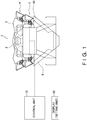
- FIG. 1 is a front view of a combination weighing apparatus 1 serving as a weighing apparatus pertaining to an embodiment of the invention.
- the combination weighing apparatus 1 weighs, with plural weigh hoppers 5, weights of product and combines the values of the weights that have been weighed by each of the weigh hoppers 5 so as to meet a predetermined total weight.
- the combination weighing apparatus 1 discharges downward the product with the predetermined total weight it has combined.
- product that is product to be weighed is conveyed above the combination weighing apparatus 1.
- the product is then placed on a dispersion feeder 2 and radially dispersed by vibration of the dispersion feeder 2.
- the product is sent to plural pool hoppers 4, which are circumferentially disposed via radial troughs 3 that come after the dispersion feeder 2. There the product is temporarily pooled, and thereafter the product is fed to the weigh hoppers 5 positioned under the pool hoppers 4.
- the weights of the product that has been fed to the weigh hoppers 5 are measured by load cells (weight detectors) provided for each of the weigh hoppers 5. Then, a combination of the weigh hoppers 5 from which the product is to be discharged to meet a weight or quantity in an allowable range is calculated on the basis of the measured weights of the product in each of the weigh hoppers 5. On the basis of that result, several of the weigh hoppers 5 discharge the product to a collection discharge chute 6.
- the pool hoppers 4 and the weigh hoppers 5 have substantially the same shape, so here they will be described using a weigh hopper 5 as an example.
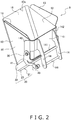
- FIG. 2 is a perspective view of the outward appearance of the weigh hopper 5.
- FIG. 3A is a side view of the weigh hopper 5 in a state in which a gate 20 is closed.
- FIG. 3B is a side view of the weigh hopper 5 in a state in which the gate 20 is open.
- the weigh hopper 5 includes a body 10, the gate 20, support shafts 30, and a lever 40.
- the body 10 is made of stainless steel.
- the body 10 is a square tube-shaped hollow member whose top and bottom are open. The four corners of the body 10 are rounded.
- the body 10 has a set of bilaterally symmetrical side walls 12 that oppose each other and two walls 11, 15 that are interposed between the two side walls 12.
- the wall that is positioned most outward of the two walls 11, 15 is a front wall 15, and the wall that opposes the front wall 15 is a back wall 11.
- the upper ends of the back wall 11, the two side walls 12, and the front wall 15 form an opening in the upper side of the body 10. This opening is an upper opening 10a.
- the lower ends of the back wall 11, the two side walls 12, and the front wall 15 form an opening in the lower side of the body 10. This opening is a lower opening 10b.
- the front wall 15 slopes downward toward the back wall 11, and the lower end of the front wall 15 is positioned in a lower position than the lower end of the back wall 11. Therefore, the open surface of the lower opening 10b slopes downward as seen from the lower end of the back wall 11.
- Guide plates 13 are attached to the upper ends of each of the side walls 12.
- the guide plates 13 slope upward and outward of the upper opening 10a from the upper ends of the side walls 12, so they can guide the product to be weighed into the body 10.
- a pair of brackets 14 are attached to the back wall 11.
- the pair of brackets 14 are slender plate-like plate metal members having flat surfaces parallel to the side walls 12.
- the pair of brackets 14 are attached in a cantilever fashion on the back wall 11.
- the free ends of each of the brackets 14 extend downward beyond the lower end of the back wall 11. That is, the free ends of each of the brackets 14 extend perpendicularly and downward from the back wall 11.
- the distance between the pair of brackets 14 is narrower than the distance between the pair of side walls 12, and the pair of brackets 14 are coupled to each other by two shafts 141 so that the distance between them can be maintained. Furthermore, couplings 142 having surfaces parallel to the back wall 11 are formed in the fixed ends of each of the brackets 14 by bending, and those surfaces are welded to, so as to be in close contact with, the back wall 11. The shafts 141 are caught on predetermined hooks (not shown in the drawings) of the combination weighing apparatus 1 of FIG. 1 .
- the gate 20 opens and closes the lower opening 10b in the body 10.
- the gate 20 includes a flat portion 21 and bent portions 22.
- the flat portion 21 is a plate having a sufficient enough area to be able to cover the lower opening 10b.
- the bent portions 22 are bent so as to rise up along the side walls 12.
- a lower end 23 of the flat portion 21 is bent backward. The bend is formed so that when the flat portion 21 closes off the lower opening 10b, the lower end 23 is in close contact with the distal end portion of the front wall 15.
- a reinforcement plate 41 is welded to the upper end of the gate 20.
- An upper end portion extending upward from the reinforcement plate 41 is supported, so as to be freely swingable, by the support shafts 30, and the lever 40 is integrally provided pointing downward from there.
- the support shafts 30 are shafts that hinge-couple the gate 20 to both side surfaces of the body 10.
- the support shafts 30 are close to the back wall 11, and when the gate 20 is opened from the lower opening 10b, a sufficient distance is formed between the upper end portion of the gate 20 and the back wall 11.
- the support shafts 30 are supported by bolts in the couplings 142.
- the lever 40 flips up the gate 20 in a counter-clockwise direction (looking straight at FIG. 3B ) about the support shafts 30.
- a roller 42 is attached, so as to be freely rotatable, to the distal end portion of the lever 40.
- the roller 42 meshes with an open/close lever 50 (see FIG. 1 ), the lever 40 is flipped up in the counter-clockwise direction (looking straight at FIG. 3B ), and the gate 20 opens and closes about the support shafts 30 in accompaniment therewith.
- the gate 20 is connected to a stepping motor 60 via the open/close lever 50.
- the stepping motor 60 is electrically connected to a control unit 70.
- the control unit 70 outputs a control signal to the stepping motor 60.
- the stepping motor 60 receives the control signal that is output from the control unit 70, it is driven to rotate on the basis of the control signal. Because of this rotation, the open/close lever 50 swings, the lever 40 is flipped up in the counter-clockwise direction (looking straight at FIG. 3B ), and the gate 20 opens and closes about the support shafts 30 in accompaniment therewith.
- the gate 20 shifts from a closed state to an open state as a result of a rotating shaft of the stepping motor 60 positively rotating from 0 degrees to 180 degrees.
- the gate 20 shifts from an open state to a closed state as a result of the rotating shaft of the stepping motor 60 negatively rotating from 180 degrees to 0 degrees.
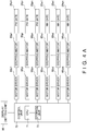
- FIG. 4A is a block diagram for describing electrical connections in the combination weighing apparatus 1 pertaining to the embodiment.
- the control unit 70 has a CPU 71 and a storage unit 73. Stepping motors 60p1 to 60pn that drive gates 20p1 to 20pn of the pool hoppers 4 and stepping motors 60w1 to 60wn that drive gates 20w1 to 20wn of the weigh hoppers 5 are electrically connected via motor drivers to the control unit 70.
- the control unit 70 controls the combination weighing apparatus 1 in accordance with a control program stored in the storage unit 73 on the basis of information that is input by the operator via a setting unit.
- control unit 70 outputs control signals to motor drivers 68p1 to 68pn to which the stepping motors 60p1 to 60pn are connected and motor drivers 68w1 to 68wn to which the stepping motors 60w1 to 60wn are connected.
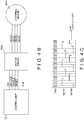
- FIG. 4B is a block diagram showing the state of connection between the control unit 70 and an arbitrary motor driver 68wi and stepping motor 60wi.
- FIG. 4C is a graph showing the relationship between a CLK (clock) signal that is input from the control unit 70 to the arbitrary motor driver 68wi and signals that are output from the motor driver 68wi to the stepping motor 60wi.
- control unit 70 is configured to be able to output a CLK (clock) signal, a CW/CCW signal (rotational direction switching signal), an ENABLE signal, a RESET signal, and Vref (reference voltage) to the motor driver 68wi.
- CLK clock
- CW/CCW rotational direction switching signal
- ENABLE ENABLE
- RESET RESET
- Vref reference voltage
- the motor driver 68wi is configured to be able to output a voltage value (OUTA+, OUTA-, OUTB+, OUTB-) corresponding to a desired current value (a set current lout) to the stepping motor 60wi.
- the set current lout of the stepping motor 60wi is determined by the voltage set for Vref (reference voltage).
- the waveforms of OUTA+ and OUTB+ shown in FIG. 4C represent the case of 1-2 phase excitation.
- the speed of the stepping motor 60wi is determined by the timing of the rising edge of the CLK (clock) signal.
- the control unit 70 sets Vref (reference voltage) so that voltage values corresponding to current values that each stepping motor needs are output from the motor drivers 68p1 to 68pn and the motor drivers 68w1 to 68wn.
- predetermined voltage values are intermittently applied as pulse trains to the stepping motors 60p1 to 60pn and the stepping motors 60w1 to 60wn, and the current values flowing in the stepping motors 60p1 to 60pn and the stepping motors 60w1 to 60wn are controlled.
- the pulse voltages are applied to the stepping motors 60p1 to 60pn and the stepping motors 60w1 to 60wn while their pulse widths are temporally changed.
- the values that the control unit 70 controls are current values, but it is voltage values that are output to the stepping motors 60p1 to 60pn and the stepping motors 60w1 to 60wn.
- the method of outputting the voltage values to the stepping motors 60p1 to 60pn and the stepping motors 60w1 to 60wn is not limited to a method where fixed voltage values such as described above are intermittently output as pulse trains, and may also be a method where the voltage values that are output to the stepping motors 60p1 to 60pn and the stepping motors 60w1 to 60wn are temporally varied.
- the gate 20 is set to reach a completely open state when the rotating shaft of the stepping motor 60 has rotated 180 degrees. Consequently, operations where the angle of rotation of the rotating shaft of the stepping motor 60 progresses from 0 degrees to 180 degrees and thereafter returns from 180 degrees to 0 degrees will comprise one cycle.
- control unit 70 one cycle is divided into a first interval to an Nth interval, and the control signal that is input to the stepping motor 60 per each of the intervals is set so that speeds that have been set per each of the intervals can be achieved.
- the control signal that is input to the stepping motor 60 is the voltage value corresponding to the desired current value.
- FIG. 5 is a table showing the setting status of speeds of the stepping motor 60.
- This display is stored in the storage unit of the control unit 70 and can be displayed on a display 80 electrically connected to the control unit 70. It will be noted that input can be made to the control unit 70 via the display 80, and the display 80 also has a function as a setting unit.
- a "+" sign added before numerical values of speeds means that the stepping motor 60 is rotating in the direction in which it opens the gate and a "-" sign means that the stepping motor 60 is rotating in the direction in which it closes the gate.
- section number, interval, speed, hold time, slow start, and slow stop columns are provided sequentially from the left side of the table.
- the section numbers increase or decrease as needed.
- the intervals are displayed as percentages (%) in which 180 degrees is 100%.
- the speeds are the rotational speeds of the rotating shaft of the stepping motor 60 in each interval.
- section 1 is an interval from 0 to 80% of 0 to 180 degrees, that is, an interval in which the angle of rotation goes from 0 to 144 degrees, and the set speed in this interval is +140 r/m.
- section 2 which comes after section 1, is an interval from 80 to 100%, that is, an interval in which the angle of rotation goes from 144 to 180 degrees, and the set speed in this interval is +100 r/m.
- section 3 which comes after section 2, is an interval from 100 to 50%, that is, an interval in which the angle of rotation goes from 180 to 90 degrees, and the set speed in this interval is -140 r/m.
- section 4 which comes after section 3, is an interval from 50 to 30%, that is, an interval in which the angle of rotation goes from 90 to 54 degrees, and the set speed in this interval is -105 r/m.
- section 5 which comes after section 4, is an interval from 30 to 10%, that is, an interval in which the angle of rotation goes from 54 to 18 degrees, and the set speed in this interval is -100 r/m.
- section 6 which comes after section 5, is an interval from 10 to 0%, that is, an interval in which the angle of rotation goes from 18 to 0 degrees, and the set speed in this interval is -190 r/m.
- the current value that is input to the stepping motor 60 is set per each of the intervals, and normally a default current value is applied.
- the operator can, by touching a "Set Motor Drive Current Pattern" touch button 801 located at the bottom of the table ( FIG. 5 ) displayed on the display 80, switch the display of the display 80 to the table shown in FIG. 6B (a table showing the setting status of the current values per interval) and check the current values per interval.
- FIG. 6A is a table showing "Current Levels due to Mechanical Factors” and “Current Levels due to Mechanical Factors + Acceleration Factors” relative to the angle of rotation in one cycle of the stepping motor 60. Furthermore, FIG. 6B is a table showing the setting status of the current values per interval of the angle of rotation.
- a "+" sign added before numerical values of speeds means that the stepping motor 60 is rotating in the direction in which it opens the gate and a "-" sign means that the stepping motor 60 is rotating in the direction in which it closes the gate.
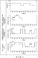
- FIG. 7 is a chart in which a graph showing "Speed” versus the angle of rotation, a graph showing "Current A due to Mechanical Factors” versus the angle of rotation, a graph showing “Current B due to Acceleration Factors” versus the angle of rotation, and a graph showing "Set Current” versus the angle of rotation in one cycle of the stepping motor 60 are arranged sequentially from the top and collectively displayed in order to supplement FIG. 6A and FIG. 6B .
- the graph showing "Speed" versus the angle of rotation in the uppermost row of FIG. 7 is a schematization of the set speeds per interval shown in FIG. 5 .
- the four rows in FIG. 7 will be called the uppermost row, the second row, the third row, and the fourth row.
- the horizontal axes of the graphs in the second row, the third row, and the fourth row in FIG. 7 represent the angle to which the stepping motor 60 has rotated.
- graduations are given in 30-degree spacings, but this is not intended to represent the intervals.
- the vertical axes of the graphs in the second row, the third row, and the fourth row in FIG. 7 represent the current level.
- the current level can be set to any of three levels, "0", “+1", and "+2", starting from low.
- current level "0” does not mean that the current value is 0 amps; rather, it is a value representing the level of the current value. In other words, current level "0" is a predetermined current value serving as a standard.
- the gate 20 is energized in the closed direction by a spring (not shown in the drawings), so when the rotating shaft of the stepping motor 60 drives the gate 20 in the open direction, the current value increases because the load of the spring acts on the gate 20.
- the left column of FIG. 6B shows default current values per interval.
- the right column of FIG. 6B shows the setting status of the current values per interval after a change in settings.
- the graph in the second row of FIG. 7 which shows "Current A needed due to Mechanical Factors" relative to the angle of rotation, is a graph of the current values per interval listed in the left column of FIG. 6B , and each current value is a default value.
- section 1 is an interval from 0 to 15% of the angle of rotation of 0 to 180 degrees, that is, an interval in which the angle of rotation goes from 0 to 27 degrees, and the current value in this interval is set to eco1.
- the current value settings comprise three level settings of eco1, half, and full (in the current levels of FIG. 7 , three level settings of "0", “+1", and "+2"), and have a magnitude correlation of eco1 ⁇ half ⁇ full.
- section 2 is an interval from 15 to 35%, that is, an interval in which the angle of rotation goes from 27 to 63 degrees, and the current value in this interval is set to half.
- section 3 is an interval from 35 to 65%, that is, an interval in which the angle of rotation goes from 63 to 117 degrees, and the current value in this interval is set to full.
- section 4 is an interval from 65 to 85%, that is, an interval in which the angle of rotation goes from 117 to 153 degrees, and the current value in this interval is set to half.
- section 5 is an interval from 85 to 100%, that is, an interval in which the angle of rotation goes from 153 to 180 degrees, and the current value in this interval is set to eco1.
- section 6 is an interval from 100 to 0%, that is, an interval in which the angle of rotation goes from 180 to 0 degrees, and the current value in this interval is set to eco1. It will be noted that the interval in which the angle of rotation goes from 180 to 0 degrees is an interval in which the gate 20 returns to the closed state from the open state and can utilize the energizing force of the spring, so the current due to mechanical factors is low and stable.
- the current values per interval of the stepping motor 60 are initially set assuming current A due to mechanical factors as shown in the left column of FIG. 6B and the second row of FIG. 7 .
- the graph in the third row of FIG. 7 is a graph representing "Current B needed due to Acceleration Factors" relative to the angle of rotation.
- the interval from 0 to 11% that is, the interval in which the angle of rotation goes from 0 to 20 degrees
- the stepping motor 60 starts up in order for the gate 20 to start operating from the closed state to the open state, so current for acceleration becomes necessary. Consequently, the current value is set to full.
- the interval from 75 to 86% is a deceleration interval for the gate 20 to reliably stop in the completely open position, and current for braking becomes necessary. Consequently, the current value is set to full.
- the interval from 94 to 100% that is, the interval in which the angle of rotation goes from 170 to 180 degrees, is an interval in which the gate 20 becomes completely stopped, and current for braking becomes necessary. Consequently, the current value is set to full.
- the interval from 100 to 92% is an interval in which the stepping motor 60 starts up in order for the gate 20 to start operating from the open state to the closed state, so current for acceleration becomes necessary. Consequently, the current value is set to full.
- the interval from 56 to 42% that is, the interval in which the angle of rotation goes from 100 to 75 degrees
- the interval from 56 to 42% is an interval in which the gate 20 is decelerated, and current for braking becomes necessary. Consequently, the current value is set to half.
- the interval from 17 to 0% that is, the interval in which the angle of rotation goes from 30 to 0 degrees, is an interval in which the gate 20 becomes completely stopped, and current for braking becomes necessary. Consequently, the current value is set to full.
- the operating time of the stepping motor 60 in each interval includes the time from when the control unit increases or decreases Vref (reference voltage) to set the current level to until the current level actually reaches the set value and the time from when the stepping motor 60 starts accelerating or decelerating to until it finishes accelerating or decelerating.
- Vref reference voltage
- the right column in FIG 6B follows the graph in the fourth row of FIG. 7 and shows results of having set the intervals and changed the settings of the current values per each of the intervals.
- section 1 is an interval from 0 to 11% of the angle of rotation of 0 to 180 degrees, that is, an interval in which the angle of rotation goes from 0 to 20 degrees, and the current value in this interval is set to full.
- section 2 is an interval from 11 to 17%, that is, an interval in which the angle of rotation goes from 20 to 30 degrees, and the current value in this interval is set to eco1.
- section 3 is an interval from 17 to 33%, that is, an interval in which the angle of rotation goes from 30 to 60 degrees, and the current value in this interval is set to half.
- section 4 is an interval from 33 to 67%, that is, an interval in which the angle of rotation goes from 60 to 120 degrees, and the current value in this interval is set to full.
- section 5 is an interval from 67 to 75%, that is, an interval in which the angle of rotation goes from 120 to 135 degrees, and the current value in this interval is set to half.
- section 6 is an interval from 75 to 86%, that is, an interval in which the angle of rotation goes from 135 to 155 degrees, and the current value in this interval is set to full.
- section 7 is an interval from 86 to 89%, that is, an interval in which the angle of rotation goes from 155 to 160 degrees, and the current value in this interval is set to half.
- section 8 is an interval from 89 to 94%, that is, an interval in which the angle of rotation goes from 160 to 170 degrees, and the current value in this interval is set to eco1.
- section 9 is an interval from 94 to 100%, that is, an interval in which the angle of rotation goes from 170 to 180 degrees, and the current value in this interval is set to full.
- section 10 is an interval from 100 to 92%, that is, an interval in which the angle of rotation goes from 180 to 165 degrees, and the current value in this interval is set to full.
- section 11 is an interval from 92 to 56%, that is, an interval in which the angle of rotation goes from 165 to 100 degrees, and the current value in this interval is set to eco1.
- section 12 is an interval from 56 to 42%, that is, an interval in which the angle of rotation goes from 100 to 75 degrees, and the current value in this interval is set to half.
- section 13 is an interval from 42 to 17%, that is, an interval in which the angle of rotation goes from 75 to 30 degrees, and the current value in this interval is set to eco1.
- section 14 is an interval from 17 to 0%, that is, an interval in which the angle of rotation goes from 30 to 0 degrees, and the current value in this interval is set to full.
- the operator can, via the display 80 serving as a setting unit, set the angles of rotation (intervals) and speeds of the stepping motor 60, set the angles of rotation (intervals) and current values of the stepping motor 60, and change the current values on the basis of changes in speed (acceleration).
- the control signal that is input to the stepping motor 60 that is, the current value that is input to the stepping motor 60, is changed in conjunction therewith.
- the current values per interval are changed in conjunction therewith from the default current values (see the left column of FIG. 6B ) to appropriate values (see the right column of FIG. 6B and the fourth row in FIG. 7 ).
- the control unit 70 controls the stepping motor 60 via the control signal that is input to the stepping motor 60.
- the control signal that is input to the stepping motor 60 is a voltage value corresponding to a desired current value.
- the control unit changes the control signal to the stepping motor 60 in conjunction with a change in the settings of the opening and closing speed of the gate 20. As a result, it becomes possible to supply power needed for the operation of the gate 20, and power can be saved.
- the combination weighing apparatus 1 includes the display 80 that functions as a setting unit that sets or changes the opening and closing speed of the gate 20, so it becomes possible to reset the opening and closing speed of the gate in a case where the (default) opening and closing speed is unsuitable.
- the necessary power becomes clear as a result of an optimum opening and closing speed being set, and wasteful supply of power can be avoided so that power can be saved.
- the period in which the gate 20 goes from a closed state to an open state is divided into plural intervals. Furthermore, the opening and closing speed of the gate is set per each of the intervals. As a result, opening and closing speeds suited to the state of the gate 20 in those intervals can be set. The necessary power becomes clear as a result of optimum opening and closing speeds being set, and wasteful supply of power can be avoided so that power can be saved.
- the control signal to the stepping motor 60 is set per each of the opening and closing speeds of the gate 20. There is a control signal corresponding to each of the opening and closing speeds, so when an opening and closing speed is changed, the control signal changes to the control signal corresponding to the opening and closing speed that has been changed, so the opening and closing speed is automatically controlled.
- the combination weighing apparatus 1 when the opening and closing speed of the gate 20 has been changed in any interval of the plural intervals, only the control signal corresponding to the interval in which the opening and closing speed of the gate 20 was changed is changed. As a result, for example, in a case where there is an interval in which power is being wastefully consumed, it suffices to simply change the set value of the opening and closing speed of the gate 20 in that interval.
- control unit 70 calculates the control signal that accords with the opening and closing speeds of the gate 20. It will be noted regarding the signal value of the control signal that values found by calculation per each of the opening and closing speeds beforehand may also be tabulated.
- the control unit 70 raises Vref (reference voltage) to increase the voltage level of the control signal in order to increase the current of the stepping motor 60 in a case where the opening and closing speed of the gate 20 has become faster than the opening and closing speed that was utilized when generating the control signal that was initially set. Furthermore, the control unit 70 lowers Vref (reference voltage) to decrease the voltage level of the control signal in order to reduce the current of the stepping motor 60 in a case where the opening and closing speed of the gate has become slower than the opening and closing speed that was utilized when generating the control signal that was initially set.
- Vref reference voltage
- the display could be switched from the table in FIG. 5 showing the setting status of the speeds of the stepping motor 60 to the motor drive current pattern setting table appearing in the left column or the right column of the table in FIG. 6B .
- FIG. 8 is a table showing the setting status of current values per interval at an initial setting stage.
- section number, interval, speed, hold time, slow start, slow stop, and power setting columns are provided sequentially from the left of the table.
- the section numbers increase or decrease in correspondence to the number of intervals.
- the intervals are displayed as percentages (%) in which 180 degrees is 100%.
- the speeds are the rotational speeds of the rotating shaft of the stepping motor 60 in each interval.
- the operator can set or change the current values in the power setting column while looking at the intervals and the speeds in those intervals.
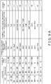
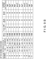
- FIG. 9A is a table showing "Current Levels due to Mechanical Factors” and “Current Levels due to Mechanical Factors + Acceleration Factors” relative to the angle of rotation in one cycle of the stepping motor 60. Furthermore, FIG. 9B is a table showing the setting status of current values per interval after a change in the settings of the opening and closing speeds.
- a "+" sign added before numerical values of speeds means that the stepping motor 60 is rotating in the direction in which it opens the gate and a "-" sign means that the stepping motor 60 is rotating in the direction in which it closes the gate.
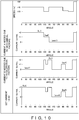
- FIG. 10 is a chart in which a graph showing "Speed” versus the angle of rotation, a graph showing "Current A due to Mechanical Factors” versus the angle of rotation, a graph showing “Current B due to Acceleration Factors” versus the angle of rotation, and a graph showing "Set Current” versus the angle of rotation in one cycle of the stepping motor 60 are arranged sequentially from the top and collectively displayed in order to supplement FIG. 9A and FIG. 9B .
- the four rows in FIG. 10 will be called the uppermost row, the second row, the third row, and the fourth row.
- the graph in the second row of FIG. 10 which shows "Current A needed due to Mechanical Factors" relative to the angle of rotation, is a graph of the current values per interval in FIG. 8 , and each current value is a default value.
- section 1 is an interval from 0 to 80% of the angle of rotation of 0 to 180 degrees, that is, an interval in which the angle of rotation goes from 0 to 144 degrees, and the current value in this interval is set to full.
- the current value settings comprise three level settings of eco1, half, and full (in the current levels of FIG. 10 , three level settings of "0", “+1", and “+2"), and have a magnitude correlation of eco1 ⁇ half ⁇ full.
- section 2 is an interval from 80 to 100%, that is, an interval in which the angle of rotation goes from 144 to 180 degrees, and the current value in this interval is set to half.
- sections 3, 4, and 5 are intervals from 100 to 10%, that is, intervals in which the angle of rotation goes from 180 to 18 degrees, and the current value in these intervals is set to eco1.
- section 6 is an interval from 18 to 0%, that is, an interval in which the angle of rotation goes from 18 to 0 degrees, and the current value in this interval is set to full.
- the graph in the third row of FIG. 10 is a graph representing "Current B needed due to Acceleration Factors" relative to the angle of rotation.
- the interval from 80 to 86% that is, the interval in which the angle of rotation goes from 144 to 155 degrees
- the interval from 86 to 94% that is, the interval in which the angle of rotation goes from 155 to 170 degrees, mitigates the braking of the gate 20. Consequently, the current value is set to half.
- the interval from 94 to 100% that is, the interval in which the angle of rotation goes from 170 to 180 degrees, is an interval in which the gate 20 becomes completely stopped, and current for braking becomes necessary. Consequently, the current value is set to full.
- the interval from 100 to 91% is an interval in which the stepping motor 60 starts up in order for the gate 20 to start operating from the open state to the closed state, so current for acceleration becomes necessary. Consequently, the current value is set to full.
- the interval from 56 to 42% that is, the interval in which the angle of rotation goes from 100 to 75 degrees
- the interval from 56 to 42% is an interval in which the gate 20 is decelerated, and current for braking becomes necessary. Consequently, the current value should be set to half.
- the interval from 17 to 0% that is, the interval in which the angle of rotation goes from 30 to 0 degrees, is an interval in which the gate 20 becomes completely stopped, and current for braking becomes necessary. Consequently, the current value should be set to full.
- FIG. 9B follows the graph in the fourth row of FIG. 10 and shows results of having set the intervals and changed the settings of the current values per each of the intervals.
- section 1 is an interval from 0 to 80% of the angle of rotation of 0 to 180 degrees, that is, an interval in which the angle of rotation goes from 0 to 144 degrees, and the current value in this interval is set to full.
- section 2 is an interval from 80 to 86%, that is, an interval in which the angle of rotation goes from 144 to 170 degrees, and the current value in this interval is set to half.
- section 3 is an interval from 86 to 100%, that is, an interval in which the angle of rotation goes from 170 to 180 degrees, and the current value in this interval is set to full.
- section 4 is an interval from 100 to 91%, that is, an interval in which the angle of rotation goes from 180 to 165 degrees, and the current value in this interval is set to full.
- section 5 is an interval from 91 to 56%, that is, an interval in which the angle of rotation goes from 165 to 100 degrees, and the current value in this interval is set to eco1.
- section 6 is an interval from 56 to 50%, that is, an interval in which the angle of rotation goes from 100 to 90 degrees, and the current value in this interval is set to half.
- section 7 is an interval from 50 to 42%, that is, an interval in which the angle of rotation goes from 90 to 75 degrees, and the current value in this interval is set to half.
- section 8 is an interval from 42 to 30%, that is, an interval in which the angle of rotation goes from 75 to 54 degrees, and the current value in this interval is set to eco1.
- section 9 is an interval from 30 to 17%, that is, an interval in which the angle of rotation goes from 54 to 30 degrees, and the current value in this interval is set to eco1.
- section 10 is an interval from 17 to 11%, that is, an interval in which the angle of rotation goes from 30 to 20 degrees, and the current value in this interval is set to full.
- section 11 is an interval from 11 to 0%, that is, an interval in which the angle of rotation goes from 20 to 0 degrees, and the current value in this interval is set to full.
- the opening and closing speed of the gate 20 is set or has its setting changed in conjunction therewith.
- the operating time of the stepping motor 60 in each interval includes the time from when the control unit increases or decreases Vref (reference voltage) to set the current level to until the current level actually reaches the set value and the time from when the stepping motor 60 starts accelerating or decelerating to until it finishes accelerating or decelerating.
- Vref reference voltage
- the operator can, via the display 80 serving as a setting unit, set the angles of rotation (intervals), speeds, and current values of the stepping motor 60 and change the current values on the basis of changes in the speed (acceleration) of the stepping motor 60.
- the control signal that is input to the stepping motor 60 that is, the current value that is input to the stepping motor 60, is changed in conjunction therewith.
- the current values per interval are changed in conjunction therewith from the default current values ( FIG. 8 ) to appropriate values (see FIG. 9B and the fourth row in FIG. 10 ).
- the example modification includes all the characteristics of the embodiment.
- the setting status of the speeds of the stepping motor 60 and the motor drive current pattern setting table are collectively displayed, so the operator can, while looking at the setting status of the speeds of the stepping motor 60, set the angles of rotation (intervals), speeds, and current values of the stepping motor 60 and change the settings of the current values on the basis of a change in the speed (acceleration) of the stepping motor 60.
- control unit 70 may also calculate the control signal that accords with the opening and closing speeds of the gate 20. Moreover, regarding the signal value of the control signal, values found by calculation per each of the opening and closing speeds beforehand may also be tabulated.
- control unit 70 can raise Vref (reference voltage) to increase the voltage level of the control signal in order to increase the current of the stepping motor 60 in a case where the opening and closing speed of the gate 20 has become faster than the opening and closing speed that was utilized when generating the control signal that was initially set. Furthermore, the control unit 70 can lower Vref (reference voltage) to decrease the voltage level of the control signal in order to reduce the current of the stepping motor 60 in a case where the opening and closing speed of the gate has become slower than the opening and closing speed that was utilized when generating the control signal that was initially set.
- Vref reference voltage
- Patent Document 1 JP-ANo. 2013-167594
Landscapes
- Physics & Mathematics (AREA)
- General Physics & Mathematics (AREA)
- Engineering & Computer Science (AREA)
- Power Engineering (AREA)
- Control Of Stepping Motors (AREA)
Abstract
Description
- The present invention relates to a weighing apparatus, and particularly relates to a combination weighing apparatus that feeds product to be weighed to plural product bins, weighs the product in each of the product bins, and selects a combination of product bins whose combined product meets a target combined mass.
- In recent years, combination weighing apparatuses configured to feed product to be weighed to plural product bins called hoppers, weigh the product in each of the product bins, select a combination of product bins whose combined product meets a target combined mass, and involve them in that combination have become widespread. For example, patent document 1 (
JP-ANo. 2013-167594 drive currents 0 ≤ I1 < 12 < 13 for current applied to a drive unit of a hopper gate and which, by using drive current I1 when holding the hopper gate in a closed state, using drive current 12 when holding the hopper gate in an open state, and using drive current 13 when driving the hopper gate, reduces power consumption in the drive unit of the hopper gate. - However, in the above weighing apparatus, the drive current that drives the hopper gate to open and close is controlled to a fixed value despite the fact that the necessary torque changes depending on the open/closed position of the hopper gate, and the maximum value of drive current needed to cause the hopper gate to operate is employed. Therefore, during the opening and closing operations of the hopper gate, the maximum drive current always continues to be supplied, leading to wasteful power consumption.
- It is a problem of the present invention to provide a combination weighing apparatus that reduces power consumption during opening and closing operations of a hopper gate.
- A weighing apparatus pertaining to a first aspect of the invention includes a hopper, a drive unit, and a control unit. The hopper has an opening and closing gate and, by opening and closing the gate, temporarily retains and thereafter discharges product that has been fed thereto from outside. The drive unit causes the gate to open and close. The control unit controls the drive unit via a control signal. The control unit changes the control signal to the drive unit in conjunction with a change in the setting of the opening and closing speed of the gate.
- In this weighing apparatus, the power needed by the drive unit during the series of operations in which the gate shifts from the closed state to the open state changes in accordance with the operations of the gate, such as "startup," the "opening operation of the gate," the "stopping of the gate in the open position," the "anchoring of the gate in the open position," "startup," the "closing operation of the gate," and the "stopping of the gate in the closed position." If the power supplied to the drive unit were fixed to match its value when the drive unit requires the most power, stable operations of the gate are easily obtained, but this leads to wasteful power consumption. Thus, by changing the control signal to the drive unit in conjunction with a change in the setting of the opening and closing speed of the gate, it becomes possible to supply power needed for the operation of the gate, and power can be saved.
- A weighing apparatus pertaining to a second aspect of the invention is the weighing apparatus pertaining to the first aspect, further including a setting unit that sets or changes the opening and closing speed of the gate.
- In this weighing apparatus, by providing the setting unit, it becomes possible to reset the opening and closing speed of the gate in a case where the (default) opening and closing speed is unsuitable. The necessary power becomes clear as a result of an optimum opening and closing speed being set, and wasteful supply of power can be avoided so that power can be saved.
- A weighing apparatus pertaining to a third aspect of the invention is the weighing apparatus pertaining to the first aspect or the second aspect, wherein a period in which the gate shifts from a closed state to an open state is divided into plural intervals. The opening and closing speed of the gate is set per each of the intervals.
- In this weighing apparatus, the period in which the gate shifts from the closed state to the open state is divided into plural intervals, so opening and closing speeds suited to the state of the gate in those intervals can be set. The necessary power becomes clear as a result of optimum opening and closing speeds being set, and wasteful supply of power can be avoided so that power can be saved.
- A weighing apparatus pertaining to a fourth aspect of the invention is the weighing apparatus pertaining to the third aspect, wherein the control signal is set per each of the opening and closing speeds of the gate.
- In this weighing apparatus, there is a control signal corresponding to each of the opening and closing speeds, so when an opening and closing speed is changed, the control signal changes to the control signal corresponding to the opening and closing speed that has been changed, so the opening and closing speed is automatically controlled.
- A weighing apparatus pertaining to a fifth aspect of the invention is the weighing apparatus pertaining to the fourth aspect, wherein when the opening and closing speed of the gate has been changed in any interval of the plural intervals, only the control signal corresponding to the interval in which the opening and closing speed of the gate was changed is changed.
- In this weighing apparatus, in a case where, for example, there is an interval in which power is being wastefully consumed, it suffices to simply change the set value of the opening and closing speed of the gate in that interval.
- A weighing apparatus pertaining to a sixth aspect of the invention is the weighing apparatus pertaining to the fourth aspect, wherein the control unit calculates the control signal that accords with the opening and closing speed of the gate.
- It will be noted regarding the signal value of the control signal that values found by calculation per opening and closing speed beforehand may also be tabulated.
- A weighing apparatus pertaining to a seventh aspect of the invention is the weighing apparatus pertaining to the first aspect or the second aspect, wherein the control unit increases the control signal in a case where the opening and closing speed of the gate has become faster than the opening and closing speed that was utilized when generating the control signal that was initially set. Furthermore, the control unit decreases the control signal in a case where the opening and closing speed of the gate has become slower than the opening and closing speed that was utilized when generating the control signal that was initially set.
- The weighing apparatus pertaining to the invention changes the control signal to the drive unit in conjunction with a change in the setting of the opening and closing speed of the gate, whereby it becomes possible to supply power needed for the operation of the gate, and power can be saved.
-
-
FIG. 1 is a front view of a combination weighing apparatus serving as a weighing apparatus pertaining to an embodiment of the invention; -
FIG. 2 is a perspective view of the outward appearance of a weigh hopper; -
FIG. 3A is a side view of the weigh hopper in a state in which a gate is closed; -
FIG. 3B is a side view of the weigh hopper in a state in which the gate is open; -
FIG. 4A is a block diagram for describing electrical connections in the combination weighing apparatus pertaining to the embodiment; -
FIG. 4B is a block diagram showing the state of connection between a control unit, a motor driver, and a stepping motor; -
FIG. 4C is a graph showing the relationship between a CLK (clock) signal that is input from the control unit to the motor driver and signals that are output from the motor driver to the stepping motor; -
FIG. 5 is a table showing the setting status of speeds of the stepping motor; -
FIG. 6A is a table showing "Current Levels due to Mechanical Factors" and "Current Levels due to Mechanical Factors + Acceleration Factors" relative to the angle of rotation in one cycle of the stepping motor; -
FIG. 6B is a table showing the setting status of current values per interval; -
FIG. 7 is a chart in which a graph showing "Speed" versus the angle of rotation, a graph showing "Current A due to Mechanical Factors" versus the angle of rotation, a graph showing "Current B due to Acceleration Factors" versus the angle of rotation, and a graph showing "Set Current" versus the angle of rotation in one cycle of the stepping motor are arranged sequentially from the top and collectively displayed; -
FIG. 8 is a table showing the setting status of current values per interval at an initial setting stage; -
FIG. 9A is a table showing "Current Levels due to Mechanical Factors" and "Current Levels due to Mechanical Factors + Acceleration Factors" relative to the angle of rotation in one cycle of the stepping motor; -
FIG. 9B is a table showing the setting status of current values per interval after a change in settings; and -
FIG. 10 is a chart in which a graph showing "Speed" versus the angle of rotation, a graph showing "Current A due to Mechanical Factors" versus the angle of rotation, a graph showing "Current B due to Acceleration Factors" versus the angle of rotation, and a graph showing "Set Current" versus the angle of rotation in one cycle of the stepping motor are arranged sequentially from the top and collectively displayed. - An embodiment of the invention will be described with reference to the drawings. The embodiment described below is a specific example of the invention and is not intended to limit the technical scope of the invention.
-
FIG. 1 is a front view of acombination weighing apparatus 1 serving as a weighing apparatus pertaining to an embodiment of the invention. Referring toFIG. 1 , thecombination weighing apparatus 1 weighs, withplural weigh hoppers 5, weights of product and combines the values of the weights that have been weighed by each of theweigh hoppers 5 so as to meet a predetermined total weight. Thecombination weighing apparatus 1 discharges downward the product with the predetermined total weight it has combined. - Specifically, product that is product to be weighed is conveyed above the
combination weighing apparatus 1. The product is then placed on adispersion feeder 2 and radially dispersed by vibration of thedispersion feeder 2. - The product is sent to
plural pool hoppers 4, which are circumferentially disposed viaradial troughs 3 that come after thedispersion feeder 2. There the product is temporarily pooled, and thereafter the product is fed to theweigh hoppers 5 positioned under thepool hoppers 4. - The weights of the product that has been fed to the
weigh hoppers 5 are measured by load cells (weight detectors) provided for each of theweigh hoppers 5. Then, a combination of theweigh hoppers 5 from which the product is to be discharged to meet a weight or quantity in an allowable range is calculated on the basis of the measured weights of the product in each of theweigh hoppers 5. On the basis of that result, several of theweigh hoppers 5 discharge the product to acollection discharge chute 6. - As shown in
FIG. 1 , thepool hoppers 4 and theweigh hoppers 5 have substantially the same shape, so here they will be described using aweigh hopper 5 as an example. -
FIG. 2 is a perspective view of the outward appearance of theweigh hopper 5.FIG. 3A is a side view of theweigh hopper 5 in a state in which agate 20 is closed.FIG. 3B is a side view of theweigh hopper 5 in a state in which thegate 20 is open. - Referring to
FIG. 2 ,FIG. 3A , andFIG. 3B , theweigh hopper 5 includes abody 10, thegate 20,support shafts 30, and alever 40. - The
body 10 is made of stainless steel. Thebody 10 is a square tube-shaped hollow member whose top and bottom are open. The four corners of thebody 10 are rounded. Thebody 10 has a set of bilaterallysymmetrical side walls 12 that oppose each other and twowalls side walls 12. - The wall that is positioned most outward of the two
walls front wall 15, and the wall that opposes thefront wall 15 is aback wall 11. The upper ends of theback wall 11, the twoside walls 12, and thefront wall 15 form an opening in the upper side of thebody 10. This opening is anupper opening 10a. - The lower ends of the
back wall 11, the twoside walls 12, and thefront wall 15 form an opening in the lower side of thebody 10. This opening is alower opening 10b. - The
front wall 15 slopes downward toward theback wall 11, and the lower end of thefront wall 15 is positioned in a lower position than the lower end of theback wall 11. Therefore, the open surface of thelower opening 10b slopes downward as seen from the lower end of theback wall 11. -
Guide plates 13 are attached to the upper ends of each of theside walls 12. Theguide plates 13 slope upward and outward of theupper opening 10a from the upper ends of theside walls 12, so they can guide the product to be weighed into thebody 10. - A pair of
brackets 14 are attached to theback wall 11. The pair ofbrackets 14 are slender plate-like plate metal members having flat surfaces parallel to theside walls 12. The pair ofbrackets 14 are attached in a cantilever fashion on theback wall 11. The free ends of each of thebrackets 14 extend downward beyond the lower end of theback wall 11. That is, the free ends of each of thebrackets 14 extend perpendicularly and downward from theback wall 11. - The distance between the pair of
brackets 14 is narrower than the distance between the pair ofside walls 12, and the pair ofbrackets 14 are coupled to each other by twoshafts 141 so that the distance between them can be maintained. Furthermore,couplings 142 having surfaces parallel to theback wall 11 are formed in the fixed ends of each of thebrackets 14 by bending, and those surfaces are welded to, so as to be in close contact with, theback wall 11. Theshafts 141 are caught on predetermined hooks (not shown in the drawings) of thecombination weighing apparatus 1 ofFIG. 1 . - The
gate 20 opens and closes thelower opening 10b in thebody 10. Thegate 20 includes aflat portion 21 andbent portions 22. Theflat portion 21 is a plate having a sufficient enough area to be able to cover thelower opening 10b. Thebent portions 22 are bent so as to rise up along theside walls 12. - A
lower end 23 of theflat portion 21 is bent backward. The bend is formed so that when theflat portion 21 closes off thelower opening 10b, thelower end 23 is in close contact with the distal end portion of thefront wall 15. - A
reinforcement plate 41 is welded to the upper end of thegate 20. An upper end portion extending upward from thereinforcement plate 41 is supported, so as to be freely swingable, by thesupport shafts 30, and thelever 40 is integrally provided pointing downward from there. - The
support shafts 30 are shafts that hinge-couple thegate 20 to both side surfaces of thebody 10. Thesupport shafts 30 are close to theback wall 11, and when thegate 20 is opened from thelower opening 10b, a sufficient distance is formed between the upper end portion of thegate 20 and theback wall 11. Thesupport shafts 30 are supported by bolts in thecouplings 142. - The
lever 40 flips up thegate 20 in a counter-clockwise direction (looking straight atFIG. 3B ) about thesupport shafts 30. Aroller 42 is attached, so as to be freely rotatable, to the distal end portion of thelever 40. Theroller 42 meshes with an open/close lever 50 (seeFIG. 1 ), thelever 40 is flipped up in the counter-clockwise direction (looking straight atFIG. 3B ), and thegate 20 opens and closes about thesupport shafts 30 in accompaniment therewith. - Here, the
gate 20 is connected to a steppingmotor 60 via the open/close lever 50. The steppingmotor 60 is electrically connected to acontrol unit 70. Thecontrol unit 70 outputs a control signal to the steppingmotor 60. When the steppingmotor 60 receives the control signal that is output from thecontrol unit 70, it is driven to rotate on the basis of the control signal. Because of this rotation, the open/close lever 50 swings, thelever 40 is flipped up in the counter-clockwise direction (looking straight atFIG. 3B ), and thegate 20 opens and closes about thesupport shafts 30 in accompaniment therewith. - Specifically, the
gate 20 shifts from a closed state to an open state as a result of a rotating shaft of the steppingmotor 60 positively rotating from 0 degrees to 180 degrees. Thegate 20 shifts from an open state to a closed state as a result of the rotating shaft of the steppingmotor 60 negatively rotating from 180 degrees to 0 degrees. -
FIG. 4A is a block diagram for describing electrical connections in thecombination weighing apparatus 1 pertaining to the embodiment. - Referring to
FIG. 4A , thecontrol unit 70 has aCPU 71 and astorage unit 73. Stepping motors 60p1 to 60pn that drive gates 20p1 to 20pn of thepool hoppers 4 and stepping motors 60w1 to 60wn that drive gates 20w1 to 20wn of theweigh hoppers 5 are electrically connected via motor drivers to thecontrol unit 70. - The
control unit 70 controls thecombination weighing apparatus 1 in accordance with a control program stored in thestorage unit 73 on the basis of information that is input by the operator via a setting unit. - Specifically, the
control unit 70 outputs control signals to motor drivers 68p1 to 68pn to which the stepping motors 60p1 to 60pn are connected and motor drivers 68w1 to 68wn to which the stepping motors 60w1 to 60wn are connected. -
FIG. 4B is a block diagram showing the state of connection between thecontrol unit 70 and an arbitrary motor driver 68wi and stepping motor 60wi.FIG. 4C is a graph showing the relationship between a CLK (clock) signal that is input from thecontrol unit 70 to the arbitrary motor driver 68wi and signals that are output from the motor driver 68wi to the stepping motor 60wi. - Referring to
FIG. 4B , thecontrol unit 70 is configured to be able to output a CLK (clock) signal, a CW/CCW signal (rotational direction switching signal), an ENABLE signal, a RESET signal, and Vref (reference voltage) to the motor driver 68wi. - The motor driver 68wi is configured to be able to output a voltage value (OUTA+, OUTA-, OUTB+, OUTB-) corresponding to a desired current value (a set current lout) to the stepping motor 60wi. The set current lout of the stepping motor 60wi is determined by the voltage set for Vref (reference voltage).
- The waveforms of OUTA+ and OUTB+ shown in
FIG. 4C represent the case of 1-2 phase excitation. The speed of the stepping motor 60wi is determined by the timing of the rising edge of the CLK (clock) signal. - When controlling the speed of the stepping motors 60p1 to 60pn and the stepping motors 60w1 to 60wn, the
control unit 70 sets Vref (reference voltage) so that voltage values corresponding to current values that each stepping motor needs are output from the motor drivers 68p1 to 68pn and the motor drivers 68w1 to 68wn. - Thus, predetermined voltage values are intermittently applied as pulse trains to the stepping motors 60p1 to 60pn and the stepping motors 60w1 to 60wn, and the current values flowing in the stepping motors 60p1 to 60pn and the stepping motors 60w1 to 60wn are controlled.
- In this case, the pulse voltages are applied to the stepping motors 60p1 to 60pn and the stepping motors 60w1 to 60wn while their pulse widths are temporally changed. In the case of the above configuration, the values that the
control unit 70 controls are current values, but it is voltage values that are output to the stepping motors 60p1 to 60pn and the stepping motors 60w1 to 60wn. - It will be noted that the method of outputting the voltage values to the stepping motors 60p1 to 60pn and the stepping motors 60w1 to 60wn is not limited to a method where fixed voltage values such as described above are intermittently output as pulse trains, and may also be a method where the voltage values that are output to the stepping motors 60p1 to 60pn and the stepping motors 60w1 to 60wn are temporally varied.
- In this embodiment, assuming that the angular position of the rotating shaft of the stepping
motor 60 when thegate 20 is in a closed state is at 0 degrees, thegate 20 is set to reach a completely open state when the rotating shaft of the steppingmotor 60 has rotated 180 degrees. Consequently, operations where the angle of rotation of the rotating shaft of the steppingmotor 60 progresses from 0 degrees to 180 degrees and thereafter returns from 180 degrees to 0 degrees will comprise one cycle. - In the
control unit 70, one cycle is divided into a first interval to an Nth interval, and the control signal that is input to the steppingmotor 60 per each of the intervals is set so that speeds that have been set per each of the intervals can be achieved. Here, the control signal that is input to the steppingmotor 60 is the voltage value corresponding to the desired current value. -
FIG. 5 is a table showing the setting status of speeds of the steppingmotor 60. This display is stored in the storage unit of thecontrol unit 70 and can be displayed on adisplay 80 electrically connected to thecontrol unit 70. It will be noted that input can be made to thecontrol unit 70 via thedisplay 80, and thedisplay 80 also has a function as a setting unit. - It will be noted that in
FIG. 5 a "+" sign added before numerical values of speeds means that the steppingmotor 60 is rotating in the direction in which it opens the gate and a "-" sign means that the steppingmotor 60 is rotating in the direction in which it closes the gate. - Referring to
FIG. 5 , section number, interval, speed, hold time, slow start, and slow stop columns are provided sequentially from the left side of the table. The section numbers increase or decrease as needed. The intervals are displayed as percentages (%) in which 180 degrees is 100%. The speeds are the rotational speeds of the rotating shaft of the steppingmotor 60 in each interval. - For example,
section 1 is an interval from 0 to 80% of 0 to 180 degrees, that is, an interval in which the angle of rotation goes from 0 to 144 degrees, and the set speed in this interval is +140 r/m. - Next,
section 2, which comes aftersection 1, is an interval from 80 to 100%, that is, an interval in which the angle of rotation goes from 144 to 180 degrees, and the set speed in this interval is +100 r/m. - Next,
section 3, which comes aftersection 2, is an interval from 100 to 50%, that is, an interval in which the angle of rotation goes from 180 to 90 degrees, and the set speed in this interval is -140 r/m. - Next,
section 4, which comes aftersection 3, is an interval from 50 to 30%, that is, an interval in which the angle of rotation goes from 90 to 54 degrees, and the set speed in this interval is -105 r/m. - Next,
section 5, which comes aftersection 4, is an interval from 30 to 10%, that is, an interval in which the angle of rotation goes from 54 to 18 degrees, and the set speed in this interval is -100 r/m. - Finally,
section 6, which comes aftersection 5, is an interval from 10 to 0%, that is, an interval in which the angle of rotation goes from 18 to 0 degrees, and the set speed in this interval is -190 r/m. - It will be noted that the items of hold time, slow start, and slow stop are unrelated to the invention, so description thereof will be omitted here.
- Although it is not displayed in
FIG. 5 , in order to achieve the speeds that have been set per each of the intervals, the current value that is input to the steppingmotor 60 is set per each of the intervals, and normally a default current value is applied. The operator can, by touching a "Set Motor Drive Current Pattern"touch button 801 located at the bottom of the table (FIG. 5 ) displayed on thedisplay 80, switch the display of thedisplay 80 to the table shown inFIG. 6B (a table showing the setting status of the current values per interval) and check the current values per interval. -
FIG. 6A is a table showing "Current Levels due to Mechanical Factors" and "Current Levels due to Mechanical Factors + Acceleration Factors" relative to the angle of rotation in one cycle of the steppingmotor 60. Furthermore,FIG. 6B is a table showing the setting status of the current values per interval of the angle of rotation. - It will be noted that in
FIG. 6A a "+" sign added before numerical values of speeds means that the steppingmotor 60 is rotating in the direction in which it opens the gate and a "-" sign means that the steppingmotor 60 is rotating in the direction in which it closes the gate. -
FIG. 7 is a chart in which a graph showing "Speed" versus the angle of rotation, a graph showing "Current A due to Mechanical Factors" versus the angle of rotation, a graph showing "Current B due to Acceleration Factors" versus the angle of rotation, and a graph showing "Set Current" versus the angle of rotation in one cycle of the steppingmotor 60 are arranged sequentially from the top and collectively displayed in order to supplementFIG. 6A andFIG. 6B . - The graph showing "Speed" versus the angle of rotation in the uppermost row of
FIG. 7 is a schematization of the set speeds per interval shown inFIG. 5 . For convenience of description, starting from the top the four rows inFIG. 7 will be called the uppermost row, the second row, the third row, and the fourth row. - It will be noted that the horizontal axes of the graphs in the second row, the third row, and the fourth row in
FIG. 7 represent the angle to which the steppingmotor 60 has rotated. For convenience of description, graduations are given in 30-degree spacings, but this is not intended to represent the intervals. - Furthermore, the vertical axes of the graphs in the second row, the third row, and the fourth row in
FIG. 7 represent the current level. The current level can be set to any of three levels, "0", "+1", and "+2", starting from low. - For example, referring to
FIG. 6A , current level "eco1" corresponds to "0". Current level "half' corresponds to "+1". Current level "full" corresponds to "+2". - It will be noted that in the above description, current level "0" does not mean that the current value is 0 amps; rather, it is a value representing the level of the current value. In other words, current level "0" is a predetermined current value serving as a standard.
- The
gate 20 is energized in the closed direction by a spring (not shown in the drawings), so when the rotating shaft of the steppingmotor 60 drives thegate 20 in the open direction, the current value increases because the load of the spring acts on thegate 20. - Consequently, in order to maintain a speed of +140 r/m in the interval from 0 to 80%, that is, the interval in which the angle of rotation goes from 0 to 144 degrees, it is necessary to set the current value in even finer intervals.
- The left column of
FIG. 6B shows default current values per interval. The right column ofFIG. 6B shows the setting status of the current values per interval after a change in settings. - The graph in the second row of
FIG. 7 , which shows "Current A needed due to Mechanical Factors" relative to the angle of rotation, is a graph of the current values per interval listed in the left column ofFIG. 6B , and each current value is a default value. - In
FIG. 6B and the graph in the second row ofFIG. 7 ,section 1 is an interval from 0 to 15% of the angle of rotation of 0 to 180 degrees, that is, an interval in which the angle of rotation goes from 0 to 27 degrees, and the current value in this interval is set to eco1. The current value settings comprise three level settings of eco1, half, and full (in the current levels ofFIG. 7 , three level settings of "0", "+1", and "+2"), and have a magnitude correlation of eco1 < half < full. - Next,
section 2 is an interval from 15 to 35%, that is, an interval in which the angle of rotation goes from 27 to 63 degrees, and the current value in this interval is set to half. - Next,
section 3 is an interval from 35 to 65%, that is, an interval in which the angle of rotation goes from 63 to 117 degrees, and the current value in this interval is set to full. - Next,
section 4 is an interval from 65 to 85%, that is, an interval in which the angle of rotation goes from 117 to 153 degrees, and the current value in this interval is set to half. - Next,
section 5 is an interval from 85 to 100%, that is, an interval in which the angle of rotation goes from 153 to 180 degrees, and the current value in this interval is set to eco1. - Finally,
section 6 is an interval from 100 to 0%, that is, an interval in which the angle of rotation goes from 180 to 0 degrees, and the current value in this interval is set to eco1. It will be noted that the interval in which the angle of rotation goes from 180 to 0 degrees is an interval in which thegate 20 returns to the closed state from the open state and can utilize the energizing force of the spring, so the current due to mechanical factors is low and stable. - Generally the current values per interval of the stepping
motor 60 are initially set assuming current A due to mechanical factors as shown in the left column ofFIG. 6B and the second row ofFIG. 7 . - However, when actually causing the
gate 20 to operate, current B due to the factor of changes in the speed (acceleration) of the steppingmotor 60 must also be assumed; otherwise, this leads to a loss of synchronism caused by insufficient torque. - The graph in the third row of
FIG. 7 is a graph representing "Current B needed due to Acceleration Factors" relative to the angle of rotation. For example, the interval from 0 to 11%, that is, the interval in which the angle of rotation goes from 0 to 20 degrees, is an interval in which the steppingmotor 60 starts up in order for thegate 20 to start operating from the closed state to the open state, so current for acceleration becomes necessary. Consequently, the current value is set to full. - Furthermore, the interval from 75 to 86%, that is, the interval in which the angle of rotation goes from 135 to 155 degrees, is a deceleration interval for the
gate 20 to reliably stop in the completely open position, and current for braking becomes necessary. Consequently, the current value is set to full. - Furthermore, the interval from 94 to 100%, that is, the interval in which the angle of rotation goes from 170 to 180 degrees, is an interval in which the
gate 20 becomes completely stopped, and current for braking becomes necessary. Consequently, the current value is set to full. - Furthermore, the interval from 100 to 92%, that is, the interval in which the angle of rotation goes from 180 to 165 degrees, is an interval in which the stepping
motor 60 starts up in order for thegate 20 to start operating from the open state to the closed state, so current for acceleration becomes necessary. Consequently, the current value is set to full. - Furthermore, the interval from 56 to 42%, that is, the interval in which the angle of rotation goes from 100 to 75 degrees, is an interval in which the
gate 20 is decelerated, and current for braking becomes necessary. Consequently, the current value is set to half. - Finally, the interval from 17 to 0%, that is, the interval in which the angle of rotation goes from 30 to 0 degrees, is an interval in which the
gate 20 becomes completely stopped, and current for braking becomes necessary. Consequently, the current value is set to full. - Consequently, referring to
FIG. 7 , in order to maintain the speed shown in the graph in the uppermost row, it is necessary for the settings to be changed to current values obtained by combining current A needed due to mechanical factors and current B needed due to acceleration factors as shown in the graph in the fourth row. - It will be noted that the operating time of the stepping
motor 60 in each interval includes the time from when the control unit increases or decreases Vref (reference voltage) to set the current level to until the current level actually reaches the set value and the time from when the steppingmotor 60 starts accelerating or decelerating to until it finishes accelerating or decelerating. - The right column in
FIG 6B follows the graph in the fourth row ofFIG. 7 and shows results of having set the intervals and changed the settings of the current values per each of the intervals. - Specifically, referring to the right column of
FIG. 6B and the graph in the fourth row ofFIG. 7 ,section 1 is an interval from 0 to 11% of the angle of rotation of 0 to 180 degrees, that is, an interval in which the angle of rotation goes from 0 to 20 degrees, and the current value in this interval is set to full. - Next,
section 2 is an interval from 11 to 17%, that is, an interval in which the angle of rotation goes from 20 to 30 degrees, and the current value in this interval is set to eco1. - Next,
section 3 is an interval from 17 to 33%, that is, an interval in which the angle of rotation goes from 30 to 60 degrees, and the current value in this interval is set to half. - Next,
section 4 is an interval from 33 to 67%, that is, an interval in which the angle of rotation goes from 60 to 120 degrees, and the current value in this interval is set to full. - Next,
section 5 is an interval from 67 to 75%, that is, an interval in which the angle of rotation goes from 120 to 135 degrees, and the current value in this interval is set to half. - Next,
section 6 is an interval from 75 to 86%, that is, an interval in which the angle of rotation goes from 135 to 155 degrees, and the current value in this interval is set to full. - Next,
section 7 is an interval from 86 to 89%, that is, an interval in which the angle of rotation goes from 155 to 160 degrees, and the current value in this interval is set to half. - Next,
section 8 is an interval from 89 to 94%, that is, an interval in which the angle of rotation goes from 160 to 170 degrees, and the current value in this interval is set to eco1. - Next,
section 9 is an interval from 94 to 100%, that is, an interval in which the angle of rotation goes from 170 to 180 degrees, and the current value in this interval is set to full. - Next,
section 10 is an interval from 100 to 92%, that is, an interval in which the angle of rotation goes from 180 to 165 degrees, and the current value in this interval is set to full. - Next,
section 11 is an interval from 92 to 56%, that is, an interval in which the angle of rotation goes from 165 to 100 degrees, and the current value in this interval is set to eco1. - Next,
section 12 is an interval from 56 to 42%, that is, an interval in which the angle of rotation goes from 100 to 75 degrees, and the current value in this interval is set to half. - Next,
section 13 is an interval from 42 to 17%, that is, an interval in which the angle of rotation goes from 75 to 30 degrees, and the current value in this interval is set to eco1. - Finally,
section 14 is an interval from 17 to 0%, that is, an interval in which the angle of rotation goes from 30 to 0 degrees, and the current value in this interval is set to full. - As described above, in this embodiment, the operator can, via the
display 80 serving as a setting unit, set the angles of rotation (intervals) and speeds of the steppingmotor 60, set the angles of rotation (intervals) and current values of the steppingmotor 60, and change the current values on the basis of changes in speed (acceleration). - Additionally, when the operator changes the settings of the opening and closing speeds of the
gate 20, the control signal that is input to the steppingmotor 60, that is, the current value that is input to the steppingmotor 60, is changed in conjunction therewith. - For example, in a case where the opening and closing speeds of the
gate 20 have been set or changed per each of the intervals to the speeds shown inFIG. 5 , the current values per interval are changed in conjunction therewith from the default current values (see the left column ofFIG. 6B ) to appropriate values (see the right column ofFIG. 6B and the fourth row inFIG. 7 ). - In the
combination weighing apparatus 1, thecontrol unit 70 controls the steppingmotor 60 via the control signal that is input to the steppingmotor 60. The control signal that is input to the steppingmotor 60 is a voltage value corresponding to a desired current value. The control unit changes the control signal to the steppingmotor 60 in conjunction with a change in the settings of the opening and closing speed of thegate 20. As a result, it becomes possible to supply power needed for the operation of thegate 20, and power can be saved. - The
combination weighing apparatus 1 includes thedisplay 80 that functions as a setting unit that sets or changes the opening and closing speed of thegate 20, so it becomes possible to reset the opening and closing speed of the gate in a case where the (default) opening and closing speed is unsuitable. The necessary power becomes clear as a result of an optimum opening and closing speed being set, and wasteful supply of power can be avoided so that power can be saved. - In the
combination weighing apparatus 1, the period in which thegate 20 goes from a closed state to an open state is divided into plural intervals. Furthermore, the opening and closing speed of the gate is set per each of the intervals. As a result, opening and closing speeds suited to the state of thegate 20 in those intervals can be set. The necessary power becomes clear as a result of optimum opening and closing speeds being set, and wasteful supply of power can be avoided so that power can be saved. - In the
combination weighing apparatus 1, the control signal to the steppingmotor 60 is set per each of the opening and closing speeds of thegate 20. There is a control signal corresponding to each of the opening and closing speeds, so when an opening and closing speed is changed, the control signal changes to the control signal corresponding to the opening and closing speed that has been changed, so the opening and closing speed is automatically controlled. - In the
combination weighing apparatus 1, when the opening and closing speed of thegate 20 has been changed in any interval of the plural intervals, only the control signal corresponding to the interval in which the opening and closing speed of thegate 20 was changed is changed. As a result, for example, in a case where there is an interval in which power is being wastefully consumed, it suffices to simply change the set value of the opening and closing speed of thegate 20 in that interval. - In the
combination weighing apparatus 1, thecontrol unit 70 calculates the control signal that accords with the opening and closing speeds of thegate 20. It will be noted regarding the signal value of the control signal that values found by calculation per each of the opening and closing speeds beforehand may also be tabulated. - In the
combination weighing apparatus 1, thecontrol unit 70 raises Vref (reference voltage) to increase the voltage level of the control signal in order to increase the current of the steppingmotor 60 in a case where the opening and closing speed of thegate 20 has become faster than the opening and closing speed that was utilized when generating the control signal that was initially set. Furthermore, thecontrol unit 70 lowers Vref (reference voltage) to decrease the voltage level of the control signal in order to reduce the current of the steppingmotor 60 in a case where the opening and closing speed of the gate has become slower than the opening and closing speed that was utilized when generating the control signal that was initially set. - In the above embodiment, by touching the "Set Motor Drive Current Pattern"
touch button 801, the display could be switched from the table inFIG. 5 showing the setting status of the speeds of the steppingmotor 60 to the motor drive current pattern setting table appearing in the left column or the right column of the table inFIG. 6B . - However, there was the inconvenience that if the operator does not switch the display, the operator cannot see the setting status of the current values of the stepping
motor 60. Thus, in this example modification, the setting status of the speeds of the steppingmotor 60 and the setting status of the motor drive current pattern are collectively displayed. -
FIG. 8 is a table showing the setting status of current values per interval at an initial setting stage. Referring toFIG. 8 , section number, interval, speed, hold time, slow start, slow stop, and power setting columns are provided sequentially from the left of the table. The section numbers increase or decrease in correspondence to the number of intervals. The intervals are displayed as percentages (%) in which 180 degrees is 100%. The speeds are the rotational speeds of the rotating shaft of the steppingmotor 60 in each interval. - As in the above embodiment, the items of hold time, slow start, and slow stop are unrelated to the invention, so here description thereof will be omitted.
- In this example modification, the operator can set or change the current values in the power setting column while looking at the intervals and the speeds in those intervals.
-
FIG. 9A is a table showing "Current Levels due to Mechanical Factors" and "Current Levels due to Mechanical Factors + Acceleration Factors" relative to the angle of rotation in one cycle of the steppingmotor 60. Furthermore,FIG. 9B is a table showing the setting status of current values per interval after a change in the settings of the opening and closing speeds. - It will be noted that in
FIG. 8 ,FIG. 9A , andFIG. 9B a "+" sign added before numerical values of speeds means that the steppingmotor 60 is rotating in the direction in which it opens the gate and a "-" sign means that the steppingmotor 60 is rotating in the direction in which it closes the gate. -
FIG. 10 is a chart in which a graph showing "Speed" versus the angle of rotation, a graph showing "Current A due to Mechanical Factors" versus the angle of rotation, a graph showing "Current B due to Acceleration Factors" versus the angle of rotation, and a graph showing "Set Current" versus the angle of rotation in one cycle of the steppingmotor 60 are arranged sequentially from the top and collectively displayed in order to supplementFIG. 9A andFIG. 9B . For convenience of description, starting from the top the four rows inFIG. 10 will be called the uppermost row, the second row, the third row, and the fourth row. - The graph in the second row of
FIG. 10 , which shows "Current A needed due to Mechanical Factors" relative to the angle of rotation, is a graph of the current values per interval inFIG. 8 , and each current value is a default value. - In
FIG. 8 and the graph in the second row ofFIG. 10 ,section 1 is an interval from 0 to 80% of the angle of rotation of 0 to 180 degrees, that is, an interval in which the angle of rotation goes from 0 to 144 degrees, and the current value in this interval is set to full. The current value settings comprise three level settings of eco1, half, and full (in the current levels ofFIG. 10 , three level settings of "0", "+1", and "+2"), and have a magnitude correlation of eco1 < half < full. - Next,
section 2 is an interval from 80 to 100%, that is, an interval in which the angle of rotation goes from 144 to 180 degrees, and the current value in this interval is set to half. - Next,
sections - Next,
section 6 is an interval from 18 to 0%, that is, an interval in which the angle of rotation goes from 18 to 0 degrees, and the current value in this interval is set to full. - The graph in the third row of
FIG. 10 is a graph representing "Current B needed due to Acceleration Factors" relative to the angle of rotation. For example, the interval from 80 to 86%, that is, the interval in which the angle of rotation goes from 144 to 155 degrees, is a deceleration interval for thegate 20 to reliably stop in the completely open position, and current for braking becomes necessary. Consequently, the current value is set to full. - Furthermore, the interval from 86 to 94%, that is, the interval in which the angle of rotation goes from 155 to 170 degrees, mitigates the braking of the
gate 20. Consequently, the current value is set to half. - Furthermore, the interval from 94 to 100%, that is, the interval in which the angle of rotation goes from 170 to 180 degrees, is an interval in which the
gate 20 becomes completely stopped, and current for braking becomes necessary. Consequently, the current value is set to full. - Furthermore, the interval from 100 to 91%, that is, the interval in which the angle of rotation goes from 180 to 165 degrees, is an interval in which the stepping
motor 60 starts up in order for thegate 20 to start operating from the open state to the closed state, so current for acceleration becomes necessary. Consequently, the current value is set to full. - Furthermore, the interval from 56 to 42%, that is, the interval in which the angle of rotation goes from 100 to 75 degrees, is an interval in which the
gate 20 is decelerated, and current for braking becomes necessary. Consequently, the current value should be set to half. - Finally, the interval from 17 to 0%, that is, the interval in which the angle of rotation goes from 30 to 0 degrees, is an interval in which the
gate 20 becomes completely stopped, and current for braking becomes necessary. Consequently, the current value should be set to full. - Consequently, referring to
FIG. 10 , in order to maintain the speed shown in the graph in the uppermost row, it is necessary to change the settings to current values obtained by combining the current A due to mechanical factors and the current B due to acceleration factors as shown in the graph in the fourth row. -
FIG. 9B follows the graph in the fourth row ofFIG. 10 and shows results of having set the intervals and changed the settings of the current values per each of the intervals. - Specifically, referring to
FIG. 9B and the graph in the fourth row ofFIG. 10 ,section 1 is an interval from 0 to 80% of the angle of rotation of 0 to 180 degrees, that is, an interval in which the angle of rotation goes from 0 to 144 degrees, and the current value in this interval is set to full. - Next,
section 2 is an interval from 80 to 86%, that is, an interval in which the angle of rotation goes from 144 to 170 degrees, and the current value in this interval is set to half. - Next,
section 3 is an interval from 86 to 100%, that is, an interval in which the angle of rotation goes from 170 to 180 degrees, and the current value in this interval is set to full. - Next,
section 4 is an interval from 100 to 91%, that is, an interval in which the angle of rotation goes from 180 to 165 degrees, and the current value in this interval is set to full. - Next,
section 5 is an interval from 91 to 56%, that is, an interval in which the angle of rotation goes from 165 to 100 degrees, and the current value in this interval is set to eco1. - Next,
section 6 is an interval from 56 to 50%, that is, an interval in which the angle of rotation goes from 100 to 90 degrees, and the current value in this interval is set to half. - Next,
section 7 is an interval from 50 to 42%, that is, an interval in which the angle of rotation goes from 90 to 75 degrees, and the current value in this interval is set to half. - Next,
section 8 is an interval from 42 to 30%, that is, an interval in which the angle of rotation goes from 75 to 54 degrees, and the current value in this interval is set to eco1. - Next,
section 9 is an interval from 30 to 17%, that is, an interval in which the angle of rotation goes from 54 to 30 degrees, and the current value in this interval is set to eco1. - Next,
section 10 is an interval from 17 to 11%, that is, an interval in which the angle of rotation goes from 30 to 20 degrees, and the current value in this interval is set to full. - Next,
section 11 is an interval from 11 to 0%, that is, an interval in which the angle of rotation goes from 20 to 0 degrees, and the current value in this interval is set to full. - As described above, in this example modification, if the operator sets or changes the setting of the control signal that is input to the stepping
motor 60, that is, the current value that is input to the steppingmotor 60, when setting or changing the settings of the opening and closing speeds of thegate 20, the opening and closing speed of thegate 20 is set or has its setting changed in conjunction therewith. - It will be noted that the operating time of the stepping
motor 60 in each interval includes the time from when the control unit increases or decreases Vref (reference voltage) to set the current level to until the current level actually reaches the set value and the time from when the steppingmotor 60 starts accelerating or decelerating to until it finishes accelerating or decelerating. - As described above, in this example modification, the operator can, via the
display 80 serving as a setting unit, set the angles of rotation (intervals), speeds, and current values of the steppingmotor 60 and change the current values on the basis of changes in the speed (acceleration) of the steppingmotor 60. - Additionally, when the operator changes the setting of an opening and closing speed of the
gate 20, the control signal that is input to the steppingmotor 60, that is, the current value that is input to the steppingmotor 60, is changed in conjunction therewith. - For example, in a case where the opening and closing speeds of the
gate 20 have been set or changed per each of the intervals to the speeds shown inFIG. 8 , the current values per interval are changed in conjunction therewith from the default current values (FIG. 8 ) to appropriate values (seeFIG. 9B and the fourth row inFIG. 10 ). - The example modification includes all the characteristics of the embodiment. In addition, the setting status of the speeds of the stepping
motor 60 and the motor drive current pattern setting table are collectively displayed, so the operator can, while looking at the setting status of the speeds of the steppingmotor 60, set the angles of rotation (intervals), speeds, and current values of the steppingmotor 60 and change the settings of the current values on the basis of a change in the speed (acceleration) of the steppingmotor 60. - In the
combination weighing apparatus 1, thecontrol unit 70 may also calculate the control signal that accords with the opening and closing speeds of thegate 20. Moreover, regarding the signal value of the control signal, values found by calculation per each of the opening and closing speeds beforehand may also be tabulated. - In this case, the
control unit 70 can raise Vref (reference voltage) to increase the voltage level of the control signal in order to increase the current of the steppingmotor 60 in a case where the opening and closing speed of thegate 20 has become faster than the opening and closing speed that was utilized when generating the control signal that was initially set. Furthermore, thecontrol unit 70 can lower Vref (reference voltage) to decrease the voltage level of the control signal in order to reduce the current of the steppingmotor 60 in a case where the opening and closing speed of the gate has become slower than the opening and closing speed that was utilized when generating the control signal that was initially set. - Furthermore, in the embodiment, an example of motor control effected by a clock input method was described, but the invention is not limited to this and may also utilize motor control effected by a phase input method, for example, or may utilize another control method.
-
- 1
- Combination Weighing apparatus (Weighing apparatus)
- 20
- Gate
- 20p1 to 20pn
- Gates
- 20w1 to 20wn
- Gates
- 60
- Stepping Motor
- 60p1 to 60pn
- Stepping Motors
- 60w1 to 60wn
- Stepping Motors
- 70
- Control Unit
- Patent Document 1: JP-ANo. 2013-167594
Claims (7)
- A weighing apparatus comprising:a hopper that has an opening and closing gate and which, by opening and closing the gate, temporarily retains and thereafter discharges product that has been fed thereto from outside;a drive unit that causes the gate to open and close; anda control unit that controls the drive unit via a control signal,wherein the control unit changes the control signal to the drive unit in conjunction with a change in a setting of the opening and closing speed of the gate.
- The weighing apparatus according to claim 1, further comprising a setting unit that sets or changes the opening and closing speed of the gate.
- The weighing apparatus according to claim 1 or claim 2, wherein
a period in which the gate shifts from a closed state to an open state is divided into plural intervals, and
the opening and closing speed of the gate is set per each of the intervals. - The weighing apparatus according to claim 3, wherein the control signal is set per each of the opening and closing speeds of the gate.
- The weighing apparatus according to claim 4, wherein when the opening and closing speed of the gate has been changed in any interval of the plural intervals, only the control signal corresponding to the interval in which the opening and closing speed of the gate was changed is changed.
- The weighing apparatus according to claim 4, wherein the control unit calculates the control signal that accords with the opening and closing speeds of the gate.
- The weighing apparatus according to claim 1 or claim 2, wherein the control unit
increases the control signal in a case where the opening and closing speed of the gate has become faster than the opening and closing speed that was utilized when generating the control signal that was initially set and
decreases the control signal in a case where the opening and closing speed of the gate has become slower than the opening and closing speed that was utilized when generating the control signal that was initially set.
Applications Claiming Priority (1)
| Application Number | Priority Date | Filing Date | Title |
|---|---|---|---|
| JP2019184331A JP7340246B2 (en) | 2019-10-07 | 2019-10-07 | Weighing device |
Publications (2)
| Publication Number | Publication Date |
|---|---|
| EP3805714A1 true EP3805714A1 (en) | 2021-04-14 |
| EP3805714B1 EP3805714B1 (en) | 2025-11-05 |
Family
ID=72709220
Family Applications (1)
| Application Number | Title | Priority Date | Filing Date |
|---|---|---|---|
| EP20199448.0A Active EP3805714B1 (en) | 2019-10-07 | 2020-09-30 | Weighing apparatus |
Country Status (5)
| Country | Link |
|---|---|
| US (1) | US11460338B2 (en) |
| EP (1) | EP3805714B1 (en) |
| JP (1) | JP7340246B2 (en) |
| CN (1) | CN112697252A (en) |
| DK (1) | DK3805714T3 (en) |
Cited By (1)
| Publication number | Priority date | Publication date | Assignee | Title |
|---|---|---|---|---|
| EP4467939A1 (en) * | 2023-05-24 | 2024-11-27 | Multipond Wägetechnik GmbH | Container and container frame |
Citations (4)
| Publication number | Priority date | Publication date | Assignee | Title |
|---|---|---|---|---|
| US4705125A (en) * | 1986-11-14 | 1987-11-10 | Ishida Scales Manufacturing Company, Ltd. | Method of and apparatus for controlling hopper gate motion |
| JP2011007525A (en) * | 2009-06-23 | 2011-01-13 | Yamato Scale Co Ltd | Opening and closing device of hopper gate and weighing device equipped with the same |
| JP2013167594A (en) | 2012-02-17 | 2013-08-29 | Yamato Scale Co Ltd | Method for driving hopper gate in combination balance, and combination balance |
| US9573755B2 (en) * | 2010-10-29 | 2017-02-21 | Yamato Scale Co., Ltd. | Mechanism for opening and closing hopper gate |
Family Cites Families (12)
| Publication number | Priority date | Publication date | Assignee | Title |
|---|---|---|---|---|
| JP2681104B2 (en) * | 1986-11-15 | 1997-11-26 | 株式会社イシダ | Weighing device |
| US4947946A (en) * | 1988-09-14 | 1990-08-14 | Ishida Scales Mfg. Co. Ltd. | Hopper gate opening and closing device for an automatic weighing apparatus |
| US6158152A (en) * | 1996-03-14 | 2000-12-12 | Concept Engineering Group, Inc. | Pneumatic excavator |
| EP1319932A3 (en) * | 2001-12-13 | 2006-12-20 | Ishida Co., Ltd. | Combination weighing apparatus |
| JP4630074B2 (en) * | 2005-01-24 | 2011-02-09 | 大和製衡株式会社 | Combination scale |
| US8169169B2 (en) * | 2005-04-13 | 2012-05-01 | Brian Hass | Door operator for controlling a door and method of same |
| CN201292159Y (en) * | 2008-10-06 | 2009-08-19 | 大连碧海环保设备有限公司 | Ultra-concentrated phase transportation autotracking supply air system for powdery material |
| CN201438131U (en) * | 2009-06-29 | 2010-04-14 | 广东海川智能机器有限公司 | Combined weighing device |
| CN201808149U (en) * | 2010-09-30 | 2011-04-27 | 山东建设机械股份有限公司 | Speed-controlled pneumatic unloading device |
| CN105122633B (en) * | 2013-04-09 | 2019-04-05 | 热成像雷达有限责任公司 | Step motor control system and method |
| CN107465373B (en) * | 2017-09-22 | 2020-05-15 | 谢文超 | Linear Hall sensor based linear motor automatic door vector control method |
| CN109437021B (en) * | 2018-12-24 | 2019-12-20 | 徐州重型机械有限公司 | Energy-saving control method and energy-saving control system for crane |
-
2019
- 2019-10-07 JP JP2019184331A patent/JP7340246B2/en active Active
-
2020
- 2020-09-29 CN CN202011047995.9A patent/CN112697252A/en active Pending
- 2020-09-30 DK DK20199448.0T patent/DK3805714T3/en active
- 2020-09-30 EP EP20199448.0A patent/EP3805714B1/en active Active
- 2020-10-06 US US17/064,322 patent/US11460338B2/en active Active
Patent Citations (4)
| Publication number | Priority date | Publication date | Assignee | Title |
|---|---|---|---|---|
| US4705125A (en) * | 1986-11-14 | 1987-11-10 | Ishida Scales Manufacturing Company, Ltd. | Method of and apparatus for controlling hopper gate motion |
| JP2011007525A (en) * | 2009-06-23 | 2011-01-13 | Yamato Scale Co Ltd | Opening and closing device of hopper gate and weighing device equipped with the same |
| US9573755B2 (en) * | 2010-10-29 | 2017-02-21 | Yamato Scale Co., Ltd. | Mechanism for opening and closing hopper gate |
| JP2013167594A (en) | 2012-02-17 | 2013-08-29 | Yamato Scale Co Ltd | Method for driving hopper gate in combination balance, and combination balance |
Cited By (1)
| Publication number | Priority date | Publication date | Assignee | Title |
|---|---|---|---|---|
| EP4467939A1 (en) * | 2023-05-24 | 2024-11-27 | Multipond Wägetechnik GmbH | Container and container frame |
Also Published As
| Publication number | Publication date |
|---|---|
| DK3805714T3 (en) | 2025-12-08 |
| US20210102833A1 (en) | 2021-04-08 |
| CN112697252A (en) | 2021-04-23 |
| JP7340246B2 (en) | 2023-09-07 |
| JP2021060265A (en) | 2021-04-15 |
| US11460338B2 (en) | 2022-10-04 |
| EP3805714B1 (en) | 2025-11-05 |
Similar Documents
| Publication | Publication Date | Title |
|---|---|---|
| EP3805714B1 (en) | Weighing apparatus | |
| EP1531134B1 (en) | Vibrating transport apparatus and method of detecting vibration characteristic | |
| CA2431479A1 (en) | A system for feeding portions of material to an injection molding machine | |
| EP3617668B1 (en) | Combination weigher | |
| JP2021060265A5 (en) | ||
| EP3617670B1 (en) | Weighing apparatus | |
| US7064281B2 (en) | Combination weighing device | |
| JP6137826B2 (en) | Powder supply amount control device of powder continuous constant flow supply machine | |
| CN107870634A (en) | Material Filling Ratio control, detection method and system | |
| CN109874690A (en) | feeder | |
| EP3892968B1 (en) | Combinatorial weighting device | |
| US20020166753A1 (en) | Linear conveyor and method for controlling the same | |
| CN1263291A (en) | Continuous quantitative feeding control method and its equipment | |
| EP2386839B1 (en) | Combinational weighing device | |
| JP2008301948A (en) | Gaming machine launch handle device and game ball launch device | |
| JPH0972774A (en) | Continuous weighing system employing conveyor | |
| JP5878780B2 (en) | Method for driving hopper gate in combination weigher and combination weigher | |
| KR100376539B1 (en) | apparatus for detecting time to finished discharging raw material in bell-less furnace top bunker | |
| JPH09263317A (en) | Vibration feeder control method, control device, and weighing device | |
| JP4927326B2 (en) | Combination scale | |
| JP2820327B2 (en) | Screw type metering device | |
| JP2023020210A (en) | Quantitative supply device | |
| SU1700049A1 (en) | Device for controlling stock charging into coal tower | |
| JP2013145129A (en) | Combination balance | |
| EP1211199B1 (en) | Linear conveyor and method for controlling the same |
Legal Events
| Date | Code | Title | Description |
|---|---|---|---|
| PUAI | Public reference made under article 153(3) epc to a published international application that has entered the european phase |
Free format text: ORIGINAL CODE: 0009012 |
|
| STAA | Information on the status of an ep patent application or granted ep patent |
Free format text: STATUS: THE APPLICATION HAS BEEN PUBLISHED |
|
| AK | Designated contracting states |
Kind code of ref document: A1 Designated state(s): AL AT BE BG CH CY CZ DE DK EE ES FI FR GB GR HR HU IE IS IT LI LT LU LV MC MK MT NL NO PL PT RO RS SE SI SK SM TR |
|
| AX | Request for extension of the european patent |
Extension state: BA ME |
|
| STAA | Information on the status of an ep patent application or granted ep patent |
Free format text: STATUS: REQUEST FOR EXAMINATION WAS MADE |
|
| 17P | Request for examination filed |
Effective date: 20211007 |
|
| RBV | Designated contracting states (corrected) |
Designated state(s): AL AT BE BG CH CY CZ DE DK EE ES FI FR GB GR HR HU IE IS IT LI LT LU LV MC MK MT NL NO PL PT RO RS SE SI SK SM TR |
|
| STAA | Information on the status of an ep patent application or granted ep patent |
Free format text: STATUS: EXAMINATION IS IN PROGRESS |
|
| 17Q | First examination report despatched |
Effective date: 20240215 |
|
| GRAP | Despatch of communication of intention to grant a patent |
Free format text: ORIGINAL CODE: EPIDOSNIGR1 |
|
| STAA | Information on the status of an ep patent application or granted ep patent |
Free format text: STATUS: GRANT OF PATENT IS INTENDED |
|
| INTG | Intention to grant announced |
Effective date: 20250606 |
|
| GRAS | Grant fee paid |
Free format text: ORIGINAL CODE: EPIDOSNIGR3 |
|
| GRAA | (expected) grant |
Free format text: ORIGINAL CODE: 0009210 |
|
| STAA | Information on the status of an ep patent application or granted ep patent |
Free format text: STATUS: THE PATENT HAS BEEN GRANTED |
|
| AK | Designated contracting states |
Kind code of ref document: B1 Designated state(s): AL AT BE BG CH CY CZ DE DK EE ES FI FR GB GR HR HU IE IS IT LI LT LU LV MC MK MT NL NO PL PT RO RS SE SI SK SM TR |
|
| REG | Reference to a national code |
Ref country code: CH Ref legal event code: F10 Free format text: ST27 STATUS EVENT CODE: U-0-0-F10-F00 (AS PROVIDED BY THE NATIONAL OFFICE) Effective date: 20251105 Ref country code: GB Ref legal event code: FG4D |
|
| REG | Reference to a national code |
Ref country code: DE Ref legal event code: R096 Ref document number: 602020061572 Country of ref document: DE |
|
| REG | Reference to a national code |
Ref country code: IE Ref legal event code: FG4D |
|
| REG | Reference to a national code |
Ref country code: DK Ref legal event code: T3 Effective date: 20251201 |
|
| REG | Reference to a national code |
Ref country code: NL Ref legal event code: MP Effective date: 20251105 |
|
| PG25 | Lapsed in a contracting state [announced via postgrant information from national office to epo] |
Ref country code: ES Free format text: LAPSE BECAUSE OF FAILURE TO SUBMIT A TRANSLATION OF THE DESCRIPTION OR TO PAY THE FEE WITHIN THE PRESCRIBED TIME-LIMIT Effective date: 20251105 |
|
| REG | Reference to a national code |
Ref country code: LT Ref legal event code: MG9D |
|
| PG25 | Lapsed in a contracting state [announced via postgrant information from national office to epo] |
Ref country code: NO Free format text: LAPSE BECAUSE OF FAILURE TO SUBMIT A TRANSLATION OF THE DESCRIPTION OR TO PAY THE FEE WITHIN THE PRESCRIBED TIME-LIMIT Effective date: 20260205 |
|
| PG25 | Lapsed in a contracting state [announced via postgrant information from national office to epo] |
Ref country code: HR Free format text: LAPSE BECAUSE OF FAILURE TO SUBMIT A TRANSLATION OF THE DESCRIPTION OR TO PAY THE FEE WITHIN THE PRESCRIBED TIME-LIMIT Effective date: 20251105 Ref country code: FI Free format text: LAPSE BECAUSE OF FAILURE TO SUBMIT A TRANSLATION OF THE DESCRIPTION OR TO PAY THE FEE WITHIN THE PRESCRIBED TIME-LIMIT Effective date: 20251105 Ref country code: AT Free format text: LAPSE BECAUSE OF FAILURE TO SUBMIT A TRANSLATION OF THE DESCRIPTION OR TO PAY THE FEE WITHIN THE PRESCRIBED TIME-LIMIT Effective date: 20251105 |
|
| REG | Reference to a national code |
Ref country code: AT Ref legal event code: MK05 Ref document number: 1854799 Country of ref document: AT Kind code of ref document: T Effective date: 20251105 |
|
| PG25 | Lapsed in a contracting state [announced via postgrant information from national office to epo] |
Ref country code: NL Free format text: LAPSE BECAUSE OF FAILURE TO SUBMIT A TRANSLATION OF THE DESCRIPTION OR TO PAY THE FEE WITHIN THE PRESCRIBED TIME-LIMIT Effective date: 20251105 |
|
| PG25 | Lapsed in a contracting state [announced via postgrant information from national office to epo] |
Ref country code: RS Free format text: LAPSE BECAUSE OF FAILURE TO SUBMIT A TRANSLATION OF THE DESCRIPTION OR TO PAY THE FEE WITHIN THE PRESCRIBED TIME-LIMIT Effective date: 20260205 |
|
| PG25 | Lapsed in a contracting state [announced via postgrant information from national office to epo] |
Ref country code: IS Free format text: LAPSE BECAUSE OF FAILURE TO SUBMIT A TRANSLATION OF THE DESCRIPTION OR TO PAY THE FEE WITHIN THE PRESCRIBED TIME-LIMIT Effective date: 20260305 |
|
| PG25 | Lapsed in a contracting state [announced via postgrant information from national office to epo] |
Ref country code: PT Free format text: LAPSE BECAUSE OF FAILURE TO SUBMIT A TRANSLATION OF THE DESCRIPTION OR TO PAY THE FEE WITHIN THE PRESCRIBED TIME-LIMIT Effective date: 20260305 |
|
| PG25 | Lapsed in a contracting state [announced via postgrant information from national office to epo] |
Ref country code: PL Free format text: LAPSE BECAUSE OF FAILURE TO SUBMIT A TRANSLATION OF THE DESCRIPTION OR TO PAY THE FEE WITHIN THE PRESCRIBED TIME-LIMIT Effective date: 20251105 |
|
| PG25 | Lapsed in a contracting state [announced via postgrant information from national office to epo] |
Ref country code: LV Free format text: LAPSE BECAUSE OF FAILURE TO SUBMIT A TRANSLATION OF THE DESCRIPTION OR TO PAY THE FEE WITHIN THE PRESCRIBED TIME-LIMIT Effective date: 20251105 |