EP3805686A1 - Support plate for u-shaped heat transfer tube of steam generator of nuclear power plant and steam generator thereof - Google Patents
Support plate for u-shaped heat transfer tube of steam generator of nuclear power plant and steam generator thereof Download PDFInfo
- Publication number
- EP3805686A1 EP3805686A1 EP18920012.4A EP18920012A EP3805686A1 EP 3805686 A1 EP3805686 A1 EP 3805686A1 EP 18920012 A EP18920012 A EP 18920012A EP 3805686 A1 EP3805686 A1 EP 3805686A1
- Authority
- EP
- European Patent Office
- Prior art keywords
- heat transfer
- shaped
- transfer tube
- shaped heat
- plum blossom
- Prior art date
- Legal status (The legal status is an assumption and is not a legal conclusion. Google has not performed a legal analysis and makes no representation as to the accuracy of the status listed.)
- Granted
Links
Images


Classifications
-
- F—MECHANICAL ENGINEERING; LIGHTING; HEATING; WEAPONS; BLASTING
- F28—HEAT EXCHANGE IN GENERAL
- F28D—HEAT-EXCHANGE APPARATUS, NOT PROVIDED FOR IN ANOTHER SUBCLASS, IN WHICH THE HEAT-EXCHANGE MEDIA DO NOT COME INTO DIRECT CONTACT
- F28D7/00—Heat-exchange apparatus having stationary tubular conduit assemblies for both heat-exchange media, the media being in contact with different sides of a conduit wall
- F28D7/06—Heat-exchange apparatus having stationary tubular conduit assemblies for both heat-exchange media, the media being in contact with different sides of a conduit wall the conduits having a single U-bend
-
- F—MECHANICAL ENGINEERING; LIGHTING; HEATING; WEAPONS; BLASTING
- F22—STEAM GENERATION
- F22B—METHODS OF STEAM GENERATION; STEAM BOILERS
- F22B37/00—Component parts or details of steam boilers
- F22B37/02—Component parts or details of steam boilers applicable to more than one kind or type of steam boiler
- F22B37/10—Water tubes; Accessories therefor
- F22B37/20—Supporting arrangements, e.g. for securing water-tube sets
-
- F—MECHANICAL ENGINEERING; LIGHTING; HEATING; WEAPONS; BLASTING
- F28—HEAT EXCHANGE IN GENERAL
- F28F—DETAILS OF HEAT-EXCHANGE AND HEAT-TRANSFER APPARATUS, OF GENERAL APPLICATION
- F28F9/00—Casings; Header boxes; Auxiliary supports for elements; Auxiliary members within casings
- F28F9/007—Auxiliary supports for elements
- F28F9/013—Auxiliary supports for elements for tubes or tube-assemblies
- F28F9/0131—Auxiliary supports for elements for tubes or tube-assemblies formed by plates
-
- F—MECHANICAL ENGINEERING; LIGHTING; HEATING; WEAPONS; BLASTING
- F28—HEAT EXCHANGE IN GENERAL
- F28D—HEAT-EXCHANGE APPARATUS, NOT PROVIDED FOR IN ANOTHER SUBCLASS, IN WHICH THE HEAT-EXCHANGE MEDIA DO NOT COME INTO DIRECT CONTACT
- F28D21/00—Heat-exchange apparatus not covered by any of the groups F28D1/00 - F28D20/00
- F28D2021/0019—Other heat exchangers for particular applications; Heat exchange systems not otherwise provided for
- F28D2021/0054—Other heat exchangers for particular applications; Heat exchange systems not otherwise provided for for nuclear applications
-
- F—MECHANICAL ENGINEERING; LIGHTING; HEATING; WEAPONS; BLASTING
- F28—HEAT EXCHANGE IN GENERAL
- F28F—DETAILS OF HEAT-EXCHANGE AND HEAT-TRANSFER APPARATUS, OF GENERAL APPLICATION
- F28F9/00—Casings; Header boxes; Auxiliary supports for elements; Auxiliary members within casings
- F28F9/22—Arrangements for directing heat-exchange media into successive compartments, e.g. arrangements of guide plates
- F28F2009/222—Particular guide plates, baffles or deflectors, e.g. having particular orientation relative to an elongated casing or conduit
- F28F2009/226—Transversal partitions
-
- F—MECHANICAL ENGINEERING; LIGHTING; HEATING; WEAPONS; BLASTING
- F28—HEAT EXCHANGE IN GENERAL
- F28F—DETAILS OF HEAT-EXCHANGE AND HEAT-TRANSFER APPARATUS, OF GENERAL APPLICATION
- F28F2250/00—Arrangements for modifying the flow of the heat exchange media, e.g. flow guiding means; Particular flow patterns
- F28F2250/04—Communication passages between channels
Definitions
- the present invention generally relates to pressurized water reactor nuclear power plants and, more particularly, relates to support plate for U-shaped heat transfer tube of steam generator of nuclear power plant and steam generator thereof.
- pressurized water reactor (PWR) nuclear power plants generally use steam generators having vertical, inverted U-shaped heat transfer tubes.
- the U-shaped heat transfer tubes are key components of the steam generator (SG).
- a steam generator generally includes a large number of U-shaped heat transfer tubes each has thin wall thickness and long straight section length.
- the U-shaped heat transfer tubes are easy to vibrate under the action of the fluid, which will cause fatigue failure of the U-shaped heat transfer tubes. Therefore, a support plate on the straight section of the U-shaped heat transfer tube is needed to effectively support the U-shaped heat transfer tube and ensure low vibration level of the steam generator during the operating life thereof, so that wear caused by vibration is acceptable.
- it is necessary to ensure effective heat exchange of the fluid outside the U-shaped heat transfer tube, prevent evaporation in the pores, and reduce stress corrosion and sludge deposition in the U-shaped heat transfer tubes.
- the prior art fails to take the need of washing the support plate during in-service inspection into account, the sludge deposited on the support plate after the steam generator is running cannot be washed and removed effectively, which easily leads to partial evaporation of the U-shaped heat transfer tube.
- the support plate and the U-shaped heat transfer tube are prone to stress corrosion damage.
- One object of the present invention is to overcome the disadvantage of the prior art and provide support plate for U-shaped heat transfer tube of steam generator of nuclear power plant and steam generator thereof, so that the U-shaped heat transfer tubes can be arranged compactly and have a large heat exchange fluid circulation channel, thereby avoiding evaporation of the U-shaped heat transfer tubes.
- a support plate for U-shaped heat transfer tube of steam generator of nuclear power plant includes a plate body.
- the plate body is provided with a number of three-leaf plum blossom-shaped holes extending through the plate body.
- a hole bridge is formed between two adjacent three-leaf plum blossom-shaped holes.
- Each three-leaf plum blossom-shaped hole includes a boss edge, a side edge and a top edge.
- the side edge and the top edge of the three-leaf plum blossom-shaped hole and the tube wall of the U-shaped heat transfer tube enclose a heat exchange fluid channel at outer side of the U-shaped heat transfer tube.
- a tube gallery area is formed at a middle portion of the plate body.
- the tube gallery area is provided with through holes and the three-leaf plum blossom-shaped holes are arranged on two sides of the tube gallery area, wherein the included angle of connection line of the three-leaf plum blossom-shaped holes and side edge corresponding thereto is ⁇ , and 0 ⁇ 13°.
- the included angle of connection line of the three-leaf plum blossom-shaped holes and side edges corresponding thereto is ⁇ , and 5° ⁇ 13°.
- a ratio P/D of distance between two adjacent three-leaf plum blossom-shaped holes P to an outer diameter of the U-shaped heat transfer tube D is 1.2 to 1.5.
- the plate body has a thickness of 25mm to 35mm.
- the through holes are rectangular holes.
- the through holes are round holes and rectangular holes.
- the top edge is arc-shaped, and the arc center of the top edge is concentric with the center of the U-shaped heat transfer tube hole, and a circular arc transitions between the boss edge, the side edge and the top edge.
- the three-leaf plum blossom-shaped holes are uniformly arranged on the plate body in a regular triangle fashion.
- a steam generator includes a U-shaped heat transfer tube and a support plate, and the support plate is the support plate for U-shaped heat transfer tube of steam generator of nuclear power plant of the present invention.
- the support plate for U-shaped heat transfer tube of steam generator of nuclear power plant and steam generator thereof of the present invention have the following advantages:
- 10-plate body 12-three-leaf plum blossom-shaped hole; 120-boss edge; 122-side edge; 124-top edge; 14-hole bridge; 16-U-shaped heat transfer tube; 18-heat exchange fluid channel; 19-tube gallery area; 190-through hole; 1902-round hole; 1900-rectangular hole; 1- steam generator; 2- support plate; 3- support plate; 40- inspection hole.
- a support plate for U-shaped heat transfer tube of steam generator of nuclear power plant includes a plate body 10.
- the plate body 10 defines a number of three-leaf plum blossom-shaped holes 12 extending through the plate body 10.
- a hole bridge 14 is formed between two three three-leaf plum blossom-shaped holes 12.
- Each three-leaf plum blossom-shaped hole 12 includes a boss edge 120, a side edge 122 and a top edge 124.
- the boss edge 120 supports the tube wall of the U-shaped heat transfer tube 16, and the side edge 122 and top edge 124 of the three-leaf plum blossom-shaped hole 12 and the tube wall of the U-shaped heat transfer tube 16 jointly enclose a heat exchange fluid channel 18 outside the U-shaped heat transfer tube 16.
- a tube gallery area 19 is seated in the middle of the plate body 10, and the tube gallery area 19 is provided with a number of through holes 190.
- the three-leaf plum blossom-shaped holes 12 are arranged on two sides of the tube gallery area 19, wherein the included angle of connection line of the three-leaf plum blossom-shaped holes 12 and the side edge 122 corresponding thereto is ⁇ , and 0 ⁇ 13°.
- the plate body 10 is made from martensitic stainless steel having good corrosion resistance.
- the plate body 10 has a thickness of 25mm to 35mm.
- the three-leaf plum blossom-shaped holes 12 are uniformly arranged on the plate body 10 in a regular triangle fashion.
- the ratio P/D of the distance P between two adjacent three-leaf plum blossom-shaped holes 12 to the outer diameter D of the U-shaped heat transfer tube 16 is 1.2 to 1.5, ensuring the U-shaped heat transfer tubes 16 can be arranged compactly, and more U-shaped heat transfer tubes 16 being arranged on a same area, which can reduce the size of the device.
- the side edge 122 and the top edge 124 of the three-leaf plum blossom-shaped hole 12 and the outer wall of the U-shaped heat transfer tube 16 jointly enclose a heat exchange fluid channel 18 for the exchange heat of the outside of the U-shaped heat transfer tube 16.
- the top edge 124 is arc shaped.
- the arc center of the top edge 124 is concentric with the center of the U-shaped heat transfer tube 16.
- a circle arc transitions between the boss edge 120, the side edge 122 and the top edge 124.
- a hole bridge 14 is formed between two adjacent three-leaf plum blossom-shaped holes 12.
- the included angle of the hole bridge 14 (the included angle of connection line of the three-leaf plum blossom-shaped holes 12 and side edge corresponding thereto) ⁇ is 0 ⁇ 13°, preferably 5° ⁇ 13°. In the illustrated embodiment, the included angle ⁇ is 13°.
- Figs. 3 to 5 show a first embodiment of the support plate of the present invention, i.e. support plate 2.
- the tube gallery area 19 in the middle of the plate body 10 of the support plate 2 is provided with a number of through holes 190.
- the through holes 190 are a rectangular hole and the rectangular holes are located on the central axis of the support plate 2.
- the length of the rectangular hole is greater than the width of the rectangular hole.
- the length of the rectangular hole is 3 times greater than the width of the rectangular hole
- the width of the rectangular hole is smaller than the width of the tube gallery area 19, and the three-leaf plum blossom-shaped holes 12 are arranged side by side on both sides of the rectangular hole.
- the size of the rectangular hole is sufficient to allow the sludge washing equipment to reach each layer of the support plate 2 through the rectangular hole during the maintenance of the steam generator, and then wash the sludge generated on the support plate 2 during operation.
- Figs. 3 , 6 and 7 show a second embodiment of a support plate of the present invention, i.e. support plate 3.
- the tube gallery area 19 in the middle of the plate body 10 of the support plate 3 is also provided with a number of through holes 190.
- Through holes 190 are rectangular holes 1900 and round holes 1902.
- the rectangular holes 1900 are regularly and evenly arranged on the center line of the tube gallery area 19, the round holes 1902 are the same, and the rectangular holes 1900 are spaced apart from the round holes 1902.
- the width of the round holes 1902 arranged side by side is substantially the same as the width of the rectangular holes 1900, and is smaller than the width of the tube gallery area 19.
- the length and width of the rectangular holes 1900 are almost the same, and the width is the same as that of the rectangular hole shown in Fig.
- the three-leaf plum blossom-shaped holes 12 are arranged side by side on both sides of the round holes 1902 and the rectangular holes 1900. Due to the rectangular holes 1900 and round holes 1902 on the tube gallery area 19, the water outside the U-shaped heat transfer tube 16 can be forced into the gap area of the adjacent the U-shaped heat transfer tube 16, increasing the resistance, making the circulating water in the steam generator flows to places other than the tube gallery area 19 and preventing the water from directly flowing away from the tube gallery area 19, thereby affecting the heat exchange of the U-shaped heat transfer tube 16. The size of the rectangular hole 1900 and the round hole 1902 can be adjusted according to actual conditions.
- the heat generated by the reactor core of the PWR nuclear power plant heats the water in the reactor pressure vessel.
- the heated high-temperature water flows into the U-shaped heat transfer tube 16, and the high-temperature water in the U-shaped heat transfer tube 16 transfers the heat.
- the water outside the U-shaped heat transfer tube 16 is heated to generate steam to drive the steam turbine to generate electricity. Due to the impact of the water flow and steam flow outside the U-shaped heat transfer tube 16, the U-shaped heat transfer tube 16 will vibrate during operation. Therefore, it is necessary to provide several support plates (2 and/or 3) with through holes 190 on the straight section of the U-shaped heat transfer tube 16, to limit the vibration of the U-shaped heat transfer tube 16 during operation.
- the present invention provides a steam generator 1 with a support plate 3 installed on the upper part thereof.
- Several support plates 2 are installed below the support plate 3.
- the straight sections of the U-shaped heat transfer tubes 16 are inserted into corresponding three-leaf plum blossom-shaped holes 12 in the support plate 2 and the support plate 3.
- the three-leaf plum blossom-shaped holes 12 on the support plate 3 and the support plate 2 will support the U-shaped heat transfer tubes 16 during the operation of the nuclear power plant, to provide effective support and ensure good heat transfer.
- the sludge washing equipment is allowed to enter from the inspection hole 40, and pass through the rectangular holes in the tube gallery area 19 to reach the support plates 2 of each layer, and the sludge on the support plate 2 generated during the operation is washed.
- the uppermost support plate 3 is provided with rectangular holes 1900 and round holes 1902 on the tube gallery area 19, the water outside the U-shaped heat transfer tube 16 can be forced into the gap area between the adjacent U-shaped heat transfer tubes 16, increasing resistance and making the water circulating in the steam generator 1 flows outside the tube gallery area 19, to prevent the water flow from directly flowing away from the tube gallery area 19, so as not to affect the heat exchange of the U-shaped heat transfer tube 16 and improve the heat exchange performance of the steam generator 1.
- the support plate for U-shaped heat transfer tube of steam generator of nuclear power plant and steam generator thereof of the present invention have the following advantages:
Landscapes
- Engineering & Computer Science (AREA)
- Physics & Mathematics (AREA)
- Thermal Sciences (AREA)
- Mechanical Engineering (AREA)
- General Engineering & Computer Science (AREA)
- Heat-Exchange Devices With Radiators And Conduit Assemblies (AREA)
Abstract
Description
- The present invention generally relates to pressurized water reactor nuclear power plants and, more particularly, relates to support plate for U-shaped heat transfer tube of steam generator of nuclear power plant and steam generator thereof.
- At present, pressurized water reactor (PWR) nuclear power plants generally use steam generators having vertical, inverted U-shaped heat transfer tubes. The U-shaped heat transfer tubes are key components of the steam generator (SG). A steam generator generally includes a large number of U-shaped heat transfer tubes each has thin wall thickness and long straight section length. The U-shaped heat transfer tubes are easy to vibrate under the action of the fluid, which will cause fatigue failure of the U-shaped heat transfer tubes. Therefore, a support plate on the straight section of the U-shaped heat transfer tube is needed to effectively support the U-shaped heat transfer tube and ensure low vibration level of the steam generator during the operating life thereof, so that wear caused by vibration is acceptable. At the same time, it is necessary to ensure effective heat exchange of the fluid outside the U-shaped heat transfer tube, prevent evaporation in the pores, and reduce stress corrosion and sludge deposition in the U-shaped heat transfer tubes.
- In a support plate for U-shaped heat transfer tube commonly used in existing PWR nuclear power plant, round holes are defined in the central tube gallery area of the support plate to facilitate natural circulation of the fluid outside the U-shaped heat transfer tube. However, it is difficult to compactly arrange this kind of support plate, the fluid circulation area and the continuity of the hole bridge structure are insufficient, which easily causes the increase of the fluid flow resistance outside the U-shaped heat transfer tube during operation of the steam generator and reduces the circulation rate of the steam generator. Moreover, insufficient structural continuity can easily lead to stress concentration and structural fatigue damage. In addition, the prior art fails to take the need of washing the support plate during in-service inspection into account, the sludge deposited on the support plate after the steam generator is running cannot be washed and removed effectively, which easily leads to partial evaporation of the U-shaped heat transfer tube. The support plate and the U-shaped heat transfer tube are prone to stress corrosion damage.
- In view of the foregoing, what is needed, therefore, is to provide support plate for U-shaped heat transfer tube of steam generator of nuclear power plant and steam generator thereof, so that the U-shaped heat transfer tubes can be arranged compactly and have large heat exchange fluid circulation channel, thereby avoiding evaporation of the U-shaped heat transfer tubes.
- One object of the present invention is to overcome the disadvantage of the prior art and provide support plate for U-shaped heat transfer tube of steam generator of nuclear power plant and steam generator thereof, so that the U-shaped heat transfer tubes can be arranged compactly and have a large heat exchange fluid circulation channel, thereby avoiding evaporation of the U-shaped heat transfer tubes.
- According to one embodiment of the present invention, a support plate for U-shaped heat transfer tube of steam generator of nuclear power plant includes a plate body. The plate body is provided with a number of three-leaf plum blossom-shaped holes extending through the plate body. A hole bridge is formed between two adjacent three-leaf plum blossom-shaped holes. Each three-leaf plum blossom-shaped hole includes a boss edge, a side edge and a top edge. After the U-shaped heat transfer tube is inserted into the three-leaf plum blossom-shaped hole, the boss edge supports the tube wall of the U-shaped heat transfer tube. The side edge and the top edge of the three-leaf plum blossom-shaped hole and the tube wall of the U-shaped heat transfer tube enclose a heat exchange fluid channel at outer side of the U-shaped heat transfer tube. A tube gallery area is formed at a middle portion of the plate body. The tube gallery area is provided with through holes and the three-leaf plum blossom-shaped holes are arranged on two sides of the tube gallery area, wherein the included angle of connection line of the three-leaf plum blossom-shaped holes and side edge corresponding thereto is α, and 0<α≤13°.
- According to one aspect of the present invention, the included angle of connection line of the three-leaf plum blossom-shaped holes and side edges corresponding thereto is α, and 5°≤α≤13°.
- According to one aspect of the present invention, a ratio P/D of distance between two adjacent three-leaf plum blossom-shaped holes P to an outer diameter of the U-shaped heat transfer tube D is 1.2 to 1.5.
- According to one aspect of the present invention, the plate body has a thickness of 25mm to 35mm.
- According to one aspect of the present invention, the through holes are rectangular holes.
- According to one aspect of the present invention, the through holes are round holes and rectangular holes.
- According to one aspect of the present invention, the top edge is arc-shaped, and the arc center of the top edge is concentric with the center of the U-shaped heat transfer tube hole, and a circular arc transitions between the boss edge, the side edge and the top edge.
- According to one aspect of the present invention, the three-leaf plum blossom-shaped holes are uniformly arranged on the plate body in a regular triangle fashion.
- According to another embodiment of the present invention, a steam generator includes a U-shaped heat transfer tube and a support plate, and the support plate is the support plate for U-shaped heat transfer tube of steam generator of nuclear power plant of the present invention. Compared with the prior art, the support plate for U-shaped heat transfer tube of steam generator of nuclear power plant and steam generator thereof of the present invention have the following advantages:
- 1) Due to the configuration and arrangement of the three-leaf plum blossom-shaped holes, the U-shaped heat transfer tube can be arranged compactly, and more U-shaped heat transfer tubes can be arranged on the same area, thereby reducing the overall size and cost of the equipment.
- 2) The three-leaf plum blossom-shaped hole has a larger circulation area of heat exchange fluid, which can avoid evaporation of the U-shaped heat transfer tube.
- 3) Through the treatment of the special angle structure of the hole bridge of the three-leaf plum blossom-shaped hole, the support plate has good structure continuity, the strength of the weakest point is ensured, and the stress concentration and structural fatigue damage of the hole bridge structure of the support plate are reduced.
- 4) Due to the holes in the tube gallery area in the middle of the support plate, sludge generated during the operation of the support plate can be flushed with sludge washing equipment during the maintenance process, thereby avoiding adverse effect of excessive sludge deposition on the performance of the steam generator and the safety of the U-shaped heat transfer tube, and improving the thermal and hydraulic performance of the steam generator.
- The support plate for U-shaped heat transfer tube of steam generator of nuclear power plant and steam generator thereof of the present invention will now be described in detail with reference to the accompanying drawings, in which:
-
Fig. 1 is a schematic view of the arrangement of three-leaf plum blossom-shaped holes of a support plate for U-shaped heat transfer tube of steam generator of nuclear power plant according to one embodiment of the present invention; -
Fig. 2 is an enlarged view of the three-leaf plum blossom-shaped hole of the support plate for U-shaped heat transfer tube of steam generator of nuclear power plant according to one embodiment of the present invention; -
Fig. 3 is a schematic view of a steam generator according to one embodiment of the present invention; -
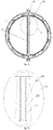
Fig. 4 is a cross-sectional view of the steam generator along a line A-A inFig. 3 ; -
Fig. 5 is an enlarged view of circled portion A inFig. 4 ; -
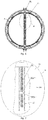
Fig. 6 is a cross-sectional view of the steam generator along a line B-B inFig. 3 ; and -
Fig. 7 is an enlarged view of circled portion B inFig. 6 . - 10-plate body; 12-three-leaf plum blossom-shaped hole; 120-boss edge; 122-side edge; 124-top edge; 14-hole bridge; 16-U-shaped heat transfer tube; 18-heat exchange fluid channel; 19-tube gallery area; 190-through hole; 1902-round hole; 1900-rectangular hole; 1- steam generator; 2- support plate; 3- support plate; 40- inspection hole.
- In order to make the objective, technical solutions and effects of the present invention clearer, the present invention will be further described in detail below in conjunction with accompanying drawings and embodiments. It should be understood that the embodiments described herein are only for explaining the present invention, not for limiting the scope of the present invention.
- Referring to
Figs. 1 to 7 , a support plate for U-shaped heat transfer tube of steam generator of nuclear power plant according to one embodiment of the present invention includes aplate body 10. Theplate body 10 defines a number of three-leaf plum blossom-shaped holes 12 extending through theplate body 10. Ahole bridge 14 is formed between two three three-leaf plum blossom-shaped holes 12. Each three-leaf plum blossom-shaped hole 12 includes aboss edge 120, aside edge 122 and atop edge 124. After the U-shapedheat transfer tube 16 is inserted into the three-leaf plum blossom-shaped hole 12, theboss edge 120 supports the tube wall of the U-shapedheat transfer tube 16, and theside edge 122 andtop edge 124 of the three-leaf plum blossom-shaped hole 12 and the tube wall of the U-shapedheat transfer tube 16 jointly enclose a heatexchange fluid channel 18 outside the U-shapedheat transfer tube 16. Atube gallery area 19 is seated in the middle of theplate body 10, and thetube gallery area 19 is provided with a number of throughholes 190. The three-leaf plum blossom-shaped holes 12 are arranged on two sides of thetube gallery area 19, wherein the included angle of connection line of the three-leaf plum blossom-shaped holes 12 and theside edge 122 corresponding thereto is α, and 0<α≤13°. - According to one embodiment of the present invention, the
plate body 10 is made from martensitic stainless steel having good corrosion resistance. Theplate body 10 has a thickness of 25mm to 35mm. - The three-leaf plum blossom-
shaped holes 12 are uniformly arranged on theplate body 10 in a regular triangle fashion. The ratio P/D of the distance P between two adjacent three-leaf plum blossom-shaped holes 12 to the outer diameter D of the U-shapedheat transfer tube 16 is 1.2 to 1.5, ensuring the U-shapedheat transfer tubes 16 can be arranged compactly, and more U-shapedheat transfer tubes 16 being arranged on a same area, which can reduce the size of the device. There is a small gap between theboss edge 120 of the three-leaf plum blossom-shaped hole 12 and the tube wall of the U-shapedheat transfer tube 16, which provides support for the U-shapedheat transfer tube 16 during the operation of the nuclear power plant, to prevent the U-shapedheat transfer tube 16 from vibrating in the three-leaf plum blossom-shaped hole 12. Theside edge 122 and thetop edge 124 of the three-leaf plum blossom-shaped hole 12 and the outer wall of the U-shapedheat transfer tube 16 jointly enclose a heatexchange fluid channel 18 for the exchange heat of the outside of the U-shapedheat transfer tube 16. - The
top edge 124 is arc shaped. The arc center of thetop edge 124 is concentric with the center of the U-shapedheat transfer tube 16. A circle arc transitions between theboss edge 120, theside edge 122 and thetop edge 124. - A
hole bridge 14 is formed between two adjacent three-leaf plum blossom-shapedholes 12. In order to ensure the strength of thehole bridge 14, the included angle of the hole bridge 14 (the included angle of connection line of the three-leaf plum blossom-shapedholes 12 and side edge corresponding thereto) α is 0<α≤13°, preferably 5°<α≤13°. In the illustrated embodiment, the included angle α is 13°. -
Figs. 3 to 5 show a first embodiment of the support plate of the present invention, i.e.support plate 2. Thetube gallery area 19 in the middle of theplate body 10 of thesupport plate 2 is provided with a number of throughholes 190. The throughholes 190 are a rectangular hole and the rectangular holes are located on the central axis of thesupport plate 2. The length of the rectangular hole is greater than the width of the rectangular hole. Preferably, the length of the rectangular hole is 3 times greater than the width of the rectangular hole, the width of the rectangular hole is smaller than the width of thetube gallery area 19, and the three-leaf plum blossom-shapedholes 12 are arranged side by side on both sides of the rectangular hole. The size of the rectangular hole is sufficient to allow the sludge washing equipment to reach each layer of thesupport plate 2 through the rectangular hole during the maintenance of the steam generator, and then wash the sludge generated on thesupport plate 2 during operation. -
Figs. 3 ,6 and 7 show a second embodiment of a support plate of the present invention, i.e.support plate 3. Thetube gallery area 19 in the middle of theplate body 10 of thesupport plate 3 is also provided with a number of throughholes 190. Throughholes 190 arerectangular holes 1900 and round holes 1902. Therectangular holes 1900 are regularly and evenly arranged on the center line of thetube gallery area 19, the round holes 1902 are the same, and therectangular holes 1900 are spaced apart from the round holes 1902. The width of theround holes 1902 arranged side by side is substantially the same as the width of therectangular holes 1900, and is smaller than the width of thetube gallery area 19. The length and width of therectangular holes 1900 are almost the same, and the width is the same as that of the rectangular hole shown inFig. 5 . The three-leaf plum blossom-shapedholes 12 are arranged side by side on both sides of theround holes 1902 and therectangular holes 1900. Due to therectangular holes 1900 andround holes 1902 on thetube gallery area 19, the water outside the U-shapedheat transfer tube 16 can be forced into the gap area of the adjacent the U-shapedheat transfer tube 16, increasing the resistance, making the circulating water in the steam generator flows to places other than thetube gallery area 19 and preventing the water from directly flowing away from thetube gallery area 19, thereby affecting the heat exchange of the U-shapedheat transfer tube 16. The size of therectangular hole 1900 and theround hole 1902 can be adjusted according to actual conditions. - The heat generated by the reactor core of the PWR nuclear power plant heats the water in the reactor pressure vessel. The heated high-temperature water flows into the U-shaped
heat transfer tube 16, and the high-temperature water in the U-shapedheat transfer tube 16 transfers the heat. The water outside the U-shapedheat transfer tube 16 is heated to generate steam to drive the steam turbine to generate electricity. Due to the impact of the water flow and steam flow outside the U-shapedheat transfer tube 16, the U-shapedheat transfer tube 16 will vibrate during operation. Therefore, it is necessary to provide several support plates (2 and/or 3) with throughholes 190 on the straight section of the U-shapedheat transfer tube 16, to limit the vibration of the U-shapedheat transfer tube 16 during operation. - Therefore, the present invention provides a steam generator 1 with a
support plate 3 installed on the upper part thereof.Several support plates 2 are installed below thesupport plate 3. The straight sections of the U-shapedheat transfer tubes 16 are inserted into corresponding three-leaf plum blossom-shapedholes 12 in thesupport plate 2 and thesupport plate 3. - By inserting the U-shaped
heat transfer tube 16 into the three-leaf plum blossom-shapedholes 12 of thesupport plates holes 12 on thesupport plate 3 and thesupport plate 2 will support the U-shapedheat transfer tubes 16 during the operation of the nuclear power plant, to provide effective support and ensure good heat transfer. At the same time, due to the rectangular holes on thesupport plate 2, during the maintenance of the steam generator 1, the sludge washing equipment is allowed to enter from theinspection hole 40, and pass through the rectangular holes in thetube gallery area 19 to reach thesupport plates 2 of each layer, and the sludge on thesupport plate 2 generated during the operation is washed. Since theuppermost support plate 3 is provided withrectangular holes 1900 andround holes 1902 on thetube gallery area 19, the water outside the U-shapedheat transfer tube 16 can be forced into the gap area between the adjacent U-shapedheat transfer tubes 16, increasing resistance and making the water circulating in the steam generator 1 flows outside thetube gallery area 19, to prevent the water flow from directly flowing away from thetube gallery area 19, so as not to affect the heat exchange of the U-shapedheat transfer tube 16 and improve the heat exchange performance of the steam generator 1. - Compared with the prior art, the support plate for U-shaped heat transfer tube of steam generator of nuclear power plant and steam generator thereof of the present invention have the following advantages:
- 1) Due to the configuration and arrangement of the three-leaf plum blossom-shaped holes, the U-shaped heat transfer tube can be arranged compactly, and more U-shaped heat transfer tubes can be arranged on the same area, thereby reducing the overall size and cost of the equipment.
- 2) The three-leaf plum blossom-shaped hole has a larger circulation area of heat exchange fluid, which can avoid evaporation of the U-shaped heat transfer tube.
- 3) Through the treatment of the special angle structure of the hole bridge of the three-leaf plum blossom-shaped hole, the support plate has good structure continuity, the strength of the weakest point is ensured, and the stress concentration and structural fatigue damage of the hole bridge structure of the support plate are reduced.
- 4) Due to the holes in the tube gallery area in the middle of the support plate, sludge generated during the operation of the support plate can be flushed with sludge washing equipment during the maintenance process, thereby avoiding adverse effect of excessive sludge deposition on the performance of the steam generator and the safety of the U-shaped heat transfer tube, and improving the thermal and hydraulic performance of the steam generator.
- Many modifications and other embodiments of the inventions set forth herein will come to mind to one skilled in the art to which these inventions pertain having the benefit of the teachings presented in the foregoing descriptions and the associated drawings. Therefore, it is to be understood that the inventions are not to be limited to the specific embodiments disclosed and that modifications and other embodiments are intended to be included within the scope of the appended claims. Moreover, although the foregoing descriptions and the associated drawings describe example embodiments, it should be appreciated that alternative embodiments without departing from the scope of the appended claims. Although specific terms are employed herein, they are used in a generic and descriptive sense only and not for purposes of limitation.
Claims (9)
- A support plate for U-shaped heat transfer tube of steam generator of nuclear power plant, comprising a plate body (10), characterized in that the plate body (10) is provided with a plurality of three-leaf plum blossom-shaped holes (12) extending through the plate body (10), a hole bridge (14) is formed between two adjacent three-leaf plum blossom-shaped holes (12), each three-leaf plum blossom-shaped hole (12) comprises a boss edge (120), a side edge (122) and a top edge (124), after the U-shaped heat transfer tube (16) is inserted into the three-leaf plum blossom-shaped hole (12), the boss edge (120) supports a tube wall of the U-shaped heat transfer tube (16), the side edge (122) and top edge (124) of the three-leaf plum blossom-shaped hole (12) and a tube wall of the U-shaped heat transfer tube (16) enclose a heat exchange fluid channel (18) outside the U-shaped heat transfer tube (16), a tube gallery area (19) is formed in the middle of the plate body (10), and the tube gallery area (19) is provided with through holes (190), the three-leaf plum blossom-shaped holes (12) are arranged on two sides of the tube gallery area (19), characterized in that an included angle of connection lines of the three-leaf plum blossom-shaped holes (12) and side edge corresponding thereto is α, and 0<α≤13°.
- The support plate for U-shaped heat transfer tube of steam generator of nuclear power plant of claim 1, characterized in that the included angle of connection line of the three-leaf plum blossom-shaped holes (12) and side edge corresponding thereto is α, and 5°≤α≤13°.
- The support plate for U-shaped heat transfer tube of steam generator of nuclear power plant of claim 1, characterized in that a ratio P/D of distance P between two adjacent three-leaf plum blossom-shaped holes (12) and outer diameter D of the U-shaped heat transfer tube is 1.2 to 1.5.
- The support plate for U-shaped heat transfer tube of steam generator of nuclear power plant of claim 1, characterized in that the plate body (10) has a thickness of 25 mm to 35mm.
- The support plate for U-shaped heat transfer tube of steam generator of nuclear power plant of claim 1, characterized in that the through holes (190) are rectangular holes (1900).
- The support plate for U-shaped heat transfer tube of steam generator of nuclear power plant of claim 1, characterized in that the through holes (190) are round holes (1902) and rectangular holes (1900).
- The support plate for U-shaped heat transfer tube of steam generator of nuclear power plant of claim 1, characterized in that the top edge (124) is arc-shaped, and an arc center of the top edge (124) is concentric with a center of the U-shaped heat transfer tube (16), and a circular arc transitions between the boss edge (120), the side edge (122) and the top edge (124).
- The support plate for U-shaped heat transfer tube of steam generator of nuclear power plant of claim 1, characterized in that the three-leaf plum blossom-shaped holes (12) are uniformly arranged on the plate body (10) in a regular triangle fashion.
- A steam generator (1), comprising: a U-shaped heat transfer tube (16) and a support plate (2,3), characterized in that the support plate (2,3) is the support plate for U-shaped heat transfer tube of steam generator of nuclear power plant according to any one of claims 1 to 8.
Applications Claiming Priority (2)
| Application Number | Priority Date | Filing Date | Title |
|---|---|---|---|
| CN201820796471.1U CN208398051U (en) | 2018-05-25 | 2018-05-25 | The effective support plate of Steam Generators in NPP U-shaped heat transfer and its steam generator |
| PCT/CN2018/118811 WO2019223282A1 (en) | 2018-05-25 | 2018-12-02 | Support plate for u-shaped heat transfer tube of steam generator of nuclear power plant and steam generator thereof |
Publications (3)
| Publication Number | Publication Date |
|---|---|
| EP3805686A1 true EP3805686A1 (en) | 2021-04-14 |
| EP3805686A4 EP3805686A4 (en) | 2022-03-02 |
| EP3805686B1 EP3805686B1 (en) | 2026-02-04 |
Family
ID=65137393
Family Applications (1)
| Application Number | Title | Priority Date | Filing Date |
|---|---|---|---|
| EP18920012.4A Active EP3805686B1 (en) | 2018-05-25 | 2018-12-02 | Support plate for u-shaped heat transfer tube of steam generator of nuclear power plant and steam generator thereof |
Country Status (3)
| Country | Link |
|---|---|
| EP (1) | EP3805686B1 (en) |
| CN (1) | CN208398051U (en) |
| WO (1) | WO2019223282A1 (en) |
Cited By (1)
| Publication number | Priority date | Publication date | Assignee | Title |
|---|---|---|---|---|
| CN113566611A (en) * | 2021-08-12 | 2021-10-29 | 上海蓝滨石化设备有限责任公司 | U-shaped pipe three-flow heat exchanger |
Families Citing this family (1)
| Publication number | Priority date | Publication date | Assignee | Title |
|---|---|---|---|---|
| CN113190927B (en) * | 2021-04-27 | 2023-08-04 | 上海核工程研究设计院股份有限公司 | Steam generator U-shaped heat transfer tube fluid bullet excitation abrasion analysis calculation method |
Family Cites Families (10)
| Publication number | Priority date | Publication date | Assignee | Title |
|---|---|---|---|---|
| US4756770A (en) * | 1986-02-11 | 1988-07-12 | Arkansas Power And Light Company | Water slap steam generator cleaning method |
| US4921662A (en) * | 1988-04-19 | 1990-05-01 | Westinghouse Electric Corp. | Pressure pulse cleaning method |
| US6498827B1 (en) * | 1999-11-01 | 2002-12-24 | Babcock & Wilcox Canada, Ltd. | Heat exchanger tube support structure |
| JP2007271157A (en) * | 2006-03-31 | 2007-10-18 | Mitsubishi Heavy Ind Ltd | Support structure for heat transfer tube |
| JP5072388B2 (en) * | 2007-02-27 | 2012-11-14 | 三菱重工業株式会社 | Steam generator tube support plate |
| US20100276550A1 (en) * | 2009-04-29 | 2010-11-04 | Klarner Richard G | Tube support structure |
| US9683732B2 (en) * | 2011-10-13 | 2017-06-20 | Westinghouse Electric Company | Anti-clogging steam generator tube bundle |
| CN203024131U (en) * | 2012-12-13 | 2013-06-26 | 中国核动力研究设计院 | Novel heat exchange tube supporting device of steam generator in pressurized water reactor nuclear power plant |
| CN203443416U (en) * | 2013-05-31 | 2014-02-19 | 茂名市茂港电力设备厂有限公司 | Shell and tube heat exchanger |
| CN204440816U (en) * | 2015-03-19 | 2015-07-01 | 中国核动力研究设计院 | A kind of steam generator heat-transfer pipe bundle analogue means |
-
2018
- 2018-05-25 CN CN201820796471.1U patent/CN208398051U/en active Active
- 2018-12-02 WO PCT/CN2018/118811 patent/WO2019223282A1/en not_active Ceased
- 2018-12-02 EP EP18920012.4A patent/EP3805686B1/en active Active
Cited By (2)
| Publication number | Priority date | Publication date | Assignee | Title |
|---|---|---|---|---|
| CN113566611A (en) * | 2021-08-12 | 2021-10-29 | 上海蓝滨石化设备有限责任公司 | U-shaped pipe three-flow heat exchanger |
| CN113566611B (en) * | 2021-08-12 | 2023-12-19 | 上海蓝滨石化设备有限责任公司 | U-shaped tube three-flow heat exchanger |
Also Published As
| Publication number | Publication date |
|---|---|
| WO2019223282A1 (en) | 2019-11-28 |
| CN208398051U (en) | 2019-01-18 |
| EP3805686B1 (en) | 2026-02-04 |
| EP3805686A4 (en) | 2022-03-02 |
Similar Documents
| Publication | Publication Date | Title |
|---|---|---|
| RU197487U1 (en) | TEE NODE FOR MIXING THE FLOWS OF THE NUCLEAR REACTOR BLOWING AND SUPPLY SYSTEM | |
| EP3805686B1 (en) | Support plate for u-shaped heat transfer tube of steam generator of nuclear power plant and steam generator thereof | |
| CN205447786U (en) | Flue gas water heat exchanger | |
| CN105023498A (en) | Steam generator test system | |
| EP4583120B1 (en) | Reactor vortex suppression and flow distribution device | |
| CN111981892A (en) | Method for judging leakage of surface type steam-water heat exchanger | |
| CN103868049B (en) | A kind of novel setting-out core power plant steam producer heat transfer tube supporting device | |
| CN103594127A (en) | Energy-saving nuclear power evaporator | |
| JP6004413B2 (en) | Tube support structure | |
| CN101551205A (en) | Spiral fin self-supporting heat exchanger | |
| CN102393159B (en) | Shell-and-tube type heat exchanger with U-shaped tube-bundle vibration-proof device | |
| CN110808108B (en) | A semi-open diversion device for direct injection of nuclear reactors | |
| CN201016589Y (en) | A shell-and-tube steam-water heat exchanger | |
| CN115371469B (en) | System and method for relieving abrasion of heat transfer tube of steam generator | |
| CN202470862U (en) | Novel baffle for heat exchanger shell heating medium inlet | |
| CN209991837U (en) | Guide plate of indirect air cooling radiator pipe box | |
| CN101033917A (en) | shell-and-tube steam and water heat exchanger | |
| CN205784799U (en) | The anti-structure of quivering of a kind of bank of condenser pipes | |
| CN212252576U (en) | Semicircular fin heat exchange tube type flue gas waste heat utilization low-temperature coal economizer | |
| EP2696137A1 (en) | Water supply pipe for vapor generator | |
| CN116146968A (en) | Anti-foreign matter device and system for the hook pipe of the secondary side water supply ring of the steam generator | |
| CN108343943B (en) | Overheating section structure for improving input rate of high-pressure heater | |
| JP6650776B2 (en) | Flow damper, accumulator water injection device and nuclear facilities | |
| CN219389881U (en) | Energy-saving efficient impact-resistant plate of heating network heater | |
| CN201653241U (en) | A point-line composite support type closed water cooler |
Legal Events
| Date | Code | Title | Description |
|---|---|---|---|
| STAA | Information on the status of an ep patent application or granted ep patent |
Free format text: STATUS: THE INTERNATIONAL PUBLICATION HAS BEEN MADE |
|
| PUAI | Public reference made under article 153(3) epc to a published international application that has entered the european phase |
Free format text: ORIGINAL CODE: 0009012 |
|
| STAA | Information on the status of an ep patent application or granted ep patent |
Free format text: STATUS: REQUEST FOR EXAMINATION WAS MADE |
|
| 17P | Request for examination filed |
Effective date: 20201222 |
|
| AK | Designated contracting states |
Kind code of ref document: A1 Designated state(s): AL AT BE BG CH CY CZ DE DK EE ES FI FR GB GR HR HU IE IS IT LI LT LU LV MC MK MT NL NO PL PT RO RS SE SI SK SM TR |
|
| AX | Request for extension of the european patent |
Extension state: BA ME |
|
| DAV | Request for validation of the european patent (deleted) | ||
| DAX | Request for extension of the european patent (deleted) | ||
| A4 | Supplementary search report drawn up and despatched |
Effective date: 20220201 |
|
| RIC1 | Information provided on ipc code assigned before grant |
Ipc: F28F 9/013 20060101AFI20220126BHEP |
|
| GRAP | Despatch of communication of intention to grant a patent |
Free format text: ORIGINAL CODE: EPIDOSNIGR1 |
|
| STAA | Information on the status of an ep patent application or granted ep patent |
Free format text: STATUS: GRANT OF PATENT IS INTENDED |
|
| INTG | Intention to grant announced |
Effective date: 20250820 |
|
| GRAS | Grant fee paid |
Free format text: ORIGINAL CODE: EPIDOSNIGR3 |
|
| GRAA | (expected) grant |
Free format text: ORIGINAL CODE: 0009210 |
|
| STAA | Information on the status of an ep patent application or granted ep patent |
Free format text: STATUS: THE PATENT HAS BEEN GRANTED |
|
| AK | Designated contracting states |
Kind code of ref document: B1 Designated state(s): AL AT BE BG CH CY CZ DE DK EE ES FI FR GB GR HR HU IE IS IT LI LT LU LV MC MK MT NL NO PL PT RO RS SE SI SK SM TR |
|
| REG | Reference to a national code |
Ref country code: CH Ref legal event code: F10 Free format text: ST27 STATUS EVENT CODE: U-0-0-F10-F00 (AS PROVIDED BY THE NATIONAL OFFICE) Effective date: 20260204 Ref country code: GB Ref legal event code: FG4D |
|
| REG | Reference to a national code |
Ref country code: DE Ref legal event code: R096 Ref document number: 602018089010 Country of ref document: DE |
|
| REG | Reference to a national code |
Ref country code: IE Ref legal event code: FG4D |