EP3805665B1 - Vortex tube, seat heating and cooling system, and seat assembly - Google Patents
Vortex tube, seat heating and cooling system, and seat assembly Download PDFInfo
- Publication number
- EP3805665B1 EP3805665B1 EP19216677.5A EP19216677A EP3805665B1 EP 3805665 B1 EP3805665 B1 EP 3805665B1 EP 19216677 A EP19216677 A EP 19216677A EP 3805665 B1 EP3805665 B1 EP 3805665B1
- Authority
- EP
- European Patent Office
- Prior art keywords
- vortex
- air
- seat
- coupled
- assembly
- Prior art date
- Legal status (The legal status is an assumption and is not a legal conclusion. Google has not performed a legal analysis and makes no representation as to the accuracy of the status listed.)
- Active
Links
Images


Classifications
-
- B—PERFORMING OPERATIONS; TRANSPORTING
- B64—AIRCRAFT; AVIATION; COSMONAUTICS
- B64D—EQUIPMENT FOR FITTING IN OR TO AIRCRAFT; FLIGHT SUITS; PARACHUTES; ARRANGEMENT OR MOUNTING OF POWER PLANTS OR PROPULSION TRANSMISSIONS IN AIRCRAFT
- B64D11/00—Passenger or crew accommodation; Flight-deck installations not otherwise provided for
- B64D11/06—Arrangements of seats, or adaptations or details specially adapted for aircraft seats
- B64D11/0626—Arrangements of seats, or adaptations or details specially adapted for aircraft seats with individual temperature or ventilation control
-
- F—MECHANICAL ENGINEERING; LIGHTING; HEATING; WEAPONS; BLASTING
- F25—REFRIGERATION OR COOLING; COMBINED HEATING AND REFRIGERATION SYSTEMS; HEAT PUMP SYSTEMS; MANUFACTURE OR STORAGE OF ICE; LIQUEFACTION SOLIDIFICATION OF GASES
- F25B—REFRIGERATION MACHINES, PLANTS OR SYSTEMS; COMBINED HEATING AND REFRIGERATION SYSTEMS; HEAT PUMP SYSTEMS
- F25B9/00—Compression machines, plants or systems, in which the refrigerant is air or other gas of low boiling point
- F25B9/02—Compression machines, plants or systems, in which the refrigerant is air or other gas of low boiling point using Joule-Thompson effect; using vortex effect
- F25B9/04—Compression machines, plants or systems, in which the refrigerant is air or other gas of low boiling point using Joule-Thompson effect; using vortex effect using vortex effect
-
- B—PERFORMING OPERATIONS; TRANSPORTING
- B60—VEHICLES IN GENERAL
- B60N—SEATS SPECIALLY ADAPTED FOR VEHICLES; VEHICLE PASSENGER ACCOMMODATION NOT OTHERWISE PROVIDED FOR
- B60N2/00—Seats specially adapted for vehicles; Arrangement or mounting of seats in vehicles
- B60N2/56—Heating or ventilating devices
- B60N2/5607—Heating or ventilating devices characterised by convection
- B60N2/5621—Heating or ventilating devices characterised by convection by air
- B60N2/5628—Heating or ventilating devices characterised by convection by air coming from the vehicle ventilation system, e.g. air-conditioning system
-
- B—PERFORMING OPERATIONS; TRANSPORTING
- B60—VEHICLES IN GENERAL
- B60N—SEATS SPECIALLY ADAPTED FOR VEHICLES; VEHICLE PASSENGER ACCOMMODATION NOT OTHERWISE PROVIDED FOR
- B60N2/00—Seats specially adapted for vehicles; Arrangement or mounting of seats in vehicles
- B60N2/56—Heating or ventilating devices
- B60N2/5607—Heating or ventilating devices characterised by convection
- B60N2/5621—Heating or ventilating devices characterised by convection by air
- B60N2/5657—Heating or ventilating devices characterised by convection by air blown towards the seat surface
-
- B—PERFORMING OPERATIONS; TRANSPORTING
- B60—VEHICLES IN GENERAL
- B60N—SEATS SPECIALLY ADAPTED FOR VEHICLES; VEHICLE PASSENGER ACCOMMODATION NOT OTHERWISE PROVIDED FOR
- B60N2/00—Seats specially adapted for vehicles; Arrangement or mounting of seats in vehicles
- B60N2/90—Details or parts not otherwise provided for
- B60N2/986—Side-rests
-
- B—PERFORMING OPERATIONS; TRANSPORTING
- B61—RAILWAYS
- B61D—BODY DETAILS OR KINDS OF RAILWAY VEHICLES
- B61D33/00—Seats
- B61D33/0007—Details; Accessories
-
- F—MECHANICAL ENGINEERING; LIGHTING; HEATING; WEAPONS; BLASTING
- F25—REFRIGERATION OR COOLING; COMBINED HEATING AND REFRIGERATION SYSTEMS; HEAT PUMP SYSTEMS; MANUFACTURE OR STORAGE OF ICE; LIQUEFACTION SOLIDIFICATION OF GASES
- F25B—REFRIGERATION MACHINES, PLANTS OR SYSTEMS; COMBINED HEATING AND REFRIGERATION SYSTEMS; HEAT PUMP SYSTEMS
- F25B29/00—Combined heating and refrigeration systems, e.g. operating alternately or simultaneously
- F25B29/003—Combined heating and refrigeration systems, e.g. operating alternately or simultaneously of the compression type system
-
- F—MECHANICAL ENGINEERING; LIGHTING; HEATING; WEAPONS; BLASTING
- F25—REFRIGERATION OR COOLING; COMBINED HEATING AND REFRIGERATION SYSTEMS; HEAT PUMP SYSTEMS; MANUFACTURE OR STORAGE OF ICE; LIQUEFACTION SOLIDIFICATION OF GASES
- F25B—REFRIGERATION MACHINES, PLANTS OR SYSTEMS; COMBINED HEATING AND REFRIGERATION SYSTEMS; HEAT PUMP SYSTEMS
- F25B9/00—Compression machines, plants or systems, in which the refrigerant is air or other gas of low boiling point
- F25B9/002—Compression machines, plants or systems, in which the refrigerant is air or other gas of low boiling point characterised by the refrigerant
- F25B9/004—Compression machines, plants or systems, in which the refrigerant is air or other gas of low boiling point characterised by the refrigerant the refrigerant being air
Definitions
- Vortex tubes are generally constructed without moving parts and are configured to separate a rotating column of air into hot and cold air streams, the proportions and temperatures of which can be varied over a wide range.
- a vortex tube can be utilized to climatize a seat.
- DE 43 45 137 A1 relates to a cooling device using an exothermic dynamic expansion process.
- Conventional vortex tubes include a single vortex generation chamber. Compressed air entering an air inlet is directed toward the vortex generation chamber to create a rotating column of air and separate the rotating column of air into hot and cold air streams.
- the hot and cold air streams travel along a length of an air circulating tube coupled to the vortex generation chamber such that hot air travels in an outer vortex in one direction of the tube while cold air travels in an inner vortex in a reverse direction of the tube. Hot air is discharged through one end of the device while cold air is discharged through an opposing end of the device.
- the air inlet is oriented such that compressed air is sprayed perpendicular (i.e., normal) to the longitudinal axis of the vortex generation chamber.
- This configuration requires high pressure to generate the necessary air speed in the vortex generation chamber to create large temperature differentials and flow rates. While high pressure systems may be acceptable in certain applications such as industrial cooling, high pressure is undesirable in applications such as seat climatization.
- the present invention provides a vortex tube including a main body having a cylindrical vortex chamber for generating a main vortex, a cylindrical air circulation chamber coaxial with the vortex chamber, and a compressed air inlet coupled in fluid communication to the vortex chamber for generating a pre-vortex in an inflow of compressed air in a direction of flow of the main vortex.
- the vortex tube further includes a vortex generator disposed in the vortex chamber of the main body, a hot air outlet disposed at a first end of the main body, and a cold air outlet disposed at a second end of the main body.
- the compressed air inlet includes a fluid passageway having an inlet port disposed outside of the vortex chamber, a tangential outlet port disposed in fluid communication with the vortex chamber, and an arcuate portion extending between the inlet port and the tangential outlet port.
- the inlet port and the tangential outlet port are longitudinally spaced along the longitudinal axis of the vortex chamber, the arcuate portion tracks circumferentially around a portion of the main body outside the vortex chamber, and the arcuate portions extends towards the air circulation chamber.
- the main body includes a first portion forming the cylindrical vortex chamber and a second portion forming the air circulation chamber, and wherein the first and second portions are coupled together or are integrally formed.
- the vortex tube has an operating range less than about 207 kPa (30 psi) and less than about 113 liters per minute (4 CFM).
- the hot air outlet includes an adjusting valve and the cold air outlet includes a nozzle.
- an embodiment of the present invention provides a seat heating and cooling system including a vortex tube according to the invention, a manifold assembly having a hot air inlet coupled in fluid communication to a hot air outlet of the vortex tube and a cold air inlet coupled in fluid communication to a cold air outlet of the vortex tube, at least one duct coupled in fluid communication to the manifold assembly for delivery hot or cold air to a seat assembly, and a controller for controlling passage of hot and cold air flow through the manifold assembly.
- the seat assembly includes a compressed air inlet coupled in fluid communication to a source of compressed air
- the seat assembly includes a manifold which operates to supply hot air to the at least one duct, cold air to the at least one duct, and a mix of hot air and cold air to the at least one duct.
- the seat assembly includes a seat cushion having spacer mesh and a perforated dress cover, and wherein the at least one duct has an end directed hot or cold air into an interior of the spacer mesh to be dispersed through the perforated dress cover.
- the manifold operates to supply hot airto the at least one duct, cold air to the at least one duct, and a mix of hot air and cold air to the at least one duct.
- the controller is disposed in the seat assembly or proximate the seat assembly.
- Embodiments of the present invention comprise a vortex tube with at least all features set out in appended independent claim 1.
- the present invention is directed to vortex tube assemblies, passenger seat constructions, and systems for climatizing passenger seats utilizing a vortex tube as a single unit for providing both heating and cooling, among other aspects comprising the vortex tube of the present invention.
- the systems disclosed herein are suitable for use in a variety of local environment conditioning applications and therefore find widespread application to passenger vehicles such as aircraft, for example, in premium and economy class aircraft passenger seats, among crew seats and others.
- the systems and components disclosed herein can be integrated into seat constructions mutually exclusive of adjustment and other capabilities of a seat.
- the systems according to the present invention can be used to condition seat elements as well as other furniture, vehicle environments, etc.
- Vortex tube assemblies according to the present invention improve on the inefficiencies of conventional vortex tubes by adding a second stage or "pre-vortex" to the main or primary vortex generation. More specifically, whereas conventional vortex tubes introduce compressed air normal (i.e., perpendicular) to the vortex generator veins, vortex tubes according to the present invention introduce compressed air tangentially and with axial momentum to the vortex generator veins, thus allowing the introduced air to maintain momentum (dynamic pressure) as the air passes from the outlet port to the innerveins of the vortex generator. Such a configuration significantly improves the efficiency of the device by eliminating flow restrictions and thereby allowing vortex generation with low pressure and flow rate.
- the vortex tube assembly 20 includes a main body 22 forming the primary or main vortex generation chamber 24 for generating the main vortex. Disposed within the main vortex generation chamber 24 is a vortex generator 26 having vortex generator veins 28 formed at one end thereof. As pressurized air is introduced into the main vortex generation chamber 24, a rotating column of air is created and separated into hot and cold air streams.
- the main body 22 further includes a pre-vortex generation chamber 30 in the form of a compressed air inlet 32.
- the compressed air inlet 32 may be coupled to or integrally formed with the main body 22.
- the compressed air inlet 32 generally includes a fluid passageway 34 having an inlet port 36 disposed outside of the main vortex generation chamber 24, a tangential outlet port 38 disposed in fluid communication with the main vortex generation chamber 24, and an arcuate portion 40 extending between the inlet port 36 and the tangential outlet port 38.
- the inlet port 36 and the tangential outlet port 38 of the compressed air inlet 32 are longitudinally spaced along the longitudinal axis of the main vortex generation chamber 24 such that the intermediate arcuate portion 40 of the air inlet tracks circumferentially around apportion of the main body 22 and in a direction toward the air circulation chamber discussed further below.
- the inlet port 36 is coupled in fluid communication to a supply of pressurized air, and as shown, is internally threaded to receive an externally threaded end of a supply conduit supplying a flow of pressurized air from an air supply.
- pressurized air introduced through the compressed air inlet 32 enters the outer portion of the main vortex generation chamber and flows in the direction of the flow of air within in the main vortex generation chamber, for example clockwise as illustrated in FIG. 1 .
- the flow direction and tangential disposition of the outlet port 38 allows the air speed of the introduced air to be maintained and sustained as the air enters the main vortex generation chamber 24.
- the increased air speed of the entering air provides for large temperature differentials with reduced pressure (e.g., less than about 207 kPa (30 psi)) and flow rate (e.g., less than about 113 liters per minute (4CFM)) as compared to conventional vortex tube operating pressures and flow rates.
- reduced pressure e.g., less than about 207 kPa (30 psi)
- flow rate e.g., less than about 113 liters per minute (4CFM)
- the vortex tube assembly 20 is structured around the main body 22.
- the main body 22 may be formed from a first portion 42 and a second portion 44, wherein the first and second portions may be coupled together or integrally formed as shown.
- Each of the first and second portions 42, 44 may be cylindrical or have a different shape.
- the first portion 42 forms the cylindrical main vortex generation chamber24, while the second portion 44 forms an elongate cylindrical air circulation tube or chamber 46.
- the main vortex generation chamber 24 and the air circulation tube 46 are fluidly coupled and axially aligned such that the vortices of air produced in the main vortex generation chamber 24 travel toward and along the length of the air circulation tube 46, with the hot air vortex traveling in an outer vortex in a first direction of the tube (to the right as viewed in FIGS. 2-5 ) and the cold air vortex traveling in an inner vortex in a reverse direction of the tube (to the left as viewed in FIGS. 2-5 ).
- An adjustment valve 48 is coupled to one end of the main body 22 for discharging hot air.
- a nozzle 50 is coupled to the opposite end of the main body 22 for discharging cold air.
- the adjustment valve 48 may be coupled via an internally threaded nut 52, having an axial passage therethrough, that threadably engages an externally threaded end 54 of the second portion 44 of the main body 22.
- the adjustment valve 48 may have a tip 58 formed at one end with a transverse air inlet 60 near the tip end in fluid communication with an axial passage 62 through the adjustment valve 48. In use, the tip end engages a restrictor64 such that the tip end can be advanced or withdrawn with respect to the restrictor62 to control the volume of airflow through the adjustment valve.
- the vortex generator 26 is disposed partially within the first portion 42 of the main body 22. More specifically, the end of the vortex generator 26 having the formed veins faces and is in axial alignment with the air circulation chamber, configured as a tube, 46. An axial passage 66 is formed through the length vortex generator 26 to allow cold air to flow therethrough. The end of the vortex generator 26 opposite the formed veins is disposed in a sleeve 68 having an axial passageway 70 therethrough. The sleeve 68 has an internal diameter corresponding to the external diameter of the tube of the vortex generator 26, and an end opening 72. Cold air traveling along the axial passage 66 of the vortex generator 26 travels through the opening 72 and ultimately out an axial passage through the nozzle 50.
- the sleeve 68 may have first and second spaced external threadings 74, 76, with one threading 74 threadably engaging in the end of the first portion 42 of the main body to capture the vortex generator26, and the other threading 76 threadably engaging in one end of the nozzle 50 to couple the nozzle to the main body 22.
- the distal ends of each of the adjustment valve 48 and the nozzle 50 may have gripping barbs 78 for securing a conduit such as a length of tubing as discussed further below.
- FIGS. 6 and 7 illustrate a non-limiting example of a one-piece construction for the main body 22.
- the first portion 42, second portion 44, and the compressed air inlet 32 may be integrally formed, such as molded as a single body.
- the first and second portions 42, 44 are disposed at opposing ends of the main body 22.
- the first portion 42 forms the main vortex generation chamber 24, the compressed air inlet 32, and internal threading 80 for threadably engaging structure, such as the sleeve, to couple the nozzle directly or indirectly to the main body 22.
- FIGS. 6 and 7 illustrate a non-limiting example of a one-piece construction for the main body 22.
- the first portion 42, second portion 44, and the compressed air inlet 32 may be integrally formed, such as molded as a single body.
- the first and second portions 42, 44 are disposed at opposing ends of the main body 22.
- the first portion 42 forms the main vortex generation chamber 24, the compressed air inlet 32, and internal threading 80 for threadably engaging structure
- Z the inlet port 36 and tangential outlet port 38 are spaced apart along the longitudinal length of the main vortex generation chamber 24 such that the intermediate arcuate portion 40 extends therebetween.
- the tangential outlet port 38 is disposed nearer the second portion 44 as compared to the inlet port 36 such that the arcuate portion 40 tracks circumferentially around in the main body toward the second portion 44, and particularly, toward the air circulation tube.
- FIGS. 8 and 9 illustrate a non-limiting example of a one-piece construction of the vortex generator 26.
- the vortex generator 26 is an elongate unitary body having a stem 82 formed at one end and an enlarged head 84 formed at an opposing end.
- the plurality of vortex generator veins 28 are formed in the face of the enlarged head and are disposable in the assembly facing the air circulation tube.
- the cold air passage 66 extends the longitudinal length of the body and may have a conical taper in the direction of the enlarged head 84.
- the vortex tube assemblies 20 may be utilized in seat climatization application, for example, the seat climatization system shown at reference numeral 100.
- the system 100 generally includes a seat 102 having a backrest cushion assembly 104 and a seat bottom cushion assembly 106.
- a backrest structural element 108 supports the backrest cushion assembly 104.
- a seat pan 110 or the like supports the seat bottom cushion assembly 106.
- Each of the backrest structural element 108 and the seat pan 110 are constructed from rigid materials such as composites to support their respective flexible cushion assembly.
- Each of the backrest cushion assembly 104 and the seat bottom cushion assembly 106 can be covered with a dress cover 112 for comfort, performance and aesthetics.
- All or portions of the dress cover 112 can be perforated to release conditioned air from within the cushion assembly through the perforated surface.
- perforated portions correspond to predetermined target areas, for example, perforations are provided in one or more of upper and lower portions of the front face of the backrest dress cover and a top portion of the seat bottom dress cover.
- the construction and configuration of the backrest structural element 108 and the seat pan 110 may vary.
- the two components may be continuous across the respective back and bottom of the seat or may be skeletal elements supporting a diaphragm.
- the two components may be pivotally coupled such that the backrest can pivot to relative to the seat bottom to recline the seat.
- the components may be pivotally coupled to each other or to other frame elements such as seat spreaders.
- the inclination of the backrest may be adjusted and locked relative to the seat bottom.
- a gas compression spring may act between the backrest and the frame with a release positioned in the armrest actuated to unlock the gas spring through a lever and Bowden cable arrangement, among other arrangements.
- a control panel may be electrically coupled to one or seat actuators dedicated for driving component adjustability either alone or together to achieve predetermined sitting positions.
- the systems disclosed herein may operate together with or mutually exclusive of seat adjustment systems.
- each of the backrest cushion assembly 104 and the seat bottom cushion assembly 106 can be constructed using a combination of materials.
- the cushion assemblies include one or more layers of open-cell foam and closed-cell flotation foam with optional fire-resistant layers or additives, referred to herein collectively as the "foam" portion of the cushion assembly.
- Cushion assemblies can optionally include spacer mesh 114 positioned in predetermined areas of the cushion assembly.
- spacer mesh may be a three-dimensional mesh like body attached to or embedded within the foam to prevent the spacer mesh from being displaced with respect to the foam body.
- the spacer mesh is positioned in ventilated regions of the cushion assembly and the foam is positioned outside of ventilated regions of the cushion assembly.
- the open-cell structure of the spacer mesh allows better air flow and dispersion therethrough.
- Some spacer mesh within the cushion assembly may be positioned near a front of the cushion assembly to direct air flow out through the perforated dress cover and across the passenger.
- Other spacer mesh may be positioned internal to the seat cushion assembly.
- Ventilated regions may correspond to surfaces of likely passenger contact.
- spacer mesh is provided in at least one of a lower backrest or lumbar region 116, an upper backrest region 118, side bolster regions 120, and a headrest region 122.
- spacer mesh may be positioned in a top surface of a central region 124 of the seat bottom. While the positioning of the spacer mesh may correspond to regions of the cushion assembly likely to be in passenger contact in different sitting positions, the spacer mesh may also be positioned to one or more the lateral sides and longitudinal ends in embodiments functioning to move airthrough the cushion assembly in general.
- the properties of the foam may provide better comfort performance as compared to the spacer mesh, while the open-cell structure of the spacer mesh may provide better airflow performance as compared to the foam.
- comfort differences between the two foam types may be imperceptible to the passenger, particularly when positioned beneath a seat dress cover.
- Each of the foam and the spacer mesh may be formed with contouring and concave portions to conform to passenger anatomy. Portions of the spacer mesh adjacent the foam may be sealed to prevent air leakage.
- the face(s) of the spacer mesh facing away from the passenger may be sealed such that air contained in the spacer mesh is directed out through the unsealed face toward the passenger.
- a source of pressurized air 126 such as an air compressor or vehicle air system (e.g., vehicle HVAC system), supplies pressurized air to the compressed air inlet 32 of the vortex tube assembly 20.
- Pressurized air entering the vortex tube 20 is accelerated along the length of the tube and separated into a hot air stream (i.e., air temperature above ambient air temperature) discharged out a first end of the tube through the adjustment valve 48 and a cold air stream (i.e., air temperature below ambient air temperature) discharged out a second end of the tube through the nozzle 50.
- a hot air stream i.e., air temperature above ambient air temperature
- a cold air stream i.e., air temperature below ambient air temperature
- the adjustment valve 48 is coupled via a first conduit 128, for example a tube, to a hot air inlet 130 of a manifold assembly 132 or the like, and the nozzle 50 is coupled via a second conduit 134, for example a tube, to a cold air inlet 136 of the same manifold assembly.
- the manifold assembly 132 operates to control the passage and mixing of hot and cold air flow therethrough and can include butterfly valves or the like for mixing hot and cold air together or with ambient air to produce conditioned air, which flows out through a duct or network of conduits 138 for dispersal through the spacer mesh.
- the manifold assembly 132 may include multiple conditioned air outlets 140, with each outlet coupled in fluid communication to a conduit having a portion of its length embedded in the cushion assembly and a dispersing portion positioned in the spacer mesh. A plurality of openings may be provided along the length of each duct for reducing air pressure of the dispersed conditioned air.
- the manifold assembly 132 may further include an air return or exhaust 142 coupled in fluid communication to the source of the pressurized air, the vehicle HVAC system, the cabin environment, or elsewhere.
- the source of pressurized air 126 may be an air compressor dedicated to the seat climatization system(s). Each seat may be equipped with its own air compressor or multiple seats may draw air from a central compressor. Compressor performance is determinative of the achievable temperature range, with a direct relationship between temperature and pressure.
- about 34.5 kPa (5psi) may produce a temperature range from about 17°C (62°F) to about 36°C (97°F), while about 138 kPa (20psi) may produce a temperature range from about 10°C (50°F) to about 66°C (150°F).
- Alternative sources of pressurized air can include, but are not limited to, a pump, aircraft air supply, etc.
- each of the compressors may be located with the seat assembly, such as below the seat pan or backrest structural element.
- the manifold assembly may be attached directly to the air compressor or may be removed therefrom and coupled in fluid communication thereto with an air conduit, such as an air hose or the like, so that the manifold assembly and the air compressor can be located in two different locations with respect to the seat assembly because of packaging constraints.
- An electric motor of the air compressor is activated to generate a supply of pressurized air.
- the air compressor can include a pressure regulator and pressure gauges to control the amount of pressure provided to the manifold assembly.
- the air compressor may or may not include a small volume air storage tank providing a reservoir for storing air under pressure for immediate seat ventilation performance on demand.
- the air compressor may regularly cycle on and off to replenish the supply of air in the tank when the tank reaches a predetermined low-pressure point.
- the air compressor may activate with a control command to supply air and deactivate with a control command to discontinue supplying air.
- the manifold assembly 132 can include a safety pressure release valve for releasing pressure from within the manifold assembly.
- the manifold assembly 132 generally operates to control and distribute heated or cooled conditioned air to the conduit network(s) 138.
- the manifold assembly 132 generally includes the hot and cold air inlets 130, 136 coupled in fluid communication to the hot and cold air outlets, such as the adjustment valve 48 and nozzle 50 of the vortex tube assembly 20. Additional outlet ports may be provided on the manifold assembly to provide conditioned air to a second seat or allow for future expansion of the system.
- a pressure regulator assembly may be incorporated into the manifold assembly including one or more valves opened or closed by actuating the controller to regulate the pressure of the flowing air at the one or more outlet ports. For example, it may be desirable to provide the same or different air flow rates through the backrest and seat bottom. It may also be necessary to provide more air flow to ducts having a long length or bends.
- the network of conduits 138 generally includes one or more lengths of air duct, such as air tubing or hose, extending between an outlet port on the manifold assembly and a portion of the cushion assembly.
- Each length of air conduit may be a direct run or may be split to disperse air different portions of the cushion assembly.
- the air conduits may be routed through the respective cushion assembly, between the cushion assembly and its respective supporting element, of within passages defined along a face of the supporting element.
- passages are formed in a frontside of the structural frame element recessed from a front planar face of the element. Each passage can have a depth corresponding to substantially a thickness of the air hose.
- the passages are shaped and directed from an air conduit entry point of the element to a target region in one of the aforementioned target regions, among others.
- the air conduits can be constructed from rigid tubing section joined together with connectors for providing directional changes.
- Each air conduit can be open at its distal end, and elsewhere, within the target region to disperse air flow throughout the respective target region.
- a controller 144 operates the manifold assembly 132, manually or by electronic control, and in some embodiments also activates the pressurized air supply 126.
- the controller 144 may be operatively coupled to or an integral part of a passenger seat control interface.
- the control interface may be located in the seat assembly or in proximity thereto.
- the control interface may be collocated with the seat control features such that all seat comfort controls are provided in the same passenger accessible device.
- Ventilation system controls may include, but are not limited to, one or more of activating airflow, adjusting output, selecting a target region(s) to be conditioned, temperature control, etc.
- Each passenger control interface may be networked with a master crew controller capable of overriding each individual seat controller. For example, all ventilation systems may be deactivated during taxi, takeoff and landing and permitted to be selectively activated during flight.
- the system includes at least one sensor positioned in the seat assembly communicatively coupled to the controller 144.
- the sensor may be a temperature sensor, air flow sensor, or both.
- the sensor may send signals to the controller regarding a sensed condition to provide automatic conditioning in response to exceeding a predetermined threshold value, such as a predetermined threshold temperature.
- Each sensor may be a device or a subsystem capable of detecting condition changes within the seat assembly and with a processor within or in communication with the controller.
- the system sensors relay information to the processor where processing logic analyzes the data received to control the system.
- the processor may be a component of a server, such as a digital computer also including input/output (I/O) interfaces, a network interface, a data store, and memory.
- I/O input/output
- the components may be communicatively coupled via a local interface such as one or more buses or other wired or wireless connections.
- the local interface may have additional elements such as controllers, buffers (caches), drivers, repeaters, and receivers, among others, to enable communications. Further, the local interface may include address, control, and/or data connections to enable appropriate communications among the components.
- the processor is a hardware device for executing software instructions such as collation algorithms.
- the processor may be any custom made or commercially available processor, a central processing unit (CPU), an auxiliary processor among several processors associated with the server, a semiconductor-based microprocessor (in the form of a microchip or chip set), or generally any device for executing software instructions.
- the processor is configured to execute software stored within the memory, to communicate data to and from the memory, and to generally control operations of the server pursuant to the software instructions.
- the I/O interfaces may be used to receive user input from and/or for providing system output to one or more devices or components such as the described or inferred sensors, an aircraft network, and flight crew devices.
- I/O interfaces may include a serial port, a parallel port, a small computer system interface (SCSI), a serial ATA (SATA), a fibre channel, Infiniband, iSCSI, a PCI Express interface (PCI-x), an infrared (IR) interface, a radio frequency (RF) interface, and/or a universal serial bus (USB) interface.
- SCSI small computer system interface
- SATA serial ATA
- PCI-x PCI Express interface
- IR infrared
- RF radio frequency
- USB universal serial bus
- a network interface may be used to enable the server to communicate on a network, such as the Internet, a wide region network (WAN), a local region network (LAN) such as the secure aircraft network, and the like, etc.
- the network interface may include address, control, and/or data connections to enable appropriate communications on the network.
- a data store may be used to store data.
- the data store may include any of volatile memory elements (e.g., random access memory (RAM, such as DRAM, SRAM, SDRAM, and the like)), nonvolatile memory elements (e.g., ROM, hard drive, tape, CDROM, and the like), and combinations thereof.
- the data store may be located internal to the server such as, for example, an internal hard drive connected to the local interface in the server.
- the data store may be located external to the server such as, for example, an external hard drive connected to the I/O interfaces (e.g., SCSI or USB connection).
- the data store may be connected to the server through a network, such as, for example, a network attached file server.
- the software in memory may include one or more software programs, each of which includes an ordered listing of executable instructions for implementing logical functions.
- the software in the memory includes a suitable operating system (O/S) and one or more programs.
- the operating system essentially controls the execution of other computer programs, such as the one or more programs, and provides scheduling, input-output control, file and data management, memory management, and communication control and related services.
- the one or more programs may be configured to implement the various processes, algorithms, methods, techniques, etc. described or inferred herein.
Landscapes
- Engineering & Computer Science (AREA)
- Mechanical Engineering (AREA)
- Aviation & Aerospace Engineering (AREA)
- Physics & Mathematics (AREA)
- Thermal Sciences (AREA)
- General Engineering & Computer Science (AREA)
- Transportation (AREA)
- Seats For Vehicles (AREA)
- Air-Conditioning For Vehicles (AREA)
- Chair Legs, Seat Parts, And Backrests (AREA)
Description
- The present invention is directed to a vortex tube.
- Local heating and cooling can be accomplished with various devices configured to move a volume of air. One such device is a vortex tube. Vortex tubes are generally constructed without moving parts and are configured to separate a rotating column of air into hot and cold air streams, the proportions and temperatures of which can be varied over a wide range. In one application, a vortex tube can be utilized to climatize a seat.
-
DE 43 45 137 A1 relates to a cooling device using an exothermic dynamic expansion process. -
US 2002/145312 A1 relates to seats that utilize a vortex tube as a source of hot and cold air streams for heating and cooling the seat surface. - Conventional vortex tubes include a single vortex generation chamber. Compressed air entering an air inlet is directed toward the vortex generation chamber to create a rotating column of air and separate the rotating column of air into hot and cold air streams. The hot and cold air streams travel along a length of an air circulating tube coupled to the vortex generation chamber such that hot air travels in an outer vortex in one direction of the tube while cold air travels in an inner vortex in a reverse direction of the tube. Hot air is discharged through one end of the device while cold air is discharged through an opposing end of the device.
- In conventional vortex tubes the air inlet is oriented such that compressed air is sprayed perpendicular (i.e., normal) to the longitudinal axis of the vortex generation chamber. This configuration requires high pressure to generate the necessary air speed in the vortex generation chamber to create large temperature differentials and flow rates. While high pressure systems may be acceptable in certain applications such as industrial cooling, high pressure is undesirable in applications such as seat climatization.
- Accordingly, what is needed is a more efficient vortex tube construction for low pressure and low flow rate applications.
- To achieve the foregoing, the present invention, as defined by appended independent claim 1 and representing a first aspect, provides a vortex tube including a main body having a cylindrical vortex chamber for generating a main vortex, a cylindrical air circulation chamber coaxial with the vortex chamber, and a compressed air inlet coupled in fluid communication to the vortex chamber for generating a pre-vortex in an inflow of compressed air in a direction of flow of the main vortex. The vortex tube further includes a vortex generator disposed in the vortex chamber of the main body, a hot air outlet disposed at a first end of the main body, and a cold air outlet disposed at a second end of the main body.
- The compressed air inlet includes a fluid passageway having an inlet port disposed outside of the vortex chamber, a tangential outlet port disposed in fluid communication with the vortex chamber, and an arcuate portion extending between the inlet port and the tangential outlet port.
- The inlet port and the tangential outlet port are longitudinally spaced along the longitudinal axis of the vortex chamber, the arcuate portion tracks circumferentially around a portion of the main body outside the vortex chamber, and the arcuate portions extends towards the air circulation chamber.
- In some embodiments, the main body includes a first portion forming the cylindrical vortex chamber and a second portion forming the air circulation chamber, and wherein the first and second portions are coupled together or are integrally formed.
- In some embodiments, the vortex generator includes a body having an axial passageway therethrough and a plurality of veins formed at one end of the body.
- In some embodiments, the vortex tube has an operating range less than about 207 kPa (30 psi) and less than about 113 liters per minute (4 CFM).
- In some embodiments, the hot air outlet includes an adjusting valve and the cold air outlet includes a nozzle.
- In a second aspect, an embodiment of the present invention provides a seat heating and cooling system including a vortex tube according to the invention, a manifold assembly having a hot air inlet coupled in fluid communication to a hot air outlet of the vortex tube and a cold air inlet coupled in fluid communication to a cold air outlet of the vortex tube, at least one duct coupled in fluid communication to the manifold assembly for delivery hot or cold air to a seat assembly, and a controller for controlling passage of hot and cold air flow through the manifold assembly.
- In some embodiments, the seat heating and cooling system includes a compressed air source for supplying compressed air to the air inlet of the vortex tube.
- In a third aspect, an embodiment of the present invention provides a passenger seat assembly including a cushion having spacer mesh and a heating and cooling system according to the second aspect of the present invention, thus comprising the vortex tube as defined by appended independent claim 1, having at least one duct coupled in fluid communication to the manifold assembly for delivery hot or cold air into an interior of the spacer mesh.
- In some embodiments, the seat assembly includes a compressed air inlet coupled in fluid communication to a source of compressed air In some embodiments, the seat assembly includes a manifold which operates to supply hot air to the at least one duct, cold air to the at least one duct, and a mix of hot air and cold air to the at least one duct.
- In some embodiments, the seat assembly includes a seat cushion having spacer mesh and a perforated dress cover, and wherein the at least one duct has an end directed hot or cold air into an interior of the spacer mesh to be dispersed through the perforated dress cover.
- In some embodiments, the seat cushion is disposed in a backrest and the spacer mesh is disposed in at least one of an upper portion of the backrest and a lower portion of the backrest.
- In some embodiments, the seat cushion is disposed in a seat bottom, or seat pan, and the spacer mesh is disposed in an upper portion of the seat bottom.
- In some embodiments, the manifold operates to supply hot airto the at least one duct, cold air to the at least one duct, and a mix of hot air and cold air to the at least one duct.
- In some embodiments, the controller is disposed in the seat assembly or proximate the seat assembly.
- Embodiments of the present invention comprise a vortex tube with at least all features set out in appended independent claim 1.
- The present invention may be better understood when consideration is given to the following detailed description thereof. Such description makes reference to the included drawings, which are not necessarily to scale, and in which some features may be exaggerated and some features may be omitted or may be represented schematically in the interest of clarity. Like reference numerals in the drawings may represent and refer to the same or similar element, feature, or function. In the drawings:
-
FIG. 1 is a conceptual cross-sectional view of a vortex tube according to the present invention illustrating a main vortex and a pre-vortex; -
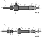
FIG. 2 is a side view of a vortex tube assembly according to the present invention; -
FIG. 3 is an exploded side view of the vortex tube assembly ofFIG. 2 ; -
FIG. 4 is a longitudinal cross-sectional view of the vortex tube assembly ofFIG. 2 ; -
FIG. 5 is an exploded longitudinal cross-sectional view of the vortex tube assembly ofFIG. 3 ; -
FIG. 6 is a perspective view of a main body of the vortex tube assembly; -
FIG. 7 is a longitudinal cross-sectional view of the main body ofFIG. 6 ; -
FIG. 8 is a perspective view of a vortex generator of the vortex tube assembly; -
FIG. 9 is a cross-sectional view of the vortex generator ofFIG. 8 ; and -
FIG. 10 is a schematic illustration of a seat system heated and cooled using a vortex tube according to the present invention. - The description set forth below in connection with the appended drawings is intended to be a description of various, illustrative embodiments of the disclosed subject matter.
- The present invention is directed to vortex tube assemblies, passenger seat constructions, and systems for climatizing passenger seats utilizing a vortex tube as a single unit for providing both heating and cooling, among other aspects comprising the vortex tube of the present invention. The systems disclosed herein are suitable for use in a variety of local environment conditioning applications and therefore find widespread application to passenger vehicles such as aircraft, for example, in premium and economy class aircraft passenger seats, among crew seats and others. The systems and components disclosed herein can be integrated into seat constructions mutually exclusive of adjustment and other capabilities of a seat. The systems according to the present invention can be used to condition seat elements as well as other furniture, vehicle environments, etc.
- Vortex tube assemblies according to the present invention improve on the inefficiencies of conventional vortex tubes by adding a second stage or "pre-vortex" to the main or primary vortex generation. More specifically, whereas conventional vortex tubes introduce compressed air normal (i.e., perpendicular) to the vortex generator veins, vortex tubes according to the present invention introduce compressed air tangentially and with axial momentum to the vortex generator veins, thus allowing the introduced air to maintain momentum (dynamic pressure) as the air passes from the outlet port to the innerveins of the vortex generator. Such a configuration significantly improves the efficiency of the device by eliminating flow restrictions and thereby allowing vortex generation with low pressure and flow rate.
- Referring to
FIG. 1 , a conceptual illustration of part of a vortex tube assembly according to the present invention is shown atreference numeral 20. Thevortex tube assembly 20 includes amain body 22 forming the primary or mainvortex generation chamber 24 for generating the main vortex. Disposed within the mainvortex generation chamber 24 is avortex generator 26 havingvortex generator veins 28 formed at one end thereof. As pressurized air is introduced into the mainvortex generation chamber 24, a rotating column of air is created and separated into hot and cold air streams. Themain body 22 further includes apre-vortex generation chamber 30 in the form of acompressed air inlet 32. Thecompressed air inlet 32 may be coupled to or integrally formed with themain body 22. - The
compressed air inlet 32 generally includes afluid passageway 34 having aninlet port 36 disposed outside of the mainvortex generation chamber 24, atangential outlet port 38 disposed in fluid communication with the mainvortex generation chamber 24, and anarcuate portion 40 extending between theinlet port 36 and thetangential outlet port 38. As discussed further below, theinlet port 36 and thetangential outlet port 38 of thecompressed air inlet 32 are longitudinally spaced along the longitudinal axis of the mainvortex generation chamber 24 such that the intermediatearcuate portion 40 of the air inlet tracks circumferentially around apportion of themain body 22 and in a direction toward the air circulation chamber discussed further below. Theinlet port 36 is coupled in fluid communication to a supply of pressurized air, and as shown, is internally threaded to receive an externally threaded end of a supply conduit supplying a flow of pressurized air from an air supply. - Based on the angle and orientation of the
outlet port 38 tangent to the wall of the main vortex generation chamber24, pressurized air introduced through thecompressed air inlet 32 enters the outer portion of the main vortex generation chamber and flows in the direction of the flow of air within in the main vortex generation chamber, for example clockwise as illustrated inFIG. 1 . The flow direction and tangential disposition of theoutlet port 38 allows the air speed of the introduced air to be maintained and sustained as the air enters the mainvortex generation chamber 24. The increased air speed of the entering air provides for large temperature differentials with reduced pressure (e.g., less than about 207 kPa (30 psi)) and flow rate (e.g., less than about 113 liters per minute (4CFM)) as compared to conventional vortex tube operating pressures and flow rates. - Referring to
FIGS. 2-5 , thevortex tube assembly 20 is structured around themain body 22. Themain body 22 may be formed from afirst portion 42 and asecond portion 44, wherein the first and second portions may be coupled together or integrally formed as shown. Each of the first andsecond portions first portion 42 forms the cylindrical main vortex generation chamber24, while thesecond portion 44 forms an elongate cylindrical air circulation tube orchamber 46. The mainvortex generation chamber 24 and theair circulation tube 46 are fluidly coupled and axially aligned such that the vortices of air produced in the mainvortex generation chamber 24 travel toward and along the length of theair circulation tube 46, with the hot air vortex traveling in an outer vortex in a first direction of the tube (to the right as viewed inFIGS. 2-5 ) and the cold air vortex traveling in an inner vortex in a reverse direction of the tube (to the left as viewed inFIGS. 2-5 ). - An
adjustment valve 48 is coupled to one end of themain body 22 for discharging hot air. Anozzle 50 is coupled to the opposite end of themain body 22 for discharging cold air. Theadjustment valve 48 may be coupled via an internally threadednut 52, having an axial passage therethrough, that threadably engages an externally threadedend 54 of thesecond portion 44 of themain body 22. Theadjustment valve 48 may have atip 58 formed at one end with atransverse air inlet 60 near the tip end in fluid communication with anaxial passage 62 through theadjustment valve 48. In use, the tip end engages a restrictor64 such that the tip end can be advanced or withdrawn with respect to the restrictor62 to control the volume of airflow through the adjustment valve. - The
vortex generator 26 is disposed partially within thefirst portion 42 of themain body 22. More specifically, the end of thevortex generator 26 having the formed veins faces and is in axial alignment with the air circulation chamber, configured as a tube, 46. Anaxial passage 66 is formed through thelength vortex generator 26 to allow cold air to flow therethrough. The end of thevortex generator 26 opposite the formed veins is disposed in asleeve 68 having anaxial passageway 70 therethrough. Thesleeve 68 has an internal diameter corresponding to the external diameter of the tube of thevortex generator 26, and anend opening 72. Cold air traveling along theaxial passage 66 of thevortex generator 26 travels through theopening 72 and ultimately out an axial passage through thenozzle 50. Thesleeve 68 may have first and second spacedexternal threadings first portion 42 of the main body to capture the vortex generator26, and the other threading 76 threadably engaging in one end of thenozzle 50 to couple the nozzle to themain body 22. The distal ends of each of theadjustment valve 48 and thenozzle 50 may havegripping barbs 78 for securing a conduit such as a length of tubing as discussed further below. -
FIGS. 6 and 7 illustrate a non-limiting example of a one-piece construction for themain body 22. Thefirst portion 42,second portion 44, and thecompressed air inlet 32 may be integrally formed, such as molded as a single body. The first andsecond portions main body 22. As shown, thefirst portion 42 forms the mainvortex generation chamber 24, thecompressed air inlet 32, and internal threading 80 for threadably engaging structure, such as the sleeve, to couple the nozzle directly or indirectly to themain body 22. Apparent inFIGS. 6 and 7 , and according to the present invention, Z theinlet port 36 andtangential outlet port 38 are spaced apart along the longitudinal length of the mainvortex generation chamber 24 such that the intermediatearcuate portion 40 extends therebetween. Thetangential outlet port 38 is disposed nearer thesecond portion 44 as compared to theinlet port 36 such that thearcuate portion 40 tracks circumferentially around in the main body toward thesecond portion 44, and particularly, toward the air circulation tube. -
FIGS. 8 and 9 illustrate a non-limiting example of a one-piece construction of thevortex generator 26. Thevortex generator 26 is an elongate unitary body having astem 82 formed at one end and anenlarged head 84 formed at an opposing end. The plurality ofvortex generator veins 28 are formed in the face of the enlarged head and are disposable in the assembly facing the air circulation tube. Thecold air passage 66 extends the longitudinal length of the body and may have a conical taper in the direction of theenlarged head 84. - Referring to
FIG. 10 , thevortex tube assemblies 20 according to the present invention may be utilized in seat climatization application, for example, the seat climatization system shown atreference numeral 100. Thesystem 100 generally includes aseat 102 having abackrest cushion assembly 104 and a seatbottom cushion assembly 106. A backreststructural element 108 supports thebackrest cushion assembly 104. Aseat pan 110 or the like supports the seatbottom cushion assembly 106. Each of the backreststructural element 108 and theseat pan 110 are constructed from rigid materials such as composites to support their respective flexible cushion assembly. Each of thebackrest cushion assembly 104 and the seatbottom cushion assembly 106 can be covered with adress cover 112 for comfort, performance and aesthetics. All or portions of thedress cover 112 can be perforated to release conditioned air from within the cushion assembly through the perforated surface. As shown, perforated portions correspond to predetermined target areas, for example, perforations are provided in one or more of upper and lower portions of the front face of the backrest dress cover and a top portion of the seat bottom dress cover. - The construction and configuration of the backrest
structural element 108 and theseat pan 110 may vary. For example, the two components may be continuous across the respective back and bottom of the seat or may be skeletal elements supporting a diaphragm. The two components may be pivotally coupled such that the backrest can pivot to relative to the seat bottom to recline the seat. The components may be pivotally coupled to each other or to other frame elements such as seat spreaders. The inclination of the backrest may be adjusted and locked relative to the seat bottom. In an economy class seat construction, for example, a gas compression spring may act between the backrest and the frame with a release positioned in the armrest actuated to unlock the gas spring through a lever and Bowden cable arrangement, among other arrangements. In a premium class seat construction, a control panel may be electrically coupled to one or seat actuators dedicated for driving component adjustability either alone or together to achieve predetermined sitting positions. The systems disclosed herein may operate together with or mutually exclusive of seat adjustment systems. - Each of the
backrest cushion assembly 104 and the seatbottom cushion assembly 106 can be constructed using a combination of materials. In some embodiments, the cushion assemblies include one or more layers of open-cell foam and closed-cell flotation foam with optional fire-resistant layers or additives, referred to herein collectively as the "foam" portion of the cushion assembly. Cushion assemblies can optionally includespacer mesh 114 positioned in predetermined areas of the cushion assembly. In some embodiments, spacer mesh may be a three-dimensional mesh like body attached to or embedded within the foam to prevent the spacer mesh from being displaced with respect to the foam body. In some embodiments, the spacer mesh is positioned in ventilated regions of the cushion assembly and the foam is positioned outside of ventilated regions of the cushion assembly. While both the foam and the spacer mesh provide comfort and passenger support, the open-cell structure of the spacer mesh allows better air flow and dispersion therethrough. Some spacer mesh within the cushion assembly may be positioned near a front of the cushion assembly to direct air flow out through the perforated dress cover and across the passenger. Other spacer mesh may be positioned internal to the seat cushion assembly. - Ventilated regions may correspond to surfaces of likely passenger contact. Regarding the
backrest cushion assembly 104, for example, spacer mesh is provided in at least one of a lower backrest orlumbar region 116, anupper backrest region 118, side bolsterregions 120, and aheadrest region 122. Regarding the seatbottom cushion assembly 106, for example, spacer mesh may be positioned in a top surface of acentral region 124 of the seat bottom. While the positioning of the spacer mesh may correspond to regions of the cushion assembly likely to be in passenger contact in different sitting positions, the spacer mesh may also be positioned to one or more the lateral sides and longitudinal ends in embodiments functioning to move airthrough the cushion assembly in general. - The properties of the foam (e.g., polyurethane foam, soft synthetic resin foam, etc.) may provide better comfort performance as compared to the spacer mesh, while the open-cell structure of the spacer mesh may provide better airflow performance as compared to the foam. Depending on the types of foam and spacer mesh, comfort differences between the two foam types may be imperceptible to the passenger, particularly when positioned beneath a seat dress cover. Each of the foam and the spacer mesh may be formed with contouring and concave portions to conform to passenger anatomy. Portions of the spacer mesh adjacent the foam may be sealed to prevent air leakage. In some embodiments, the face(s) of the spacer mesh facing away from the passenger may be sealed such that air contained in the spacer mesh is directed out through the unsealed face toward the passenger.
- Climatization may be incorporated into one or more of the
backrest cushion assembly 104 and the seatbottom cushion assembly 106, among other seat elements. A source ofpressurized air 126, such as an air compressor or vehicle air system (e.g., vehicle HVAC system), supplies pressurized air to thecompressed air inlet 32 of thevortex tube assembly 20. Pressurized air entering thevortex tube 20 is accelerated along the length of the tube and separated into a hot air stream (i.e., air temperature above ambient air temperature) discharged out a first end of the tube through theadjustment valve 48 and a cold air stream (i.e., air temperature below ambient air temperature) discharged out a second end of the tube through thenozzle 50. Theadjustment valve 48 is coupled via afirst conduit 128, for example a tube, to ahot air inlet 130 of amanifold assembly 132 or the like, and thenozzle 50 is coupled via asecond conduit 134, for example a tube, to acold air inlet 136 of the same manifold assembly. Themanifold assembly 132 operates to control the passage and mixing of hot and cold air flow therethrough and can include butterfly valves or the like for mixing hot and cold air together or with ambient air to produce conditioned air, which flows out through a duct or network ofconduits 138 for dispersal through the spacer mesh. Themanifold assembly 132 may include multiple conditionedair outlets 140, with each outlet coupled in fluid communication to a conduit having a portion of its length embedded in the cushion assembly and a dispersing portion positioned in the spacer mesh. A plurality of openings may be provided along the length of each duct for reducing air pressure of the dispersed conditioned air. - The
manifold assembly 132 may further include an air return orexhaust 142 coupled in fluid communication to the source of the pressurized air, the vehicle HVAC system, the cabin environment, or elsewhere. The source ofpressurized air 126 may be an air compressor dedicated to the seat climatization system(s). Each seat may be equipped with its own air compressor or multiple seats may draw air from a central compressor. Compressor performance is determinative of the achievable temperature range, with a direct relationship between temperature and pressure. For example, about 34.5 kPa (5psi) may produce a temperature range from about 17°C (62°F) to about 36°C (97°F), while about 138 kPa (20psi) may produce a temperature range from about 10°C (50°F) to about 66°C (150°F). Alternative sources of pressurized air can include, but are not limited to, a pump, aircraft air supply, etc. - In the case of individual dedicated compressors, each of the compressors may be located with the seat assembly, such as below the seat pan or backrest structural element. The manifold assembly may be attached directly to the air compressor or may be removed therefrom and coupled in fluid communication thereto with an air conduit, such as an air hose or the like, so that the manifold assembly and the air compressor can be located in two different locations with respect to the seat assembly because of packaging constraints. An electric motor of the air compressor is activated to generate a supply of pressurized air. The air compressor can include a pressure regulator and pressure gauges to control the amount of pressure provided to the manifold assembly. The air compressor may or may not include a small volume air storage tank providing a reservoir for storing air under pressure for immediate seat ventilation performance on demand. In a system including an air storage tank, the air compressor may regularly cycle on and off to replenish the supply of air in the tank when the tank reaches a predetermined low-pressure point. In a system without an air storage tank, the air compressor may activate with a control command to supply air and deactivate with a control command to discontinue supplying air.
- The
manifold assembly 132 can include a safety pressure release valve for releasing pressure from within the manifold assembly. Themanifold assembly 132 generally operates to control and distribute heated or cooled conditioned air to the conduit network(s) 138. Themanifold assembly 132 generally includes the hot andcold air inlets adjustment valve 48 andnozzle 50 of thevortex tube assembly 20. Additional outlet ports may be provided on the manifold assembly to provide conditioned air to a second seat or allow for future expansion of the system. A pressure regulator assembly may be incorporated into the manifold assembly including one or more valves opened or closed by actuating the controller to regulate the pressure of the flowing air at the one or more outlet ports. For example, it may be desirable to provide the same or different air flow rates through the backrest and seat bottom. It may also be necessary to provide more air flow to ducts having a long length or bends. - The network of
conduits 138 generally includes one or more lengths of air duct, such as air tubing or hose, extending between an outlet port on the manifold assembly and a portion of the cushion assembly. Each length of air conduit may be a direct run or may be split to disperse air different portions of the cushion assembly. The air conduits may be routed through the respective cushion assembly, between the cushion assembly and its respective supporting element, of within passages defined along a face of the supporting element. In some embodiments, passages are formed in a frontside of the structural frame element recessed from a front planar face of the element. Each passage can have a depth corresponding to substantially a thickness of the air hose. In some embodiments, the passages are shaped and directed from an air conduit entry point of the element to a target region in one of the aforementioned target regions, among others. As illustrated, the air conduits can be constructed from rigid tubing section joined together with connectors for providing directional changes. Each air conduit can be open at its distal end, and elsewhere, within the target region to disperse air flow throughout the respective target region. - A
controller 144 operates themanifold assembly 132, manually or by electronic control, and in some embodiments also activates thepressurized air supply 126. Thecontroller 144 may be operatively coupled to or an integral part of a passenger seat control interface. The control interface may be located in the seat assembly or in proximity thereto. The control interface may be collocated with the seat control features such that all seat comfort controls are provided in the same passenger accessible device. Ventilation system controls may include, but are not limited to, one or more of activating airflow, adjusting output, selecting a target region(s) to be conditioned, temperature control, etc. Each passenger control interface may be networked with a master crew controller capable of overriding each individual seat controller. For example, all ventilation systems may be deactivated during taxi, takeoff and landing and permitted to be selectively activated during flight. - In some embodiments the system includes at least one sensor positioned in the seat assembly communicatively coupled to the
controller 144. The sensor may be a temperature sensor, air flow sensor, or both. The sensor may send signals to the controller regarding a sensed condition to provide automatic conditioning in response to exceeding a predetermined threshold value, such as a predetermined threshold temperature. Each sensor may be a device or a subsystem capable of detecting condition changes within the seat assembly and with a processor within or in communication with the controller. The system sensors relay information to the processor where processing logic analyzes the data received to control the system. The processor may be a component of a server, such as a digital computer also including input/output (I/O) interfaces, a network interface, a data store, and memory. The components may be communicatively coupled via a local interface such as one or more buses or other wired or wireless connections. The local interface may have additional elements such as controllers, buffers (caches), drivers, repeaters, and receivers, among others, to enable communications. Further, the local interface may include address, control, and/or data connections to enable appropriate communications among the components. - The processor is a hardware device for executing software instructions such as collation algorithms. The processor may be any custom made or commercially available processor, a central processing unit (CPU), an auxiliary processor among several processors associated with the server, a semiconductor-based microprocessor (in the form of a microchip or chip set), or generally any device for executing software instructions. When the server is in operation, the processor is configured to execute software stored within the memory, to communicate data to and from the memory, and to generally control operations of the server pursuant to the software instructions. The I/O interfaces may be used to receive user input from and/or for providing system output to one or more devices or components such as the described or inferred sensors, an aircraft network, and flight crew devices. I/O interfaces may include a serial port, a parallel port, a small computer system interface (SCSI), a serial ATA (SATA), a fibre channel, Infiniband, iSCSI, a PCI Express interface (PCI-x), an infrared (IR) interface, a radio frequency (RF) interface, and/or a universal serial bus (USB) interface.
- A network interface may be used to enable the server to communicate on a network, such as the Internet, a wide region network (WAN), a local region network (LAN) such as the secure aircraft network, and the like, etc. The network interface may include address, control, and/or data connections to enable appropriate communications on the network. A data store may be used to store data. The data store may include any of volatile memory elements (e.g., random access memory (RAM, such as DRAM, SRAM, SDRAM, and the like)), nonvolatile memory elements (e.g., ROM, hard drive, tape, CDROM, and the like), and combinations thereof. In one example, the data store may be located internal to the server such as, for example, an internal hard drive connected to the local interface in the server. Additionally, in another embodiment, the data store may be located external to the server such as, for example, an external hard drive connected to the I/O interfaces (e.g., SCSI or USB connection). In a further embodiment, the data store may be connected to the server through a network, such as, for example, a network attached file server.
- The software in memory may include one or more software programs, each of which includes an ordered listing of executable instructions for implementing logical functions. The software in the memory includes a suitable operating system (O/S) and one or more programs. The operating system essentially controls the execution of other computer programs, such as the one or more programs, and provides scheduling, input-output control, file and data management, memory management, and communication control and related services. The one or more programs may be configured to implement the various processes, algorithms, methods, techniques, etc. described or inferred herein.
- While the foregoing description provides embodiments of the invention by way of example only, it is envisioned that other embodiments that are within the scope of the invention as defined by the appended claims may perform similar functions and/or achieve similar results.
Claims (13)
- A vortex tube (20), comprising:a main body (22) including:i. a cylindrical vortex chamber (24) for generating a main vortex;ii. a cylindrical air circulation chamber (46) fluidly coupled with the vortex chamber (24) and coaxial with the vortex chamber (24); andiii. a compressed air inlet (32) coupled in fluid communication to the vortex chamber (24) for generating a pre-vortex in an inflow flow of compressed air in a direction of flow of the main vortex;a vortex generator (26) disposed in the vortex chamber (24) of the main body (22);a hot air outlet (48) coupled to a first end of the main body (22); anda cold air outlet (50) coupled to a second end of the main body (22);wherein the compressed air inlet (32) includes a fluid passageway having an inlet port (36) disposed outside the vortex chamber (24), a tangential outlet port (38) disposed in fluid communication with the vortex chamber (24), and an arcuate portion (40) extending between the inlet port (36) and the tangential outlet port (38), wherein the inlet port (36) and the tangential outlet port (38) being longitudinally spaced along the longitudinal axis of the vortex chamber (24) and the arcuate portion tracks circumferentially around a portion of the main body (22) outside the vortex chamber (24) and toward the air circulation chamber (46).
- The vortex tube (20) according to claim 1, wherein the main body (22) includes a first portion forming the cylindrical vortex chamber (24) and a second portion forming the air circulation chamber (46), and wherein the first and second portions are coupled together or are integrally formed.
- The vortex tube (20) according to one or more of the preceding claims, wherein the vortex generator (26) includes a body having an axial passageway therethrough and a plurality of veins (28) formed at one end of the body.
- The vortex tube (20) according to one or more of the preceding claims, having an operating range less than about 207 kPa (30 psi) and less than about 113 liters per minute (4 CFM) and/or wherein the hot air outlet (48) includes an adjusting valve and the cold air outlet (50) includes a nozzle.
- A seat heating and cooling system, comprising:a vortex tube(20) according to one or more of the preceding claimsa manifold assembly (132) having a hot air inlet (130) coupled in fluid communication to the hot air outlet (48) of the vortex tube (20) and a cold air inlet (136) coupled in fluid communication to the cold air outlet (50) of the vortex tube (20);at least one duct coupled in fluid communication to the manifold assembly (132) for delivery hot or cold air to a seat assembly (100); anda controller (144) for controlling passage of hot and cold air flow through the manifold assembly (132).
- The seat heating and cooling system according to claim 5, comprising a compressed air source (126) for supplying compressed air to the air inlet (32) of the vortex tube (20).
- A passenger seat assembly (100), comprising:a cushion (104, 106) including spacer mesh (114), anda heating and cooling system according to one or more of claims 5-6;wherein the at least one duct (138) is coupled in fluid communication to the manifold assembly (132) for delivery hot or cold air into an interior of the spacer mesh (114).
- The seat assembly (100) according to claim 7, wherein the compressed air inlet (32) is coupled in fluid communication to a source of compressed air (126).
- The seat assembly (100) according to claim 7 or 8, wherein the manifold (132) operates to supply hot air to the at least one duct (138), cold air to the at least one duct (138), and a mix of hot air and cold air to the at least one duct (138).
- The seat assembly according to claim 7, wherein the seat assembly (100) includes a perforated dress cover (112), and wherein the at least one duct has an end directed hot or cold air into an interior of the spacer mesh (114) to be dispersed through the perforated dress cover (112).
- The seat assembly according to claim 10, wherein the seat cushion (106) is disposed in a backrest (104) and the spacer mesh is disposed in at least one of an upper portion (118) of the backrest and a lower portion (116) of the backrest.
- The seat assembly according to claim 10 or 11, wherein the seat cushion (106) is disposed in a seat pan (110) and the spacer mesh (114) is disposed in an upper portion of the seat cushion (106).
- The seat assembly according to one or more claims 10-12, wherein the controller (144) is disposed in the seat assembly (100) or proximate the seat assembly (100).
Applications Claiming Priority (1)
| Application Number | Priority Date | Filing Date | Title |
|---|---|---|---|
| US16/595,683 US11378309B2 (en) | 2019-10-08 | 2019-10-08 | Multi-stage vortex tube assembly for low pressure and low flow applications |
Publications (2)
| Publication Number | Publication Date |
|---|---|
| EP3805665A1 EP3805665A1 (en) | 2021-04-14 |
| EP3805665B1 true EP3805665B1 (en) | 2023-04-12 |
Family
ID=68917696
Family Applications (1)
| Application Number | Title | Priority Date | Filing Date |
|---|---|---|---|
| EP19216677.5A Active EP3805665B1 (en) | 2019-10-08 | 2019-12-16 | Vortex tube, seat heating and cooling system, and seat assembly |
Country Status (4)
| Country | Link |
|---|---|
| US (1) | US11378309B2 (en) |
| EP (1) | EP3805665B1 (en) |
| CN (1) | CN112622718B (en) |
| CA (1) | CA3062931A1 (en) |
Families Citing this family (10)
| Publication number | Priority date | Publication date | Assignee | Title |
|---|---|---|---|---|
| US11186338B2 (en) * | 2017-08-24 | 2021-11-30 | Polaris Industries Inc. | Remote control system for comfort-management device(s) |
| US11760434B2 (en) | 2019-01-07 | 2023-09-19 | Polaris Industries Inc. | Recreational vehicles with heated components |
| US11642991B2 (en) * | 2019-07-26 | 2023-05-09 | Nikola Corporation | Vehicle seat with integral air ducting |
| US11378309B2 (en) | 2019-10-08 | 2022-07-05 | B/E Aerospace, Inc. | Multi-stage vortex tube assembly for low pressure and low flow applications |
| US12371170B2 (en) * | 2020-10-29 | 2025-07-29 | The Boeing Compnay | Ventilation systems and methods for internal cabins of vehicles |
| DE102020213641A1 (en) * | 2020-10-29 | 2022-05-05 | Ford Global Technologies, Llc | Seat structure for a vehicle seat and vehicle seat |
| CN113370859B (en) * | 2021-07-30 | 2022-08-02 | 重庆长安新能源汽车科技有限公司 | Composite sliding hard tube ventilation system applied to vehicle seat and automobile |
| US12109925B2 (en) * | 2022-02-15 | 2024-10-08 | B/E Aerospace, Inc. | Ventilated seat with perforated electroconductive fabric heating elements |
| CN115122547A (en) * | 2022-08-02 | 2022-09-30 | 无锡安捷科技有限公司 | Eddy current heating device and heating process |
| US12276367B2 (en) * | 2022-12-15 | 2025-04-15 | Itt Manufacturing Enterprises Llc | Flexible conduit for control cable having flame retardant outer sleeve |
Family Cites Families (26)
| Publication number | Priority date | Publication date | Assignee | Title |
|---|---|---|---|---|
| US3173273A (en) | 1962-11-27 | 1965-03-16 | Charles D Fulton | Vortex tube |
| US3208229A (en) | 1965-01-28 | 1965-09-28 | Fulton Cryogenics Inc | Vortex tube |
| GB1182660A (en) * | 1967-12-19 | 1970-03-04 | Vortair Engineering Ltd | Improvements in and relating to the refrigeration of mobile containers |
| CH498043A (en) * | 1968-11-08 | 1970-10-31 | Vortair Internationale Ag | Coolable or heatable cushions, in particular seat or reclining cushions |
| RU2041432C1 (en) | 1992-02-04 | 1995-08-09 | Владимир Иванович Метенин | Vortex pipe |
| DE4345137A1 (en) | 1993-12-23 | 1995-06-29 | Keller Juergen U Univ Prof Dr | Cooling device using exothermic dynamic expansion process |
| US6119463A (en) * | 1998-05-12 | 2000-09-19 | Amerigon | Thermoelectric heat exchanger |
| US6606866B2 (en) * | 1998-05-12 | 2003-08-19 | Amerigon Inc. | Thermoelectric heat exchanger |
| KR200234382Y1 (en) * | 2001-03-15 | 2001-10-08 | 킴스엔지니어링 주식회사 | Vortex tube |
| US6505886B2 (en) | 2001-04-04 | 2003-01-14 | Visteon Global Technologies, Inc. | Climatized seat with vortex tube |
| US20070025848A1 (en) * | 2005-07-29 | 2007-02-01 | Shawcross James P | Reduced noise diffuser for a motor-fan assembly |
| WO2010069320A2 (en) * | 2008-12-19 | 2010-06-24 | Stobbe Tech A/S | Biopharmaceutical plant in a column |
| KR200447096Y1 (en) * | 2009-06-19 | 2009-12-23 | 최정근 | Car Vent Seat |
| KR20110051692A (en) * | 2009-11-11 | 2011-05-18 | 현대자동차주식회사 | Car seat for cooling and heating |
| DE102010012143A1 (en) | 2010-03-20 | 2011-09-22 | Fraunhofer-Gesellschaft zur Förderung der angewandten Forschung e.V. | Airplane and method for air conditioning at least a portion of the interior of an aircraft |
| KR101230672B1 (en) * | 2011-01-17 | 2013-02-07 | 갑을오토텍(주) | Cooling and heating apparatus for vehicle seat |
| CN102614749B (en) * | 2011-01-26 | 2014-10-22 | 北京星旋世纪科技有限公司 | Vortex type hot and cold gas separation apparatus |
| US10495353B2 (en) * | 2012-05-28 | 2019-12-03 | The University Of Western Ontario | Mechanism for enhanced energy extraction and cooling of pressurized gas at low flow rates |
| JP6090104B2 (en) * | 2012-12-13 | 2017-03-08 | 株式会社デンソー | Ejector |
| US20150305320A1 (en) * | 2014-04-24 | 2015-10-29 | Thermapure, Inc. | Process for heat treating buildings and articles |
| KR101854303B1 (en) * | 2014-05-06 | 2018-06-08 | 젠썸 인코포레이티드 | Temperature conditioning module |
| TWI576551B (en) * | 2015-07-03 | 2017-04-01 | 宏碁股份有限公司 | Vortex tube device |
| KR20170027231A (en) * | 2015-09-01 | 2017-03-09 | 신승윤 | Vehicle Seat For Cooling And Heating |
| US11084404B2 (en) * | 2018-03-23 | 2021-08-10 | Tesla, Inc. | Vehicle seat with integrated temperature-control system |
| CN110635588B (en) * | 2018-08-31 | 2020-08-11 | 北京金风科创风电设备有限公司 | Iron-core medium transporting and heat exchanging device in electromagnetic device and eddy current separator |
| US11378309B2 (en) | 2019-10-08 | 2022-07-05 | B/E Aerospace, Inc. | Multi-stage vortex tube assembly for low pressure and low flow applications |
-
2019
- 2019-10-08 US US16/595,683 patent/US11378309B2/en active Active
- 2019-11-27 CA CA3062931A patent/CA3062931A1/en active Pending
- 2019-12-10 CN CN201911256280.1A patent/CN112622718B/en active Active
- 2019-12-16 EP EP19216677.5A patent/EP3805665B1/en active Active
Also Published As
| Publication number | Publication date |
|---|---|
| CA3062931A1 (en) | 2021-04-08 |
| US20210102733A1 (en) | 2021-04-08 |
| US11378309B2 (en) | 2022-07-05 |
| EP3805665A1 (en) | 2021-04-14 |
| CN112622718B (en) | 2024-05-10 |
| CN112622718A (en) | 2021-04-09 |
Similar Documents
| Publication | Publication Date | Title |
|---|---|---|
| EP3805665B1 (en) | Vortex tube, seat heating and cooling system, and seat assembly | |
| CN112340030B (en) | Seat assembly with ventilation system that utilizes venturi effect to multiply air flow | |
| US10889378B1 (en) | System for heating and cooling a seat and seat assemblies | |
| US11161437B2 (en) | Seat heat and ventilation systems and vehicle seat assemblies | |
| CN108698478B (en) | Thermal system with high aspect ratio | |
| US9975394B2 (en) | Airflow management system for vehicle seat | |
| US20180117987A1 (en) | Air conditioning unit for vehicle seat | |
| US9440572B2 (en) | Heating, ventilation, and air conditioning seat assembly | |
| EP3771643B1 (en) | Ventilated seat assembly with active air flow | |
| US9682608B2 (en) | Supplemental heating and cooling sources for a heating, ventilation and air conditioning system | |
| WO2020108856A1 (en) | A vehicle system | |
| EP3848284B1 (en) | Seat heat and ventilation systems and vehicle seat assemblies | |
| US9469228B2 (en) | Seat climate control assembly and seat employing the same | |
| JP6032353B2 (en) | Dedicated floor bleed for air conditioning system | |
| KR20150055222A (en) | Cooling and heating seat system for vehicle |
Legal Events
| Date | Code | Title | Description |
|---|---|---|---|
| PUAI | Public reference made under article 153(3) epc to a published international application that has entered the european phase |
Free format text: ORIGINAL CODE: 0009012 |
|
| STAA | Information on the status of an ep patent application or granted ep patent |
Free format text: STATUS: THE APPLICATION HAS BEEN PUBLISHED |
|
| AK | Designated contracting states |
Kind code of ref document: A1 Designated state(s): AL AT BE BG CH CY CZ DE DK EE ES FI FR GB GR HR HU IE IS IT LI LT LU LV MC MK MT NL NO PL PT RO RS SE SI SK SM TR |
|
| AX | Request for extension of the european patent |
Extension state: BA ME |
|
| RAP3 | Party data changed (applicant data changed or rights of an application transferred) |
Owner name: B/E AEROSPACE, INC. |
|
| STAA | Information on the status of an ep patent application or granted ep patent |
Free format text: STATUS: REQUEST FOR EXAMINATION WAS MADE |
|
| 17P | Request for examination filed |
Effective date: 20211011 |
|
| RBV | Designated contracting states (corrected) |
Designated state(s): AL AT BE BG CH CY CZ DE DK EE ES FI FR GB GR HR HU IE IS IT LI LT LU LV MC MK MT NL NO PL PT RO RS SE SI SK SM TR |
|
| RIC1 | Information provided on ipc code assigned before grant |
Ipc: B60N 2/90 20180101ALI20220916BHEP Ipc: B64D 11/06 20060101ALI20220916BHEP Ipc: B60N 2/56 20060101ALI20220916BHEP Ipc: F25B 9/04 20060101AFI20220916BHEP |
|
| GRAP | Despatch of communication of intention to grant a patent |
Free format text: ORIGINAL CODE: EPIDOSNIGR1 |
|
| STAA | Information on the status of an ep patent application or granted ep patent |
Free format text: STATUS: GRANT OF PATENT IS INTENDED |
|
| INTG | Intention to grant announced |
Effective date: 20221111 |
|
| GRAS | Grant fee paid |
Free format text: ORIGINAL CODE: EPIDOSNIGR3 |
|
| GRAA | (expected) grant |
Free format text: ORIGINAL CODE: 0009210 |
|
| STAA | Information on the status of an ep patent application or granted ep patent |
Free format text: STATUS: THE PATENT HAS BEEN GRANTED |
|
| AK | Designated contracting states |
Kind code of ref document: B1 Designated state(s): AL AT BE BG CH CY CZ DE DK EE ES FI FR GB GR HR HU IE IS IT LI LT LU LV MC MK MT NL NO PL PT RO RS SE SI SK SM TR |
|
| REG | Reference to a national code |
Ref country code: GB Ref legal event code: FG4D |
|
| REG | Reference to a national code |
Ref country code: CH Ref legal event code: EP |
|
| REG | Reference to a national code |
Ref country code: DE Ref legal event code: R096 Ref document number: 602019027431 Country of ref document: DE |
|
| REG | Reference to a national code |
Ref country code: IE Ref legal event code: FG4D |
|
| REG | Reference to a national code |
Ref country code: AT Ref legal event code: REF Ref document number: 1559994 Country of ref document: AT Kind code of ref document: T Effective date: 20230515 |
|
| P01 | Opt-out of the competence of the unified patent court (upc) registered |
Effective date: 20230608 |
|
| REG | Reference to a national code |
Ref country code: LT Ref legal event code: MG9D |
|
| REG | Reference to a national code |
Ref country code: NL Ref legal event code: MP Effective date: 20230412 |
|
| REG | Reference to a national code |
Ref country code: AT Ref legal event code: MK05 Ref document number: 1559994 Country of ref document: AT Kind code of ref document: T Effective date: 20230412 |
|
| PG25 | Lapsed in a contracting state [announced via postgrant information from national office to epo] |
Ref country code: NL Free format text: LAPSE BECAUSE OF FAILURE TO SUBMIT A TRANSLATION OF THE DESCRIPTION OR TO PAY THE FEE WITHIN THE PRESCRIBED TIME-LIMIT Effective date: 20230412 |
|
| PG25 | Lapsed in a contracting state [announced via postgrant information from national office to epo] |
Ref country code: SE Free format text: LAPSE BECAUSE OF FAILURE TO SUBMIT A TRANSLATION OF THE DESCRIPTION OR TO PAY THE FEE WITHIN THE PRESCRIBED TIME-LIMIT Effective date: 20230412 Ref country code: PT Free format text: LAPSE BECAUSE OF FAILURE TO SUBMIT A TRANSLATION OF THE DESCRIPTION OR TO PAY THE FEE WITHIN THE PRESCRIBED TIME-LIMIT Effective date: 20230814 Ref country code: NO Free format text: LAPSE BECAUSE OF FAILURE TO SUBMIT A TRANSLATION OF THE DESCRIPTION OR TO PAY THE FEE WITHIN THE PRESCRIBED TIME-LIMIT Effective date: 20230712 Ref country code: ES Free format text: LAPSE BECAUSE OF FAILURE TO SUBMIT A TRANSLATION OF THE DESCRIPTION OR TO PAY THE FEE WITHIN THE PRESCRIBED TIME-LIMIT Effective date: 20230412 Ref country code: AT Free format text: LAPSE BECAUSE OF FAILURE TO SUBMIT A TRANSLATION OF THE DESCRIPTION OR TO PAY THE FEE WITHIN THE PRESCRIBED TIME-LIMIT Effective date: 20230412 |
|
| PG25 | Lapsed in a contracting state [announced via postgrant information from national office to epo] |
Ref country code: RS Free format text: LAPSE BECAUSE OF FAILURE TO SUBMIT A TRANSLATION OF THE DESCRIPTION OR TO PAY THE FEE WITHIN THE PRESCRIBED TIME-LIMIT Effective date: 20230412 Ref country code: PL Free format text: LAPSE BECAUSE OF FAILURE TO SUBMIT A TRANSLATION OF THE DESCRIPTION OR TO PAY THE FEE WITHIN THE PRESCRIBED TIME-LIMIT Effective date: 20230412 Ref country code: LV Free format text: LAPSE BECAUSE OF FAILURE TO SUBMIT A TRANSLATION OF THE DESCRIPTION OR TO PAY THE FEE WITHIN THE PRESCRIBED TIME-LIMIT Effective date: 20230412 Ref country code: LT Free format text: LAPSE BECAUSE OF FAILURE TO SUBMIT A TRANSLATION OF THE DESCRIPTION OR TO PAY THE FEE WITHIN THE PRESCRIBED TIME-LIMIT Effective date: 20230412 Ref country code: IS Free format text: LAPSE BECAUSE OF FAILURE TO SUBMIT A TRANSLATION OF THE DESCRIPTION OR TO PAY THE FEE WITHIN THE PRESCRIBED TIME-LIMIT Effective date: 20230812 Ref country code: HR Free format text: LAPSE BECAUSE OF FAILURE TO SUBMIT A TRANSLATION OF THE DESCRIPTION OR TO PAY THE FEE WITHIN THE PRESCRIBED TIME-LIMIT Effective date: 20230412 Ref country code: GR Free format text: LAPSE BECAUSE OF FAILURE TO SUBMIT A TRANSLATION OF THE DESCRIPTION OR TO PAY THE FEE WITHIN THE PRESCRIBED TIME-LIMIT Effective date: 20230713 Ref country code: AL Free format text: LAPSE BECAUSE OF FAILURE TO SUBMIT A TRANSLATION OF THE DESCRIPTION OR TO PAY THE FEE WITHIN THE PRESCRIBED TIME-LIMIT Effective date: 20230412 |
|
| PG25 | Lapsed in a contracting state [announced via postgrant information from national office to epo] |
Ref country code: FI Free format text: LAPSE BECAUSE OF FAILURE TO SUBMIT A TRANSLATION OF THE DESCRIPTION OR TO PAY THE FEE WITHIN THE PRESCRIBED TIME-LIMIT Effective date: 20230412 |
|
| REG | Reference to a national code |
Ref country code: DE Ref legal event code: R097 Ref document number: 602019027431 Country of ref document: DE |
|
| PG25 | Lapsed in a contracting state [announced via postgrant information from national office to epo] |
Ref country code: SK Free format text: LAPSE BECAUSE OF FAILURE TO SUBMIT A TRANSLATION OF THE DESCRIPTION OR TO PAY THE FEE WITHIN THE PRESCRIBED TIME-LIMIT Effective date: 20230412 |
|
| PG25 | Lapsed in a contracting state [announced via postgrant information from national office to epo] |
Ref country code: SM Free format text: LAPSE BECAUSE OF FAILURE TO SUBMIT A TRANSLATION OF THE DESCRIPTION OR TO PAY THE FEE WITHIN THE PRESCRIBED TIME-LIMIT Effective date: 20230412 Ref country code: SK Free format text: LAPSE BECAUSE OF FAILURE TO SUBMIT A TRANSLATION OF THE DESCRIPTION OR TO PAY THE FEE WITHIN THE PRESCRIBED TIME-LIMIT Effective date: 20230412 Ref country code: RO Free format text: LAPSE BECAUSE OF FAILURE TO SUBMIT A TRANSLATION OF THE DESCRIPTION OR TO PAY THE FEE WITHIN THE PRESCRIBED TIME-LIMIT Effective date: 20230412 Ref country code: EE Free format text: LAPSE BECAUSE OF FAILURE TO SUBMIT A TRANSLATION OF THE DESCRIPTION OR TO PAY THE FEE WITHIN THE PRESCRIBED TIME-LIMIT Effective date: 20230412 Ref country code: DK Free format text: LAPSE BECAUSE OF FAILURE TO SUBMIT A TRANSLATION OF THE DESCRIPTION OR TO PAY THE FEE WITHIN THE PRESCRIBED TIME-LIMIT Effective date: 20230412 Ref country code: CZ Free format text: LAPSE BECAUSE OF FAILURE TO SUBMIT A TRANSLATION OF THE DESCRIPTION OR TO PAY THE FEE WITHIN THE PRESCRIBED TIME-LIMIT Effective date: 20230412 |
|
| PLBE | No opposition filed within time limit |
Free format text: ORIGINAL CODE: 0009261 |
|
| STAA | Information on the status of an ep patent application or granted ep patent |
Free format text: STATUS: NO OPPOSITION FILED WITHIN TIME LIMIT |
|
| 26N | No opposition filed |
Effective date: 20240115 |
|
| PG25 | Lapsed in a contracting state [announced via postgrant information from national office to epo] |
Ref country code: SI Free format text: LAPSE BECAUSE OF FAILURE TO SUBMIT A TRANSLATION OF THE DESCRIPTION OR TO PAY THE FEE WITHIN THE PRESCRIBED TIME-LIMIT Effective date: 20230412 |
|
| PG25 | Lapsed in a contracting state [announced via postgrant information from national office to epo] |
Ref country code: SI Free format text: LAPSE BECAUSE OF FAILURE TO SUBMIT A TRANSLATION OF THE DESCRIPTION OR TO PAY THE FEE WITHIN THE PRESCRIBED TIME-LIMIT Effective date: 20230412 Ref country code: IT Free format text: LAPSE BECAUSE OF FAILURE TO SUBMIT A TRANSLATION OF THE DESCRIPTION OR TO PAY THE FEE WITHIN THE PRESCRIBED TIME-LIMIT Effective date: 20230412 |
|
| REG | Reference to a national code |
Ref country code: CH Ref legal event code: PL |
|
| PG25 | Lapsed in a contracting state [announced via postgrant information from national office to epo] |
Ref country code: LU Free format text: LAPSE BECAUSE OF NON-PAYMENT OF DUE FEES Effective date: 20231216 |
|
| PG25 | Lapsed in a contracting state [announced via postgrant information from national office to epo] |
Ref country code: MC Free format text: LAPSE BECAUSE OF FAILURE TO SUBMIT A TRANSLATION OF THE DESCRIPTION OR TO PAY THE FEE WITHIN THE PRESCRIBED TIME-LIMIT Effective date: 20230412 |
|
| REG | Reference to a national code |
Ref country code: BE Ref legal event code: MM Effective date: 20231231 |
|
| PG25 | Lapsed in a contracting state [announced via postgrant information from national office to epo] |
Ref country code: MC Free format text: LAPSE BECAUSE OF FAILURE TO SUBMIT A TRANSLATION OF THE DESCRIPTION OR TO PAY THE FEE WITHIN THE PRESCRIBED TIME-LIMIT Effective date: 20230412 Ref country code: LU Free format text: LAPSE BECAUSE OF NON-PAYMENT OF DUE FEES Effective date: 20231216 |
|
| REG | Reference to a national code |
Ref country code: IE Ref legal event code: MM4A |
|
| PG25 | Lapsed in a contracting state [announced via postgrant information from national office to epo] |
Ref country code: IE Free format text: LAPSE BECAUSE OF NON-PAYMENT OF DUE FEES Effective date: 20231216 |
|
| PG25 | Lapsed in a contracting state [announced via postgrant information from national office to epo] |
Ref country code: BE Free format text: LAPSE BECAUSE OF NON-PAYMENT OF DUE FEES Effective date: 20231231 |
|
| PG25 | Lapsed in a contracting state [announced via postgrant information from national office to epo] |
Ref country code: CH Free format text: LAPSE BECAUSE OF NON-PAYMENT OF DUE FEES Effective date: 20231231 |
|
| PG25 | Lapsed in a contracting state [announced via postgrant information from national office to epo] |
Ref country code: IE Free format text: LAPSE BECAUSE OF NON-PAYMENT OF DUE FEES Effective date: 20231216 Ref country code: CH Free format text: LAPSE BECAUSE OF NON-PAYMENT OF DUE FEES Effective date: 20231231 Ref country code: BE Free format text: LAPSE BECAUSE OF NON-PAYMENT OF DUE FEES Effective date: 20231231 |
|
| PG25 | Lapsed in a contracting state [announced via postgrant information from national office to epo] |
Ref country code: BG Free format text: LAPSE BECAUSE OF FAILURE TO SUBMIT A TRANSLATION OF THE DESCRIPTION OR TO PAY THE FEE WITHIN THE PRESCRIBED TIME-LIMIT Effective date: 20230412 |
|
| PG25 | Lapsed in a contracting state [announced via postgrant information from national office to epo] |
Ref country code: BG Free format text: LAPSE BECAUSE OF FAILURE TO SUBMIT A TRANSLATION OF THE DESCRIPTION OR TO PAY THE FEE WITHIN THE PRESCRIBED TIME-LIMIT Effective date: 20230412 |
|
| PG25 | Lapsed in a contracting state [announced via postgrant information from national office to epo] |
Ref country code: CY Free format text: LAPSE BECAUSE OF FAILURE TO SUBMIT A TRANSLATION OF THE DESCRIPTION OR TO PAY THE FEE WITHIN THE PRESCRIBED TIME-LIMIT; INVALID AB INITIO Effective date: 20191216 |
|
| PG25 | Lapsed in a contracting state [announced via postgrant information from national office to epo] |
Ref country code: HU Free format text: LAPSE BECAUSE OF FAILURE TO SUBMIT A TRANSLATION OF THE DESCRIPTION OR TO PAY THE FEE WITHIN THE PRESCRIBED TIME-LIMIT; INVALID AB INITIO Effective date: 20191216 |
|
| PG25 | Lapsed in a contracting state [announced via postgrant information from national office to epo] |
Ref country code: TR Free format text: LAPSE BECAUSE OF FAILURE TO SUBMIT A TRANSLATION OF THE DESCRIPTION OR TO PAY THE FEE WITHIN THE PRESCRIBED TIME-LIMIT Effective date: 20230412 |
|
| PGFP | Annual fee paid to national office [announced via postgrant information from national office to epo] |
Ref country code: DE Payment date: 20251126 Year of fee payment: 7 |
|
| PGFP | Annual fee paid to national office [announced via postgrant information from national office to epo] |
Ref country code: GB Payment date: 20251119 Year of fee payment: 7 |
|
| PGFP | Annual fee paid to national office [announced via postgrant information from national office to epo] |
Ref country code: FR Payment date: 20251120 Year of fee payment: 7 |