EP3805657A1 - Air-out duct structure, air-out panel and ceiling air conditioner indoor unit - Google Patents
Air-out duct structure, air-out panel and ceiling air conditioner indoor unit Download PDFInfo
- Publication number
- EP3805657A1 EP3805657A1 EP19860475.3A EP19860475A EP3805657A1 EP 3805657 A1 EP3805657 A1 EP 3805657A1 EP 19860475 A EP19860475 A EP 19860475A EP 3805657 A1 EP3805657 A1 EP 3805657A1
- Authority
- EP
- European Patent Office
- Prior art keywords
- air outlet
- panel
- outlet panel
- air
- center
- Prior art date
- Legal status (The legal status is an assumption and is not a legal conclusion. Google has not performed a legal analysis and makes no representation as to the accuracy of the status listed.)
- Granted
Links
Images


Classifications
-
- F—MECHANICAL ENGINEERING; LIGHTING; HEATING; WEAPONS; BLASTING
- F24—HEATING; RANGES; VENTILATING
- F24F—AIR-CONDITIONING; AIR-HUMIDIFICATION; VENTILATION; USE OF AIR CURRENTS FOR SCREENING
- F24F13/00—Details common to, or for air-conditioning, air-humidification, ventilation or use of air currents for screening
- F24F13/02—Ducting arrangements
-
- F—MECHANICAL ENGINEERING; LIGHTING; HEATING; WEAPONS; BLASTING
- F24—HEATING; RANGES; VENTILATING
- F24F—AIR-CONDITIONING; AIR-HUMIDIFICATION; VENTILATION; USE OF AIR CURRENTS FOR SCREENING
- F24F1/00—Room units for air-conditioning, e.g. separate or self-contained units or units receiving primary air from a central station
- F24F1/0007—Indoor units, e.g. fan coil units
- F24F1/0011—Indoor units, e.g. fan coil units characterised by air outlets
- F24F1/0014—Indoor units, e.g. fan coil units characterised by air outlets having two or more outlet openings
-
- F—MECHANICAL ENGINEERING; LIGHTING; HEATING; WEAPONS; BLASTING
- F24—HEATING; RANGES; VENTILATING
- F24F—AIR-CONDITIONING; AIR-HUMIDIFICATION; VENTILATION; USE OF AIR CURRENTS FOR SCREENING
- F24F1/00—Room units for air-conditioning, e.g. separate or self-contained units or units receiving primary air from a central station
- F24F1/0007—Indoor units, e.g. fan coil units
- F24F1/0011—Indoor units, e.g. fan coil units characterised by air outlets
-
- F—MECHANICAL ENGINEERING; LIGHTING; HEATING; WEAPONS; BLASTING
- F24—HEATING; RANGES; VENTILATING
- F24F—AIR-CONDITIONING; AIR-HUMIDIFICATION; VENTILATION; USE OF AIR CURRENTS FOR SCREENING
- F24F1/00—Room units for air-conditioning, e.g. separate or self-contained units or units receiving primary air from a central station
- F24F1/0007—Indoor units, e.g. fan coil units
- F24F1/0043—Indoor units, e.g. fan coil units characterised by mounting arrangements
- F24F1/0047—Indoor units, e.g. fan coil units characterised by mounting arrangements mounted in the ceiling or at the ceiling
-
- F—MECHANICAL ENGINEERING; LIGHTING; HEATING; WEAPONS; BLASTING
- F24—HEATING; RANGES; VENTILATING
- F24F—AIR-CONDITIONING; AIR-HUMIDIFICATION; VENTILATION; USE OF AIR CURRENTS FOR SCREENING
- F24F13/00—Details common to, or for air-conditioning, air-humidification, ventilation or use of air currents for screening
- F24F13/02—Ducting arrangements
- F24F13/06—Outlets for directing or distributing air into rooms or spaces, e.g. ceiling air diffuser
-
- F—MECHANICAL ENGINEERING; LIGHTING; HEATING; WEAPONS; BLASTING
- F24—HEATING; RANGES; VENTILATING
- F24F—AIR-CONDITIONING; AIR-HUMIDIFICATION; VENTILATION; USE OF AIR CURRENTS FOR SCREENING
- F24F13/00—Details common to, or for air-conditioning, air-humidification, ventilation or use of air currents for screening
- F24F13/08—Air-flow control members, e.g. louvres, grilles, flaps or guide plates
-
- F—MECHANICAL ENGINEERING; LIGHTING; HEATING; WEAPONS; BLASTING
- F24—HEATING; RANGES; VENTILATING
- F24F—AIR-CONDITIONING; AIR-HUMIDIFICATION; VENTILATION; USE OF AIR CURRENTS FOR SCREENING
- F24F13/00—Details common to, or for air-conditioning, air-humidification, ventilation or use of air currents for screening
- F24F13/08—Air-flow control members, e.g. louvres, grilles, flaps or guide plates
- F24F13/081—Air-flow control members, e.g. louvres, grilles, flaps or guide plates for guiding air around a curve
-
- F—MECHANICAL ENGINEERING; LIGHTING; HEATING; WEAPONS; BLASTING
- F24—HEATING; RANGES; VENTILATING
- F24F—AIR-CONDITIONING; AIR-HUMIDIFICATION; VENTILATION; USE OF AIR CURRENTS FOR SCREENING
- F24F13/00—Details common to, or for air-conditioning, air-humidification, ventilation or use of air currents for screening
- F24F13/20—Casings or covers
Definitions
- the present disclosure relates to the technical field of an air conditioning device, in particular to an air outlet duct structure, an air outlet panel and a patio type air conditioner indoor unit containing the same.
- the patio type air conditioner indoor unit also known as a ceiling unit or a ceiling-mounted type, embedded air conditioner. Since the patio type air conditioner indoor unit may save space whilst producing an aesthetic effect, it is widely applied.
- the air outlet duct structure at a corner of the traditional patio type air conditioner indoor unit is present with the problem of poor air induction capacity, thereby resulting in a small final air volume.
- one of the objects of the present disclosure is to provide an air outlet duct structure, an air outlet panel, and a patio type air conditioner indoor unit to solve the problem of poor air induction capacity and small air volume in the prior art.
- an air outlet duct structure including a first air duct wall and a second air duct wall arranged oppositely, wherein an air outlet passage is formed between the first air duct wall and the second air duct wall, the first air duct wall includes a plurality of concave curved surfaces connected along an airflow direction, and curvature radii of the plurality of concave curved surfaces decrease sequentially along the airflow direction.
- a plurality of connected concave curved surfaces are designed on the first air duct wall along an airflow direction, and curvature radii of the plurality of concave curved surfaces decrease sequentially along the airflow direction, thereby enhancing the air induction capacity, and further achieving the purpose of increasing the air volume.
- the structure of the air outlet duct may be flexibly handled.
- an air outlet panel including a panel body and a corner cover plate disposed at a corner of the panel body, wherein the corner cover plate and the panel body constitute the air outlet duct structure, a part of a lateral surface of the panel body constitutes the first air duct wall, and a part of a lateral surface of the corner cover plate constitutes the second air duct wall, and a corner air outlet of the air outlet panel is formed between the corner cover plate and the panel body.
- one end of the corner cover plate proximate to a center of the air outlet panel is closer to the center of the air outlet panel than one end of the panel body away from the center of the outlet panel; or, in a direction from a center of the air outlet panel to an outer edge of the air outlet panel, one end of the corner cover plate proximate to a center of the air outlet panel is adjacent to one end of the panel body away from the center of the air outlet panel.
- the air outlet panel is an air outlet panel of a patio type indoor unit, and the lowest point of the corner cover plate is higher than the lowest point of the panel body.
- a flow guide structure is provided between the corner cover plate and the panel body.
- the flow guide structure in a direction from a center of the air outlet panel to an outer edge of the air outlet panel, partially overlaps with the panel body and/or the corner cover plate; or, in a direction from a center of the air outlet panel to an outer edge of the air outlet panel, one end of the flow guide structure proximate to a center of the air outlet panel is adjacent to one end of the panel body away from the center of the air outlet panel, and/or, one end of the flow guide structure away from the center of the air outlet panel is adjacent to one end of the corner cover plate proximate to the center of the air outlet panel.
- a size of an overlapping portion of the flow guide structure and the panel body is less than or equal to 2mm; and/or, in the direction from the center of the air outlet panel to the outer edge of the air outlet panel, a size of an overlapping portion of the flow guide structure and the corner cover plate is less than or equal to 2mm.
- the flow guide structure includes one flow guide plate or a plurality of flow guide plates arranged along an airflow direction.
- the flow guide plate is connected to the corner cover plate through a connecting portion; and/or, a raised structure is provided on a leeward surface of the flow guide plate; and/or, the air outlet panel is an air outlet panel of a patio type air conditioner indoor unit, and an included angle between the flow guide plate and a horizontal plane is greater than or equal to 0° and less than 90°.
- the raised structure includes a plurality of strip-like protrusions.
- the plurality of strip-like protrusions are arranged at intervals from each other.
- the air outlet duct structure provided by the embodiments of the present disclosure presents a large air outlet volume.
- the embodiments of the present disclosure use the following technical solution: a patio type air conditioner indoor unit, including the above-described air outlet panel.
- the patio type air conditioner indoor unit provided by the embodiments of the present disclosure presents a large air volume.
- an air outlet duct structure includes a first air duct wall 110 and a second air duct wall 210 that are arranged oppositely, wherein an air outlet passage 3 is formed between the first air duct wall 110 and the second air duct wall 210.
- the first air duct wall 110 includes a plurality of concave curved surfaces connected along an airflow direction, and curvature radii of the plurality of concave curved surfaces decrease sequentially along the airflow direction.
- the first air duct wall 110 includes a plurality of concave curved surfaces connected along an airflow direction, so that the air outlet passage 3 may be flexibly handled to achieve an expected effect of a maximum air outlet volume.
- the plurality of concave curved surfaces include a first concave curved surface 111 and a second concave curved surface 112, wherein a curvature radius of the first concave curved surface 111 is R1, and a curvature radius of the second concave curved surface 112 is R2.
- R1 and R2 are tangent at their connection position to form a smooth curved surface so as to avoid blocking the air.
- the second air duct wall 210 includes a third concave curved surface 211 disposed proximate to the air outlet 310 of the air outlet passage 3, and a curvature radius of the third concave curved surface 211 is R.
- the third concave curved surface 211 may not only reduce blocking to air flowing through the air outlet, reduce the air resistance, and increase the air volume, but also produce a more aesthetic effect.
- the verification data approximately consists in that: when the size of a single air outlet decreases by 5mm, the air volume of a single air outlet decreases by 7m 3 /h and the curvature radius is 150mm, the central angle is 66°, and when the curvature radius is 550mm, the central angle is 18°.
- the data may vary according to the size of the patio type air conditioner.
- an air outlet panel includes a panel body 1 and a corner cover plate 2 arranged at a corner of the panel body 1.
- the corner cover plate 2 and the panel body 1 constitute the air outlet duct structure, a part of a lateral surface of the panel body 1 constitutes the first air duct wall 110, and a part of a lateral surface of the corner cover plate 2 constitutes the second air duct wall 210, and a corner air outlet of the air outlet panel is formed between the corner cover plate 2 and the panel body 1.
- One end 21 of the corner cover plate 2 proximate to a center of the air outlet panel is arranged closer to the center of the air outlet panel than one end 11 of the panel body 1 away from the center of the air outlet panel, or in a direction from a center of the air outlet panel to an outer edge of the air outlet panel, one end 21 of the corner cover plate 2 proximate to the center of the air outlet panel is adjacent to one end 11 of the panel body 1 away from the center of the air outlet panel.
- a flow guide structure 4 is provided between the corner cover plate 2 and the panel body 1.
- the flow guide structure 4 In a direction from a center of the air outlet panel to an outer edge of the air outlet panel, the flow guide structure 4 partially overlaps with the panel body 1 and/or the corner cover plate 2.
- one end 41 of the flow guide structure 4 proximate to the center of the air outlet panel is adjacent to one end 11 of the panel body 1 away from the center of the air outlet panel, and/or, one end 42 of the flow guide structure 4 away from the center of the air outlet panel is adjacent to one end 21 of the corner cover plate 2 proximate to the center of the air outlet panel.
- the size of an overlapping portion of the flow guide structure 4 and the panel body 1 is less than or equal to 2mm; and/or, in a direction from a center of the air outlet panel to an outer edge of the air outlet panel, the size of the overlapping portion of the flow guide structure 4 and the corner cover plate 2 is less than or equal to 2mm.
- the specific structure of the flow guide structure 4 is as follows:
- the flow guide structure 4 includes one flow guide plate or a plurality of flow guide plates arranged along an airflow direction.
- a raised structure 410 is provided on a leeward surface of flow guide plate.
- the air outlet panel is an air outlet panel of the patio type air conditioner.
- the included angle between the flow guide plate and a horizontal plane is greater than or equal to 0° and less than 90°.
- the raised structure 410 includes a plurality of strip-like protrusions. In a direction from a center of the air outlet panel to an outer edge of the air outlet panel, a plurality of strip-like protrusions 410 are arranged at intervals from each other. With the function of the protrusion structure 410, it is possible to prevent a condensation phenomenon occurring on a leeward surface of the flow guide plate due to a low air speed.
- each flow guide plate when the number of flow guide plates is two or more, the projection of each flow guide plate along an air direction is continuous, and both ends of each flow guide plate are connected to the corner cover plate 2 through a connecting portion, wherein the included angle between each flow guide plate and a horizontal plane is greater than or equal to 0° and less than 90°.
- h H/(n+1), where h is the spacing between two adjacent flow guide plates, H is the size of the air outlet, and n is the number of the flow guide plates.
- the size H of the air outlet becomes larger, thereby enlarging the air outlet area.
- the air may first pass through the flow guide structure 4, wherein a flow direction of one part of the air may be changed by the flow guide structure 4 to flow to the third concave curved surface 211, and the other part of the air may bypass to a leeward side of the flow guide structure 4 and flow out after passing through the leeward side.
- the air outlet panel is the air outlet panel of the patio type indoor unit, and the lowest point of the corner cover plate 2 is set to be higher than the lowest point of the panel body 1, thereby effectively avoiding condensation problem (because if both of them are flush or the lowest point of the corner cover plate 2 is lower than the lowest point of the panel body 1, the air may come out directly from the air duct, so that the flow guide structures for both of them may not work).
- a patio type air conditioner indoor unit includes the above-described air outlet panel.
Landscapes
- Engineering & Computer Science (AREA)
- Chemical & Material Sciences (AREA)
- Combustion & Propulsion (AREA)
- Mechanical Engineering (AREA)
- General Engineering & Computer Science (AREA)
- Air-Flow Control Members (AREA)
- Duct Arrangements (AREA)
Abstract
Description
- The present disclosure claims priority to China Patent Application No.
201811076214.1 - The present disclosure relates to the technical field of an air conditioning device, in particular to an air outlet duct structure, an air outlet panel and a patio type air conditioner indoor unit containing the same.
- The patio type air conditioner indoor unit, also known as a ceiling unit or a ceiling-mounted type, embedded air conditioner. Since the patio type air conditioner indoor unit may save space whilst producing an aesthetic effect, it is widely applied. The air outlet duct structure at a corner of the traditional patio type air conditioner indoor unit is present with the problem of poor air induction capacity, thereby resulting in a small final air volume.
- On this account, one of the objects of the present disclosure is to provide an air outlet duct structure, an air outlet panel, and a patio type air conditioner indoor unit to solve the problem of poor air induction capacity and small air volume in the prior art.
- In order to achieve the above-described object, in one aspect, the embodiments of the present disclosure uses the following technical solution: an air outlet duct structure, including a first air duct wall and a second air duct wall arranged oppositely, wherein an air outlet passage is formed between the first air duct wall and the second air duct wall, the first air duct wall includes a plurality of concave curved surfaces connected along an airflow direction, and curvature radii of the plurality of concave curved surfaces decrease sequentially along the airflow direction.
- In some embodiments, the plurality of concave curved surfaces include a first concave curved surface and a second concave curved surface, where a curvature radius of the first concave curved surface is R1, and a curvature radius of the second concave curved surface is R2, wherein a relationship between R1 and R2 is: R1=k1*R2, 1.5≤k1≤2; and/or, 150mm≤R1≤250mm, 50mm≤R2≤150mm.
- In some embodiments, the second air duct wall includes a third concave curved surface disposed proximate to an air outlet of the air outlet duct, and a curvature radius of the third concave curved surface (211) is R, wherein a relationship between R and R2 is : R=k2*R2, 3≤k2≤4; and/or, 150mm≤R≤550mm.
- In the air outlet air duct structure provided by the embodiments of the present disclosure, a plurality of connected concave curved surfaces are designed on the first air duct wall along an airflow direction, and curvature radii of the plurality of concave curved surfaces decrease sequentially along the airflow direction, thereby enhancing the air induction capacity, and further achieving the purpose of increasing the air volume. At the same time, it is possible that the structure of the air outlet duct may be flexibly handled.
- In another aspect, the embodiments of the present disclosure use the following technical solution: an air outlet panel, including a panel body and a corner cover plate disposed at a corner of the panel body, wherein the corner cover plate and the panel body constitute the air outlet duct structure, a part of a lateral surface of the panel body constitutes the first air duct wall, and a part of a lateral surface of the corner cover plate constitutes the second air duct wall, and a corner air outlet of the air outlet panel is formed between the corner cover plate and the panel body.
- In some embodiments, one end of the corner cover plate proximate to a center of the air outlet panel is closer to the center of the air outlet panel than one end of the panel body away from the center of the outlet panel; or, in a direction from a center of the air outlet panel to an outer edge of the air outlet panel, one end of the corner cover plate proximate to a center of the air outlet panel is adjacent to one end of the panel body away from the center of the air outlet panel.
- In some embodiments, the air outlet panel is an air outlet panel of a patio type indoor unit, and the lowest point of the corner cover plate is higher than the lowest point of the panel body.
- In some embodiments, a flow guide structure is provided between the corner cover plate and the panel body.
- In some embodiments, in a direction from a center of the air outlet panel to an outer edge of the air outlet panel, the flow guide structure partially overlaps with the panel body and/or the corner cover plate; or, in a direction from a center of the air outlet panel to an outer edge of the air outlet panel, one end of the flow guide structure proximate to a center of the air outlet panel is adjacent to one end of the panel body away from the center of the air outlet panel, and/or, one end of the flow guide structure away from the center of the air outlet panel is adjacent to one end of the corner cover plate proximate to the center of the air outlet panel.
- In some embodiments, in the direction from a center of the air outlet panel to the outer edge of the air outlet panel, a size of an overlapping portion of the flow guide structure and the panel body is less than or equal to 2mm; and/or, in the direction from the center of the air outlet panel to the outer edge of the air outlet panel, a size of an overlapping portion of the flow guide structure and the corner cover plate is less than or equal to 2mm.
- In some embodiments, the flow guide structure includes one flow guide plate or a plurality of flow guide plates arranged along an airflow direction.
- In some embodiments, the flow guide plate is connected to the corner cover plate through a connecting portion; and/or, a raised structure is provided on a leeward surface of the flow guide plate; and/or, the air outlet panel is an air outlet panel of a patio type air conditioner indoor unit, and an included angle between the flow guide plate and a horizontal plane is greater than or equal to 0° and less than 90°.
- In some embodiments, the raised structure includes a plurality of strip-like protrusions.
- In some embodiments, in a direction from a center of the air outlet panel to an outer edge of the air outlet panel, the plurality of strip-like protrusions are arranged at intervals from each other.
- The air outlet duct structure provided by the embodiments of the present disclosure presents a large air outlet volume.
- In another aspect, the embodiments of the present disclosure use the following technical solution: a patio type air conditioner indoor unit, including the above-described air outlet panel.
- The patio type air conditioner indoor unit provided by the embodiments of the present disclosure presents a large air volume.
- The above-described and other objects, features, and advantages of the embodiments of the present disclosure will be more apparent from the following description of embodiments of the present disclosure in conjunction with the accompanying drawings, in which:
-
Fig. 1 shows the structure of the air outlet duct described inEmbodiment 1; -
Fig. 2 shows the air outlet panel described inEmbodiment 2; -
Fig. 3 shows a cross-sectional view of a partial structure of the air outlet panel shown inFig. 2 ; -
Fig. 4 shows the air outlet panel described inEmbodiment 3; -
Fig. 5 shows a cross-sectional view I of a partial structure of the air outlet panel shown inFig. 4 ; -
Fig. 6 shows a cross-sectional view II of a partial structure of the air outlet panel shown inFig. 4 ; -
Fig. 7 shows a schematic view of the partial structure shown inFig. 5 ; -
Fig. 8 shows the patio type air conditioner indoor unit according to Embodiment 4. - The present disclosure will be described below based on the embodiments. However, the present disclosure is not only limited to these embodiments. In order to avoid obscuring the essence of the present disclosure, well-known methods, processes, procedures, and elements are not described in detail.
- In addition, those skilled in the art should understand that the drawings provided here are for the purpose of illustration, and the drawings are not necessarily drawn to scale.
- Unless specifically required in the context, the words "comprising", "including", and the like throughout the specification and claims should be interpreted as inclusive rather than exclusive or exhaustive, that is, the meaning of "including but not limited to".
- In the description of the present disclosure, it should be understood that, the terms "first", "second", and the like are used for descriptive purposes only, and cannot be understood to indicate or imply relative importance. In addition, in the description of the present disclosure, unless otherwise stated, the meaning of "a plurality of" is two or more.
- As shown in
Fig. 1 , an air outlet duct structure includes a firstair duct wall 110 and a secondair duct wall 210 that are arranged oppositely, wherein anair outlet passage 3 is formed between the firstair duct wall 110 and the secondair duct wall 210. The firstair duct wall 110 includes a plurality of concave curved surfaces connected along an airflow direction, and curvature radii of the plurality of concave curved surfaces decrease sequentially along the airflow direction. - In the case where the depth of the
air outlet passage 3 is relatively large, the firstair duct wall 110 includes a plurality of concave curved surfaces connected along an airflow direction, so that theair outlet passage 3 may be flexibly handled to achieve an expected effect of a maximum air outlet volume. In the present embodiment, preferably, the plurality of concave curved surfaces include a first concavecurved surface 111 and a second concavecurved surface 112, wherein a curvature radius of the first concavecurved surface 111 is R1, and a curvature radius of the second concavecurved surface 112 is R2. - R1 and R2 are tangent at their connection position to form a smooth curved surface so as to avoid blocking the air. Preferably, R1 and R2 satisfy such a relationship that: R1=k1*R2, 1.5≤k1≤2, where k1 is preferably 2, so as to achieve a better air outlet effect; 150mm≤R1≤250mm, 50mm≤R2≤150mm, where a central angle of R1 is preferably 25°-45°, and a central angle of R2 is preferably 25°-75°.
- The second
air duct wall 210 includes a third concavecurved surface 211 disposed proximate to theair outlet 310 of theair outlet passage 3, and a curvature radius of the third concavecurved surface 211 is R. Preferably, R and R2 satisfy such a relationship that: R=k2*R2, 3≤k2≤4, where k2 is preferably 4; 150mm≤R≤550mm, where a central angle of R is in the range of 18°-66°. The third concavecurved surface 211 may not only reduce blocking to air flowing through the air outlet, reduce the air resistance, and increase the air volume, but also produce a more aesthetic effect. It is obtained by experiments and tests that in the absence of other abnormalities, such as condensation at the air outlet, the size of the third concavecurved surface 211 reaches a maximum and the air volume reaches the effect of a maximum value. The verification data approximately consists in that: when the size of a single air outlet decreases by 5mm, the air volume of a single air outlet decreases by 7m3/h and the curvature radius is 150mm, the central angle is 66°, and when the curvature radius is 550mm, the central angle is 18°. In actual application process, the data may vary according to the size of the patio type air conditioner. - When air flows inward from the air inlet of the
air outlet passage 3, a part of the air flowing inward flows to the third concavecurved surface 211 under the blocking of the second concavecurved surface 112, and the air flowing to the third concavecurved surface 211 can cool the third concavecurved surface 211, so as to avoid condensation. - As shown in
Figs. 2 and3 , an air outlet panel includes apanel body 1 and acorner cover plate 2 arranged at a corner of thepanel body 1. Thecorner cover plate 2 and thepanel body 1 constitute the air outlet duct structure, a part of a lateral surface of thepanel body 1 constitutes the firstair duct wall 110, and a part of a lateral surface of thecorner cover plate 2 constitutes the secondair duct wall 210, and a corner air outlet of the air outlet panel is formed between thecorner cover plate 2 and thepanel body 1. - One
end 21 of thecorner cover plate 2 proximate to a center of the air outlet panel is arranged closer to the center of the air outlet panel than oneend 11 of thepanel body 1 away from the center of the air outlet panel, or in a direction from a center of the air outlet panel to an outer edge of the air outlet panel, oneend 21 of thecorner cover plate 2 proximate to the center of the air outlet panel is adjacent to oneend 11 of thepanel body 1 away from the center of the air outlet panel. In this way, it is possible to ensure that the air streams are all required to flow out from the corner air outlet after a flow guiding effect of thepanel body 1, thereby effectively avoiding condensation problem (thus, when oneend 21 of thecorner cover plate 2 proximate to the center of the air outlet panel is not adjacent to oneend 11 of thepanel body 1 away from the center of the air outlet panel, but with a gap therebetween, some of the airflows may flow out directly from the gap; the larger the gap is, the weaker the flow guiding effect will be; the less the air streams pass through thecorner cover plate 2, the more easily condensation will happen). - As shown in
Figs. 4 and5 , on the basis ofEmbodiment 1, in order to further enlarge the size of the air outlet of theair outlet passage 3, aflow guide structure 4 is provided between thecorner cover plate 2 and thepanel body 1. - In a direction from a center of the air outlet panel to an outer edge of the air outlet panel, the
flow guide structure 4 partially overlaps with thepanel body 1 and/or thecorner cover plate 2. - In other embodiments, in a direction from a center of the air outlet panel to an outer edge of the air outlet panel, one
end 41 of theflow guide structure 4 proximate to the center of the air outlet panel is adjacent to oneend 11 of thepanel body 1 away from the center of the air outlet panel, and/or, oneend 42 of theflow guide structure 4 away from the center of the air outlet panel is adjacent to oneend 21 of thecorner cover plate 2 proximate to the center of the air outlet panel. With the above-described design method, it is possible to avoid that a desired effect is not achieved due to the occurrence of air leakage. - Preferably, in a direction from a center of the air outlet panel to an outer edge of the air outlet panel, the size of an overlapping portion of the
flow guide structure 4 and thepanel body 1 is less than or equal to 2mm; and/or, in a direction from a center of the air outlet panel to an outer edge of the air outlet panel, the size of the overlapping portion of theflow guide structure 4 and thecorner cover plate 2 is less than or equal to 2mm. With the above-described design method, it is possible to avoid the problem of an excessive air resistance and an insufficient air volume due to an excessive overlapping area. - The specific structure of the
flow guide structure 4 is as follows:
Theflow guide structure 4 includes one flow guide plate or a plurality of flow guide plates arranged along an airflow direction. - As shown in
Figs. 5 and7 , when the number of the flow guide plate is one, both ends of the flow guide plate are connected to thecorner cover plate 2 through a connecting portion. The connecting portion may be, for example, a connecting plate. A raisedstructure 410 is provided on a leeward surface of flow guide plate. The air outlet panel is an air outlet panel of the patio type air conditioner. The included angle between the flow guide plate and a horizontal plane is greater than or equal to 0° and less than 90°. The raisedstructure 410 includes a plurality of strip-like protrusions. In a direction from a center of the air outlet panel to an outer edge of the air outlet panel, a plurality of strip-like protrusions 410 are arranged at intervals from each other. With the function of theprotrusion structure 410, it is possible to prevent a condensation phenomenon occurring on a leeward surface of the flow guide plate due to a low air speed. - As shown in
Fig. 6 , when the number of flow guide plates is two or more, the projection of each flow guide plate along an air direction is continuous, and both ends of each flow guide plate are connected to thecorner cover plate 2 through a connecting portion, wherein the included angle between each flow guide plate and a horizontal plane is greater than or equal to 0° and less than 90°. - The spacing of all the flow guide plates when arranged have to meet the following relationship requirements: h=H/(n+1), where h is the spacing between two adjacent flow guide plates, H is the size of the air outlet, and n is the number of the flow guide plates.
- After the
flow guide structure 4 is additionally provided, it is possible that the size H of the air outlet becomes larger, thereby enlarging the air outlet area. When the airflow within theair outlet passage 3 flows toward the air outlet, the air may first pass through theflow guide structure 4, wherein a flow direction of one part of the air may be changed by theflow guide structure 4 to flow to the third concavecurved surface 211, and the other part of the air may bypass to a leeward side of theflow guide structure 4 and flow out after passing through the leeward side. - Preferably, the air outlet panel is the air outlet panel of the patio type indoor unit, and the lowest point of the
corner cover plate 2 is set to be higher than the lowest point of thepanel body 1, thereby effectively avoiding condensation problem (because if both of them are flush or the lowest point of thecorner cover plate 2 is lower than the lowest point of thepanel body 1, the air may come out directly from the air duct, so that the flow guide structures for both of them may not work). - As shown in
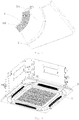
Fig. 8 , a patio type air conditioner indoor unit includes the above-described air outlet panel. - Those skilled in the art may easily understand that, under the premise that there is no conflict, various preferred solutions as described above may be freely combined and superimposed.
- It should be understood that, the above-described embodiments are merely exemplary but not restrictive, and those skilled in the art may make various obvious or equivalent modifications or replacements directed to the above-described details without departing from the basic principles of the present disclosure, which will be all included in the scope of the claims of the present disclosure.
Claims (14)
- An air outlet duct structure, comprising a first air duct wall (110) and a second air duct wall (210) arranged oppositely, wherein an air outlet passage (3) is formed between the first air duct wall (110) and the second air duct wall (210), the first air duct wall (110) comprises a plurality of concave curved surfaces connected along an airflow direction, and curvature radii of the plurality of concave curved surfaces decrease sequentially along the airflow direction.
- The air outlet duct structure according to claim 1, wherein the plurality of concave curved surfaces comprise a first concave curved surface (111) and a second concave curved surface (112), where a curvature radius of the first concave curved surface (111) is R1, and a curvature radius of the second concave curved surface (112) is R2, wherein a relationship between R1 and R2 is: R1=k1*R2, 1. 5≤k1≤2; and/or, 150mm≤R1≤250mm, 50mm≤R2≤150mm.
- The air outlet duct structure according to claim 2, wherein the second air duct wall (210) comprises a third concave curved surface (211) disposed proximate to an air outlet of the air outlet duct (3), and a curvature radius of the third concave curved surface (211) is R, wherein a relationship between R and R2 is : R=k2*R2, 3≤k2≤4; and/or, 150mm≤R≤550mm.
- An air outlet panel, comprising a panel body (1) and a corner cover plate (2) disposed at a corner of the panel body (1), wherein the corner cover plate (2) and the panel body (1) constitute the air outlet duct structure according to any one of claims 1 to 3, a part of a lateral surface of the panel body (1) constitutes the first air duct wall (110), and a part of a lateral surface of the corner cover plate (2) constitutes the second air duct wall (210), and a corner air outlet of the air outlet panel is formed between the corner cover plate (2) and the panel body (1).
- The air outlet panel according to claim 4, wherein
one end (21) of the corner cover plate (2) proximate to a center of the air outlet panel is closer to the center of the air outlet panel than one end (11) of the panel body (1) away from the center of the outlet panel; or,
in a direction from a center of the air outlet panel to an outer edge of the air outlet panel, one end (21) of the corner cover plate (2) proximate to the center of the air outlet panel is adjacent to one end (11) of the panel body (1) away from the center of the air outlet panel. - The air outlet panel according to claim 4, wherein the air outlet panel is an air outlet panel of a patio type indoor unit, and the lowest point of the corner cover plate (2) is higher than the lowest point of the panel body (1).
- The air outlet panel according to claim 4, wherein a flow guide structure (4) is provided between the corner cover plate (2) and the panel body (1).
- The air outlet panel according to claim 7, wherein in a direction from a center of the air outlet panel to an outer edge of the air outlet panel, the flow guide structure (4) partially overlaps with the panel body (1) and/or the corner cover plate (2); or,
in a direction from a center of the air outlet panel to an outer edge of the air outlet panel, one end (41) of the flow guide structure (4) proximate to the center of the air outlet panel is adjacent to one end (11) of the panel body (1) away from the center of the air outlet panel, and/or, one end (42) of the flow guide structure (4) away from the center of the air outlet panel is adjacent to one end (21) of the corner cover plate (2) proximate to the center of the air outlet panel. - The air outlet panel according to claim 8, wherein in the direction from the center of the air outlet panel to the outer edge of the air outlet panel, a size of an overlapping portion of the flow guide structure (4) and the panel body (1) is less than or equal to 2mm; and/or,
in the direction from the center of the air outlet panel to the outer edge of the air outlet panel, a size of an overlapping portion of the flow guide structure (4) and the corner cover plate (2) is less than or equal to 2mm. - The air outlet panel according to claim 7, wherein the flow guide structure (4) comprises one flow guide plate or a plurality of flow guide plates arranged along an airflow direction.
- The air outlet panel according to claim 10, wherein the flow guide plate is connected to the corner cover plate (2) through a connecting portion; and/or,
a raised structure (410) is provided on a leeward surface of the flow guide plate; and/or,
the air outlet panel is an air outlet panel of a patio type air conditioner indoor unit, and an included angle between the flow guide plate and a horizontal plane is greater than or equal to 0° and less than 90°. - The air outlet panel according to claim 11, wherein the raised structure (410) comprises a plurality of strip-like protrusions.
- The air outlet panel according to claim 12, wherein in a direction from a center of the air outlet panel to an outer edge of the air outlet panel, the plurality of strip-like protrusions are arranged at intervals from each other.
- A patio type air conditioner indoor unit, comprising the air outlet panel according to any one of claims 4 to 13.
Applications Claiming Priority (2)
| Application Number | Priority Date | Filing Date | Title |
|---|---|---|---|
| CN201811076214.1A CN110906521B (en) | 2018-09-14 | 2018-09-14 | An air outlet duct structure, an air outlet panel and a ceiling-type air conditioner indoor unit |
| PCT/CN2019/087353 WO2020052264A1 (en) | 2018-09-14 | 2019-05-17 | Air-out duct structure, air-out panel and ceiling air conditioner indoor unit |
Publications (3)
| Publication Number | Publication Date |
|---|---|
| EP3805657A1 true EP3805657A1 (en) | 2021-04-14 |
| EP3805657A4 EP3805657A4 (en) | 2021-08-18 |
| EP3805657B1 EP3805657B1 (en) | 2026-04-29 |
Family
ID=69776494
Family Applications (1)
| Application Number | Title | Priority Date | Filing Date |
|---|---|---|---|
| EP19860475.3A Active EP3805657B1 (en) | 2018-09-14 | 2019-05-17 | Air-out panel and ceiling air conditioner indoor unit |
Country Status (4)
| Country | Link |
|---|---|
| US (1) | US11988400B2 (en) |
| EP (1) | EP3805657B1 (en) |
| CN (1) | CN110906521B (en) |
| WO (1) | WO2020052264A1 (en) |
Families Citing this family (3)
| Publication number | Priority date | Publication date | Assignee | Title |
|---|---|---|---|---|
| CN110906521B (en) | 2018-09-14 | 2025-01-07 | 珠海格力电器股份有限公司 | An air outlet duct structure, an air outlet panel and a ceiling-type air conditioner indoor unit |
| WO2024065571A1 (en) * | 2022-09-30 | 2024-04-04 | 华为技术有限公司 | Air outlet, air outlet apparatus, air outlet device, and vehicle |
| CN119934569B (en) * | 2023-10-27 | 2025-11-21 | 宁波奥克斯电气有限公司 | A ceiling-mounted air outlet structure and ceiling-mounted air conditioner |
Family Cites Families (19)
| Publication number | Priority date | Publication date | Assignee | Title |
|---|---|---|---|---|
| JP2000009098A (en) * | 1998-06-22 | 2000-01-11 | Pacific Ind Co Ltd | Wall type bath room heating/drying apparatus |
| JP3408983B2 (en) | 1999-01-25 | 2003-05-19 | 三菱電機株式会社 | Ceiling-mounted air conditioner |
| JP3282616B2 (en) * | 1999-11-05 | 2002-05-20 | ダイキン工業株式会社 | Ceiling-mounted air conditioner |
| JP3820182B2 (en) * | 2002-05-10 | 2006-09-13 | 三菱重工業株式会社 | Air conditioner louver, airflow control structure for air conditioner, and air conditioner |
| CN2826236Y (en) | 2005-09-19 | 2006-10-11 | 乐金电子(天津)电器有限公司 | Air outlet structure of air conditioner for commercial use |
| JP2008009098A (en) | 2006-06-29 | 2008-01-17 | Namiki Precision Jewel Co Ltd | Optical connection device and mounting method |
| CN101206070B (en) | 2006-12-20 | 2011-08-31 | 乐金电子(天津)电器有限公司 | Front panel air outlet structure of ceiling embedding type air conditioner |
| CN101210713A (en) | 2006-12-30 | 2008-07-02 | 乐金电子(天津)电器有限公司 | Air outlet structure for embedded air-conditioner indoor set |
| CN102022781A (en) | 2010-12-08 | 2011-04-20 | 广东美的电器股份有限公司 | Split air-conditioner indoor unit |
| CN202835720U (en) | 2012-08-28 | 2013-03-27 | 广东美的制冷设备有限公司 | Air conditioner and embedded panel component thereof |
| WO2015035737A1 (en) * | 2013-09-16 | 2015-03-19 | 广东美的制冷设备有限公司 | Air conditioner having an adjustable-volume air output and a method for adjusting air output |
| CN104976744B (en) | 2014-04-14 | 2017-11-28 | 海尔集团公司 | Air conditioner indoor machine air duct structure |
| CN204388229U (en) | 2014-12-23 | 2015-06-10 | 广东美的制冷设备有限公司 | Embedded air-conditioner |
| PL3270074T3 (en) | 2015-03-26 | 2021-05-04 | Fujitsu General Limited | Ceiling-embedded air conditioner |
| CN206094454U (en) * | 2016-09-22 | 2017-04-12 | Tcl空调器(中山)有限公司 | Wind channel structure and air conditioner of air conditioner |
| CN106678982B (en) * | 2017-02-16 | 2022-07-29 | 珠海格力电器股份有限公司 | Air outlet panel and air conditioner with same |
| CN107044683B (en) | 2017-03-29 | 2023-06-30 | 珠海格力电器股份有限公司 | Air conditioner |
| CN209147382U (en) * | 2018-09-14 | 2019-07-23 | 珠海格力电器股份有限公司 | Air outlet duct structure, air outlet panel and courtyard type air conditioner indoor unit |
| CN110906521B (en) | 2018-09-14 | 2025-01-07 | 珠海格力电器股份有限公司 | An air outlet duct structure, an air outlet panel and a ceiling-type air conditioner indoor unit |
-
2018
- 2018-09-14 CN CN201811076214.1A patent/CN110906521B/en active Active
-
2019
- 2019-05-17 WO PCT/CN2019/087353 patent/WO2020052264A1/en not_active Ceased
- 2019-05-17 EP EP19860475.3A patent/EP3805657B1/en active Active
- 2019-05-17 US US17/258,858 patent/US11988400B2/en active Active
Also Published As
| Publication number | Publication date |
|---|---|
| CN110906521B (en) | 2025-01-07 |
| EP3805657A4 (en) | 2021-08-18 |
| WO2020052264A1 (en) | 2020-03-19 |
| CN110906521A (en) | 2020-03-24 |
| US20210285660A1 (en) | 2021-09-16 |
| US11988400B2 (en) | 2024-05-21 |
| EP3805657B1 (en) | 2026-04-29 |
Similar Documents
| Publication | Publication Date | Title |
|---|---|---|
| US10429088B2 (en) | Air-conditioning-apparatus indoor unit | |
| US11988400B2 (en) | Air-outlet duct structure, air-outlet panel and patio type air conditioner indoor unit | |
| US9995504B2 (en) | Air conditioner having air outlet louver with varying curvature | |
| US11022327B2 (en) | Outdoor unit of air-conditioning apparatus | |
| CN105509280A (en) | Air rectification device and air conditioner | |
| CN104180490A (en) | Wind-guiding reposition of redundant personnel mechanism | |
| CN104266271A (en) | Air conditioner | |
| CN108917007B (en) | Air guide structure and air conditioner with same | |
| CN209147382U (en) | Air outlet duct structure, air outlet panel and courtyard type air conditioner indoor unit | |
| EP3130860B1 (en) | Air conditioner | |
| CN108006817A (en) | Air conditioner | |
| CN204141724U (en) | Air conditioner | |
| CN110425717A (en) | A kind of canopy class building collides " one for more " tuyere device of pipe inspection for BIM | |
| WO2017049447A1 (en) | Mixed air output indoor unit of air conditioner | |
| CN210802179U (en) | Heat exchange plate and heat exchanger comprising same | |
| CN205825232U (en) | Indoor apparatus of air conditioner and air-conditioner | |
| CN213778127U (en) | Flow guide device, air conditioner indoor unit, air conditioner outdoor unit and air conditioner | |
| CN107940582A (en) | Air port structure and ceiling type air conditioner | |
| EP3640548B1 (en) | Air conditioner | |
| JP7280063B2 (en) | Blowout box device | |
| CN206724309U (en) | Air conditioner and its air outlet structure | |
| EP3015775A1 (en) | Indoor unit for air-conditioning device | |
| CN107490066B (en) | Indoor unit and air conditioning system | |
| US11573014B2 (en) | Air conditioner | |
| US10619853B2 (en) | Micro turbine generator with guide vane structure |
Legal Events
| Date | Code | Title | Description |
|---|---|---|---|
| STAA | Information on the status of an ep patent application or granted ep patent |
Free format text: STATUS: THE INTERNATIONAL PUBLICATION HAS BEEN MADE |
|
| PUAI | Public reference made under article 153(3) epc to a published international application that has entered the european phase |
Free format text: ORIGINAL CODE: 0009012 |
|
| STAA | Information on the status of an ep patent application or granted ep patent |
Free format text: STATUS: REQUEST FOR EXAMINATION WAS MADE |
|
| 17P | Request for examination filed |
Effective date: 20210108 |
|
| AK | Designated contracting states |
Kind code of ref document: A1 Designated state(s): AL AT BE BG CH CY CZ DE DK EE ES FI FR GB GR HR HU IE IS IT LI LT LU LV MC MK MT NL NO PL PT RO RS SE SI SK SM TR |
|
| AX | Request for extension of the european patent |
Extension state: BA ME |
|
| A4 | Supplementary search report drawn up and despatched |
Effective date: 20210721 |
|
| RIC1 | Information provided on ipc code assigned before grant |
Ipc: F24F 13/06 20060101AFI20210715BHEP Ipc: F24F 13/20 20060101ALI20210715BHEP Ipc: F24F 1/0011 20190101ALI20210715BHEP Ipc: F24F 1/0014 20190101ALI20210715BHEP |
|
| DAV | Request for validation of the european patent (deleted) | ||
| DAX | Request for extension of the european patent (deleted) | ||
| STAA | Information on the status of an ep patent application or granted ep patent |
Free format text: STATUS: EXAMINATION IS IN PROGRESS |
|
| 17Q | First examination report despatched |
Effective date: 20230124 |
|
| P01 | Opt-out of the competence of the unified patent court (upc) registered |
Effective date: 20230530 |
|
| REG | Reference to a national code |
Ref country code: DE Ref legal event code: R079 Free format text: PREVIOUS MAIN CLASS: F24F0013060000 Ipc: F24F0001001100 Ref document number: 602019084331 Country of ref document: DE |
|
| GRAP | Despatch of communication of intention to grant a patent |
Free format text: ORIGINAL CODE: EPIDOSNIGR1 |
|
| STAA | Information on the status of an ep patent application or granted ep patent |
Free format text: STATUS: GRANT OF PATENT IS INTENDED |
|
| RIC1 | Information provided on ipc code assigned before grant |
Ipc: F24F 1/0011 20190101AFI20250626BHEP Ipc: F24F 1/0014 20190101ALI20250626BHEP Ipc: F24F 1/0047 20190101ALI20250626BHEP Ipc: F24F 13/08 20060101ALI20250626BHEP Ipc: F24F 13/20 20060101ALI20250626BHEP Ipc: F24F 13/06 20060101ALI20250626BHEP |
|
| INTG | Intention to grant announced |
Effective date: 20250724 |
|
| GRAJ | Information related to disapproval of communication of intention to grant by the applicant or resumption of examination proceedings by the epo deleted |
Free format text: ORIGINAL CODE: EPIDOSDIGR1 |
|
| STAA | Information on the status of an ep patent application or granted ep patent |
Free format text: STATUS: EXAMINATION IS IN PROGRESS |
|
| INTC | Intention to grant announced (deleted) | ||
| GRAP | Despatch of communication of intention to grant a patent |
Free format text: ORIGINAL CODE: EPIDOSNIGR1 |
|
| STAA | Information on the status of an ep patent application or granted ep patent |
Free format text: STATUS: GRANT OF PATENT IS INTENDED |
|
| INTG | Intention to grant announced |
Effective date: 20260120 |
|
| GRAS | Grant fee paid |
Free format text: ORIGINAL CODE: EPIDOSNIGR3 |
|
| GRAA | (expected) grant |
Free format text: ORIGINAL CODE: 0009210 |
|
| STAA | Information on the status of an ep patent application or granted ep patent |
Free format text: STATUS: THE PATENT HAS BEEN GRANTED |
|
| AK | Designated contracting states |
Kind code of ref document: B1 Designated state(s): AL AT BE BG CH CY CZ DE DK EE ES FI FR GB GR HR HU IE IS IT LI LT LU LV MC MK MT NL NO PL PT RO RS SE SI SK SM TR |
|
| REG | Reference to a national code |
Ref country code: CH Ref legal event code: F10 Free format text: ST27 STATUS EVENT CODE: U-0-0-F10-F00 (AS PROVIDED BY THE NATIONAL OFFICE) Effective date: 20260429 Ref country code: GB Ref legal event code: FG4D |