EP3805588A1 - Heat shield grommet - Google Patents
Heat shield grommet Download PDFInfo
- Publication number
- EP3805588A1 EP3805588A1 EP19213779.2A EP19213779A EP3805588A1 EP 3805588 A1 EP3805588 A1 EP 3805588A1 EP 19213779 A EP19213779 A EP 19213779A EP 3805588 A1 EP3805588 A1 EP 3805588A1
- Authority
- EP
- European Patent Office
- Prior art keywords
- grommet
- radially inward
- radially
- radially outward
- inward
- Prior art date
- Legal status (The legal status is an assumption and is not a legal conclusion. Google has not performed a legal analysis and makes no representation as to the accuracy of the status listed.)
- Granted
Links
Images


Classifications
-
- F—MECHANICAL ENGINEERING; LIGHTING; HEATING; WEAPONS; BLASTING
- F16—ENGINEERING ELEMENTS AND UNITS; GENERAL MEASURES FOR PRODUCING AND MAINTAINING EFFECTIVE FUNCTIONING OF MACHINES OR INSTALLATIONS; THERMAL INSULATION IN GENERAL
- F16D—COUPLINGS FOR TRANSMITTING ROTATION; CLUTCHES; BRAKES
- F16D55/00—Brakes with substantially-radial braking surfaces pressed together in axial direction, e.g. disc brakes
- F16D55/24—Brakes with substantially-radial braking surfaces pressed together in axial direction, e.g. disc brakes with a plurality of axially-movable discs, lamellae, or pads, pressed from one side towards an axially-located member
- F16D55/26—Brakes with substantially-radial braking surfaces pressed together in axial direction, e.g. disc brakes with a plurality of axially-movable discs, lamellae, or pads, pressed from one side towards an axially-located member without self-tightening action
- F16D55/36—Brakes with a plurality of rotating discs all lying side by side
-
- F—MECHANICAL ENGINEERING; LIGHTING; HEATING; WEAPONS; BLASTING
- F16—ENGINEERING ELEMENTS AND UNITS; GENERAL MEASURES FOR PRODUCING AND MAINTAINING EFFECTIVE FUNCTIONING OF MACHINES OR INSTALLATIONS; THERMAL INSULATION IN GENERAL
- F16D—COUPLINGS FOR TRANSMITTING ROTATION; CLUTCHES; BRAKES
- F16D65/00—Parts or details
- F16D65/78—Features relating to cooling
-
- B—PERFORMING OPERATIONS; TRANSPORTING
- B64—AIRCRAFT; AVIATION; COSMONAUTICS
- B64C—AEROPLANES; HELICOPTERS
- B64C25/00—Alighting gear
- B64C25/32—Alighting gear characterised by elements which contact the ground or similar surface
- B64C25/34—Alighting gear characterised by elements which contact the ground or similar surface wheeled type, e.g. multi-wheeled bogies
-
- B—PERFORMING OPERATIONS; TRANSPORTING
- B64—AIRCRAFT; AVIATION; COSMONAUTICS
- B64C—AEROPLANES; HELICOPTERS
- B64C25/00—Alighting gear
- B64C25/32—Alighting gear characterised by elements which contact the ground or similar surface
- B64C25/42—Arrangement or adaptation of brakes
-
- F—MECHANICAL ENGINEERING; LIGHTING; HEATING; WEAPONS; BLASTING
- F16—ENGINEERING ELEMENTS AND UNITS; GENERAL MEASURES FOR PRODUCING AND MAINTAINING EFFECTIVE FUNCTIONING OF MACHINES OR INSTALLATIONS; THERMAL INSULATION IN GENERAL
- F16D—COUPLINGS FOR TRANSMITTING ROTATION; CLUTCHES; BRAKES
- F16D55/00—Brakes with substantially-radial braking surfaces pressed together in axial direction, e.g. disc brakes
- F16D2055/0004—Parts or details of disc brakes
- F16D2055/0058—Fully lined, i.e. braking surface extending over the entire disc circumference
-
- F—MECHANICAL ENGINEERING; LIGHTING; HEATING; WEAPONS; BLASTING
- F16—ENGINEERING ELEMENTS AND UNITS; GENERAL MEASURES FOR PRODUCING AND MAINTAINING EFFECTIVE FUNCTIONING OF MACHINES OR INSTALLATIONS; THERMAL INSULATION IN GENERAL
- F16D—COUPLINGS FOR TRANSMITTING ROTATION; CLUTCHES; BRAKES
- F16D65/00—Parts or details
- F16D65/78—Features relating to cooling
- F16D2065/785—Heat insulation or reflection
Definitions
- the present disclosure relates to wheel assemblies, and more specifically, to a heat shield grommet for an aircraft wheel assembly.
- Aircraft wheel and brake assemblies typically include a heat shield located between the friction disks of the heat sink and the radially inward surface of the wheel.
- Heat shields having a split ring structure, are generally not fastened directly to the wheel and may move radially and/or circumferentially. Movement of the heat shield can lead to wear on the heat shield and/or on components of the wheel (e.g., the fuse plug lug). Wear may also be caused by a reduction in the heat shield diameter during installation.
- a heat shield, with a split ring structure may be compressed to reduce the diameter of the heat shield and allow the heat shield to pass by radially inward wheel components (e.g., torque bar lugs), so the heat shield can be positioned radially inward of the wheel. Once in position, the heat shield should expand to its original diameter. If the heat shield does not expand to its intended diameter, it may contact the rotor lugs of the heat sink, which can lead to damage and corrosion of the heat shield and/or rotor lugs.
- the grommet may comprise a radially outward surface and a first radially inward surface opposite the radially outward surface.
- a plug opening may be formed in the radially outward surface.
- An exterior radial surface may extend from the radially outward surface to the first radially inward surface.
- a shield groove may be formed in the exterior radial surface.
- a first inward protrusion may extend radially inward from the first radially inward surface.
- a first slanted surface may extend from the radially outward surface to a first recessed surface of the grommet.
- the first recessed surface may be located radially inward of the radially outward surface.
- a second slanted surface may extend from the radially outward surface to a second recessed surface of the grommet. The second recessed surface may be located radially inward of the radially outward surface.
- a first interior radial surface may extend between the first recessed surface and the first radially inward surface.
- a second interior radial surface may extend between the second recessed surface and the first radially inward surface.
- a distance between the first slanted surface and the second slanted surface at the radially outward surface may be greater than a distance between the first interior radial surface and the second interior radial surface.
- a second inward protrusion may extend radially inward from the first radially inward surface.
- a first internal surface may extend from a second radially inward surface of the first inward protrusion to the radially outward surface.
- a second internal surface may extend from a third radially inward surface of the second inward protrusion to the radially outward surface.
- a distance between the first internal surface and the second internal surface at the radially outward surface may be greater than a distance between the first internal surface and the second internal surface at the first radially inward surface.
- the grommet may comprise silicon rubber.
- the heat shield may comprise a first shell and a grommet.
- An edge of the first shell may define, at least, a portion of a shield opening.
- the grommet may be located in the shield opening.
- the edge of the first shell may be located in a shield groove defined by the grommet.
- the grommet may comprise a radially outward surface, a first radially inward surface opposite the radially outward surface, a plug opening formed in the radially outward surface, an exterior radial surface extending from the radially outward surface to the first radially inward surface, and a first inward protrusion extending radially inward from the first radially inward surface.
- the exterior radial surface may define the shield groove.
- a second shell may be coupled to the first shell.
- the first shell and the second may define an internal volume of the heat shield.
- the grommet may further comprise a first slanted surface and a second slanted surface.
- the first slanted surface may extend from the radially outward surface to a first recessed surface of the grommet.
- the first recessed surface may be located radially inward of the radially outward surface.
- the second slanted surface may extend from the radially outward surface to a second recessed surface of the grommet.
- the second recessed surface may be located radially inward of the radially outward surface.
- the grommet may further comprise a first interior radial surface extending between the first recessed surface and the first radially inward surface, and a second interior radial surface extending between the second recessed surface and the first radially inward surface.
- a distance between the first slanted surface and the second slanted surface at the radially outward surface may be greater than a distance between the first interior radial surface and the second interior radial surface.
- the grommet may further comprise a second inward protrusion extending radially inward from the first radially inward surface.
- the grommet may further comprise a first internal surface extending from a second radially inward surface of the first inward protrusion to the radially outward surface, and a second internal surface extending from a third radially inward surface of the second inward protrusion to the radially outward surface.
- a distance between the first internal surface and the second internal surface at the radially outward surface may be greater than a distance between the first internal surface and the second internal surface at the first radially inward surface.
- the wheel assembly may comprise a wheel, a torque bar coupled to the wheel, and a heat shield located radially between the torque bar and the wheel.
- the heat shield may comprise a grommet.
- the grommet may be located in a shield opening defined by an edge of the heat shield.
- the edge of the heat shield may be located in a shield groove defined by the grommet.
- the wheel may comprise a fuse plug lug extending radially inward from a radially inward surface of the wheel.
- the fuse plug lug may be located in a plug opening formed in a radially outward surface of the grommet.
- the grommet may comprise an exterior radial surface extending from the radially outward surface of the grommet to a radially inward surface of the grommet.
- the exterior radial surface may define the shield groove.
- a first inward protrusion may extend radially inward from the radially inward surface of the grommet. The first inward protrusion may be located in a groove defined by the torque bar.
- the grommet may further comprise a first recessed surface and a second recessed surface.
- the first recessed surface may be located radially between a radially inward surface of the fuse plug lug and a first sidewall of the torque bar.
- the second recessed surface may be located radially between the radially inward surface of the fuse plug lug and a second sidewall of the torque bar.
- the first recessed surface of the grommet may contact the radially inward surface of the fuse plug lug, and the radially inward surface of the grommet may contact the first sidewall of the torque bar.
- the grommet may further comprise a first slanted surface and a second slanted surface.
- the first slanted surface may extend from the radially outward surface of the grommet to the first recessed surface.
- the second slanted surface may extend from the radially outward surface of the grommet to the second recessed surface.
- a first component that is "radially outward" of a second component means that the first component is positioned a greater distance away from a common axis of the first and second components as compared to the second component.
- a first component that is "radially inward" of a second component means that the first component is positioned closer to a common axis of the first and second components than the second component.
- Wheel and brake assembly 10 may include a wheel assembly 100 and a brake assembly 20.
- Wheel assembly 100 includes a wheel 102, which may include rims 16 for supporting a tire.
- Wheel 102 may be supported for rotation around an axle 12 by bearings 14. Stated differently, wheel 102 may spin (i.e., rotate) about an axis of rotation 111.
- axial refers to directions parallel to axis of rotation 111
- radial refers to directions perpendicular to axis of rotation 111
- circumumferential refers to directions about axis of rotation 111.
- Wheel assembly 100 includes a series of axially extending rotor splines 110 (one shown), also referred to as "torque bars”. Torque bars 110, in combination with brake assembly 20, may modulate rotation of wheel 102.
- Brake assembly 20 may include a piston housing 22, a torque tube 24, and a plurality of pistons 26 (one shown). Torque tube 24 may be an elongated annular structure that includes a reaction plate 34 and a series of axially extending stator splines 36 (one shown). Piston housing 22 may be mounted to axle 12. Torque tube 24 may be bolted, or otherwise attached, to piston housing 22 such that reaction plate 34 is located opposite pistons 26.
- Brake assembly 20 further includes a plurality of friction disks 38.
- the plurality of friction disks 38 may include a pressure plate 30, an end plate 32, non-rotatable friction disks (stators) 40, and rotatable friction disks (rotors) 42.
- End plate 32 may be connected to reaction plate 34.
- end plate 32 is non-rotatable by virtue of its connection to torque tube 24.
- Stators 40 and pressure plate 30 may include a plurality of stator lugs 44 at circumferentially spaced positions around an inner circumference of stators 40 and pressure plate 30.
- Rotors 42 may include a plurality of rotor lugs 46 at circumferentially spaced positions around an outer circumference of rotors 42.
- Stators 40 may engage stator splines 36 by locating stator splines 36 in gaps formed between stator lugs 44.
- stators 40 and pressure plate 30 are generally non-rotatable by virtue of their engagement with stator splines 36 on torque tube 24.
- rotors 42 engage torque bars 110 by locating torque bars 110 in gaps formed between rotor lugs 46.
- rotors 42 are rotatable by virtue of their engagement with torque bars 110 of wheel assembly 100.
- rotors 42 are arranged with end plate 32 on one end, pressure plate 30 on the other end, and stators 40 interleaved such that rotors 42 are adjacent to non-rotatable friction components.
- Pistons 26 are connected to piston housing 22 at circumferentially spaced positions around piston housing 22. Pistons 26 face axially toward friction disks 38 and contact a side of pressure plate 30 opposite rotors 42. Pistons 26 may be powered electrically, hydraulically, or pneumatically. In response to actuation of pistons 26, a force towards reaction plate 34 is exerted on friction disks 38 such that rotors 42 and stators 40 are pressed together between pressure plate 30 and end plate 32.
- wheel assembly 100 includes wheel 102 and torque bars 110.
- Torque bars 110 may be located circumferentially along a radially inward surface 112 of wheel 102.
- Torque bars 110 may be coupled to wheel 102.
- torque bars 110 may be coupled to wheel 102 via a fastener 114.
- Fastener 114 may comprise a bolt, screw, rivet, pin, clip, or any other suitable securement mechanism.
- Torque bars 110 may be oriented parallel to axis of rotation 111. Torque bars 110 are configured to engage brake assembly 20 in FIG. 1A .
- torque bars 110 may engage rotor lugs 46 of friction disks 38.
- Torque bar 110 includes a first end 130 and a second end 132. Torque bar 110 may define a fastener opening 134 proximate first end 130. A pin 136 of torque bar 110 is located at second end 132. Pin 136 may be configured to be received within a pin opening 138, with momentary reference to FIG. 2A , defined by wheel 102. A groove 140 may be formed in torque bar 110. Groove 140 may extend radially inward from a radially outward surface 141 of torque bar 110. Radially outward surface 141 may be oriented toward radially inward surface 112 of wheel 102, with momentary reference to FIG. 2A .
- torque bar 110 may include sidewall 142 and sidewall 144.
- Sidewall 142 may be generally on an opposite side of groove 140 as compared to the sidewall 144.
- Sidewalls 142, 144 may extend radially from a floor 146 of torque bar 110.
- Floor 146 may be oriented toward radially inward surface 112 of wheel 102 ( FIG. 2A ).
- Floor 146 and sidewalls 142, 144 may, at least partially, define groove 140.
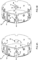
- wheel assembly 100 includes a heat shield 120.
- Heat shield 120 is located radially inward of wheel 102.
- Torque bars 110 may be located radially inward of heat shield 120.
- heat shield 120 may be located between torque bars 110 and radially inward surface 112 of wheel 102 and/or between radially inward surface 112 of wheel 102 and friction disks 38 of brake assembly 20 in FIG. 1A .
- Heat shield 120 may protect wheel 102 from heat generated by the friction disks 38.
- FIG. 2A illustrates a cross-section view of wheel assembly 100, taken along the line 2A-2A in FIG. 1B (i.e., axially through a torque bar 110).
- FIG. 2B illustrates a cross-section view of wheel assembly 100, taken along the line 2B-2B in FIG. 1B (i.e., circumferentially through a torque bar 110.
- FIG. 4A illustrates a perspective view of heat shield 120.
- heat shield 120 may include an outer (or first) shell 150 and an inner (or second) shell 152.
- Inner shell 152 may be located radially inward of outer shell 150.
- outer shell 150 may be spaced apart, in a radial direction, from inner shell 152.
- outer shell 150 and inner shell 152 may define an internal volume 153 of heat shield 120.
- Internal volume 153 may be devoid of material or may include thermally insulating material. While heat shield 120 is illustrated as including two shells (outer shell 150 and inner shell 152), it is further contemplated and understood that in various embodiments, heat shield 120 may comprise a single shell.
- one or more spacers 154 may be coupled to heat shield 120.
- Spacers 154 may extend radially outward from the outer circumferential surface of heat shield 120. Spacers 154 may contact radially inward surface 112 of wheel 102. Spacers 154 may maintain a preselected radial distance between heat shield 120 and radially inward surface 112 of wheel 102. In this regard, spacers 154 may prevent, or reduce occurrences of, heat shield 120 physically contacting wheel 102.
- shield openings 160 are formed through heat shield 120.
- An edge 162 of heat shield 120 may define a perimeter of shield openings 160.
- Edge 162 may be formed by inner shell 152 and/or outer shell 150.
- a portion of edge 162 may be formed by a combination of outer shell 150 and inner shell 152.
- outer shell 150 and inner shell 152 may be attached to one another along edge 162.
- the locations of shield openings 160 tend to correspond to fuse plug lugs 164 on wheel 102.
- Fuse plug lugs 164 may comprise protrusions that extend radially inward from radially inward surface 112 of wheel 102.
- Fuse plug lugs 164 may define a fuse plug orifice 166.
- Fuse plug orifice 166 may receive a tire fuse plug configured to release air from the tire.
- heat shield 120 of wheel assembly 100 may include one or more grommets 170.
- FIG. 4B shows grommet 170 coupled to heat shield 120.
- Grommets 170 may be located in shield openings 160 of heat shield 120.
- Grommets 170 may be formed from a thermally insulating material capable of withstanding temperatures of 500° F (260° C) and having a durometer hardness of 75 ⁇ 5, such as a thermoplastic elastomer.
- grommet 170 may be formed from silicone rubber, polyoxymethlene, polypropylene, polyvinyl chloride, polyethlene, or any other thermally insulating material
- grommets 170 are configured to receive fuse plug lug 164 of wheel 102. Grommets 170 may extend into groove 140 in torque bar 110. As described in further detail below, grommet 170 defines a shield groove 174 configured to receive edge 162 of heat shield 120.
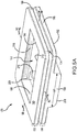
- grommet 170 defines a plug opening 172.
- Plug opening 172 is configured to receive fuse plug lug 164 of wheel 102.
- Grommet 170 defines a shield groove 174.
- Shield groove 174 is configured to receive edge 162 of heat shield 120.
- Grommet 170 includes a radially outward surface 180 and a (first) radially inward surface 182.
- Radially outward surface 180 which is generally opposite radially inward surface 182, is oriented away from axis of rotation 111.
- Plug opening 172 may be formed through radially outward surface 180 and radially inward surface 182.
- Shield groove 174 may be formed in an exterior radial surface 186 of grommet 170. Exterior radial surface 186 extends radially between radially outward surface 180 and radially inward surface 182.
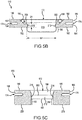
- FIGs. 5B and 5C illustrate cross-section views of grommet 170 taken along the line 5B-5B and the line 5C-5C, respectively, in FIG. 5A .
- grommet 170 further includes one or more inward protrusions, such as first inward protrusion 188 and second inward protrusion 190.
- First and second inward protrusions 188, 190 extend radially inward from radially inward surface 182 of grommet 170.
- First inward protrusion 188 may be on an opposite side of plug opening 172 as compared to second inward protrusion 190.
- First and second inward protrusions 188, 190 may each have a width W1.
- width W1 of first and second inward protrusions 188, 190 may be selected to such that first and second inward protrusions 188, 190 may be located in groove 140 of torque bar 110.
- the width W2 of groove 140 may be greater than width W1 of first and second inward protrusions 188, 190. Locating first and second inward protrusions 188, 190 within groove 140 tends to prevent, or restrict, circumferential movement of heat shield 120, thereby reducing wear on heat shield 120.
- Locating the first and second inward protrusions 188, 190 of circumferentially adjacent grommets 170 within various torque bars 110 along wheel 102 also tends to ensure, or increase a likelihood, that heat shield 120 is oriented at its desired diameter. Controlling the diameter of heat shield 120 tends to decrease occurrences of contact between heat shield 120 and rotor lugs 46 in FIG. 1A .
- shield groove 174 is configured to receive edge 162 of heat shield 120.
- an outer flange 192 of grommet 170 may be radially outward of edge 162 and an inner flange 194 of grommet 170 may be radially inward of edge 162 (i.e., edge 162 is located radially between inner flange 194 and outer flange 192).
- Outer flange 192 may be located between shield groove 174 and radially outward surface 180.
- Inner flange 194 may be located between shield groove 174 and radially inward surface 182.
- plug opening 172 of grommet 170 may be configured to receive fuse plug lug 164 of wheel 102. Locating fuse plug lug 164 within plug opening 172 tends to prevent or reduce axial and circumferential movement of heat shield 120.
- grommet 170 may include a first slanted surface 196 and a second slanted surface 198.
- First slanted surface 196 may extend from radially outward surface 180 of grommet 170 to a first recessed surface 200 of grommet 170.
- Second slanted surface 198 may extend from radially outward surface 180 of grommet 170 to a second recessed surface 202 of grommet 170.
- An angle theta ( ⁇ ) of first and second slanted surfaces 196, 198, relative to a plane parallel to radially outward surface 180, may be supplementary to the angle of fuse plug lug 164 relative to radially inward surface 112 of wheel 102.
- angle theta ( ⁇ ) may be between 90° and 20°. In various embodiments, angle theta ( ⁇ ) may be between 60° and 30°.
- First and second recessed surfaces 200, 202 may be oriented in the radially outward direction. First and second recessed surfaces 200, 202 may be recessed radially with respect to radially outward surface 180. In this regard, first and second recessed surfaces 200, 202 are located radially inward of radially outward surface 180 and radially outward of radially inward surface 182. In various embodiments, a first interior radial surface 210 may extend between first recessed surface 200 and radially inward surface 182.
- a second interior radial surface 212 may extend between second recessed surface 202 and radially inward surface 182. In various embodiments, a distance between first slanted surface 196 and second slanted surface 198, as measured at the radially outward surface 180 may be greater than a distance between first interior radial surface 210 and second interior radial surface 212.
- First and second slanted surfaces 196, 198, first and second recessed surfaces 200, 202, and first and second interior radial surfaces 210, 212 may each extend from a first internal surface 214 of grommet 170 to a second internal surface 216 of grommet 170. Stated differently, first and second internal surfaces 214, 216 may each extend between first and second slanted surfaces 196, 198; first and second recessed surfaces 200, 202; and first and second interior radial surfaces 210, 212. First internal surface 214 is oriented generally toward second internal surface 216. First internal surface 214 may extend between a (second) radially inward surface 218 of first inward protrusion 188 and radially outward surface 180.
- Second internal surface 216 may extend between a (third) radially inward surface 220 of second inward protrusion 190 and radially outward surface 180.
- First and second internal surfaces 214, 216 may extend in the radial direction and/or may be generally orthogonal to radially outward surface 180.
- "generally" means ⁇ 5°.
- a radially outward portion of first and second internal surfaces 214, 216 may be slanted (i.e., oriented at a non-orthogonal angle relative to radially outward surface 180).
- a distance between first internal surface 214 and second internal surface 216 as measured at radially outward surface 180 may be greater than the distance between first internal surface 214 and second internal surface 216 as measured at radially inward surface 182.
- First and second recessed surfaces 200, 202 may contact a radially inward surface 204 of fuse plug lug 164 and/or radially inward surface 182 may contact radially outward surface 141 ( FIG. 3 ) of torque bar 110.
- first recessed surface 200 may be located between sidewall 144 of torque bar 110 and radially inward surface 204 of fuse plug lug 164
- second recessed surface 202 may be located between sidewall 142 to torque bar 110 and radially inward surface 204 of fuse plug lug 164.
- a distance D1 between radially inward surface 182 and first recessed surface 200 may be selected to be approximately equal to the distance between radially inward surface 204 of fuse plug lug 164 and radially outward surface 141 of sidewall 144 of torque bar 110.
- “approximately” means ⁇ 0.02 inches (0.51 mm).
- a distance between radially inward surface 182 and second recessed surface 202, which may be equal to distance D1 may be selected to be approximately equal to the distance between radially inward surface 204 of fuse plug lug 164 and radially outward surface 141 of sidewall 142 of torque bar 110.
- “approximately” means ⁇ 0.02 inches (0.51 mm).
- Locating a portion of grommet 170 between and/or in contact with radially inward surface 204 of fuse plug lug 164 and radially inward surface 141 of torque bar 110 tends to prevent, or restrict, radial movement of heat shield 120, which is located in shield groove 174. Restricting radial movement of heat shield 120 decreases a likelihood heat shield 120 will contact radially inward surface 112 of wheel 102 and/or rotor lugs 46 of friction disks 38.
- any of the method or process descriptions may be executed in any order and are not necessarily limited to the order presented.
- any reference to singular includes plural embodiments, and any reference to more than one component or step may include a singular embodiment or step.
- Elements and steps in the figures are illustrated for simplicity and clarity and have not necessarily been rendered according to any particular sequence. For example, steps that may be performed concurrently or in different order are illustrated in the figures to help to improve understanding of embodiments of the present disclosure.
- Any reference to attached, fixed, connected or the like may include permanent, removable, temporary, partial, full and/or any other possible attachment option. Additionally, any reference to without contact (or similar phrases) may also include reduced contact or minimal contact. Surface shading lines may be used throughout the figures to denote different parts or areas but not necessarily to denote the same or different materials. In some cases, reference coordinates may be specific to each figure.
- references to "one embodiment”, “an embodiment”, “various embodiments”, etc. indicate that the embodiment described may include a particular feature, structure, or characteristic, but every embodiment may not necessarily include the particular feature, structure, or characteristic. Moreover, such phrases are not necessarily referring to the same embodiment. Further, when a particular feature, structure, or characteristic is described in connection with an embodiment, it is submitted that it is within the knowledge of one skilled in the art to affect such feature, structure, or characteristic in connection with other embodiments whether or not explicitly described. After reading the description, it will be apparent to one skilled in the relevant art(s) how to implement the disclosure in alternative embodiments.
Landscapes
- Engineering & Computer Science (AREA)
- General Engineering & Computer Science (AREA)
- Mechanical Engineering (AREA)
- Braking Arrangements (AREA)
Abstract
Description
- The present disclosure relates to wheel assemblies, and more specifically, to a heat shield grommet for an aircraft wheel assembly.
- Aircraft wheel and brake assemblies typically include a heat shield located between the friction disks of the heat sink and the radially inward surface of the wheel. Heat shields, having a split ring structure, are generally not fastened directly to the wheel and may move radially and/or circumferentially. Movement of the heat shield can lead to wear on the heat shield and/or on components of the wheel (e.g., the fuse plug lug). Wear may also be caused by a reduction in the heat shield diameter during installation. For example, a heat shield, with a split ring structure, may be compressed to reduce the diameter of the heat shield and allow the heat shield to pass by radially inward wheel components (e.g., torque bar lugs), so the heat shield can be positioned radially inward of the wheel. Once in position, the heat shield should expand to its original diameter. If the heat shield does not expand to its intended diameter, it may contact the rotor lugs of the heat sink, which can lead to damage and corrosion of the heat shield and/or rotor lugs.
- The present disclosure provides a grommet for a heat shield. In accordance with various embodiments, the grommet may comprise a radially outward surface and a first radially inward surface opposite the radially outward surface. A plug opening may be formed in the radially outward surface. An exterior radial surface may extend from the radially outward surface to the first radially inward surface. A shield groove may be formed in the exterior radial surface. A first inward protrusion may extend radially inward from the first radially inward surface.
- In various embodiments, a first slanted surface may extend from the radially outward surface to a first recessed surface of the grommet. The first recessed surface may be located radially inward of the radially outward surface. A second slanted surface may extend from the radially outward surface to a second recessed surface of the grommet. The second recessed surface may be located radially inward of the radially outward surface.
- In various embodiments, a first interior radial surface may extend between the first recessed surface and the first radially inward surface. A second interior radial surface may extend between the second recessed surface and the first radially inward surface. A distance between the first slanted surface and the second slanted surface at the radially outward surface may be greater than a distance between the first interior radial surface and the second interior radial surface.
- In various embodiments, a second inward protrusion may extend radially inward from the first radially inward surface. In accordance with various embodiments, a first internal surface may extend from a second radially inward surface of the first inward protrusion to the radially outward surface. A second internal surface may extend from a third radially inward surface of the second inward protrusion to the radially outward surface.
- In various embodiments, a distance between the first internal surface and the second internal surface at the radially outward surface may be greater than a distance between the first internal surface and the second internal surface at the first radially inward surface. In various embodiments, the grommet may comprise silicon rubber.
- A heat shield is also disclosed herein. In accordance with various embodiments, the heat shield may comprise a first shell and a grommet. An edge of the first shell may define, at least, a portion of a shield opening. The grommet may be located in the shield opening. The edge of the first shell may be located in a shield groove defined by the grommet.
- In various embodiments, the grommet may comprise a radially outward surface, a first radially inward surface opposite the radially outward surface, a plug opening formed in the radially outward surface, an exterior radial surface extending from the radially outward surface to the first radially inward surface, and a first inward protrusion extending radially inward from the first radially inward surface. The exterior radial surface may define the shield groove.
- In various embodiments, a second shell may be coupled to the first shell. The first shell and the second may define an internal volume of the heat shield.
- In various embodiments, the grommet may further comprise a first slanted surface and a second slanted surface. The first slanted surface may extend from the radially outward surface to a first recessed surface of the grommet. The first recessed surface may be located radially inward of the radially outward surface. The second slanted surface may extend from the radially outward surface to a second recessed surface of the grommet. The second recessed surface may be located radially inward of the radially outward surface.
- In various embodiments, the grommet may further comprise a first interior radial surface extending between the first recessed surface and the first radially inward surface, and a second interior radial surface extending between the second recessed surface and the first radially inward surface. A distance between the first slanted surface and the second slanted surface at the radially outward surface may be greater than a distance between the first interior radial surface and the second interior radial surface.
- In various embodiments, the grommet may further comprise a second inward protrusion extending radially inward from the first radially inward surface. In various embodiments, the grommet may further comprise a first internal surface extending from a second radially inward surface of the first inward protrusion to the radially outward surface, and a second internal surface extending from a third radially inward surface of the second inward protrusion to the radially outward surface. A distance between the first internal surface and the second internal surface at the radially outward surface may be greater than a distance between the first internal surface and the second internal surface at the first radially inward surface.
- A wheel assembly is also disclosed herein. In accordance with various embodiments, the wheel assembly may comprise a wheel, a torque bar coupled to the wheel, and a heat shield located radially between the torque bar and the wheel. The heat shield may comprise a grommet. The grommet may be located in a shield opening defined by an edge of the heat shield. The edge of the heat shield may be located in a shield groove defined by the grommet.
- In various embodiments, the wheel may comprise a fuse plug lug extending radially inward from a radially inward surface of the wheel. The fuse plug lug may be located in a plug opening formed in a radially outward surface of the grommet.
- In various embodiments, the grommet may comprise an exterior radial surface extending from the radially outward surface of the grommet to a radially inward surface of the grommet. The exterior radial surface may define the shield groove. A first inward protrusion may extend radially inward from the radially inward surface of the grommet. The first inward protrusion may be located in a groove defined by the torque bar.
- In various embodiments, the grommet may further comprise a first recessed surface and a second recessed surface. The first recessed surface may be located radially between a radially inward surface of the fuse plug lug and a first sidewall of the torque bar. The second recessed surface may be located radially between the radially inward surface of the fuse plug lug and a second sidewall of the torque bar.
- In various embodiments, the first recessed surface of the grommet may contact the radially inward surface of the fuse plug lug, and the radially inward surface of the grommet may contact the first sidewall of the torque bar.
- In various embodiments, the grommet may further comprise a first slanted surface and a second slanted surface. The first slanted surface may extend from the radially outward surface of the grommet to the first recessed surface. The second slanted surface may extend from the radially outward surface of the grommet to the second recessed surface.
- The foregoing features and elements may be combined in various combinations without exclusivity, unless expressly indicated herein otherwise. These features and elements as well as the operation of the disclosed embodiments will become more apparent in light of the following description and accompanying drawings.
-
-
FIG. 1A illustrates a wheel and brake assembly, in accordance with various embodiments; -
FIG. 1B illustrates a perspective view of a wheel assembly, in accordance with various embodiments; -
FIGs. 2A and2B illustrate cross-section views of a wheel assembly taken along theline 2A-2A and theline 2B-2B, respectively, inFIG. 1B , in accordance with various embodiments; -
FIG. 3 illustrates a perspective view of a torque bar, in accordance with various embodiments; -
FIG. 4A illustrates a perspective view a heat shield, in accordance with various embodiments; -
FIG. 4B illustrates a perspective view a heat shield with grommets located in the heat shield openings, in accordance with various embodiments; -
FIG. 5A illustrates a perspective view of a grommet for a heat shield, in accordance with various embodiments; and -
FIGs. 5B and 5C illustrate cross-section views of a grommet for a heat shield taken along theline 5B-5B and theline 5C-5C, respectively, inFIG. 5A , in accordance with various embodiments. - The subject matter of the present disclosure is particularly pointed out and distinctly claimed in the concluding portion of the specification. A more complete understanding of the present disclosure, however, may best be obtained by referring to the detailed description and claims when considered in connection with the drawing figures, wherein like numerals denote like elements.
- The detailed description of exemplary embodiments herein makes reference to the accompanying drawings, which show exemplary embodiments by way of illustration. While these exemplary embodiments are described in sufficient detail to enable those skilled in the art to practice the exemplary embodiments of the disclosure, it should be understood that other embodiments may be realized and that logical changes and adaptations in design and construction may be made in accordance with this disclosure and the teachings herein without departing from the spirit and scope of the disclosure. Thus, the detailed description herein is presented for purposes of illustration only and not of limitation.
- Surface shading and cross hatching may be used throughout the figures to denote different parts but not necessarily to denote the same or different materials. Throughout the present disclosure, like reference numbers denote like elements. Accordingly, elements with like element numbering may be shown in the figures, but may not necessarily be repeated herein for the sake of clarity.
- A first component that is "radially outward" of a second component means that the first component is positioned a greater distance away from a common axis of the first and second components as compared to the second component. A first component that is "radially inward" of a second component means that the first component is positioned closer to a common axis of the first and second components than the second component.
- Referring to
FIG. 1A , a wheel andbrake assembly 10 is illustrated, in accordance with various embodiments. Wheel andbrake assembly 10 may include awheel assembly 100 and abrake assembly 20.Wheel assembly 100 includes awheel 102, which may includerims 16 for supporting a tire.Wheel 102 may be supported for rotation around anaxle 12 bybearings 14. Stated differently,wheel 102 may spin (i.e., rotate) about an axis ofrotation 111. As used herein, the term "axial" refers to directions parallel to axis ofrotation 111, the term "radial" refers to directions perpendicular to axis ofrotation 111, and the term "circumferential" refers to directions about axis ofrotation 111. -
Wheel assembly 100 includes a series of axially extending rotor splines 110 (one shown), also referred to as "torque bars". Torque bars 110, in combination withbrake assembly 20, may modulate rotation ofwheel 102.Brake assembly 20 may include apiston housing 22, atorque tube 24, and a plurality of pistons 26 (one shown).Torque tube 24 may be an elongated annular structure that includes areaction plate 34 and a series of axially extending stator splines 36 (one shown).Piston housing 22 may be mounted toaxle 12.Torque tube 24 may be bolted, or otherwise attached, topiston housing 22 such thatreaction plate 34 is locatedopposite pistons 26. -
Brake assembly 20 further includes a plurality offriction disks 38. The plurality offriction disks 38 may include apressure plate 30, anend plate 32, non-rotatable friction disks (stators) 40, and rotatable friction disks (rotors) 42.End plate 32 may be connected toreaction plate 34. In this regard,end plate 32 is non-rotatable by virtue of its connection totorque tube 24. Stators 40 andpressure plate 30 may include a plurality of stator lugs 44 at circumferentially spaced positions around an inner circumference ofstators 40 andpressure plate 30.Rotors 42 may include a plurality of rotor lugs 46 at circumferentially spaced positions around an outer circumference ofrotors 42. -
Stators 40 may engagestator splines 36 by locatingstator splines 36 in gaps formed between stator lugs 44. Thus,stators 40 andpressure plate 30 are generally non-rotatable by virtue of their engagement withstator splines 36 ontorque tube 24. Similarly,rotors 42 engagetorque bars 110 by locatingtorque bars 110 in gaps formed between rotor lugs 46. Thus,rotors 42 are rotatable by virtue of their engagement withtorque bars 110 ofwheel assembly 100. - In various embodiments,
rotors 42 are arranged withend plate 32 on one end,pressure plate 30 on the other end, andstators 40 interleaved such thatrotors 42 are adjacent to non-rotatable friction components.Pistons 26 are connected topiston housing 22 at circumferentially spaced positions aroundpiston housing 22.Pistons 26 face axially towardfriction disks 38 and contact a side ofpressure plate 30 oppositerotors 42.Pistons 26 may be powered electrically, hydraulically, or pneumatically. In response to actuation ofpistons 26, a force towardsreaction plate 34 is exerted onfriction disks 38 such thatrotors 42 andstators 40 are pressed together betweenpressure plate 30 andend plate 32. - With reference to
FIG. 1B , additional details ofwheel assembly 100 are illustrated. In accordance with various embodiments,wheel assembly 100 includeswheel 102 and torque bars 110. Torque bars 110 may be located circumferentially along a radiallyinward surface 112 ofwheel 102. - Torque bars 110 may be coupled to
wheel 102. For example, torque bars 110 may be coupled towheel 102 via afastener 114.Fastener 114 may comprise a bolt, screw, rivet, pin, clip, or any other suitable securement mechanism. Torque bars 110 may be oriented parallel to axis ofrotation 111. Torque bars 110 are configured to engagebrake assembly 20 inFIG. 1A . For example, torque bars 110 may engage rotor lugs 46 offriction disks 38. - With reference to
FIG. 3 , atorque bar 110 is illustrated, in accordance with various embodiments.Torque bar 110 includes afirst end 130 and asecond end 132.Torque bar 110 may define afastener opening 134 proximatefirst end 130. Apin 136 oftorque bar 110 is located atsecond end 132.Pin 136 may be configured to be received within apin opening 138, with momentary reference toFIG. 2A , defined bywheel 102. Agroove 140 may be formed intorque bar 110. Groove 140 may extend radially inward from a radiallyoutward surface 141 oftorque bar 110. Radiallyoutward surface 141 may be oriented toward radiallyinward surface 112 ofwheel 102, with momentary reference toFIG. 2A . In this regard,torque bar 110 may includesidewall 142 andsidewall 144.Sidewall 142 may be generally on an opposite side ofgroove 140 as compared to thesidewall 144.Sidewalls floor 146 oftorque bar 110.Floor 146 may be oriented toward radiallyinward surface 112 of wheel 102 (FIG. 2A ).Floor 146 andsidewalls groove 140. - Returning to
FIG. 1B , in accordance with various,wheel assembly 100 includes aheat shield 120.Heat shield 120 is located radially inward ofwheel 102. Torque bars 110 may be located radially inward ofheat shield 120. In this regard,heat shield 120 may be located betweentorque bars 110 and radiallyinward surface 112 ofwheel 102 and/or between radiallyinward surface 112 ofwheel 102 andfriction disks 38 ofbrake assembly 20 inFIG. 1A .Heat shield 120 may protectwheel 102 from heat generated by thefriction disks 38. -
FIG. 2A illustrates a cross-section view ofwheel assembly 100, taken along theline 2A-2A inFIG. 1B (i.e., axially through a torque bar 110).FIG. 2B illustrates a cross-section view ofwheel assembly 100, taken along theline 2B-2B inFIG. 1B (i.e., circumferentially through atorque bar 110.FIG. 4A illustrates a perspective view ofheat shield 120. With combined reference toFIG. 2A ,FIG. 2B , andFIG. 4A , in various embodiments,heat shield 120 may include an outer (or first)shell 150 and an inner (or second)shell 152.Inner shell 152 may be located radially inward ofouter shell 150. In various locations alongheat shield 120,outer shell 150 may be spaced apart, in a radial direction, frominner shell 152. In this regard,outer shell 150 andinner shell 152 may define aninternal volume 153 ofheat shield 120.Internal volume 153 may be devoid of material or may include thermally insulating material. Whileheat shield 120 is illustrated as including two shells (outer shell 150 and inner shell 152), it is further contemplated and understood that in various embodiments,heat shield 120 may comprise a single shell. - In various embodiments, one or
more spacers 154 may be coupled toheat shield 120.Spacers 154 may extend radially outward from the outer circumferential surface ofheat shield 120.Spacers 154 may contact radiallyinward surface 112 ofwheel 102.Spacers 154 may maintain a preselected radial distance betweenheat shield 120 and radiallyinward surface 112 ofwheel 102. In this regard,spacers 154 may prevent, or reduce occurrences of,heat shield 120 physically contactingwheel 102. - In accordance with various embodiments,
shield openings 160 are formed throughheat shield 120. Anedge 162 ofheat shield 120 may define a perimeter ofshield openings 160.Edge 162 may be formed byinner shell 152 and/orouter shell 150. In various embodiments, a portion ofedge 162 may be formed by a combination ofouter shell 150 andinner shell 152. For example,outer shell 150 andinner shell 152 may be attached to one another alongedge 162. The locations ofshield openings 160 tend to correspond to fuse plug lugs 164 onwheel 102. Fuse plug lugs 164 may comprise protrusions that extend radially inward from radiallyinward surface 112 ofwheel 102. Fuse plug lugs 164 may define afuse plug orifice 166.Fuse plug orifice 166 may receive a tire fuse plug configured to release air from the tire. - In accordance with various embodiments,
heat shield 120 ofwheel assembly 100 may include one ormore grommets 170.FIG. 4B showsgrommet 170 coupled toheat shield 120.Grommets 170 may be located inshield openings 160 ofheat shield 120.Grommets 170 may be formed from a thermally insulating material capable of withstanding temperatures of 500° F (260° C) and having a durometer hardness of 75 ± 5, such as a thermoplastic elastomer. In various embodiments,grommet 170 may be formed from silicone rubber, polyoxymethlene, polypropylene, polyvinyl chloride, polyethlene, or any other thermally insulating material - With reference to
FIG. 2A and2B ,grommets 170 are configured to receivefuse plug lug 164 ofwheel 102.Grommets 170 may extend intogroove 140 intorque bar 110. As described in further detail below,grommet 170 defines ashield groove 174 configured to receiveedge 162 ofheat shield 120. - With reference to
FIG. 5A , a perspective view of agrommet 170 is illustrated. In accordance with various embodiments,grommet 170 defines aplug opening 172.Plug opening 172 is configured to receivefuse plug lug 164 ofwheel 102.Grommet 170 defines ashield groove 174.Shield groove 174 is configured to receiveedge 162 ofheat shield 120. -
Grommet 170 includes a radiallyoutward surface 180 and a (first) radiallyinward surface 182. Radiallyoutward surface 180, which is generally opposite radiallyinward surface 182, is oriented away from axis ofrotation 111. Plug opening 172 may be formed through radiallyoutward surface 180 and radiallyinward surface 182.Shield groove 174 may be formed in an exteriorradial surface 186 ofgrommet 170. Exteriorradial surface 186 extends radially between radiallyoutward surface 180 and radiallyinward surface 182. -
FIGs. 5B and 5C illustrate cross-section views ofgrommet 170 taken along theline 5B-5B and theline 5C-5C, respectively, inFIG. 5A . With combined reference toFIGs. 5A ,5B, and 5C , in various embodiments,grommet 170 further includes one or more inward protrusions, such as firstinward protrusion 188 and secondinward protrusion 190. First and secondinward protrusions inward surface 182 ofgrommet 170. Firstinward protrusion 188 may be on an opposite side of plug opening 172 as compared to secondinward protrusion 190. First and secondinward protrusions FIGs. 2B and5B , width W1 of first and secondinward protrusions inward protrusions groove 140 oftorque bar 110. In this regard, the width W2 ofgroove 140, with momentary reference toFIG. 3 , may be greater than width W1 of first and secondinward protrusions inward protrusions groove 140 tends to prevent, or restrict, circumferential movement ofheat shield 120, thereby reducing wear onheat shield 120. Locating the first and secondinward protrusions adjacent grommets 170 withinvarious torque bars 110 alongwheel 102 also tends to ensure, or increase a likelihood, thatheat shield 120 is oriented at its desired diameter. Controlling the diameter ofheat shield 120 tends to decrease occurrences of contact betweenheat shield 120 and rotor lugs 46 inFIG. 1A . - With combined reference to
FIGs. 2A and2B andFIGs. 5B and 5C ,shield groove 174 is configured to receiveedge 162 ofheat shield 120. In this regard, anouter flange 192 ofgrommet 170 may be radially outward ofedge 162 and aninner flange 194 ofgrommet 170 may be radially inward of edge 162 (i.e.,edge 162 is located radially betweeninner flange 194 and outer flange 192).Outer flange 192 may be located betweenshield groove 174 and radiallyoutward surface 180.Inner flange 194 may be located betweenshield groove 174 and radiallyinward surface 182. - With combined reference to
FIG. 2B andFIG. 5B , plug opening 172 ofgrommet 170 may be configured to receivefuse plug lug 164 ofwheel 102. Locatingfuse plug lug 164 within plug opening 172 tends to prevent or reduce axial and circumferential movement ofheat shield 120. - In various embodiments,
grommet 170 may include a firstslanted surface 196 and a secondslanted surface 198. First slantedsurface 196 may extend from radially outward surface 180 ofgrommet 170 to a first recessedsurface 200 ofgrommet 170. Secondslanted surface 198 may extend from radially outward surface 180 ofgrommet 170 to a second recessedsurface 202 ofgrommet 170. An angle theta (θ) of first and secondslanted surfaces outward surface 180, may be supplementary to the angle offuse plug lug 164 relative to radiallyinward surface 112 ofwheel 102. In various embodiments, angle theta (θ) may be between 90° and 20°. In various embodiments, angle theta (θ) may be between 60° and 30°. First and second recessedsurfaces surfaces outward surface 180. In this regard, first and second recessedsurfaces outward surface 180 and radially outward of radiallyinward surface 182. In various embodiments, a first interiorradial surface 210 may extend between first recessedsurface 200 and radiallyinward surface 182. A second interiorradial surface 212 may extend between second recessedsurface 202 and radiallyinward surface 182. In various embodiments, a distance between firstslanted surface 196 and secondslanted surface 198, as measured at the radiallyoutward surface 180 may be greater than a distance between first interiorradial surface 210 and second interiorradial surface 212. - First and second
slanted surfaces surfaces internal surface 214 ofgrommet 170 to a secondinternal surface 216 ofgrommet 170. Stated differently, first and secondinternal surfaces slanted surfaces surfaces internal surface 214 is oriented generally toward secondinternal surface 216. Firstinternal surface 214 may extend between a (second) radiallyinward surface 218 of firstinward protrusion 188 and radiallyoutward surface 180. Secondinternal surface 216 may extend between a (third) radiallyinward surface 220 of secondinward protrusion 190 and radiallyoutward surface 180. First and secondinternal surfaces outward surface 180. As used in the previous context only, "generally" means ± 5°. In various embodiments, a radially outward portion of first and secondinternal surfaces internal surface 214 and secondinternal surface 216 as measured at radiallyoutward surface 180 may be greater than the distance between firstinternal surface 214 and secondinternal surface 216 as measured at radiallyinward surface 182. - First and second recessed
surfaces inward surface 204 offuse plug lug 164 and/or radiallyinward surface 182 may contact radially outward surface 141 (FIG. 3 ) oftorque bar 110. In this regard, first recessedsurface 200 may be located betweensidewall 144 oftorque bar 110 and radiallyinward surface 204 offuse plug lug 164, and second recessedsurface 202 may be located betweensidewall 142 totorque bar 110 and radiallyinward surface 204 offuse plug lug 164. A distance D1 between radiallyinward surface 182 and first recessedsurface 200 may be selected to be approximately equal to the distance between radiallyinward surface 204 offuse plug lug 164 and radiallyoutward surface 141 ofsidewall 144 oftorque bar 110. As used in the previous context only, "approximately" means ± 0.02 inches (0.51 mm). A distance between radiallyinward surface 182 and second recessedsurface 202, which may be equal to distance D1, may be selected to be approximately equal to the distance between radiallyinward surface 204 offuse plug lug 164 and radiallyoutward surface 141 ofsidewall 142 oftorque bar 110. As used in the previous context only, "approximately" means ± 0.02 inches (0.51 mm). Locating a portion ofgrommet 170 between and/or in contact with radiallyinward surface 204 offuse plug lug 164 and radiallyinward surface 141 oftorque bar 110 tends to prevent, or restrict, radial movement ofheat shield 120, which is located inshield groove 174. Restricting radial movement ofheat shield 120 decreases alikelihood heat shield 120 will contact radiallyinward surface 112 ofwheel 102 and/or rotor lugs 46 offriction disks 38. - Benefits, other advantages, and solutions to problems have been described herein with regard to specific embodiments. Furthermore, the connecting lines shown in the various figures contained herein are intended to represent exemplary functional relationships and/or physical couplings between the various elements. It should be noted that many alternative or additional functional relationships or physical connections may be present in a practical system. However, the benefits, advantages, solutions to problems, and any elements that may cause any benefit, advantage, or solution to occur or become more pronounced are not to be construed as critical, required, or essential features or elements of the disclosure.
- The scope of the disclosure is accordingly to be limited by nothing other than the appended claims, in which reference to an element in the singular is not intended to mean "one and only one" unless explicitly so stated, but rather "one or more." It is to be understood that unless specifically stated otherwise, references to "a," "an," and/or "the" may include one or more than one and that reference to an item in the singular may also include the item in the plural. All ranges and ratio limits disclosed herein may be combined.
- Moreover, where a phrase similar to "at least one of A, B, and C" is used in the claims, it is intended that the phrase be interpreted to mean that A alone may be present in an embodiment, B alone may be present in an embodiment, C alone may be present in an embodiment, or that any combination of the elements A, B and C may be present in a single embodiment; for example, A and B, A and C, B and C, or A and B and C.
- The steps recited in any of the method or process descriptions may be executed in any order and are not necessarily limited to the order presented. Furthermore, any reference to singular includes plural embodiments, and any reference to more than one component or step may include a singular embodiment or step. Elements and steps in the figures are illustrated for simplicity and clarity and have not necessarily been rendered according to any particular sequence. For example, steps that may be performed concurrently or in different order are illustrated in the figures to help to improve understanding of embodiments of the present disclosure.
- Any reference to attached, fixed, connected or the like may include permanent, removable, temporary, partial, full and/or any other possible attachment option. Additionally, any reference to without contact (or similar phrases) may also include reduced contact or minimal contact. Surface shading lines may be used throughout the figures to denote different parts or areas but not necessarily to denote the same or different materials. In some cases, reference coordinates may be specific to each figure.
- Systems, methods and apparatus are provided herein. In the detailed description herein, references to "one embodiment", "an embodiment", "various embodiments", etc., indicate that the embodiment described may include a particular feature, structure, or characteristic, but every embodiment may not necessarily include the particular feature, structure, or characteristic. Moreover, such phrases are not necessarily referring to the same embodiment. Further, when a particular feature, structure, or characteristic is described in connection with an embodiment, it is submitted that it is within the knowledge of one skilled in the art to affect such feature, structure, or characteristic in connection with other embodiments whether or not explicitly described. After reading the description, it will be apparent to one skilled in the relevant art(s) how to implement the disclosure in alternative embodiments.
- Furthermore, no element, component, or method step in the present disclosure is intended to be dedicated to the public regardless of whether the element, component, or method step is explicitly recited in the claims. As used herein, the terms "comprises", "comprising", or any other variation thereof, are intended to cover a non-exclusive inclusion, such that a process, method, article, or apparatus that comprises a list of elements does not include only those elements but may include other elements not expressly listed or inherent to such process, method, article, or apparatus.
Claims (15)
- A grommet (170) for a heat shield, comprising
a radially outward surface (180);
a first radially inward surface (182) opposite the radially outward surface;
a plug opening (172) formed in the radially outward surface;
an exterior radial surface (186) extending from the radially outward surface to the first radially inward surface;
a shield groove (174) formed in the exterior radial surface; and
a first inward protrusion (188) extending radially inward from the first radially inward surface. - The grommet of claim 1, further including:a first slanted surface extending from the radially outward surface to a first recessed surface of the grommet, wherein the first recessed surface is located radially inward of the radially outward surface; anda second slanted surface extending from the radially outward surface to a second recessed surface of the grommet, wherein the second recessed surface is located radially inward of the radially outward surface.
- The grommet of claim 2, further comprising:a first interior radial surface extending between the first recessed surface and the first radially inward surface; anda second interior radial surface extending between the second recessed surface and the first radially inward surface, wherein a distance between the first slanted surface and the second slanted surface at the radially outward surface is greater than a distance between the first interior radial surface and the second interior radial surface.
- The grommet of claim 3, further comprising a second inward protrusion extending radially inward from the first radially inward surface.
- The grommet of claim 4, further comprising:a first internal surface extending from a second radially inward surface of the first inward protrusion to the radially outward surface; anda second internal surface extending from a third radially inward surface of the second inward protrusion to the radially outward surface.
- The grommet of claim 5, wherein a distance between the first internal surface and the second internal surface at the radially outward surface is greater than a distance between the first internal surface and the second internal surface at the first radially inward surface, and preferably wherein the grommet comprises silicon rubber.
- A heat shield, comprising:a first shell, wherein an edge of the first shell defines, at least, a portion of a shield opening; anda grommet located in the shield opening, wherein the edge of the first shell is located in a shield groove defined by the grommet.
- The heat shield of claim 7, wherein the grommet comprises:a radially outward surface;a first radially inward surface opposite the radially outward surface;a plug opening formed in the radially outward surface;an exterior radial surface extending from the radially outward surface to the first radially inward surface, the exterior radial surface defining the shield groove; anda first inward protrusion extending radially inward from the first radially inward surface.
- The heat shield of claim 8, further comprising a second shell coupled to the first shell, wherein the first shell and the second define an internal volume of the heat shield.
- The heat shield of claim 9, wherein the grommet further comprises
a first slanted surface extending from the radially outward surface to a first recessed surface of the grommet, wherein the first recessed surface is located radially inward of the radially outward surface; and
a second slanted surface extending from the radially outward surface to a second recessed surface of the grommet, wherein the second recessed surface is located radially inward of the radially outward surface. - The heat shield of claim 10, wherein the grommet further comprises:a first interior radial surface extending between the first recessed surface and the first radially inward surface; anda second interior radial surface extending between the second recessed surface and the first radially inward surface, and wherein a distance between the first slanted surface and the second slanted surface at the radially outward surface is greater than a distance between the first interior radial surface and the second interior radial surface.
- The heat shield of claim 11, wherein the grommet further comprises a second inward protrusion extending radially inward from the first radially inward surface.
- The heat shield of claim 12, wherein the grommet further comprises:a first internal surface extending from the radially outward surface to a second radially inward surface of the first inward protrusion; anda second internal surface extending from the radially outward surface to a third radially inward surface of the second inward protrusion, and wherein a distance between the first internal surface and the second internal surface at the radially outward surface is greater than a distance between the first internal surface and the second internal surface at the first radially inward surface.
- A wheel assembly, comprising:a wheel;a torque bar coupled to the wheel; anda heat shield located radially between the torque bar and the wheel, the heat shield comprising a grommet, wherein the grommet is located in a shield opening defined by an edge of the heat shield, and wherein the edge of the heat shield is located in a shield groove defined by the grommet.
- The wheel assembly of claim 15, wherein the wheel comprises a fuse plug lug extending radially inward from a radially inward surface of the wheel, and wherein the fuse plug lug is located in a plug opening formed in a radially outward surface of the grommet, and preferably wherein the grommet comprises:an exterior radial surface extending from the radially outward surface of the grommet to a radially inward surface of the grommet, the exterior radial surface defining the shield groove; anda first inward protrusion extending radially inward from the radially inward surface of the grommet, wherein the first inward protrusion is located in a groove defined by the torque bar, and more preferably wherein the grommet further comprises:a first recessed surface located radially between a radially inward surface of the fuse plug lug and a first sidewall of the torque bar; anda second recessed surface located radially between the radially inward surface of the fuse plug lug and a second sidewall of the torque bar, and optionally wherein the first recessed surface of the grommet contacts the radially inward surface of the fuse plug lug, and wherein the radially inward surface of the grommet contacts the first sidewall of the torque bar, and optionally wherein the grommet further comprises:a first slanted surface extending from the radially outward surface of the grommet to the first recessed surface of the grommet; anda second slanted surface extending from the radially outward surface of the grommet to the second recessed surface of the grommet.
Applications Claiming Priority (1)
| Application Number | Priority Date | Filing Date | Title |
|---|---|---|---|
| US16/597,693 US11231081B2 (en) | 2019-10-09 | 2019-10-09 | Heat shield grommet |
Publications (2)
| Publication Number | Publication Date |
|---|---|
| EP3805588A1 true EP3805588A1 (en) | 2021-04-14 |
| EP3805588B1 EP3805588B1 (en) | 2022-10-05 |
Family
ID=68806638
Family Applications (1)
| Application Number | Title | Priority Date | Filing Date |
|---|---|---|---|
| EP19213779.2A Active EP3805588B1 (en) | 2019-10-09 | 2019-12-05 | Heat shield grommet |
Country Status (2)
| Country | Link |
|---|---|
| US (1) | US11231081B2 (en) |
| EP (1) | EP3805588B1 (en) |
Families Citing this family (3)
| Publication number | Priority date | Publication date | Assignee | Title |
|---|---|---|---|---|
| US20210283958A1 (en) * | 2020-03-13 | 2021-09-16 | Goodrich Corporation | Wheel assembly with exterior fuse plug |
| US12545398B2 (en) | 2023-02-09 | 2026-02-10 | Goodrich Corporation | Use of profiled reaction face in hybrid torque bar applications |
| KR20250157874A (en) | 2024-04-29 | 2025-11-05 | (주)장성 이피에스 | A multi-action mold for preventing wrinkling of heat shielding member and forming method for heat shielding member using the same |
Citations (3)
| Publication number | Priority date | Publication date | Assignee | Title |
|---|---|---|---|---|
| US20150308758A1 (en) * | 2012-07-18 | 2015-10-29 | Goodrich Corporation | Systems and methods for heat shield assemblies |
| US20170106973A1 (en) * | 2015-10-20 | 2017-04-20 | Goodrich Corporation | Ventilated key-slot full circle heat shield |
| US20180045250A1 (en) * | 2016-08-09 | 2018-02-15 | Ford Global Technologies, Llc | Driveshaft with vented cv joint |
Family Cites Families (34)
| Publication number | Priority date | Publication date | Assignee | Title |
|---|---|---|---|---|
| US1697814A (en) * | 1925-12-12 | 1929-01-01 | Gen Motors Corp | Grommet |
| US2554306A (en) * | 1947-01-02 | 1951-05-22 | Robert E Mack | Theft prevention device for tractor drawn trailers |
| US3472541A (en) * | 1967-09-22 | 1969-10-14 | Gen Motors Corp | Minimum lash,anti-rattle connection |
| US3498040A (en) * | 1968-08-20 | 1970-03-03 | Argereu W | Grommet for roving machine |
| US4358098A (en) * | 1980-11-17 | 1982-11-09 | National Union Electric Corporation | Mounting nut |
| US4460805A (en) * | 1982-05-20 | 1984-07-17 | Betts Industries, Inc. | Strain relief grommet |
| US4522378A (en) * | 1983-11-02 | 1985-06-11 | Illinois Tool Works, Inc. | Wiper motor mounting grommet |
| US4702386A (en) * | 1986-06-06 | 1987-10-27 | Vernay Laboratories, Inc. | Fuel filler pipe seal |
| US5052699A (en) * | 1989-07-10 | 1991-10-01 | Raychem Corporation | Grommet |
| US5002342A (en) * | 1989-12-28 | 1991-03-26 | Aircraft Braking Systems Corporation | Brake assembly heat shield |
| US5236249A (en) * | 1991-08-07 | 1993-08-17 | Allied-Signal Inc. | Wheel assembly hinged heat shield |
| US5199536A (en) * | 1992-02-13 | 1993-04-06 | The B. F. Goodrich Company | Heatshield installation for aircraft brake |
| US5526549A (en) * | 1993-07-01 | 1996-06-18 | Sumitomo Wiring Systems, Ltd. | Grommet |
| US5862890A (en) | 1996-01-16 | 1999-01-26 | Mcdonnell Douglas Corporation | Restrained aircraft brake apparatus |
| US6003954A (en) | 1997-08-25 | 1999-12-21 | Aircraft Braking Systems Corporation | Aircraft wheel and beam key attachment |
| IT245842Y1 (en) * | 1998-05-20 | 2002-03-26 | Gate Spa | VIBRATION DAMPING DOWEL. |
| JP2002039267A (en) * | 2000-07-31 | 2002-02-06 | Kioritz Corp | Anti-vibration member and anti-vibration device |
| US7051845B2 (en) | 2001-10-10 | 2006-05-30 | Goodrich Corporation | Heat shield assembly for aircraft wheel and brake assembly |
| US6705369B1 (en) * | 2002-02-22 | 2004-03-16 | Vincent T. Russell | Deformable valve extension support with retention flanges |
| US7654500B1 (en) * | 2003-06-11 | 2010-02-02 | Kevin Jump | Wall hanging adjustable mount |
| JP4472325B2 (en) * | 2003-12-25 | 2010-06-02 | 三和パッキング工業株式会社 | Shock absorber |
| US7784585B2 (en) * | 2005-04-05 | 2010-08-31 | Acs Industries, Inc. | Wire mesh heat shield isolator |
| US7281303B2 (en) * | 2005-04-28 | 2007-10-16 | Illinois Tool Works Inc | Fastener assembly |
| US20100025172A1 (en) * | 2006-10-23 | 2010-02-04 | Goodrich Corporation | Segmented heat shield assembly |
| US20090272872A1 (en) * | 2008-04-30 | 2009-11-05 | Hoffman Loren D | Mounting assembly to secure a grommet to a compressor foot including dimpled slot |
| JP2010006138A (en) * | 2008-06-24 | 2010-01-14 | Yamaha Motor Co Ltd | Cable insertion structure of outboard motor |
| DE102009029569A1 (en) * | 2009-09-18 | 2011-03-31 | Robert Bosch Gmbh | Device for the vibration-damping mounting of a fluid aggregate and associated fluid aggregate |
| US8523108B2 (en) * | 2011-03-24 | 2013-09-03 | Goodrich Corporation | Heat shield installation for aircraft wheel to improve convective cooling of aircraft brake |
| US10088159B2 (en) * | 2013-03-12 | 2018-10-02 | United Technologies Corporation | Active cooling of grommet bosses for a combustor panel of a gas turbine engine |
| US9391662B2 (en) * | 2013-04-30 | 2016-07-12 | Samsung Electronics Co., Ltd | Portable electronic device, flip-type cover of the portable electronic device, and method for controlling the flip-type cover |
| WO2015147938A2 (en) * | 2014-01-03 | 2015-10-01 | United Technologies Corporation | A cooled grommet for a combustor wall assembly |
| US9718317B2 (en) * | 2015-10-15 | 2017-08-01 | Goodrich Corporation | Short trapezoidal wheel gasket |
| US11577672B2 (en) * | 2017-08-24 | 2023-02-14 | Nok Corporation | Grommet |
| US10330163B2 (en) | 2017-10-16 | 2019-06-25 | Goodrich Corporation | Shield attachment method and device |
-
2019
- 2019-10-09 US US16/597,693 patent/US11231081B2/en active Active
- 2019-12-05 EP EP19213779.2A patent/EP3805588B1/en active Active
Patent Citations (3)
| Publication number | Priority date | Publication date | Assignee | Title |
|---|---|---|---|---|
| US20150308758A1 (en) * | 2012-07-18 | 2015-10-29 | Goodrich Corporation | Systems and methods for heat shield assemblies |
| US20170106973A1 (en) * | 2015-10-20 | 2017-04-20 | Goodrich Corporation | Ventilated key-slot full circle heat shield |
| US20180045250A1 (en) * | 2016-08-09 | 2018-02-15 | Ford Global Technologies, Llc | Driveshaft with vented cv joint |
Also Published As
| Publication number | Publication date |
|---|---|
| EP3805588B1 (en) | 2022-10-05 |
| US11231081B2 (en) | 2022-01-25 |
| US20210108691A1 (en) | 2021-04-15 |
Similar Documents
| Publication | Publication Date | Title |
|---|---|---|
| US11231081B2 (en) | Heat shield grommet | |
| US8668276B2 (en) | Wheel assembly heat shield | |
| EP3767125B1 (en) | Heat shield retainer and methods | |
| US10274034B2 (en) | Wear liner with integrated torque button | |
| EP3670955B1 (en) | Heat shield retainer and method | |
| US10544844B2 (en) | Plate assemblies including floating wear linings for multi-disk brake systems and methods for reducing vibration in a multi-disk brake system | |
| EP3882481A2 (en) | Multi-piece torque tube assembly to mitigate vibration | |
| EP4011724A1 (en) | Wheel assembly with torque bar bracket ribs | |
| US12385537B2 (en) | Stator clip for brake assembly | |
| US20230383800A1 (en) | Reduced drag stator clip | |
| AU2021207519A1 (en) | Electric vehicle drum brake dust evacuation and cooling concept | |
| US10677278B2 (en) | Torque button lock clip | |
| CN111923875A (en) | Brake assembly and hub drive system | |
| US12515476B2 (en) | Heat shield retainers and heat shield bumper placement | |
| US11251666B2 (en) | Motor and electrical product | |
| CN114559806B (en) | Wheel assembly of hub electric locomotive and hub motor bearing unit | |
| US20060011424A1 (en) | Wheel valve stem shield for air disc brake applications | |
| US20210283958A1 (en) | Wheel assembly with exterior fuse plug | |
| EP4219974B1 (en) | Heat shield assembly with stiffening plate | |
| US12415381B2 (en) | Heat shield retainers and bumper standoffs for heat shield retainers | |
| EP4414581B1 (en) | Use of profiled reaction face in hybrid torque bar applications | |
| CN108502086B (en) | Connection structure and running equipment | |
| EP4151428A1 (en) | Wheel bearing assembly |
Legal Events
| Date | Code | Title | Description |
|---|---|---|---|
| PUAI | Public reference made under article 153(3) epc to a published international application that has entered the european phase |
Free format text: ORIGINAL CODE: 0009012 |
|
| STAA | Information on the status of an ep patent application or granted ep patent |
Free format text: STATUS: THE APPLICATION HAS BEEN PUBLISHED |
|
| AK | Designated contracting states |
Kind code of ref document: A1 Designated state(s): AL AT BE BG CH CY CZ DE DK EE ES FI FR GB GR HR HU IE IS IT LI LT LU LV MC MK MT NL NO PL PT RO RS SE SI SK SM TR |
|
| AX | Request for extension of the european patent |
Extension state: BA ME |
|
| STAA | Information on the status of an ep patent application or granted ep patent |
Free format text: STATUS: REQUEST FOR EXAMINATION WAS MADE |
|
| 17P | Request for examination filed |
Effective date: 20211013 |
|
| RBV | Designated contracting states (corrected) |
Designated state(s): AL AT BE BG CH CY CZ DE DK EE ES FI FR GB GR HR HU IE IS IT LI LT LU LV MC MK MT NL NO PL PT RO RS SE SI SK SM TR |
|
| GRAP | Despatch of communication of intention to grant a patent |
Free format text: ORIGINAL CODE: EPIDOSNIGR1 |
|
| STAA | Information on the status of an ep patent application or granted ep patent |
Free format text: STATUS: GRANT OF PATENT IS INTENDED |
|
| INTG | Intention to grant announced |
Effective date: 20220506 |
|
| GRAS | Grant fee paid |
Free format text: ORIGINAL CODE: EPIDOSNIGR3 |
|
| GRAA | (expected) grant |
Free format text: ORIGINAL CODE: 0009210 |
|
| STAA | Information on the status of an ep patent application or granted ep patent |
Free format text: STATUS: THE PATENT HAS BEEN GRANTED |
|
| AK | Designated contracting states |
Kind code of ref document: B1 Designated state(s): AL AT BE BG CH CY CZ DE DK EE ES FI FR GB GR HR HU IE IS IT LI LT LU LV MC MK MT NL NO PL PT RO RS SE SI SK SM TR |
|
| REG | Reference to a national code |
Ref country code: GB Ref legal event code: FG4D |
|
| REG | Reference to a national code |
Ref country code: CH Ref legal event code: EP |
|
| REG | Reference to a national code |
Ref country code: AT Ref legal event code: REF Ref document number: 1522916 Country of ref document: AT Kind code of ref document: T Effective date: 20221015 |
|
| REG | Reference to a national code |
Ref country code: IE Ref legal event code: FG4D |
|
| REG | Reference to a national code |
Ref country code: DE Ref legal event code: R096 Ref document number: 602019020242 Country of ref document: DE |
|
| REG | Reference to a national code |
Ref country code: LT Ref legal event code: MG9D |
|
| REG | Reference to a national code |
Ref country code: NL Ref legal event code: MP Effective date: 20221005 |
|
| REG | Reference to a national code |
Ref country code: AT Ref legal event code: MK05 Ref document number: 1522916 Country of ref document: AT Kind code of ref document: T Effective date: 20221005 |
|
| PG25 | Lapsed in a contracting state [announced via postgrant information from national office to epo] |
Ref country code: NL Free format text: LAPSE BECAUSE OF FAILURE TO SUBMIT A TRANSLATION OF THE DESCRIPTION OR TO PAY THE FEE WITHIN THE PRESCRIBED TIME-LIMIT Effective date: 20221005 |
|
| PG25 | Lapsed in a contracting state [announced via postgrant information from national office to epo] |
Ref country code: SE Free format text: LAPSE BECAUSE OF FAILURE TO SUBMIT A TRANSLATION OF THE DESCRIPTION OR TO PAY THE FEE WITHIN THE PRESCRIBED TIME-LIMIT Effective date: 20221005 Ref country code: PT Free format text: LAPSE BECAUSE OF FAILURE TO SUBMIT A TRANSLATION OF THE DESCRIPTION OR TO PAY THE FEE WITHIN THE PRESCRIBED TIME-LIMIT Effective date: 20230206 Ref country code: NO Free format text: LAPSE BECAUSE OF FAILURE TO SUBMIT A TRANSLATION OF THE DESCRIPTION OR TO PAY THE FEE WITHIN THE PRESCRIBED TIME-LIMIT Effective date: 20230105 Ref country code: LT Free format text: LAPSE BECAUSE OF FAILURE TO SUBMIT A TRANSLATION OF THE DESCRIPTION OR TO PAY THE FEE WITHIN THE PRESCRIBED TIME-LIMIT Effective date: 20221005 Ref country code: FI Free format text: LAPSE BECAUSE OF FAILURE TO SUBMIT A TRANSLATION OF THE DESCRIPTION OR TO PAY THE FEE WITHIN THE PRESCRIBED TIME-LIMIT Effective date: 20221005 Ref country code: ES Free format text: LAPSE BECAUSE OF FAILURE TO SUBMIT A TRANSLATION OF THE DESCRIPTION OR TO PAY THE FEE WITHIN THE PRESCRIBED TIME-LIMIT Effective date: 20221005 Ref country code: AT Free format text: LAPSE BECAUSE OF FAILURE TO SUBMIT A TRANSLATION OF THE DESCRIPTION OR TO PAY THE FEE WITHIN THE PRESCRIBED TIME-LIMIT Effective date: 20221005 |
|
| PG25 | Lapsed in a contracting state [announced via postgrant information from national office to epo] |
Ref country code: RS Free format text: LAPSE BECAUSE OF FAILURE TO SUBMIT A TRANSLATION OF THE DESCRIPTION OR TO PAY THE FEE WITHIN THE PRESCRIBED TIME-LIMIT Effective date: 20221005 Ref country code: PL Free format text: LAPSE BECAUSE OF FAILURE TO SUBMIT A TRANSLATION OF THE DESCRIPTION OR TO PAY THE FEE WITHIN THE PRESCRIBED TIME-LIMIT Effective date: 20221005 Ref country code: LV Free format text: LAPSE BECAUSE OF FAILURE TO SUBMIT A TRANSLATION OF THE DESCRIPTION OR TO PAY THE FEE WITHIN THE PRESCRIBED TIME-LIMIT Effective date: 20221005 Ref country code: IS Free format text: LAPSE BECAUSE OF FAILURE TO SUBMIT A TRANSLATION OF THE DESCRIPTION OR TO PAY THE FEE WITHIN THE PRESCRIBED TIME-LIMIT Effective date: 20230205 Ref country code: HR Free format text: LAPSE BECAUSE OF FAILURE TO SUBMIT A TRANSLATION OF THE DESCRIPTION OR TO PAY THE FEE WITHIN THE PRESCRIBED TIME-LIMIT Effective date: 20221005 Ref country code: GR Free format text: LAPSE BECAUSE OF FAILURE TO SUBMIT A TRANSLATION OF THE DESCRIPTION OR TO PAY THE FEE WITHIN THE PRESCRIBED TIME-LIMIT Effective date: 20230106 |
|
| P01 | Opt-out of the competence of the unified patent court (upc) registered |
Effective date: 20230522 |
|
| REG | Reference to a national code |
Ref country code: DE Ref legal event code: R119 Ref document number: 602019020242 Country of ref document: DE |
|
| PG25 | Lapsed in a contracting state [announced via postgrant information from national office to epo] |
Ref country code: SM Free format text: LAPSE BECAUSE OF FAILURE TO SUBMIT A TRANSLATION OF THE DESCRIPTION OR TO PAY THE FEE WITHIN THE PRESCRIBED TIME-LIMIT Effective date: 20221005 Ref country code: RO Free format text: LAPSE BECAUSE OF FAILURE TO SUBMIT A TRANSLATION OF THE DESCRIPTION OR TO PAY THE FEE WITHIN THE PRESCRIBED TIME-LIMIT Effective date: 20221005 Ref country code: EE Free format text: LAPSE BECAUSE OF FAILURE TO SUBMIT A TRANSLATION OF THE DESCRIPTION OR TO PAY THE FEE WITHIN THE PRESCRIBED TIME-LIMIT Effective date: 20221005 Ref country code: DK Free format text: LAPSE BECAUSE OF FAILURE TO SUBMIT A TRANSLATION OF THE DESCRIPTION OR TO PAY THE FEE WITHIN THE PRESCRIBED TIME-LIMIT Effective date: 20221005 Ref country code: CZ Free format text: LAPSE BECAUSE OF FAILURE TO SUBMIT A TRANSLATION OF THE DESCRIPTION OR TO PAY THE FEE WITHIN THE PRESCRIBED TIME-LIMIT Effective date: 20221005 |
|
| REG | Reference to a national code |
Ref country code: CH Ref legal event code: PL |
|
| PLBE | No opposition filed within time limit |
Free format text: ORIGINAL CODE: 0009261 |
|
| STAA | Information on the status of an ep patent application or granted ep patent |
Free format text: STATUS: NO OPPOSITION FILED WITHIN TIME LIMIT |
|
| REG | Reference to a national code |
Ref country code: BE Ref legal event code: MM Effective date: 20221231 |
|
| PG25 | Lapsed in a contracting state [announced via postgrant information from national office to epo] |
Ref country code: SK Free format text: LAPSE BECAUSE OF FAILURE TO SUBMIT A TRANSLATION OF THE DESCRIPTION OR TO PAY THE FEE WITHIN THE PRESCRIBED TIME-LIMIT Effective date: 20221005 Ref country code: LU Free format text: LAPSE BECAUSE OF NON-PAYMENT OF DUE FEES Effective date: 20221205 Ref country code: AL Free format text: LAPSE BECAUSE OF FAILURE TO SUBMIT A TRANSLATION OF THE DESCRIPTION OR TO PAY THE FEE WITHIN THE PRESCRIBED TIME-LIMIT Effective date: 20221005 |
|
| 26N | No opposition filed |
Effective date: 20230706 |
|
| PG25 | Lapsed in a contracting state [announced via postgrant information from national office to epo] |
Ref country code: LI Free format text: LAPSE BECAUSE OF NON-PAYMENT OF DUE FEES Effective date: 20221231 Ref country code: IE Free format text: LAPSE BECAUSE OF NON-PAYMENT OF DUE FEES Effective date: 20221205 Ref country code: DE Free format text: LAPSE BECAUSE OF NON-PAYMENT OF DUE FEES Effective date: 20230701 Ref country code: CH Free format text: LAPSE BECAUSE OF NON-PAYMENT OF DUE FEES Effective date: 20221231 |
|
| PG25 | Lapsed in a contracting state [announced via postgrant information from national office to epo] |
Ref country code: SI Free format text: LAPSE BECAUSE OF FAILURE TO SUBMIT A TRANSLATION OF THE DESCRIPTION OR TO PAY THE FEE WITHIN THE PRESCRIBED TIME-LIMIT Effective date: 20221005 Ref country code: BE Free format text: LAPSE BECAUSE OF NON-PAYMENT OF DUE FEES Effective date: 20221231 |
|
| PG25 | Lapsed in a contracting state [announced via postgrant information from national office to epo] |
Ref country code: CY Free format text: LAPSE BECAUSE OF FAILURE TO SUBMIT A TRANSLATION OF THE DESCRIPTION OR TO PAY THE FEE WITHIN THE PRESCRIBED TIME-LIMIT Effective date: 20221005 |
|
| PG25 | Lapsed in a contracting state [announced via postgrant information from national office to epo] |
Ref country code: MK Free format text: LAPSE BECAUSE OF FAILURE TO SUBMIT A TRANSLATION OF THE DESCRIPTION OR TO PAY THE FEE WITHIN THE PRESCRIBED TIME-LIMIT Effective date: 20221005 Ref country code: IT Free format text: LAPSE BECAUSE OF FAILURE TO SUBMIT A TRANSLATION OF THE DESCRIPTION OR TO PAY THE FEE WITHIN THE PRESCRIBED TIME-LIMIT Effective date: 20221005 Ref country code: HU Free format text: LAPSE BECAUSE OF FAILURE TO SUBMIT A TRANSLATION OF THE DESCRIPTION OR TO PAY THE FEE WITHIN THE PRESCRIBED TIME-LIMIT; INVALID AB INITIO Effective date: 20191205 |
|
| PG25 | Lapsed in a contracting state [announced via postgrant information from national office to epo] |
Ref country code: MC Free format text: LAPSE BECAUSE OF FAILURE TO SUBMIT A TRANSLATION OF THE DESCRIPTION OR TO PAY THE FEE WITHIN THE PRESCRIBED TIME-LIMIT Effective date: 20221005 |
|
| PG25 | Lapsed in a contracting state [announced via postgrant information from national office to epo] |
Ref country code: MC Free format text: LAPSE BECAUSE OF FAILURE TO SUBMIT A TRANSLATION OF THE DESCRIPTION OR TO PAY THE FEE WITHIN THE PRESCRIBED TIME-LIMIT Effective date: 20221005 |
|
| PG25 | Lapsed in a contracting state [announced via postgrant information from national office to epo] |
Ref country code: BG Free format text: LAPSE BECAUSE OF FAILURE TO SUBMIT A TRANSLATION OF THE DESCRIPTION OR TO PAY THE FEE WITHIN THE PRESCRIBED TIME-LIMIT Effective date: 20221005 |
|
| PG25 | Lapsed in a contracting state [announced via postgrant information from national office to epo] |
Ref country code: MT Free format text: LAPSE BECAUSE OF FAILURE TO SUBMIT A TRANSLATION OF THE DESCRIPTION OR TO PAY THE FEE WITHIN THE PRESCRIBED TIME-LIMIT Effective date: 20221005 |
|
| PG25 | Lapsed in a contracting state [announced via postgrant information from national office to epo] |
Ref country code: TR Free format text: LAPSE BECAUSE OF FAILURE TO SUBMIT A TRANSLATION OF THE DESCRIPTION OR TO PAY THE FEE WITHIN THE PRESCRIBED TIME-LIMIT Effective date: 20221005 |
|
| PGFP | Annual fee paid to national office [announced via postgrant information from national office to epo] |
Ref country code: GB Payment date: 20251119 Year of fee payment: 7 |
|
| PGFP | Annual fee paid to national office [announced via postgrant information from national office to epo] |
Ref country code: FR Payment date: 20251119 Year of fee payment: 7 |