EP3805497A1 - Door check assembly - Google Patents
Door check assembly Download PDFInfo
- Publication number
- EP3805497A1 EP3805497A1 EP19202429.7A EP19202429A EP3805497A1 EP 3805497 A1 EP3805497 A1 EP 3805497A1 EP 19202429 A EP19202429 A EP 19202429A EP 3805497 A1 EP3805497 A1 EP 3805497A1
- Authority
- EP
- European Patent Office
- Prior art keywords
- door
- disk part
- door check
- disk
- vehicle
- Prior art date
- Legal status (The legal status is an assumption and is not a legal conclusion. Google has not performed a legal analysis and makes no representation as to the accuracy of the status listed.)
- Granted
Links
Images



Classifications
-
- E—FIXED CONSTRUCTIONS
- E05—LOCKS; KEYS; WINDOW OR DOOR FITTINGS; SAFES
- E05D—HINGES OR SUSPENSION DEVICES FOR DOORS, WINDOWS OR WINGS
- E05D3/00—Hinges with pins
- E05D3/06—Hinges with pins with two or more pins
-
- E—FIXED CONSTRUCTIONS
- E05—LOCKS; KEYS; WINDOW OR DOOR FITTINGS; SAFES
- E05D—HINGES OR SUSPENSION DEVICES FOR DOORS, WINDOWS OR WINGS
- E05D11/00—Additional features or accessories of hinges
- E05D11/10—Devices for preventing movement between relatively-movable hinge parts
- E05D11/1028—Devices for preventing movement between relatively-movable hinge parts for maintaining the hinge in two or more positions, e.g. intermediate or fully open
- E05D11/1078—Devices for preventing movement between relatively-movable hinge parts for maintaining the hinge in two or more positions, e.g. intermediate or fully open the maintaining means acting parallel to the pivot
- E05D11/1085—Devices for preventing movement between relatively-movable hinge parts for maintaining the hinge in two or more positions, e.g. intermediate or fully open the maintaining means acting parallel to the pivot specially adapted for vehicles
-
- E—FIXED CONSTRUCTIONS
- E05—LOCKS; KEYS; WINDOW OR DOOR FITTINGS; SAFES
- E05D—HINGES OR SUSPENSION DEVICES FOR DOORS, WINDOWS OR WINGS
- E05D3/00—Hinges with pins
- E05D3/06—Hinges with pins with two or more pins
- E05D3/12—Hinges with pins with two or more pins with two parallel pins and one arm
- E05D3/125—Hinges with pins with two or more pins with two parallel pins and one arm specially adapted for vehicles
- E05D3/127—Hinges with pins with two or more pins with two parallel pins and one arm specially adapted for vehicles for vehicle doors
-
- E—FIXED CONSTRUCTIONS
- E05—LOCKS; KEYS; WINDOW OR DOOR FITTINGS; SAFES
- E05Y—INDEXING SCHEME ASSOCIATED WITH SUBCLASSES E05D AND E05F, RELATING TO CONSTRUCTION ELEMENTS, ELECTRIC CONTROL, POWER SUPPLY, POWER SIGNAL OR TRANSMISSION, USER INTERFACES, MOUNTING OR COUPLING, DETAILS, ACCESSORIES, AUXILIARY OPERATIONS NOT OTHERWISE PROVIDED FOR, APPLICATION THEREOF
- E05Y2900/00—Application of doors, windows, wings or fittings thereof
- E05Y2900/50—Application of doors, windows, wings or fittings thereof for vehicles
- E05Y2900/53—Type of wing
- E05Y2900/531—Doors
Definitions
- the invention relates to a door check assembly for a vehicle door.
- Door checks also called check straps, are used for vehicle doors, especially car doors, to allow the vehicle door to stop and to hold it at one or more specified intervals, while opening the door. They are useful for passenger ingress and egress.
- a conventional door check functions to stop the door at in-between positions as well as at an end position, i.e. at fully open condition.
- Door checks are known for example from DE 1 584 202 A1 and DE 199 09 500 A1 .
- EP 1 068 416 A1 reveals a motor-vehicle door stop comprising a first part which can be fixed to the one door assembly part, door or door strut and a second part which can be fixed to the other door assembly part, at least one braking and holding body, which is spring-loaded by means of at least one spring, being arranged between the two parts, and one of the two parts being formed by an element which can move relative to the other part and is provided with braking ramps or latching marks which are distributed in accordance with the intended holding positions of the door and interact with the spring-loaded braking and holding bodies, wherein the spring which interacts with a braking and holding body is surface-hardened at least in the region in which it comes into contact with the braking and holding body.
- the intention is to specify a reliable and cost-effective door check assembly, which has a compact design.
- a door check assembly for a vehicle door comprising a first door check part which contains a body mounting part designed for mounting the first door check part to a body of the vehicle and a second door check part which contains a door mounting part designed for mounting the second door check part to a door of the vehicle, wherein the first door check part comprises a first disk part and the second door check part comprises a second disk part, wherein the first disk part is pivotally connected to the second disk part about a common center axis of the first and second disc part, wherein the first disk part and the second disk part are spring loaded against each other in the direction of the common center axis, wherein the first disk part or the second disk part has indentations as latching marks and the other of the second disk part and first disk part has a rotationally fixed pin which is moved into the indentations during a pivoting movement between the first and second disk part during opening or closing of the vehicle door.
- a door check uses two disks, i.e. two flat parts, which are designed and arranged in a way, that the two parts can be rotated against each other. Therefore, the first and second disk part are arranged on a common center axis. The two disks are spring loaded in the direction of this common center axis against each other.
- One of the two disks comprises indentations and the other disk part comprises a pin which, depending on the angle of twist between the two discs, either lies in a recess (indentation) or lies in an elevated area between the recesses.
- the door check assembly can be very easy to assemble in an assembly line and can be easily serviceable.
- the solution can be produced in a cost-effective manner.
- the door mounting part comprises a flange surface adapted to be mounted to a side surface of the vehicle door.
- first disk part is non-rotatably mounted to the body mounting part and/or the second disk part is rotatably mounted to the body mounting part.
- the first disk part has the indentations and the second disk part has the rotationally fixed pin.
- the first disk part in the installation position lies above the second disk part.
- the door check assembly comprises a spring to spring-load the two disks against each other.
- the spring has the same center axis as the first and second disk part and is positioned, in the installation position, above the first disk part, to spring load the first disk part against the second disk part in the direction of the common center axis.
- the pin is oriented diagonally with respect to the direction of the common center axis. In other embodiments the pin can be oriented parallel or normal to the common center axis.
- the second door check part contains an elongated link member, wherein a first end of the link member is pivotally connected to the second disk part and the second end of the link member, opposite the first end of the link member, is pivotally connected to the door mounting part.
- a vehicle according to the invention comprises a body of the vehicle, a door of the vehicle and a door check assembly as described above.
- the first door check part is mounted to the body via the body mounting part of the vehicle and the second door check part is mounted to the door via the door mounting part.
- the body mounting part is mounted to the vehicle body using bolts.
- the door mounting part is mounted to the vehicle door using bolts.
- the second door check part is mounted to a side surface of the door via the door mounting part.
- Fig. 1 shows three different door stop positions (close position A, mid stop position B and open position C) for a vehicle door 30, which is equipped with a door check assembly according to the invention.
- the door check link assembly comprising a first door check part 20 and a second door check part 21, is located between two door hinges 23, as can be seen in more detail in Fig. 10a, b and c .
- the door 30 is connected to the body 31 of the vehicle by the door hinges 23 and by the door check assembly 20, 21.
- Fig. 2 shows a three-dimensional view of a door check assembly according to the invention.
- Fig. 3 shows the same door check assembly in an exploded view.
- the door check assembly for a vehicle door 30 comprises a first door check part 20 which contains a body mounting part 7 designed for mounting the first door check part 20 to a body 31 of the vehicle and a second door check part 21 which contains a door mounting part 8 designed for mounting the second door check part 21 to the door 30 of the vehicle.
- the body mounting part 7 comprises a flange surface which can be mounted to a flat surface of the vehicle body using mounting bolts 10 and also the door mounting part 8 comprises a flange surface adapted to be mounted to a flat side surface of the vehicle door 30 using mounting bolts 10.
- the first door check part 20 comprises a first disk part 4 and the second door check part 21 comprises a second disk part 1.
- the first disk part 4 in the installation position, lies above the second disk part 1.
- the first disk part 4 is pivotally connected to the second disk part 1 about a common center axis of the first disk part 4 and second disk part 1.
- the first disk part 4 and the second disk part 1 are spring loaded against each other in the direction of the common center axis by a spring 5.
- the spring 5 has the same center axis as the first and second disk part 4, 1. It is positioned, in the installation position, above the first disk part 4 and spring loads the first disk part 4 against the second disk part 1, in the direction of the common center axis.
- the first disk part 4 has indentations 22 as latching marks. More precisely the first disk part 4 has two regions of indentations which face each other.
- the second disk part 1 has two rotationally fixed pins 2 which are moved into the indentations 22 during a pivoting movement between the first and second disk part 4, 1 during opening or closing of the vehicle door 30.
- the pins 2 are oriented diagonally with respect to the direction of the common center axis.
- the first disk part 4 is non-rotatably mounted to the body mounting part 20 and the second disk part 1 is rotatably mounted to the body mounting part 20.
- the second door check part 21 contains an elongated link member 3.
- a first end of the link member 3 is pivotally connected to the second disk part 1 by using a locking pin 9 as a rotary axis and the second end of the link member 3, opposite the first end of the link member, is pivotally connected to the door mounting part 8, also by using a locking pin 9 as a rotary axis.
- the upper sector part or first disk part 4 is driven by the body mounting part 7 and the lower sector part or second disk part 1 is driven by the door mounting part 8.
- the rotating pins 2 connect the first and second disk part 4, 1, to reduce friction between these parts 4, 1.
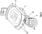
- Fig. 6 shows the working function of the upper and lower disk part 4, 1 with different stopping positions.
- the peak of the rotating pin 2 As the peak of the rotating pin 2 approaches the mating peak 24 of the first disk part 4 it tries to lift the first disk part 4 of the body side first door check part 20.
- the spring 5 provided above the first disk part 4 acts and constantly gives reaction on the first disk part 4, resulting in resistance to the door movement.
- This resistance is maximum at the point when the peak of the rotating pin or pins 2 coincides with the peak or peaks 24 of the first disk part 4, preferably at two opposing areas.
- the resistance starts dropping when the peaks of the pin and the first disk part cross each other and the resistance is zero when said peak of the rotating pin 2 matches the crest or indentation 22 formed between two peaks 24 of the first disk part 4. At this position the door movement is stopped/checked.
- the same phenomenon can be seen when peak of the rotating pin 2 approaches the next peak 24 of the first disk part 4. After passing over this second peak 24, the door 30 is in the full open condition and remains in this position.
- Fig. 4 shows the body side first door check part 20 separated from the door side second door check part 21, which is mounted in the door 30, by lifting the locking pin 9.
- Fig. 5 shows a front view of the first door check part 20 together with the second disk part 1 (left), and a top view of the first disk part 4 (right, top) and of the second disk part 1 (right, bottom).
- the first disk part 4 (right, top) is depicted with three indentations 22 or stop positions, namely A, where the door is closed, B an intermediate position, and C, a full open position of the door 30.
- the rotation movements that can be executed by the second disk part 1 when opening or closing the door 30 are depicted as arrows in the drawing at the right bottom.
- Fig. 7 shows a schematic top view of the door check assembly together with a body 31 and a door 30 and illustrates the working principle of the door check assembly with three possible stop positions A, B and C of the second door check part 21 and of the the door 30.
- Fig-7 shows the door check working principle with the rotation axis 25 of the hinges.
- Fig. 8 shows the same working principle and door stop positions A, Band C in a less schematic top view of the door check assembly compared to Fig. 7 .
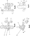
- Fig. 9a, b, c and d show a front, side, top and section view X-X of the door check assembly according to the invention as depicted in Fig. 2 .
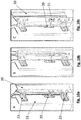
- Fig. 10a, b and c show the different door stop positions A, B and C for a vehicle with a door check assembly according to the invention, similar to Fig. 1 , but focused on the region of the door check assembly and therefore in the region of the first door check part 20 and the second door check part 21, mounted to the body 31 and to the door 30 respectively.
- the door check assembly is arranged between two door hinges 23, preferably approximately in the middle between the two hinges 23 of the door 30.
Landscapes
- Engineering & Computer Science (AREA)
- Mechanical Engineering (AREA)
- Body Structure For Vehicles (AREA)
- Hinge Accessories (AREA)
Abstract
Description
- The invention relates to a door check assembly for a vehicle door.
- Door checks, also called check straps, are used for vehicle doors, especially car doors, to allow the vehicle door to stop and to hold it at one or more specified intervals, while opening the door. They are useful for passenger ingress and egress. A conventional door check functions to stop the door at in-between positions as well as at an end position, i.e. at fully open condition.
- Door checks are known for example from
DE 1 584 202 A1DE 199 09 500 A1 . -
EP 1 068 416 A1 - It is an object of the invention to specify an improved door check assembly which can be used for a vehicle door. In particular, the intention is to specify a reliable and cost-effective door check assembly, which has a compact design.
- The object of the invention is achieved by means of a door check assembly for a vehicle door, comprising a first door check part which contains a body mounting part designed for mounting the first door check part to a body of the vehicle and a second door check part which contains a door mounting part designed for mounting the second door check part to a door of the vehicle, wherein the first door check part comprises a first disk part and the second door check part comprises a second disk part, wherein the first disk part is pivotally connected to the second disk part about a common center axis of the first and second disc part, wherein the first disk part and the second disk part are spring loaded against each other in the direction of the common center axis, wherein the first disk part or the second disk part has indentations as latching marks and the other of the second disk part and first disk part has a rotationally fixed pin which is moved into the indentations during a pivoting movement between the first and second disk part during opening or closing of the vehicle door.
- According to the invention a door check uses two disks, i.e. two flat parts, which are designed and arranged in a way, that the two parts can be rotated against each other. Therefore, the first and second disk part are arranged on a common center axis. The two disks are spring loaded in the direction of this common center axis against each other. One of the two disks comprises indentations and the other disk part comprises a pin which, depending on the angle of twist between the two discs, either lies in a recess (indentation) or lies in an elevated area between the recesses. In that way, further pivotal movement of the disks against each other becomes easier or harder, depending on the exact position of the disks in relation to each other, so that also the further pivotal movement of the first door check part in relation to the second door check part and of a vehicle door, connected to the first door check part, in relation to a vehicle body, connected to the second door check part, becomes easier or harder depending on the opening angle of the door.
- In this way the functionality of a door check is achieved with simple components that can be fixed to a body and a door of a vehicle and a door check projection into a door cavity, as in some other door check assemblies, is avoided, leading to a compact design of a door check stopper and an improved door packaging.
- Some further advantages that can be achieved with such a door check assembly, depending on its exact design, are:
The same parts can be utilized for all doors, also in different derivatives, for example in front driven and rear driven or in left-hand-drive and righthand-drive vehicles. Water tightness issues can be avoided. The cost of a rubber seal or a plastic housing can be saved. A dust protection cover can be provided. - The door check assembly can be very easy to assemble in an assembly line and can be easily serviceable. The solution can be produced in a cost-effective manner.
- Force adjustment can be carried out easily according to product requirement, fine-tuning on assembly-line is possible and re-adjustment in service case is also possible.
- The realization of several different door stop positions, for example with two stops or with three stops, is possible. A simple change of the disk part which has the indentations can be sufficient to alter the behavior of the door.
- Further advantageous embodiments and developments of the invention will become apparent from the dependent claims and from the description when considered together with the figures.
- It is advantageous if the door mounting part comprises a flange surface adapted to be mounted to a side surface of the vehicle door.
- It is also advantageous if the first disk part is non-rotatably mounted to the body mounting part and/or the second disk part is rotatably mounted to the body mounting part.
- Preferably the first disk part has the indentations and the second disk part has the rotationally fixed pin.
- Preferably the first disk part in the installation position lies above the second disk part.
- Preferably the door check assembly comprises a spring to spring-load the two disks against each other. Preferably the spring has the same center axis as the first and second disk part and is positioned, in the installation position, above the first disk part, to spring load the first disk part against the second disk part in the direction of the common center axis.
- It is advantageous that the pin is oriented diagonally with respect to the direction of the common center axis. In other embodiments the pin can be oriented parallel or normal to the common center axis.
- Preferably the second door check part contains an elongated link member, wherein a first end of the link member is pivotally connected to the second disk part and the second end of the link member, opposite the first end of the link member, is pivotally connected to the door mounting part.
- A vehicle according to the invention comprises a body of the vehicle, a door of the vehicle and a door check assembly as described above. The first door check part is mounted to the body via the body mounting part of the vehicle and the second door check part is mounted to the door via the door mounting part.
- Preferably the body mounting part is mounted to the vehicle body using bolts. Preferably the door mounting part is mounted to the vehicle door using bolts.
- Preferably the second door check part is mounted to a side surface of the door via the door mounting part.
- The present invention is explained in greater detail below with reference to the illustrative embodiments given in the schematic figures of the drawing, in which:
-
Fig. 1 shows different door stop positions for a vehicle with a door check assembly according to the invention; -
Fig. 2 shows a three-dimensional view of a door check assembly according to the invention; -
Fig. 3 shows a three-dimensional exploded view of the door check assembly ofFig. 2 ; -
Fig. 4 shows a three-dimensional view of the door check assembly ofFig. 2 , separated into the first door check part and the second door check part; -
Fig. 5 shows a front view of the first door check part of the door check assembly ofFig. 4 (left), and a top view of the first disk part (right, top) and the second disk part (right, bottom); -
Fig. 6 shows a three-dimensional view of the first disk part and the second disk part; -
Fig. 7 shows a schematic top view of the door check assembly together with a body and a door and shows the working principle of the door check assembly. -
Fig. 8 shows a less schematic top view of the door check assembly ofFig. 7 . -
Fig. 9a, b, c and d show front, side, top and section view of the door check assembly ofFig. 2 ; -
Fig. 10a, b and c show different door stop positions for a vehicle with a door check assembly according to the invention, similar toFig. 1 , but focused on the region of the door check assembly. -
Fig. 1 shows three different door stop positions (close position A, mid stop position B and open position C) for avehicle door 30, which is equipped with a door check assembly according to the invention. - The door check link assembly, comprising a first
door check part 20 and a seconddoor check part 21, is located between twodoor hinges 23, as can be seen in more detail inFig. 10a, b and c . Thedoor 30 is connected to thebody 31 of the vehicle by the door hinges 23 and by thedoor check assembly -
Fig. 2 shows a three-dimensional view of a door check assembly according to the invention.Fig. 3 shows the same door check assembly in an exploded view. - The door check assembly for a
vehicle door 30 comprises a firstdoor check part 20 which contains abody mounting part 7 designed for mounting the firstdoor check part 20 to abody 31 of the vehicle and a seconddoor check part 21 which contains adoor mounting part 8 designed for mounting the seconddoor check part 21 to thedoor 30 of the vehicle. - The
body mounting part 7 comprises a flange surface which can be mounted to a flat surface of the vehicle body using mountingbolts 10 and also thedoor mounting part 8 comprises a flange surface adapted to be mounted to a flat side surface of thevehicle door 30 using mountingbolts 10. - The first
door check part 20 comprises afirst disk part 4 and the seconddoor check part 21 comprises asecond disk part 1. Thefirst disk part 4, in the installation position, lies above thesecond disk part 1. - The
first disk part 4 is pivotally connected to thesecond disk part 1 about a common center axis of thefirst disk part 4 andsecond disk part 1. - The
first disk part 4 and thesecond disk part 1 are spring loaded against each other in the direction of the common center axis by aspring 5. Thespring 5 has the same center axis as the first andsecond disk part first disk part 4 and spring loads thefirst disk part 4 against thesecond disk part 1, in the direction of the common center axis. - The
first disk part 4 hasindentations 22 as latching marks. More precisely thefirst disk part 4 has two regions of indentations which face each other. - The
second disk part 1 has two rotationally fixedpins 2 which are moved into theindentations 22 during a pivoting movement between the first andsecond disk part vehicle door 30. Thepins 2 are oriented diagonally with respect to the direction of the common center axis. - The
first disk part 4 is non-rotatably mounted to thebody mounting part 20 and thesecond disk part 1 is rotatably mounted to thebody mounting part 20. - The second
door check part 21 contains anelongated link member 3. A first end of thelink member 3 is pivotally connected to thesecond disk part 1 by using alocking pin 9 as a rotary axis and the second end of thelink member 3, opposite the first end of the link member, is pivotally connected to thedoor mounting part 8, also by using alocking pin 9 as a rotary axis. - In this solution, the upper sector part or
first disk part 4 is driven by thebody mounting part 7 and the lower sector part orsecond disk part 1 is driven by thedoor mounting part 8. - When the
door 30 is set to open, thelink member 3 and thesecond disk part 1 of the seconddoor check part 21 moves with thedoor 30 and tries to take along thefirst disk part 4 of the firstdoor check part 20. - As can be seen most clearly in
Fig. 6 , the rotatingpins 2 connect the first andsecond disk part parts -
Fig. 6 shows the working function of the upper andlower disk part - As the peak of the
rotating pin 2 approaches themating peak 24 of thefirst disk part 4 it tries to lift thefirst disk part 4 of the body side firstdoor check part 20. Thespring 5 provided above thefirst disk part 4 acts and constantly gives reaction on thefirst disk part 4, resulting in resistance to the door movement. This resistance is maximum at the point when the peak of the rotating pin or pins 2 coincides with the peak or peaks 24 of thefirst disk part 4, preferably at two opposing areas. The resistance starts dropping when the peaks of the pin and the first disk part cross each other and the resistance is zero when said peak of therotating pin 2 matches the crest orindentation 22 formed between twopeaks 24 of thefirst disk part 4. At this position the door movement is stopped/checked. The same phenomenon can be seen when peak of therotating pin 2 approaches thenext peak 24 of thefirst disk part 4. After passing over thissecond peak 24, thedoor 30 is in the full open condition and remains in this position. - While closing the
door 30, it goes through the same cycle but in reverse order to have again the same door check performance. -
Fig. 4 shows the body side firstdoor check part 20 separated from the door side seconddoor check part 21, which is mounted in thedoor 30, by lifting thelocking pin 9. -
Fig. 5 shows a front view of the firstdoor check part 20 together with the second disk part 1 (left), and a top view of the first disk part 4 (right, top) and of the second disk part 1 (right, bottom). The first disk part 4 (right, top) is depicted with threeindentations 22 or stop positions, namely A, where the door is closed, B an intermediate position, and C, a full open position of thedoor 30. The rotation movements that can be executed by thesecond disk part 1 when opening or closing thedoor 30 are depicted as arrows in the drawing at the right bottom. -
Fig. 7 shows a schematic top view of the door check assembly together with abody 31 and adoor 30 and illustrates the working principle of the door check assembly with three possible stop positions A, B and C of the seconddoor check part 21 and of the thedoor 30. Fig-7 shows the door check working principle with therotation axis 25 of the hinges. -
Fig. 8 shows the same working principle and door stop positions A, Band C in a less schematic top view of the door check assembly compared toFig. 7 . -
Fig. 9a, b, c and d show a front, side, top and section view X-X of the door check assembly according to the invention as depicted inFig. 2 . - Finally,
Fig. 10a, b and c show the different door stop positions A, B and C for a vehicle with a door check assembly according to the invention, similar toFig. 1 , but focused on the region of the door check assembly and therefore in the region of the firstdoor check part 20 and the seconddoor check part 21, mounted to thebody 31 and to thedoor 30 respectively. The door check assembly is arranged between two door hinges 23, preferably approximately in the middle between the two hinges 23 of thedoor 30. -
- 1
- second disk part
- 2
- pin
- 3
- link member
- 4
- first disk part
- 5
- spring
- 6
- locking nut
- 7
- body mounting part
- 8
- door mounting part
- 9
- locking pin
- 10
- mounting bolt
- 20
- first door check part
- 21
- second door check part
- 22
- indentation
- 23
- door hinges
- 24
- peak
- 25
- rotation axis of a hinge
- 30
- door
- 31
- body
- A
- door closed position
- B
- door intermediate position
- C
- door full open position
- X-X
- section
Claims (9)
- Door check assembly for a vehicle door (30), comprising a first door check part (20) which contains a body mounting part (7) designed for mounting the first door check part (20) to a body (31) of the vehicle and a second door check part (21) which contains a door mounting part (8) designed for mounting the second door check part (21) to the door (30) of the vehicle, wherein the first door check part (20) comprises a first disk part (4) and the second door check part (21) comprises a second disk part (1), wherein the first disk part (4) is pivotally connected to the second disk part (1) about a common center axis of the first and second disc part (4, 1), wherein the first disk part (4) and the second disk part (1) are spring loaded against each other in the direction of the common center axis, wherein the first disk part (4) or the second disk part (1) has indentations (22) as latching marks and the other of the second disk part (1) and first disk part (4) has a rotationally fixed pin (2) which is moved into the indentations (22) during a pivoting movement between the first and second disk part (4, 1) during opening or closing of the vehicle door (30).
- Door check assembly according to claim 1,
characterized in that the door mounting part (8) comprises a flange surface adapted to be mounted to a side surface of the vehicle door (30). - Door check assembly according to any of the preceding claims,
characterized in that the first disk part (4) is non-rotatably mounted to the body mounting part (20) and/or the second disk part (1) is rotatably mounted to the body mounting part (20). - Door check assembly according to any of the preceding claims,
characterized in that the first disk part (4) has the indentations (22) and the second disk part (1) has the rotationally fixed pin (2). - Door check assembly according to any of the preceding claims,
characterized in that the first disk part (4) in the installation position lies above the second disk part (1). - Door check assembly according to claim 5,
characterized in that a spring (5), which has the same center axis as the first and second disk part (4, 1), is positioned in the installation position above the first disk part (4), to spring load the first disk part (4) against the second disk part (1) in the direction of the common center axis. - Door check assembly according to any of the preceding claims,
characterized in that the pin (2) is oriented diagonally with respect to the direction of the common center axis. - Door check assembly according to any of the preceding claims,
characterized in that the second door check part (21) contains an elongated link member (3), wherein a first end of the link member (3) is pivotally connected to the second disk part (1) and the second end of the link member (3), opposite the first end of the link member, is pivotally connected to the door mounting part (8). - Vehicle comprising a body (31) of the vehicle, a door (30) of the vehicle and a door check assembly according to any of the preceding claims,
characterized in that the first door check part (20) is mounted to the body (31) via the body mounting part (7) and the second door check part (21) is mounted to the door (30) via the door mounting part (8), wherein preferably the second door check part (21) is mounted to a side surface of the door (30) via the door mounting part (8).
Priority Applications (1)
| Application Number | Priority Date | Filing Date | Title |
|---|---|---|---|
| EP19202429.7A EP3805497B1 (en) | 2019-10-10 | 2019-10-10 | Door check assembly |
Applications Claiming Priority (1)
| Application Number | Priority Date | Filing Date | Title |
|---|---|---|---|
| EP19202429.7A EP3805497B1 (en) | 2019-10-10 | 2019-10-10 | Door check assembly |
Publications (2)
| Publication Number | Publication Date |
|---|---|
| EP3805497A1 true EP3805497A1 (en) | 2021-04-14 |
| EP3805497B1 EP3805497B1 (en) | 2022-06-22 |
Family
ID=68392688
Family Applications (1)
| Application Number | Title | Priority Date | Filing Date |
|---|---|---|---|
| EP19202429.7A Active EP3805497B1 (en) | 2019-10-10 | 2019-10-10 | Door check assembly |
Country Status (1)
| Country | Link |
|---|---|
| EP (1) | EP3805497B1 (en) |
Cited By (1)
| Publication number | Priority date | Publication date | Assignee | Title |
|---|---|---|---|---|
| US11725435B2 (en) | 2021-10-01 | 2023-08-15 | Michael A Papoulias | Door hinge limiter for automotive vehicle |
Citations (8)
| Publication number | Priority date | Publication date | Assignee | Title |
|---|---|---|---|---|
| DE1584202A1 (en) | 1966-05-27 | 1969-12-18 | Scharwaechter Kg | Door hinge for motor vehicles |
| US6029314A (en) * | 1997-08-12 | 2000-02-29 | Ed. Scharwachter Gmbh | Door lock formed integrally with a separable door hinge for a motor vehicle door |
| DE19909500A1 (en) | 1999-03-04 | 2000-09-07 | Wilfried Ball | Door check strap for vehicle door hinge has spring-loaded movable part formed by three-dimensionally shaped sheet metal pressed part containing detent mark and opening end stop |
| EP1068416A1 (en) | 1998-04-03 | 2001-01-17 | ED. Scharwächter GmbH | Motor vehicle door stop |
| US6282752B1 (en) * | 1996-05-14 | 2001-09-04 | ED. SCHARWäCHTER GMBH & CO. KG | Door hinge assembly with integrated door lock for a motor vehicle door |
| US6516495B1 (en) * | 1998-11-26 | 2003-02-11 | Ed. Scharwaechter Gmbh | Door arrester which is joined to a door hinge, for automobile doors |
| US7908712B2 (en) * | 2004-10-12 | 2011-03-22 | Edscha Ag | Hinge for a vehicle door |
| WO2017074284A1 (en) * | 2015-10-28 | 2017-05-04 | Rollmech Automotive Sanayi Ve Ticaret Anonim Sirketi | A hinge with a door holder arm |
-
2019
- 2019-10-10 EP EP19202429.7A patent/EP3805497B1/en active Active
Patent Citations (8)
| Publication number | Priority date | Publication date | Assignee | Title |
|---|---|---|---|---|
| DE1584202A1 (en) | 1966-05-27 | 1969-12-18 | Scharwaechter Kg | Door hinge for motor vehicles |
| US6282752B1 (en) * | 1996-05-14 | 2001-09-04 | ED. SCHARWäCHTER GMBH & CO. KG | Door hinge assembly with integrated door lock for a motor vehicle door |
| US6029314A (en) * | 1997-08-12 | 2000-02-29 | Ed. Scharwachter Gmbh | Door lock formed integrally with a separable door hinge for a motor vehicle door |
| EP1068416A1 (en) | 1998-04-03 | 2001-01-17 | ED. Scharwächter GmbH | Motor vehicle door stop |
| US6516495B1 (en) * | 1998-11-26 | 2003-02-11 | Ed. Scharwaechter Gmbh | Door arrester which is joined to a door hinge, for automobile doors |
| DE19909500A1 (en) | 1999-03-04 | 2000-09-07 | Wilfried Ball | Door check strap for vehicle door hinge has spring-loaded movable part formed by three-dimensionally shaped sheet metal pressed part containing detent mark and opening end stop |
| US7908712B2 (en) * | 2004-10-12 | 2011-03-22 | Edscha Ag | Hinge for a vehicle door |
| WO2017074284A1 (en) * | 2015-10-28 | 2017-05-04 | Rollmech Automotive Sanayi Ve Ticaret Anonim Sirketi | A hinge with a door holder arm |
Cited By (2)
| Publication number | Priority date | Publication date | Assignee | Title |
|---|---|---|---|---|
| US11725435B2 (en) | 2021-10-01 | 2023-08-15 | Michael A Papoulias | Door hinge limiter for automotive vehicle |
| US11905745B2 (en) | 2021-10-01 | 2024-02-20 | Michael A Papoulias | Door hinge limiter for automotive vehicle |
Also Published As
| Publication number | Publication date |
|---|---|
| EP3805497B1 (en) | 2022-06-22 |
Similar Documents
| Publication | Publication Date | Title |
|---|---|---|
| US6938303B2 (en) | Double pivot concealed hinge | |
| US11383672B2 (en) | Active pedestrian hood hinge with integrated latch assembly | |
| US6739020B1 (en) | Door hinge with an integrated door stop | |
| CA2636847C (en) | Checker-equipped door hinge device for vehicle | |
| US7096536B2 (en) | Hinge apparatus with check mechanism | |
| US9695621B2 (en) | Hinged door with hinge plate | |
| US6684455B1 (en) | Articulated joint, in particular a door hinge, having a device for fastening a first movement element | |
| US20100139044A1 (en) | Checker-equipped door hinge device for vehicle | |
| CN104169510A (en) | car door lock | |
| US6728993B1 (en) | Structure for pivotally supporting check plate of door checker | |
| US4266321A (en) | Hinge and hold-open assembly | |
| CA2276839C (en) | Door hinge system | |
| EP3805497B1 (en) | Door check assembly | |
| EP2072729B1 (en) | Hinge for vehicle door, in particular of a van | |
| US6457207B1 (en) | Stop arrangement for a pivotable door | |
| KR20010082129A (en) | Pivotless automotive hinge | |
| CN101389823B (en) | Articulation | |
| US6473937B1 (en) | Motor vehicle door hinge having an integrated braking and holding function | |
| US20130232882A1 (en) | Articulating members for closure systems | |
| GB2215775A (en) | Hinges | |
| US20020050026A1 (en) | Hinge for a motor vehicle rear door | |
| KR960016478B1 (en) | Car door hinges | |
| US20240410212A1 (en) | Vehicle closure member hinge assemblies with internal stop features | |
| US20080169659A1 (en) | Door Stop With Indeterminate Retaining Positions | |
| US6273501B1 (en) | Simplified wind deflector for vehicle roof closure |
Legal Events
| Date | Code | Title | Description |
|---|---|---|---|
| PUAI | Public reference made under article 153(3) epc to a published international application that has entered the european phase |
Free format text: ORIGINAL CODE: 0009012 |
|
| STAA | Information on the status of an ep patent application or granted ep patent |
Free format text: STATUS: REQUEST FOR EXAMINATION WAS MADE |
|
| 17P | Request for examination filed |
Effective date: 20201216 |
|
| AK | Designated contracting states |
Kind code of ref document: A1 Designated state(s): AL AT BE BG CH CY CZ DE DK EE ES FI FR GB GR HR HU IE IS IT LI LT LU LV MC MK MT NL NO PL PT RO RS SE SI SK SM TR |
|
| AX | Request for extension of the european patent |
Extension state: BA ME |
|
| GRAP | Despatch of communication of intention to grant a patent |
Free format text: ORIGINAL CODE: EPIDOSNIGR1 |
|
| STAA | Information on the status of an ep patent application or granted ep patent |
Free format text: STATUS: GRANT OF PATENT IS INTENDED |
|
| INTG | Intention to grant announced |
Effective date: 20220128 |
|
| GRAS | Grant fee paid |
Free format text: ORIGINAL CODE: EPIDOSNIGR3 |
|
| GRAA | (expected) grant |
Free format text: ORIGINAL CODE: 0009210 |
|
| STAA | Information on the status of an ep patent application or granted ep patent |
Free format text: STATUS: THE PATENT HAS BEEN GRANTED |
|
| AK | Designated contracting states |
Kind code of ref document: B1 Designated state(s): AL AT BE BG CH CY CZ DE DK EE ES FI FR GB GR HR HU IE IS IT LI LT LU LV MC MK MT NL NO PL PT RO RS SE SI SK SM TR |
|
| REG | Reference to a national code |
Ref country code: GB Ref legal event code: FG4D |
|
| REG | Reference to a national code |
Ref country code: CH Ref legal event code: EP |
|
| REG | Reference to a national code |
Ref country code: DE Ref legal event code: R096 Ref document number: 602019016109 Country of ref document: DE |
|
| REG | Reference to a national code |
Ref country code: AT Ref legal event code: REF Ref document number: 1499875 Country of ref document: AT Kind code of ref document: T Effective date: 20220715 |
|
| REG | Reference to a national code |
Ref country code: IE Ref legal event code: FG4D |
|
| REG | Reference to a national code |
Ref country code: LT Ref legal event code: MG9D |
|
| REG | Reference to a national code |
Ref country code: DE Ref legal event code: R081 Ref document number: 602019016109 Country of ref document: DE Owner name: MAGNA STEYR FAHRZEUGTECHNIK GMBH & CO KG, AT Free format text: FORMER OWNER: MAGNA STEYR FAHRZEUGTECHNIK AG & CO KG, GRAZ, AT |
|
| REG | Reference to a national code |
Ref country code: NL Ref legal event code: MP Effective date: 20220622 |
|
| PG25 | Lapsed in a contracting state [announced via postgrant information from national office to epo] |
Ref country code: SE Free format text: LAPSE BECAUSE OF FAILURE TO SUBMIT A TRANSLATION OF THE DESCRIPTION OR TO PAY THE FEE WITHIN THE PRESCRIBED TIME-LIMIT Effective date: 20220622 Ref country code: NO Free format text: LAPSE BECAUSE OF FAILURE TO SUBMIT A TRANSLATION OF THE DESCRIPTION OR TO PAY THE FEE WITHIN THE PRESCRIBED TIME-LIMIT Effective date: 20220922 Ref country code: LT Free format text: LAPSE BECAUSE OF FAILURE TO SUBMIT A TRANSLATION OF THE DESCRIPTION OR TO PAY THE FEE WITHIN THE PRESCRIBED TIME-LIMIT Effective date: 20220622 Ref country code: HR Free format text: LAPSE BECAUSE OF FAILURE TO SUBMIT A TRANSLATION OF THE DESCRIPTION OR TO PAY THE FEE WITHIN THE PRESCRIBED TIME-LIMIT Effective date: 20220622 Ref country code: GR Free format text: LAPSE BECAUSE OF FAILURE TO SUBMIT A TRANSLATION OF THE DESCRIPTION OR TO PAY THE FEE WITHIN THE PRESCRIBED TIME-LIMIT Effective date: 20220923 Ref country code: FI Free format text: LAPSE BECAUSE OF FAILURE TO SUBMIT A TRANSLATION OF THE DESCRIPTION OR TO PAY THE FEE WITHIN THE PRESCRIBED TIME-LIMIT Effective date: 20220622 Ref country code: BG Free format text: LAPSE BECAUSE OF FAILURE TO SUBMIT A TRANSLATION OF THE DESCRIPTION OR TO PAY THE FEE WITHIN THE PRESCRIBED TIME-LIMIT Effective date: 20220922 |
|
| REG | Reference to a national code |
Ref country code: AT Ref legal event code: MK05 Ref document number: 1499875 Country of ref document: AT Kind code of ref document: T Effective date: 20220622 |
|
| PG25 | Lapsed in a contracting state [announced via postgrant information from national office to epo] |
Ref country code: RS Free format text: LAPSE BECAUSE OF FAILURE TO SUBMIT A TRANSLATION OF THE DESCRIPTION OR TO PAY THE FEE WITHIN THE PRESCRIBED TIME-LIMIT Effective date: 20220622 Ref country code: LV Free format text: LAPSE BECAUSE OF FAILURE TO SUBMIT A TRANSLATION OF THE DESCRIPTION OR TO PAY THE FEE WITHIN THE PRESCRIBED TIME-LIMIT Effective date: 20220622 |
|
| PG25 | Lapsed in a contracting state [announced via postgrant information from national office to epo] |
Ref country code: NL Free format text: LAPSE BECAUSE OF FAILURE TO SUBMIT A TRANSLATION OF THE DESCRIPTION OR TO PAY THE FEE WITHIN THE PRESCRIBED TIME-LIMIT Effective date: 20220622 |
|
| PG25 | Lapsed in a contracting state [announced via postgrant information from national office to epo] |
Ref country code: SM Free format text: LAPSE BECAUSE OF FAILURE TO SUBMIT A TRANSLATION OF THE DESCRIPTION OR TO PAY THE FEE WITHIN THE PRESCRIBED TIME-LIMIT Effective date: 20220622 Ref country code: SK Free format text: LAPSE BECAUSE OF FAILURE TO SUBMIT A TRANSLATION OF THE DESCRIPTION OR TO PAY THE FEE WITHIN THE PRESCRIBED TIME-LIMIT Effective date: 20220622 Ref country code: RO Free format text: LAPSE BECAUSE OF FAILURE TO SUBMIT A TRANSLATION OF THE DESCRIPTION OR TO PAY THE FEE WITHIN THE PRESCRIBED TIME-LIMIT Effective date: 20220622 Ref country code: PT Free format text: LAPSE BECAUSE OF FAILURE TO SUBMIT A TRANSLATION OF THE DESCRIPTION OR TO PAY THE FEE WITHIN THE PRESCRIBED TIME-LIMIT Effective date: 20221024 Ref country code: ES Free format text: LAPSE BECAUSE OF FAILURE TO SUBMIT A TRANSLATION OF THE DESCRIPTION OR TO PAY THE FEE WITHIN THE PRESCRIBED TIME-LIMIT Effective date: 20220622 Ref country code: EE Free format text: LAPSE BECAUSE OF FAILURE TO SUBMIT A TRANSLATION OF THE DESCRIPTION OR TO PAY THE FEE WITHIN THE PRESCRIBED TIME-LIMIT Effective date: 20220622 Ref country code: CZ Free format text: LAPSE BECAUSE OF FAILURE TO SUBMIT A TRANSLATION OF THE DESCRIPTION OR TO PAY THE FEE WITHIN THE PRESCRIBED TIME-LIMIT Effective date: 20220622 Ref country code: AT Free format text: LAPSE BECAUSE OF FAILURE TO SUBMIT A TRANSLATION OF THE DESCRIPTION OR TO PAY THE FEE WITHIN THE PRESCRIBED TIME-LIMIT Effective date: 20220622 |
|
| PG25 | Lapsed in a contracting state [announced via postgrant information from national office to epo] |
Ref country code: PL Free format text: LAPSE BECAUSE OF FAILURE TO SUBMIT A TRANSLATION OF THE DESCRIPTION OR TO PAY THE FEE WITHIN THE PRESCRIBED TIME-LIMIT Effective date: 20220622 Ref country code: IS Free format text: LAPSE BECAUSE OF FAILURE TO SUBMIT A TRANSLATION OF THE DESCRIPTION OR TO PAY THE FEE WITHIN THE PRESCRIBED TIME-LIMIT Effective date: 20221022 |
|
| REG | Reference to a national code |
Ref country code: DE Ref legal event code: R097 Ref document number: 602019016109 Country of ref document: DE |
|
| PG25 | Lapsed in a contracting state [announced via postgrant information from national office to epo] |
Ref country code: AL Free format text: LAPSE BECAUSE OF FAILURE TO SUBMIT A TRANSLATION OF THE DESCRIPTION OR TO PAY THE FEE WITHIN THE PRESCRIBED TIME-LIMIT Effective date: 20220622 |
|
| PG25 | Lapsed in a contracting state [announced via postgrant information from national office to epo] |
Ref country code: DK Free format text: LAPSE BECAUSE OF FAILURE TO SUBMIT A TRANSLATION OF THE DESCRIPTION OR TO PAY THE FEE WITHIN THE PRESCRIBED TIME-LIMIT Effective date: 20220622 |
|
| PLBE | No opposition filed within time limit |
Free format text: ORIGINAL CODE: 0009261 |
|
| STAA | Information on the status of an ep patent application or granted ep patent |
Free format text: STATUS: NO OPPOSITION FILED WITHIN TIME LIMIT |
|
| 26N | No opposition filed |
Effective date: 20230323 |
|
| PG25 | Lapsed in a contracting state [announced via postgrant information from national office to epo] |
Ref country code: MC Free format text: LAPSE BECAUSE OF FAILURE TO SUBMIT A TRANSLATION OF THE DESCRIPTION OR TO PAY THE FEE WITHIN THE PRESCRIBED TIME-LIMIT Effective date: 20220622 |
|
| REG | Reference to a national code |
Ref country code: CH Ref legal event code: PL |
|
| REG | Reference to a national code |
Ref country code: BE Ref legal event code: MM Effective date: 20221031 |
|
| PG25 | Lapsed in a contracting state [announced via postgrant information from national office to epo] |
Ref country code: LU Free format text: LAPSE BECAUSE OF NON-PAYMENT OF DUE FEES Effective date: 20221010 |
|
| PG25 | Lapsed in a contracting state [announced via postgrant information from national office to epo] |
Ref country code: LI Free format text: LAPSE BECAUSE OF NON-PAYMENT OF DUE FEES Effective date: 20221031 Ref country code: FR Free format text: LAPSE BECAUSE OF NON-PAYMENT OF DUE FEES Effective date: 20221031 Ref country code: CH Free format text: LAPSE BECAUSE OF NON-PAYMENT OF DUE FEES Effective date: 20221031 |
|
| PG25 | Lapsed in a contracting state [announced via postgrant information from national office to epo] |
Ref country code: SI Free format text: LAPSE BECAUSE OF FAILURE TO SUBMIT A TRANSLATION OF THE DESCRIPTION OR TO PAY THE FEE WITHIN THE PRESCRIBED TIME-LIMIT Effective date: 20220622 |
|
| PG25 | Lapsed in a contracting state [announced via postgrant information from national office to epo] |
Ref country code: BE Free format text: LAPSE BECAUSE OF NON-PAYMENT OF DUE FEES Effective date: 20221031 |
|
| PG25 | Lapsed in a contracting state [announced via postgrant information from national office to epo] |
Ref country code: IE Free format text: LAPSE BECAUSE OF NON-PAYMENT OF DUE FEES Effective date: 20221010 |
|
| PG25 | Lapsed in a contracting state [announced via postgrant information from national office to epo] |
Ref country code: IT Free format text: LAPSE BECAUSE OF FAILURE TO SUBMIT A TRANSLATION OF THE DESCRIPTION OR TO PAY THE FEE WITHIN THE PRESCRIBED TIME-LIMIT Effective date: 20220622 |
|
| PG25 | Lapsed in a contracting state [announced via postgrant information from national office to epo] |
Ref country code: CY Free format text: LAPSE BECAUSE OF FAILURE TO SUBMIT A TRANSLATION OF THE DESCRIPTION OR TO PAY THE FEE WITHIN THE PRESCRIBED TIME-LIMIT Effective date: 20220622 |
|
| PG25 | Lapsed in a contracting state [announced via postgrant information from national office to epo] |
Ref country code: MK Free format text: LAPSE BECAUSE OF FAILURE TO SUBMIT A TRANSLATION OF THE DESCRIPTION OR TO PAY THE FEE WITHIN THE PRESCRIBED TIME-LIMIT Effective date: 20220622 Ref country code: HU Free format text: LAPSE BECAUSE OF FAILURE TO SUBMIT A TRANSLATION OF THE DESCRIPTION OR TO PAY THE FEE WITHIN THE PRESCRIBED TIME-LIMIT; INVALID AB INITIO Effective date: 20191010 |
|
| GBPC | Gb: european patent ceased through non-payment of renewal fee |
Effective date: 20231010 |
|
| PG25 | Lapsed in a contracting state [announced via postgrant information from national office to epo] |
Ref country code: TR Free format text: LAPSE BECAUSE OF FAILURE TO SUBMIT A TRANSLATION OF THE DESCRIPTION OR TO PAY THE FEE WITHIN THE PRESCRIBED TIME-LIMIT Effective date: 20220622 |
|
| PG25 | Lapsed in a contracting state [announced via postgrant information from national office to epo] |
Ref country code: GB Free format text: LAPSE BECAUSE OF NON-PAYMENT OF DUE FEES Effective date: 20231010 |
|
| PG25 | Lapsed in a contracting state [announced via postgrant information from national office to epo] |
Ref country code: GB Free format text: LAPSE BECAUSE OF NON-PAYMENT OF DUE FEES Effective date: 20231010 |
|
| PG25 | Lapsed in a contracting state [announced via postgrant information from national office to epo] |
Ref country code: MT Free format text: LAPSE BECAUSE OF FAILURE TO SUBMIT A TRANSLATION OF THE DESCRIPTION OR TO PAY THE FEE WITHIN THE PRESCRIBED TIME-LIMIT Effective date: 20220622 |
|
| PG25 | Lapsed in a contracting state [announced via postgrant information from national office to epo] |
Ref country code: BG Free format text: LAPSE BECAUSE OF FAILURE TO SUBMIT A TRANSLATION OF THE DESCRIPTION OR TO PAY THE FEE WITHIN THE PRESCRIBED TIME-LIMIT Effective date: 20220622 |
|
| PG25 | Lapsed in a contracting state [announced via postgrant information from national office to epo] |
Ref country code: BG Free format text: LAPSE BECAUSE OF FAILURE TO SUBMIT A TRANSLATION OF THE DESCRIPTION OR TO PAY THE FEE WITHIN THE PRESCRIBED TIME-LIMIT Effective date: 20220622 |
|
| REG | Reference to a national code |
Ref country code: DE Ref legal event code: R082 Ref document number: 602019016109 Country of ref document: DE Representative=s name: EULER, MATTHIAS, DR., DE |
|
| PGFP | Annual fee paid to national office [announced via postgrant information from national office to epo] |
Ref country code: DE Payment date: 20251021 Year of fee payment: 7 |