EP3805452A1 - Refiner - Google Patents
Refiner Download PDFInfo
- Publication number
- EP3805452A1 EP3805452A1 EP20198743.5A EP20198743A EP3805452A1 EP 3805452 A1 EP3805452 A1 EP 3805452A1 EP 20198743 A EP20198743 A EP 20198743A EP 3805452 A1 EP3805452 A1 EP 3805452A1
- Authority
- EP
- European Patent Office
- Prior art keywords
- refining
- refiner
- fibre material
- zone
- chamber
- Prior art date
- Legal status (The legal status is an assumption and is not a legal conclusion. Google has not performed a legal analysis and makes no representation as to the accuracy of the status listed.)
- Pending
Links
Images


Classifications
-
- D—TEXTILES; PAPER
- D21—PAPER-MAKING; PRODUCTION OF CELLULOSE
- D21D—TREATMENT OF THE MATERIALS BEFORE PASSING TO THE PAPER-MAKING MACHINE
- D21D1/00—Methods of beating or refining; Beaters of the Hollander type
- D21D1/20—Methods of refining
- D21D1/22—Jordans
- D21D1/26—Jordan bed plates
-
- D—TEXTILES; PAPER
- D21—PAPER-MAKING; PRODUCTION OF CELLULOSE
- D21D—TREATMENT OF THE MATERIALS BEFORE PASSING TO THE PAPER-MAKING MACHINE
- D21D1/00—Methods of beating or refining; Beaters of the Hollander type
- D21D1/20—Methods of refining
-
- D—TEXTILES; PAPER
- D21—PAPER-MAKING; PRODUCTION OF CELLULOSE
- D21D—TREATMENT OF THE MATERIALS BEFORE PASSING TO THE PAPER-MAKING MACHINE
- D21D1/00—Methods of beating or refining; Beaters of the Hollander type
- D21D1/20—Methods of refining
- D21D1/30—Disc mills
- D21D1/303—Double disc mills
-
- D—TEXTILES; PAPER
- D21—PAPER-MAKING; PRODUCTION OF CELLULOSE
- D21D—TREATMENT OF THE MATERIALS BEFORE PASSING TO THE PAPER-MAKING MACHINE
- D21D1/00—Methods of beating or refining; Beaters of the Hollander type
- D21D1/20—Methods of refining
- D21D1/22—Jordans
-
- D—TEXTILES; PAPER
- D21—PAPER-MAKING; PRODUCTION OF CELLULOSE
- D21D—TREATMENT OF THE MATERIALS BEFORE PASSING TO THE PAPER-MAKING MACHINE
- D21D1/00—Methods of beating or refining; Beaters of the Hollander type
- D21D1/20—Methods of refining
- D21D1/30—Disc mills
-
- D—TEXTILES; PAPER
- D21—PAPER-MAKING; PRODUCTION OF CELLULOSE
- D21D—TREATMENT OF THE MATERIALS BEFORE PASSING TO THE PAPER-MAKING MACHINE
- D21D1/00—Methods of beating or refining; Beaters of the Hollander type
- D21D1/20—Methods of refining
- D21D1/30—Disc mills
- D21D1/306—Discs
-
- D—TEXTILES; PAPER
- D21—PAPER-MAKING; PRODUCTION OF CELLULOSE
- D21D—TREATMENT OF THE MATERIALS BEFORE PASSING TO THE PAPER-MAKING MACHINE
- D21D1/00—Methods of beating or refining; Beaters of the Hollander type
- D21D1/20—Methods of refining
- D21D1/34—Other mills or refiners
- D21D1/38—Other mills or refiners with horizontal shaft
Definitions
- the invention relates to a refiner and a method for refining lignocellulose-containing fibre material.
- one or more lignocellulose-containing wood-based fibre material fractions of different quality may be mixed for manufacturing the paper or board web.
- the mixing of the fibre material fractions of different quality takes places for example due to a need to obtain a combination of various kind of properties in the end product, such as a specific tensile strength with a specific grammage.
- the fibre material fractions of different quality may include for example virgin hardwood and softwood-based fibre pulps as well as different recycled fibre materials, such as long-fibred and short-fibred pulps made of OCC (Old Corrugated Container).
- the mixed pulp is manufactured by mixing at least two fibre material fractions of different quality from separate storage tanks, each specific storage tank being reserved for the single fibre material fraction of specific quality.
- single fibre material may contain different qualities, such as OCC that contains both long-fibred fraction and short-fibred fraction.
- the number of the refiners may be reduced by first mixing at least two fibre material fractions of different quality with each other, or having one fibre material with a large fibre length distribution, like the OCC, and thereafter refining the fibre material pulp with a single refiner.
- the refining surface characteristics of the refiner are a compromise based on the refining needs of the fibre material fractions forming the pulp. Therefore, the quality of the mixed pulp after refining is not necessarily as high as the quality of the pulp formed by mixing at least two separately refined fibre material fractions as disclosed above.
- An object of the present invention is to provide a novel refiner and a method for refining lignocellulose-containing fibre material.
- the idea of the invention is to simultaneously refine with a single refiner at least two flows of at least one fibre material fraction at different refining zones in the single refiner, refining surface characteristics of the different refining zones being specifically designed in view of the fibre material fraction to be refined at the refining zone as well as in view of the intended refining effect to be subjected to the fibre material fraction at the refining zone. It is thus possible to feed into the refiner at least two flows of fibre material, which two flows may be either one and same fibre material fraction or different fibre material fractions of different qualities.
- An advantage of the invention is that it is possible with a single refiner to refine simultaneously at least one fibre material fraction with different refining effects to be subjected to the at least one fibre material fraction, whereby the fibre material portions subjected to the different refining effects may for example be directed to different layers in the paper or board web to be manufactured or into different processes.
- the refiner of this kind is especially useful in applications wherein required amounts or volumes of different fibre material fractions for the production of the paper or board are moderate.
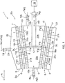
- Figure 1 is a very schematic side view of a conical refiner 1 partly in cross-section, which conical refiner 1 may be utilized to refine lignocellulose-containing wood-based fibre material.
- the refiner 1 has a first end Ea of smaller diameter and a second end Eb of larger diameter.
- the refiner 1 comprises a stationary refining element 6, i.e. a stator 6, having a first end facing towards the first end Ea of the refiner 1 and a second end facing towards the second end Eb of the refiner 1, and therefore, for the sake of clarity, the reference sign Ea is also used to denote the first end of the stator 6 and the reference sign Eb is also used to denote the second end of the stator 6.
- the stator 6 is supported to a frame structure 5 of the refiner 1.
- the stator 6 comprises a number of stator blade elements 7 having a refining surface 8, the refining surface 8 of each stator blade element 7 contributing to provide a complete refining surface of the stator 6.
- the stator blade element 7 has a first end facing towards the first end Ea of the refiner 1 and a second end facing towards the second end Eb of the refiner 1, and therefore, for the sake of clarity, the reference sign Ea is also used to denote the first end of the stator blade element 7 and the reference sign Eb is also used to denote the second end of the stator blade element 7.
- stator 6 it may comprise only one blade element 7 of a conical shape and extending over a whole periphery of the stator 6 so that the refining surface 8 of this single blade element provides a complete uniform refining surface of the stator 6.
- stator 6 it may comprise at least two segment-like blade elements, i.e. blade segments that are arranged adjacent to one another whereby the refining surfaces 8 of the originally separate segment-like blade elements together provide the complete uniform refining surface of the stator 6.
- blade element when referring to the stator 6 of the refiner 1, may thus refer to a single blade element providing the complete refining surface of the stator 6 or to a blade segment providing only a part of the complete refining surface of the stator 6.
- the same reference number 8 may be used below to denote both the refining surface 8 of a single blade element 7 for the stator 6 as well as the complete refining surface 8 of the stator 6.
- the refining surface 8 in the stator 6 is typically provided with blade bars and blade grooves therebetween, an embodiment of some blade bars and blade grooves being shown later in Figure 2 .
- the refiner 1 further comprises a rotatable refining element 9, i.e. a rotor 9, having a first end facing towards the first end Ea of the refiner 1 and a second end facing towards the second end Eb of the refiner 1, and therefore, for the sake of clarity, the reference sign Ea is also used to denote the first end of the rotor 9 and the reference sign Eb is also used to denote the second end of the rotor 9.
- a rotatable refining element 9 i.e. a rotor 9 having a first end facing towards the first end Ea of the refiner 1 and a second end facing towards the second end Eb of the refiner 1, and therefore, for the sake of clarity, the reference sign Ea is also used to denote the first end of the rotor 9 and the reference sign Eb is also used to denote the second end of the rotor 9.
- the rotor 9 comprises a number of rotor blade elements 10 having a refining surface 11, the refining surface 11 of each rotor blade element 10 contributing to provide a complete refining surface 11 of the rotor 9.
- the rotor blade element 10 has a first end facing towards the first end Ea of the refiner 1 and a second end facing towards the second end Eb of the refiner 1, and therefore, for the sake of clarity, the reference sign Ea is also used to denote the first end of the rotor blade element 10 and the reference sign Eb is also used to denote the second end of the rotor blade element 10.
- the rotor 9 may comprise only one blade element 10 of a conical shape and extending over a whole periphery of the rotor 9 so that this single blade element provides a complete uniform refining surface 11 of the rotor 9.
- it may comprise at least two segment-like blade elements, i.e. blade segments that are arranged adjacent to one another whereby the refining surfaces 11 of the originally separate segment-like blade elements together provide the complete uniform refining surface of the rotor 9.
- blade element when referring to the rotor 9 of the refiner 1, may thus also refer to a single blade element providing the complete refining surface of the rotor 9 or to a blade segment providing only a part of the complete refining surface of the rotor 9.
- the same reference number 11 may be used below to denote the refining surface 11 of a single blade element 9 for the rotor 9 as well as the complete refining surface 11 of the rotor 9.
- the refining surface 11 in the rotor 9 is also typically provided with blade bars and blade grooves therebetween, as shown later in Figure 2 .
- the rotor 9 comprises a hub 12 against which the at least one rotor blade element 10 is supported to.
- the hub 12 is shown in Figure 1 , as well as in Figures 3 and 4 later, highly simplified.
- the hub 12 of the rotor 9 is connected to a shaft 13.
- the shaft 13 is connected to a highly schematically depicted motor 14 arranged to rotate the shaft 13 and, by the shaft 13, the rotor 9 for example in a rotation direction indicated with an arrow RD.
- the refiner 1 may also comprise a loading device not shown in Figure 1 for the sake of clarity, which loading device may be connected to the shaft 13 for moving the rotor 9 back and forth, as indicated schematically with an arrow AD, in order to adjust a distance between the stator 6 and the rotor 9, i.e. in order to adjust a size of a refining chamber 15 or a blade gap 15, forming between the stator 6 and the rotor 9 or the blade elements 7, 10 therein.
- the refining chamber 15 thus forms the volume wherein the fibre material is refined.
- the size of the refining chamber 15 relative to the other components of the refiner is exaggerated in all the Figures.
- the refining chamber 15 has a first end facing towards the first end Ea of the refiner 1 and a second end facing towards the second end Eb of the refiner 1, and therefore, for the sake of clarity, the reference sign Ea is also used to denote the first end of the refining chamber 15 and the reference sign Eb is also used to denote the second end of the refining chamber 15.
- the stator blade element 7 further comprises openings 16a, 16b extending through the stator blade element 7 and the rotor blade element 10 comprises openings 17a, 17b extending through the rotor blade element 10, the openings 16a, 16b, 17a, 17b thus extending through a whole thickness of the stator and rotor blade elements 7, 10.
- the openings 16a, 16b in the stator blade element 7 are substantially at same axial positions with the openings 17a, 17b in the rotor blade element 10 when the blade elements 7, 10 are opposite to each other.
- the openings 16a, 16b in the stator blade element 7 could be at least partly different axial positions relative to the axial positions of the openings 17a, 17b in the rotor blade element 10.
- the refiner 1 comprises at the first end Ea of the refiner 1 a first feed aggregate 18a and a first feed channel 19a connected to the first feed aggregate 18a, through which first feed aggregate 18a and the first feed channel 19a a first fibre material fraction denoted schematically with an arrow FM1 is fed into a first feed chamber 20a provided by an inner volume of the rotor 9 on the side of the first end Ea of the rotor 9.
- the first feed chamber 19a extends from the first end Ea of the rotor 9 towards the second end Eb of the rotor 9 but not up to the second end Eb of the rotor 9.
- the refiner 1 further comprises at the first end Ea of the refiner 1 a second feed aggregate 18b and a second feed channel 19b connected to the second feed aggregate 18b, through which second feed aggregate 18b and the second feed channel 19b a second fibre material fraction denoted schematically with an arrow FM2 is fed into a second feed chamber 20b provided by an inner volume of the rotor 9 on the side of the second end Eb of the rotor 9.
- the second feed chamber 19b extends from the second end Eb of the rotor 9 towards the first end Ea of the rotor 9 but not up to the first end Ea of the rotor 9.
- the refining surfaces 8, 11 in the stator 6 and the rotor 9 are designed or constructed in the axial direction A of the refiner 1 such that in the refining chamber 15 there are two different refining zones with at least one different refining surface characteristic in the axial direction A of the refiner 1, i.e. a first refining zone 21a at a side of the first end Ea of the refiner 1 and denoted with the arrow 21a and a second refining zone 21b at a side of the second end Eb of the refiner 1 and denoted with the arrow 21b.
- the first refining zone 21a is substantially at a location corresponding to the first feed chamber 20a of the refiner 1 and a second refining zone 21b is substantially at a location corresponding to the second feed chamber 21b of the refiner 1.
- at least one refining surface characteristic at the first refining zone 21a is selected to be different from the respective refining surface characteristic at the second refining zone 21b.
- the refining surface characteristics of the stator and rotor blade elements 7, 10 at the first refining zone 21a are designed in view of the refining effect intended to be subjected to the first fibre material fraction FM1 to be refined at the first refining zone 21a and the refining surface characteristics of the stator and rotor blade elements 7, 10 at the second refining zone 21b are designed in view of the refining effect intended to be subjected to the second fibre material fraction FM2 to be refined at the second refining zone 21b.
- the first fibre material fraction FM1 flows from the first feed chamber 20a through first openings 17a at the first refining zone 21a into the refining chamber 15, whereby the first fibre material fraction FM1 is refined in the refining chamber 15 substantially at the first refining zone 21a.
- the first openings 17a thus connect the first feed chamber 20a to the refining chamber 15 at the first refining zone 21a.
- the first fibre material fraction FM1 is subjected in the refining chamber 15 at the first refining zone 21a to the refining effect provided by the respective refining surface areas of the stator and the rotor blade elements 7, 10.
- the first fibre material fraction FM1 refined in the refining chamber 15 at the first refining zone 21a is discharged out of the refining chamber 15 through first openings 16a into a discharge chamber 22 at a background of the stator blade element 7.
- the first openings 16a thus connect the refining chamber 15 to the discharge chamber 22 at the first refining zone 21a.
- the flow of the first fibre material fraction FM1 into the refining chamber 15 and the flow of the refined first fibre material fraction FM1 out of the refining chamber 15 at the first refining zone 21a is denoted schematically also with arrows FM1.
- the second fibre material fraction FM2 flows from the second feed chamber 20b through second openings 17b at the second refining zone 21b into the refining chamber 15, whereby the second fibre material fraction FM2 is refined in the refining chamber 15 substantially at the second refining zone 21b.
- the second openings 17b thus connect the second feed chamber 20a to the refining chamber 15 at the second refining zone 21b.
- the second fibre material fraction FM2 is subjected in the refining chamber 15 at the second refining zone 21b to the refining effect provided by the respective refining surface areas of the stator and the rotor blade elements 7, 10.
- the second fibre material fraction FM2 refined in the refining chamber 15 at the second refining zone 21b is discharged out of the refining chamber 15 through second openings 16b into the discharge chamber 22.
- the second openings 16b thus connect the refining chamber 15 to the discharge chamber 22 at the second refining zone 21b.
- the flow of the second fibre material fraction FM2 into the refining chamber 15 and the flow of the refined first fibre material fraction FM2 out of the refining chamber 15 at the second refining zone 21b is denoted schematically also with arrows FM2.
- the refined first fibre material fraction FM1 and the refined second fibre material fraction FM2 are combined, whereby they at least partly mix with each other.
- the combined flow of the refined first fibre material fraction FM1 and the refined second fibre material fraction FM2 is discharged out of the refiner 1 through a discharge channel 23 connected to the discharge chamber 22 and further through a discharge aggregate 24 connected to the discharge channel 23, as shown schematically with an arrow denoted with reference sign FM1+FM2.
- the combined flow of the refined first fibre material fraction FM1 and the refined second fibre material fraction FM2 is thus supplied as one flow to a further processing.
- the refiner 1 there are thus two refining zones 21a, 21b such that the first refining zone 21a is specifically designed to refine the first fibre material fraction FM1 and the second refining zone 21b is specifically designed to refine the second fibre material fraction FM2.
- the specific refining zone 21a, 21b characteristics are thus provided by specific design of the refining surfaces 8, 11 of the stator and rotor blade segments 7, 10 that contribute to provide the refining zones 21a, 21b.
- the advantage of this is that a single refiner may be used to simultaneously refine two separate fibre material fraction flows with at least one different qualitative characteristic, whereby specific portion in the refining surfaces 8, 11 of the stator and rotor blade segments 7, 10 is optimized to refine specific fibre material fraction.
- the first refining zone 21a with at least one different refining surface characteristic relative to the respective refining surface characteristic in the second refining zone 21b it is possible to provide a single refiner to refine simultaneously two fibre material flows optimally.
- the first fibre material fraction FM1 and the second fibre material fraction FM2 are of one and same fibre material, i.e. of the same quality.
- different portions of the same fibre material may be subjected to different refining effects at different refining zones 21a, 21b.
- the second fibre material fraction FM2 is qualitatively different from the first fibre material fraction FM1.
- the definition that the second fibre material fraction FM2 is qualitatively different from the first fibre material fraction FM1 it is meant that at least one of a raw material, particle size, fibre length, freeness, residual lignin content and some other characteristic of the second fibre material fraction FM2 differs from the respective characteristic of the first fibre material fraction FM1.
- the hub 12 in the rotor 9 is constructed in such a way the first fibre material fraction FM1 in the first feed chamber 20a and the second fibre material fraction FM2 in the second feed chamber 20b do not mix with each other in the rotor 9.
- the second fibre material fraction FM2 may be the first fibre material fraction FM1 that has been refined at the first refining zone 21a and discharged out of the first refining zone 21a.
- the refiner is able to provide a two-stage refining for the first fibre material fraction FM1.
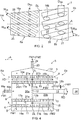
- Figure 2 shows schematically a plane figure of a blade element which is applicable to be used in the stator 6 of the refiner 1 of Figure 1 .
- Figure 2 shows a single segment-like blade element 7 which is intended to provide a part of a complete refining surface 8 of the stator 6.
- Figure 2 is intended only to exemplify possible different refining surface characteristics between the first refining zone 21a and the second refining zone 21b.
- segment-like blade element 7 for the stator 6 is disclosed in Figure 2 but the same design principles apply also to the respective blade element 10 in the rotor 9 providing the counterpart for the stator blade element 7.
- the blade element 7 of Figure 2 comprises the first end Ea facing towards the first end Ea of the stator 6 and the second end Eb facing towards the second end Eb of the stator 6, and a refining surface 8.
- the blade element 7 further comprises two different refining surface areas, i.e. a first refining surface area 8a on the side of the first end Ea and a second refining surface area 8b on the side of the second end Eb.
- the first refining surface area 8a is intended to provide the refining surface 8 of the stator 6 at the first refining zone 21a of the refiner 1
- the second refining surface area 8b is intended to provide the refining surface area 8 of the stator 6 at the second refining zone 21b of the refiner 1.
- a fictitious divisional line between the first refining surface area 8a and the second refining surface area 8b is shown in Figures 1 , 2 , 3 and 4 with a broken line denoted with the reference sign DL.
- An axial direction A of the blade segment 7 is denoted with a dot-and-dash line in Figure 2 .
- the first refining surface 8a of the blade element 7 comprises first blade bars 25 and first blade grooves 26 therebetween, as well as first openings 16a extending through the blade element 7.
- the first blade bars 25 have a blade bar width W 25 and a blade bar angle ⁇ 25 relative to the axial direction A, and the first blade grooves 26 have a blade groove width W 26 .
- the first openings 16a are round with a diameter of D 16a .
- the second refining surface area 8b of the blade element 7 comprises second blade bars 27 and second blade grooves 28 therebetween, as well as second openings 16b extending through the blade element 7.
- the second blade bars 27 have a blade bar width of W 27 and a blade bar angle ⁇ 27 relative to the axial direction A, and the second blade grooves 28 have a blade groove width W 28 .
- the second openings 16b are oval with a maximum diameter of D 16b .
- the blade bar width, the blade groove width, the blade bar angle and a shape and size of the openings on the first refining surface area 8a may be different from the blade bar width, the blade groove width, the blade bar angle and the shape and size of the openings on the second refining surface area 8b.
- the shape of the openings may for example be round, oval, triangle or any polygonal shape.
- the size of the openings may vary largely from a minimum of a fibre length to a maximum of even half of the element length.
- the openings within an element may be like holes or perforations lying in the middle part between side edges of the element but they may also be like indents or cutouts at the side edges of the element.
- the blade bar width, the blade groove width, the blade bar angle and a shape and size of the openings are some refining surface characteristics which may be varied when the refining surface characteristics are optimized for refining specific fibre material fraction with specific qualitative characteristics.
- a pitch of the refining surface i.e. a common width of a single blade bar and of the single blade groove next to the blade bar, a blade bar height and a blade groove depth may be further characteristics which may be varied when the refining surface characteristics are optimized.
- the refining zones 21a, 21b have at least one different refining surface characteristic relative to each other, it is meant that at least one of those characteristics at one refining zone 21a, 21b differs from the corresponding characteristic at the other refining zone 21a, 21b.
- the first fibre material fraction FM1 may comprise virgin hardwood fibre pulp and the second fibre material fraction FM2 may comprise virgin softwood fibre pulp.
- the first blade bar width W 25 could for example between 1 mm and 3 mm and the first blade groove width W 26 could for example be between 1 mm and 2 mm.
- the second blade bar width W 27 could for example between 3 mm and 6 mm and the second blade groove width W 28 could for example be 2 mm and 5 mm.
- the blade bars at the refining zone are set at such an angle that the blade bars promote the flow of the fibre material to be refined at the refining zone.
- the blade bars set at such an angle provide a so called pumping effect on the fibre material to be refined at the refining zone.
- This kind of blade bar angle may for example be between 10 and 30 degrees.
- an angle of crossing i.e. an angle between the blade bars in the rotor blade element and the blade bars in the stator blade element may be selected to be between 10 and 60 degrees, typically between 20 and 40 degrees.
- the number of the blade bars as well as the blade gap between the stator and the rotor may be different at different refining zones. In any case, the size of the blade gap is less than 1 mm.
- an area of a single refining zone in a blade element relative to an entire refining surface area of the blade element may vary between 10% and 90%, the rest of the entire refining surface area of the blade element being intended to be reserved for the at least one another refining zone in the blade element.
- This provides a possibility for the production of different kind of pulps.
- the area of the refining zone intended to refine hardwood fibre pulp may for example be between 70% and 80% and the area of the refining zone intended to refine softwood fibre pulp may respectively be between 20% and 30%.
- At least one of the refining zones 21a, 21b may be designed to have a very dense blade bar - blade groove -configuration, such as the configuration comprising the pitch of at most 3 mm, whereby a cutting edge length provided by the blade bars of the stator and rotor blade elements 7, 10 in the refiner 1 is very high.
- This in common with a suitably selected opening configuration in the stator and rotor blade elements 7, 10, may have an effect that the degree of grinding of the fibrous material to be refined will be very high, even as high as that at least part of the refined material has particle size properties of nanofibrillar cellulose.
- nanofibrillar cellulose refers herein to a collection of separate cellulose microfibrils or microfibril bundles derived from plant-based, and especially wood-based fibrous material. Synonyms for the nanofibrillar cellulose (NFC) are for example nanofibrillated cellulose, nanocellulose, microfibrillar cellulose, cellulose nanofiber, nano-scale cellulose, microfibrillated cellulose (MFC) or cellulose microfibcrils. Depending on the degree of grinding a particle size of the separate cellulose microfibrils or microfibril bundles is of some nanometres (nm) or micrometres ( ⁇ m).
- a mean length of the separate cellulose microfibrils or microfibril bundles may for example be 0.2 - 200 ⁇ m and a mean diameter may for example be 2 - 1000 nm.
- the pitch of the blade elements and the total open area of the openings in the blade elements may be selected in combination such that the common cutting edge length of the blade bars in the refiner is even at least 50 km per one revolution of the rotor 7.
- the process parameters may for example comprise flow rate, pressure or pressure difference, consistency, pH-value and temperature.
- the blade element of Figure 2 may also comprise between the refining surface areas 8a, 8b, for example substantially at the fictitious divisional line DL, a dam arrangement preventing the first fibre material fraction FM1 to be refined and the second fibre material fraction FM2 to be refined to mix with each other in the refining chamber 15 at a border area of the refining zones 21a, 21b, if there is any tendency to such a mixing during the operation of the refiner and the mixing is not desirable.
- the blade element of Figure 2 is intended to cover the total length of the stator 6 in the axial direction A of the refiner 1 but the blade element of Figure 2 could also be provided of two different pieces, one of them comprising the first refining surface area 8a and the other one comprising the second refining surface area 8b.
- FIG 3 shows schematically a side view of another conical refiner 2 partly in cross-section, which conical refiner 2 may be utilized to refine lignocellulose-containing wood-based fibre material.
- the conical refiner 2 of the embodiment of Figure 3 comprises a first refining zone 21a at a side of the first end Ea of the refiner 2 and a second refining zone 21b at a side of the second end Eb of the refiner 2.
- the main difference between the refiner 1 of Figure 1 and the refiner 2 of Figure 3 is that the refiner 2 comprises a solid rotor blade element 10, i.e. the rotor blade element 10 of the refiner 2 does not comprise any openings extending through the blade element 10.
- the refiner 2 of Figure 3 does not comprise any feed chamber 20a, 20b but only the first feed aggregate 18a and the first feed channel 19a at the first end Ea of the refiner 2 and the second feed aggregate 18b and the second feed channel 19b at the second end Eb of the refiner 2.
- the first fibre material fraction FM1 is to be fed into the refining chamber 15 and the first refining zone 21a therein through the first feed channel 19a and the first end Ea of the refining chamber 15.
- the second fibre material fraction FM2 is to be fed into the refining chamber 15 and the second refining zone 21b therein through the second feed channel 19b and the second end Eb of the refining chamber 15.
- the construction and operation of the refiner 2 of Figure 3 and the refining surface characteristics may be similar to those disclosed above.
- FIG 4 is a very schematic side view of a cylindrical refiner 3 partly in cross-section, which cylindrical refiner 3 may be utilized to refine lignocellulose-containing wood-based fibre material.
- the basic structure and operation of the cylindrical refiner 3 of Figure 4 is substantially similar to that of the conical refiner 1 of Figure 1 above, the main difference being the cylindrical form or shape of the stator 6 and rotor 9 instead of the conical shape. Because of this difference between the form or shape of the stator 6 and rotor 9 the size of the refining chamber 15 is adjusted in the cylindrical refiner 3 by adjusting the stator diameter, as indicated schematically with the arrow AD in Figure 4 .
- the structure and operation of the cylindrical refiner 3 of Figure 4 is self-explanatory in view of Figures 1 and 2 and the description above.
- Figure 5 shows schematically a side view of a disc refiner 4 partly in cross-section.
- the refiner 4 of Figure 5 comprises a first stationary disc-like refining element 6a, i.e. a first stator 6a, having a stator blade element 7a and a refining surface 8a therein.
- the refiner 4 further comprises a rotatable disc-like refining element 9, i.e. a rotor 9, next to the first stationary refining element 6a, the rotor 9 having a first rotor blade element 10a and a refining surface 11a therein.
- the first rotor blade element 10a and the refining surface 11a therein are directed towards the first stator 6a such that a first refining chamber 15a is formed between the opposing refining surfaces 8a, 11a of the first stator 6a and the rotor 9.
- the refiner 4 of Figure 5 further comprises a second stationary disc-like refining element 6b, i.e. a second stator 6b, having a stator blade element 7b and a refining surface 8b therein.
- the second stator 6b is arranged next to the rotor 9 on the opposite side of the rotor 9 relative to the first stator 6a such that the refining surface 8a of the stator blade element 7b in the second stator 6b is directed towards the rotor 9.
- the rotor 9 has a second rotor blade element 10b and a refining surface 11b therein.
- the second rotor blade element 10b and the refining surface 11b therein are directed towards the second stator 6b such that a second refining chamber 15b is formed between the opposing refining surfaces 8b, 11b of the second stator 6b and the rotor 9.
- the refining elements 6a, 6b, 9 and the refining surfaces 6a, 6b, 11a, 11b extend in a radial direction R of the refiner 4, the radial direction R being substantially perpendicular to the axial direction A of the refiner 4.
- the first refining chamber 15a between the first stator 6a and the rotor 9 as well as the second refining chamber 15b between the second stator 6b and the rotor 9 extend in a radial direction R of the refiner 4.
- first feed aggregate 18a and a first feed channel 19a arranged to feed a first fibre material fraction FM1 into the first refining chamber 15a through the inner edge IE of the first refining chamber 15a.
- second feed aggregate 18b and a second feed channel 19b arranged to feed a second fibre material fraction FM2 into the second refining chamber 15b through the inner edge IE of the second refining chamber 15b.
- the second fibre material fraction FM2 may be qualitatively different from the first fibre material fraction FM1 or they may be of one and same fibre material fraction.
- the refining surface characteristics of the refining surface 8a of the first stator 6a and the first refining surface 11b of the rotor 9 forming therebetween the first refining chamber 15a are selected according to the refining needs of the first fibre material fraction FM1, whereby the first refining chamber 15a provides a first refining zone 21a of the refiner 4.
- the refining surface characteristics of the refining surface 8b of the second stator 6b and the second refining surface 9b of the rotor 9 forming therebetween the second refining chamber 15b are selected according to the refining needs of the second fibre material fraction FM2, whereby the second refining chamber 15b provides a second refining zone 21b of the refiner 4. Due to the different refining needs of the qualitatively different fibre material fractions FM1, FM2 at least one refining surface characteristic in the first refining chamber 15a is different from the respective refining surface characteristic in the second refining chamber 15b.
- the first discharge chamber 22a is intended to receive the first fibre material fraction FM1 refined in the first refining chamber 15a, as shown schematically also with the arrow FM1.
- the second discharge chamber 22b is intended to receive the second fibre material fraction FM2 refined in the second refining chamber 15b, as shown schematically also with the arrow FM2.
- the refined first fibre material fraction FM1 is discharged out of the first discharge chamber 22a through a first discharge channel 23a and a first discharge aggregate 24a.
- the refined second fibre material fraction FM2 is discharged out of the second discharge chamber 22b through a second discharge channel 23b and a second discharge aggregate 24b.
- the refined first fibre material fraction FM1 and the refined second fibre material fraction FM2 are thus supplied as separate flows to a further processing.
- the number of the discharge channels is the same as the number of the refining zones, i.e. one discharge channel for each refining zone but higher number of discharge channels at some refining zone is not, however, excluded.
- the refiner of this kind is especially useful in pulp manufacturing applications with moderate volumes of different fibre material fractions to be produced, allowing utilization of different fibre material fractions with moderate number of refiners but still with optimized refining effects subjected to the specific fibre material fractions.
- the refiner 4 of Figure 5 is a double-disc refiner comprising two stators and a rotor therebetween, whereby two different refining chambers 15a, 15b are provided in the refiner. Similar type of construction may also be utilized in a conical refiner and a cylindrical refiner, whereby there are two conical or cylindrical stators and a conical or cylindrical rotor therebetween so as to provide two different refining chambers 15a, 15b, each of them providing a respective refining zone 21a, 21b with at least one different refining surface characteristic.
- This kind of refiner thus comprises a first stationary refining element and a rotatable refining element within the first stationary refining element and substantially opposite to the first stationary refining element such that a first refining chamber forming a first refining zone is formed between the opposing refining surfaces of the first stationary refining element and the rotatable refining element, as well as a second stationary refining element within the rotatable refining element and substantially opposite to the rotatable refining element such that a second refining chamber forming a second refining zone is formed between the opposing refining surfaces of the rotatable refining element and the second stationary refining element, and wherein at least one refining surface characteristic at the second refining zone is different from the respective at least one refining surface characteristic at the first refining zone.
- the first feed channel may be arranged to feed the first fibre material fraction into the first refining chamber through at least one end of the first refining chamber
- the second feed channel may be arranged to feed the second fibre material fraction into the second refining chamber through at least one end of the second refining chamber.
Landscapes
- Paper (AREA)
Abstract
Description
- The invention relates to a refiner and a method for refining lignocellulose-containing fibre material.
- In a paper and board manufacturing one or more lignocellulose-containing wood-based fibre material fractions of different quality may be mixed for manufacturing the paper or board web. The mixing of the fibre material fractions of different quality takes places for example due to a need to obtain a combination of various kind of properties in the end product, such as a specific tensile strength with a specific grammage. The fibre material fractions of different quality may include for example virgin hardwood and softwood-based fibre pulps as well as different recycled fibre materials, such as long-fibred and short-fibred pulps made of OCC (Old Corrugated Container).
- Commonly the mixed pulp is manufactured by mixing at least two fibre material fractions of different quality from separate storage tanks, each specific storage tank being reserved for the single fibre material fraction of specific quality. However, also single fibre material may contain different qualities, such as OCC that contains both long-fibred fraction and short-fibred fraction. When considering refining of the fibre material taking place before supplying the refined fibre material to the storage tank, each different fibre material fraction is refined with a refiner specifically designed for having refining surface characteristics optimized for that specific fibre material fraction. This means that each refined fibre material fraction has high quality but the number of the refiners increases with the number of different fibre material fractions to be mixed.
- The number of the refiners may be reduced by first mixing at least two fibre material fractions of different quality with each other, or having one fibre material with a large fibre length distribution, like the OCC, and thereafter refining the fibre material pulp with a single refiner. However, in this case the refining surface characteristics of the refiner are a compromise based on the refining needs of the fibre material fractions forming the pulp. Therefore, the quality of the mixed pulp after refining is not necessarily as high as the quality of the pulp formed by mixing at least two separately refined fibre material fractions as disclosed above.
- An object of the present invention is to provide a novel refiner and a method for refining lignocellulose-containing fibre material.
- The invention is characterized by the features of the independent claims.
- The idea of the invention is to simultaneously refine with a single refiner at least two flows of at least one fibre material fraction at different refining zones in the single refiner, refining surface characteristics of the different refining zones being specifically designed in view of the fibre material fraction to be refined at the refining zone as well as in view of the intended refining effect to be subjected to the fibre material fraction at the refining zone. It is thus possible to feed into the refiner at least two flows of fibre material, which two flows may be either one and same fibre material fraction or different fibre material fractions of different qualities.
- An advantage of the invention is that it is possible with a single refiner to refine simultaneously at least one fibre material fraction with different refining effects to be subjected to the at least one fibre material fraction, whereby the fibre material portions subjected to the different refining effects may for example be directed to different layers in the paper or board web to be manufactured or into different processes. The refiner of this kind is especially useful in applications wherein required amounts or volumes of different fibre material fractions for the production of the paper or board are moderate.
- Some embodiments of the invention are disclosed in the dependent claims.
- In the following the invention will be described in greater detail by means of preferred embodiments with reference to the accompanying drawings, in which
-
Figure 1 shows schematically a side view of a conical refiner partly in cross-section; -
Figure 2 shows schematically a plane figure of a blade element applicable to be used in the conical refiner ofFigure 1 ; -
Figure 3 shows schematically a side view of another conical refiner partly in cross-section; -
Figure 4 shows schematically a side view of a cylindrical refiner partly in cross-section; and -
Figure 5 shows schematically a side view of a disc refiner partly in cross-section. - For the sake of clarity, the figures show some embodiments of the invention in a simplified manner. Like reference numerals identify like elements in the figures.
-
Figure 1 is a very schematic side view of a conical refiner 1 partly in cross-section, which conical refiner 1 may be utilized to refine lignocellulose-containing wood-based fibre material. The refiner 1 has a first end Ea of smaller diameter and a second end Eb of larger diameter. - The refiner 1 comprises a
stationary refining element 6, i.e. astator 6, having a first end facing towards the first end Ea of the refiner 1 and a second end facing towards the second end Eb of the refiner 1, and therefore, for the sake of clarity, the reference sign Ea is also used to denote the first end of thestator 6 and the reference sign Eb is also used to denote the second end of thestator 6. Thestator 6 is supported to aframe structure 5 of the refiner 1. - The
stator 6 comprises a number ofstator blade elements 7 having arefining surface 8, therefining surface 8 of eachstator blade element 7 contributing to provide a complete refining surface of thestator 6. Thestator blade element 7 has a first end facing towards the first end Ea of the refiner 1 and a second end facing towards the second end Eb of the refiner 1, and therefore, for the sake of clarity, the reference sign Ea is also used to denote the first end of thestator blade element 7 and the reference sign Eb is also used to denote the second end of thestator blade element 7. - According to an embodiment of the
stator 6 it may comprise only oneblade element 7 of a conical shape and extending over a whole periphery of thestator 6 so that therefining surface 8 of this single blade element provides a complete uniform refining surface of thestator 6. According to another embodiment of thestator 6 it may comprise at least two segment-like blade elements, i.e. blade segments that are arranged adjacent to one another whereby therefining surfaces 8 of the originally separate segment-like blade elements together provide the complete uniform refining surface of thestator 6. The term blade element, when referring to thestator 6 of the refiner 1, may thus refer to a single blade element providing the complete refining surface of thestator 6 or to a blade segment providing only a part of the complete refining surface of thestator 6. For the sake of clarity, thesame reference number 8 may be used below to denote both therefining surface 8 of asingle blade element 7 for thestator 6 as well as thecomplete refining surface 8 of thestator 6. The refiningsurface 8 in thestator 6 is typically provided with blade bars and blade grooves therebetween, an embodiment of some blade bars and blade grooves being shown later inFigure 2 . - The refiner 1 further comprises a
rotatable refining element 9, i.e. arotor 9, having a first end facing towards the first end Ea of the refiner 1 and a second end facing towards the second end Eb of the refiner 1, and therefore, for the sake of clarity, the reference sign Ea is also used to denote the first end of therotor 9 and the reference sign Eb is also used to denote the second end of therotor 9. - The
rotor 9 comprises a number ofrotor blade elements 10 having arefining surface 11, therefining surface 11 of eachrotor blade element 10 contributing to provide acomplete refining surface 11 of therotor 9. Therotor blade element 10 has a first end facing towards the first end Ea of the refiner 1 and a second end facing towards the second end Eb of the refiner 1, and therefore, for the sake of clarity, the reference sign Ea is also used to denote the first end of therotor blade element 10 and the reference sign Eb is also used to denote the second end of therotor blade element 10. - According to an embodiment of the
rotor 9 it may comprise only oneblade element 10 of a conical shape and extending over a whole periphery of therotor 9 so that this single blade element provides a completeuniform refining surface 11 of therotor 9. According to another embodiment of therotor 9 it may comprise at least two segment-like blade elements, i.e. blade segments that are arranged adjacent to one another whereby therefining surfaces 11 of the originally separate segment-like blade elements together provide the complete uniform refining surface of therotor 9. The term blade element, when referring to therotor 9 of the refiner 1, may thus also refer to a single blade element providing the complete refining surface of therotor 9 or to a blade segment providing only a part of the complete refining surface of therotor 9. For the sake of clarity, thesame reference number 11 may be used below to denote therefining surface 11 of asingle blade element 9 for therotor 9 as well as thecomplete refining surface 11 of therotor 9. Therefining surface 11 in therotor 9 is also typically provided with blade bars and blade grooves therebetween, as shown later inFigure 2 . - The
rotor 9 comprises ahub 12 against which the at least onerotor blade element 10 is supported to. Thehub 12 is shown inFigure 1 , as well as inFigures 3 and4 later, highly simplified. Thehub 12 of therotor 9 is connected to ashaft 13. Theshaft 13 is connected to a highly schematically depictedmotor 14 arranged to rotate theshaft 13 and, by theshaft 13, therotor 9 for example in a rotation direction indicated with an arrow RD. - The refiner 1 may also comprise a loading device not shown in
Figure 1 for the sake of clarity, which loading device may be connected to theshaft 13 for moving therotor 9 back and forth, as indicated schematically with an arrow AD, in order to adjust a distance between thestator 6 and therotor 9, i.e. in order to adjust a size of arefining chamber 15 or ablade gap 15, forming between thestator 6 and therotor 9 or theblade elements refining chamber 15 thus forms the volume wherein the fibre material is refined. The size of therefining chamber 15 relative to the other components of the refiner is exaggerated in all the Figures. Therefining chamber 15 has a first end facing towards the first end Ea of the refiner 1 and a second end facing towards the second end Eb of the refiner 1, and therefore, for the sake of clarity, the reference sign Ea is also used to denote the first end of therefining chamber 15 and the reference sign Eb is also used to denote the second end of therefining chamber 15. - The
stator blade element 7 further comprisesopenings stator blade element 7 and therotor blade element 10 comprisesopenings rotor blade element 10, theopenings rotor blade elements stator blade element 7 and therotor blade element 10, the axial direction indicated schematically by an arrow A inFigure 1 , theopenings stator blade element 7 are substantially at same axial positions with theopenings rotor blade element 10 when theblade elements openings stator blade element 7 could be at least partly different axial positions relative to the axial positions of theopenings rotor blade element 10. - Referring back to the embodiment of
Figure 1 , the refiner 1 comprises at the first end Ea of the refiner 1 afirst feed aggregate 18a and afirst feed channel 19a connected to thefirst feed aggregate 18a, through whichfirst feed aggregate 18a and thefirst feed channel 19a a first fibre material fraction denoted schematically with an arrow FM1 is fed into afirst feed chamber 20a provided by an inner volume of therotor 9 on the side of the first end Ea of therotor 9. Thefirst feed chamber 19a extends from the first end Ea of therotor 9 towards the second end Eb of therotor 9 but not up to the second end Eb of therotor 9. - The refiner 1 further comprises at the first end Ea of the refiner 1 a
second feed aggregate 18b and asecond feed channel 19b connected to thesecond feed aggregate 18b, through whichsecond feed aggregate 18b and thesecond feed channel 19b a second fibre material fraction denoted schematically with an arrow FM2 is fed into asecond feed chamber 20b provided by an inner volume of therotor 9 on the side of the second end Eb of therotor 9. Thesecond feed chamber 19b extends from the second end Eb of therotor 9 towards the first end Ea of therotor 9 but not up to the first end Ea of therotor 9. - Furthermore, in the embodiment of
Figure 1 the refining surfaces 8, 11 in thestator 6 and therotor 9 are designed or constructed in the axial direction A of the refiner 1 such that in therefining chamber 15 there are two different refining zones with at least one different refining surface characteristic in the axial direction A of the refiner 1, i.e. afirst refining zone 21a at a side of the first end Ea of the refiner 1 and denoted with thearrow 21a and asecond refining zone 21b at a side of the second end Eb of the refiner 1 and denoted with thearrow 21b. In the axial direction A of the refiner 1, thefirst refining zone 21a is substantially at a location corresponding to thefirst feed chamber 20a of the refiner 1 and asecond refining zone 21b is substantially at a location corresponding to thesecond feed chamber 21b of the refiner 1. As shortly suggested above, at least one refining surface characteristic at thefirst refining zone 21a is selected to be different from the respective refining surface characteristic at thesecond refining zone 21b. Generally this means that the refining surface characteristics of the stator androtor blade elements first refining zone 21a are designed in view of the refining effect intended to be subjected to the first fibre material fraction FM1 to be refined at thefirst refining zone 21a and the refining surface characteristics of the stator androtor blade elements second refining zone 21b are designed in view of the refining effect intended to be subjected to the second fibre material fraction FM2 to be refined at thesecond refining zone 21b. - The operation of the refiner 1 of
Figure 1 is as follows. - The first fibre material fraction FM1 flows from the
first feed chamber 20a throughfirst openings 17a at thefirst refining zone 21a into therefining chamber 15, whereby the first fibre material fraction FM1 is refined in therefining chamber 15 substantially at thefirst refining zone 21a. Thefirst openings 17a thus connect thefirst feed chamber 20a to therefining chamber 15 at thefirst refining zone 21a. The first fibre material fraction FM1 is subjected in therefining chamber 15 at thefirst refining zone 21a to the refining effect provided by the respective refining surface areas of the stator and therotor blade elements refining chamber 15 at thefirst refining zone 21a is discharged out of therefining chamber 15 throughfirst openings 16a into adischarge chamber 22 at a background of thestator blade element 7. Thefirst openings 16a thus connect therefining chamber 15 to thedischarge chamber 22 at thefirst refining zone 21a. The flow of the first fibre material fraction FM1 into therefining chamber 15 and the flow of the refined first fibre material fraction FM1 out of therefining chamber 15 at thefirst refining zone 21a is denoted schematically also with arrows FM1. - The second fibre material fraction FM2 flows from the
second feed chamber 20b throughsecond openings 17b at thesecond refining zone 21b into therefining chamber 15, whereby the second fibre material fraction FM2 is refined in therefining chamber 15 substantially at thesecond refining zone 21b. Thesecond openings 17b thus connect thesecond feed chamber 20a to therefining chamber 15 at thesecond refining zone 21b. The second fibre material fraction FM2 is subjected in therefining chamber 15 at thesecond refining zone 21b to the refining effect provided by the respective refining surface areas of the stator and therotor blade elements refining chamber 15 at thesecond refining zone 21b is discharged out of therefining chamber 15 throughsecond openings 16b into thedischarge chamber 22. Thesecond openings 16b thus connect therefining chamber 15 to thedischarge chamber 22 at thesecond refining zone 21b. The flow of the second fibre material fraction FM2 into therefining chamber 15 and the flow of the refined first fibre material fraction FM2 out of therefining chamber 15 at thesecond refining zone 21b is denoted schematically also with arrows FM2. - In the
discharge chamber 22 the refined first fibre material fraction FM1 and the refined second fibre material fraction FM2 are combined, whereby they at least partly mix with each other. The combined flow of the refined first fibre material fraction FM1 and the refined second fibre material fraction FM2 is discharged out of the refiner 1 through adischarge channel 23 connected to thedischarge chamber 22 and further through adischarge aggregate 24 connected to thedischarge channel 23, as shown schematically with an arrow denoted with reference sign FM1+FM2. The combined flow of the refined first fibre material fraction FM1 and the refined second fibre material fraction FM2 is thus supplied as one flow to a further processing. - In the refiner 1 there are thus two
refining zones first refining zone 21a is specifically designed to refine the first fibre material fraction FM1 and thesecond refining zone 21b is specifically designed to refine the second fibre material fraction FM2. Thespecific refining zone rotor blade segments refining zones rotor blade segments first refining zone 21a with at least one different refining surface characteristic relative to the respective refining surface characteristic in thesecond refining zone 21b it is possible to provide a single refiner to refine simultaneously two fibre material flows optimally. - According to an embodiment the first fibre material fraction FM1 and the second fibre material fraction FM2 are of one and same fibre material, i.e. of the same quality. In this case different portions of the same fibre material may be subjected to different refining effects at
different refining zones - According to another embodiment the second fibre material fraction FM2 is qualitatively different from the first fibre material fraction FM1. With the definition that the second fibre material fraction FM2 is qualitatively different from the first fibre material fraction FM1 it is meant that at least one of a raw material, particle size, fibre length, freeness, residual lignin content and some other characteristic of the second fibre material fraction FM2 differs from the respective characteristic of the first fibre material fraction FM1. The
hub 12 in therotor 9 is constructed in such a way the first fibre material fraction FM1 in thefirst feed chamber 20a and the second fibre material fraction FM2 in thesecond feed chamber 20b do not mix with each other in therotor 9. - According to a further embodiment the second fibre material fraction FM2 may be the first fibre material fraction FM1 that has been refined at the
first refining zone 21a and discharged out of thefirst refining zone 21a. According to this embodiment the refiner is able to provide a two-stage refining for the first fibre material fraction FM1. -
Figure 2 shows schematically a plane figure of a blade element which is applicable to be used in thestator 6 of the refiner 1 ofFigure 1 .Figure 2 shows a single segment-like blade element 7 which is intended to provide a part of acomplete refining surface 8 of thestator 6.Figure 2 is intended only to exemplify possible different refining surface characteristics between thefirst refining zone 21a and thesecond refining zone 21b. For the sake of clarity only the segment-like blade element 7 for thestator 6 is disclosed inFigure 2 but the same design principles apply also to therespective blade element 10 in therotor 9 providing the counterpart for thestator blade element 7. - The
blade element 7 ofFigure 2 comprises the first end Ea facing towards the first end Ea of thestator 6 and the second end Eb facing towards the second end Eb of thestator 6, and arefining surface 8. Theblade element 7 further comprises two different refining surface areas, i.e. a firstrefining surface area 8a on the side of the first end Ea and a secondrefining surface area 8b on the side of the second end Eb. The firstrefining surface area 8a is intended to provide therefining surface 8 of thestator 6 at thefirst refining zone 21a of the refiner 1 and the secondrefining surface area 8b is intended to provide therefining surface area 8 of thestator 6 at thesecond refining zone 21b of the refiner 1. A fictitious divisional line between the firstrefining surface area 8a and the secondrefining surface area 8b is shown inFigures 1 ,2 ,3 and4 with a broken line denoted with the reference sign DL. An axial direction A of theblade segment 7 is denoted with a dot-and-dash line inFigure 2 . - The
first refining surface 8a of theblade element 7 comprises first blade bars 25 andfirst blade grooves 26 therebetween, as well asfirst openings 16a extending through theblade element 7. The first blade bars 25 have a blade bar width W25 and a blade bar angle α25 relative to the axial direction A, and thefirst blade grooves 26 have a blade groove width W26. Thefirst openings 16a are round with a diameter of D16a. The secondrefining surface area 8b of theblade element 7 comprises second blade bars 27 andsecond blade grooves 28 therebetween, as well assecond openings 16b extending through theblade element 7. The second blade bars 27 have a blade bar width of W27 and a blade bar angle α27 relative to the axial direction A, and thesecond blade grooves 28 have a blade groove width W28. Thesecond openings 16b are oval with a maximum diameter of D16b. In the schematic example ofFigure 2 it can be seen that the blade bar width, the blade groove width, the blade bar angle and a shape and size of the openings on the firstrefining surface area 8a may be different from the blade bar width, the blade groove width, the blade bar angle and the shape and size of the openings on the secondrefining surface area 8b. The shape of the openings may for example be round, oval, triangle or any polygonal shape. The size of the openings may vary largely from a minimum of a fibre length to a maximum of even half of the element length. The openings within an element may be like holes or perforations lying in the middle part between side edges of the element but they may also be like indents or cutouts at the side edges of the element. - The blade bar width, the blade groove width, the blade bar angle and a shape and size of the openings are some refining surface characteristics which may be varied when the refining surface characteristics are optimized for refining specific fibre material fraction with specific qualitative characteristics. A pitch of the refining surface, i.e. a common width of a single blade bar and of the single blade groove next to the blade bar, a blade bar height and a blade groove depth may be further characteristics which may be varied when the refining surface characteristics are optimized. When it is said above that the
refining zones refining zone other refining zone - According to an embodiment the first fibre material fraction FM1 may comprise virgin hardwood fibre pulp and the second fibre material fraction FM2 may comprise virgin softwood fibre pulp. In that case, on the
first refining area 8a of theblade element 7, i.e. on thefirst refining zone 21a of the refiner 1, the first blade bar width W25 could for example between 1 mm and 3 mm and the first blade groove width W26 could for example be between 1 mm and 2 mm. On the secondrefining surface area 8b of theblade element 7, i.e. on thesecond refining zone 21b of the refiner 1, the second blade bar width W27 could for example between 3 mm and 6 mm and the second blade groove width W28 could for example be 2 mm and 5 mm. - The blade bars at the refining zone are set at such an angle that the blade bars promote the flow of the fibre material to be refined at the refining zone. In other words the blade bars set at such an angle provide a so called pumping effect on the fibre material to be refined at the refining zone. This kind of blade bar angle may for example be between 10 and 30 degrees. On the other hand, an angle of crossing, i.e. an angle between the blade bars in the rotor blade element and the blade bars in the stator blade element may be selected to be between 10 and 60 degrees, typically between 20 and 40 degrees.
- In addition to the refining surface characteristics listed above, also the number of the blade bars as well as the blade gap between the stator and the rotor may be different at different refining zones. In any case, the size of the blade gap is less than 1 mm.
- Furthermore, an area of a single refining zone in a blade element relative to an entire refining surface area of the blade element may vary between 10% and 90%, the rest of the entire refining surface area of the blade element being intended to be reserved for the at least one another refining zone in the blade element. This provides a possibility for the production of different kind of pulps. For example, when refining simultaneously the hardwood fibre pulp at one refining zone and the softwood fibre pulp at the other refining zone, the area of the refining zone intended to refine hardwood fibre pulp may for example be between 70% and 80% and the area of the refining zone intended to refine softwood fibre pulp may respectively be between 20% and 30%.
- According to a further embodiment at least one of the
refining zones rotor blade elements rotor blade elements rotor 7. - Furthermore, there may be different process parameters utilized at
different refining zones - The blade element of
Figure 2 may also comprise between therefining surface areas refining chamber 15 at a border area of therefining zones - The blade element of
Figure 2 is intended to cover the total length of thestator 6 in the axial direction A of the refiner 1 but the blade element ofFigure 2 could also be provided of two different pieces, one of them comprising the firstrefining surface area 8a and the other one comprising the secondrefining surface area 8b. -
Figure 3 shows schematically a side view of another conical refiner 2 partly in cross-section, which conical refiner 2 may be utilized to refine lignocellulose-containing wood-based fibre material. Correspondingly to the conical refiner 1 of the embodiment ofFigure 1 , the conical refiner 2 of the embodiment ofFigure 3 comprises afirst refining zone 21a at a side of the first end Ea of the refiner 2 and asecond refining zone 21b at a side of the second end Eb of the refiner 2. The main difference between the refiner 1 ofFigure 1 and the refiner 2 ofFigure 3 is that the refiner 2 comprises a solidrotor blade element 10, i.e. therotor blade element 10 of the refiner 2 does not comprise any openings extending through theblade element 10. As a consequence of that the refiner 2 ofFigure 3 does not comprise anyfeed chamber first feed aggregate 18a and thefirst feed channel 19a at the first end Ea of the refiner 2 and thesecond feed aggregate 18b and thesecond feed channel 19b at the second end Eb of the refiner 2. The first fibre material fraction FM1 is to be fed into therefining chamber 15 and thefirst refining zone 21a therein through thefirst feed channel 19a and the first end Ea of therefining chamber 15. The second fibre material fraction FM2 is to be fed into therefining chamber 15 and thesecond refining zone 21b therein through thesecond feed channel 19b and the second end Eb of therefining chamber 15. Otherwise the construction and operation of the refiner 2 ofFigure 3 and the refining surface characteristics may be similar to those disclosed above. -
Figure 4 is a very schematic side view of acylindrical refiner 3 partly in cross-section, whichcylindrical refiner 3 may be utilized to refine lignocellulose-containing wood-based fibre material. The basic structure and operation of thecylindrical refiner 3 ofFigure 4 is substantially similar to that of the conical refiner 1 ofFigure 1 above, the main difference being the cylindrical form or shape of thestator 6 androtor 9 instead of the conical shape. Because of this difference between the form or shape of thestator 6 androtor 9 the size of therefining chamber 15 is adjusted in thecylindrical refiner 3 by adjusting the stator diameter, as indicated schematically with the arrow AD inFigure 4 . The structure and operation of thecylindrical refiner 3 ofFigure 4 is self-explanatory in view ofFigures 1 and2 and the description above. - In the
refiners 1, 3 ofFigures 1 ,4 there are twodifferent refining zones refiners 1, 3 like inFigures 1 and4 may be increased by increasing a number of the feed channels for the separate fibre material fraction flows. -
Figure 5 shows schematically a side view of a disc refiner 4 partly in cross-section. The refiner 4 ofFigure 5 comprises a first stationary disc-like refining element 6a, i.e. a first stator 6a, having a stator blade element 7a and arefining surface 8a therein. The refiner 4 further comprises a rotatable disc-like refining element 9, i.e. arotor 9, next to the first stationary refining element 6a, therotor 9 having a firstrotor blade element 10a and arefining surface 11a therein. The firstrotor blade element 10a and therefining surface 11a therein are directed towards the first stator 6a such that afirst refining chamber 15a is formed between the opposingrefining surfaces rotor 9. - The refiner 4 of
Figure 5 further comprises a second stationary disc-like refining element 6b, i.e. asecond stator 6b, having astator blade element 7b and arefining surface 8b therein. Thesecond stator 6b is arranged next to therotor 9 on the opposite side of therotor 9 relative to the first stator 6a such that therefining surface 8a of thestator blade element 7b in thesecond stator 6b is directed towards therotor 9. Therotor 9 has a secondrotor blade element 10b and arefining surface 11b therein. The secondrotor blade element 10b and therefining surface 11b therein are directed towards thesecond stator 6b such that asecond refining chamber 15b is formed between the opposingrefining surfaces second stator 6b and therotor 9. - In the disc-like refiner 4 the
refining elements refining surfaces first refining chamber 15a between the first stator 6a and therotor 9 as well as thesecond refining chamber 15b between thesecond stator 6b and therotor 9 extend in a radial direction R of the refiner 4. In the radial direction R of the refiner 4 thestators 6a, 6b and therotor 9, and therefining chambers refining elements refining chambers - Further in the refiner 4 of
Figure 5 there is afirst feed aggregate 18a and afirst feed channel 19a arranged to feed a first fibre material fraction FM1 into thefirst refining chamber 15a through the inner edge IE of thefirst refining chamber 15a. Further there is asecond feed aggregate 18b and asecond feed channel 19b arranged to feed a second fibre material fraction FM2 into thesecond refining chamber 15b through the inner edge IE of thesecond refining chamber 15b. The second fibre material fraction FM2 may be qualitatively different from the first fibre material fraction FM1 or they may be of one and same fibre material fraction. The refining surface characteristics of therefining surface 8a of the first stator 6a and thefirst refining surface 11b of therotor 9 forming therebetween thefirst refining chamber 15a are selected according to the refining needs of the first fibre material fraction FM1, whereby thefirst refining chamber 15a provides afirst refining zone 21a of the refiner 4. The refining surface characteristics of therefining surface 8b of thesecond stator 6b and the second refining surface 9b of therotor 9 forming therebetween thesecond refining chamber 15b are selected according to the refining needs of the second fibre material fraction FM2, whereby thesecond refining chamber 15b provides asecond refining zone 21b of the refiner 4. Due to the different refining needs of the qualitatively different fibre material fractions FM1, FM2 at least one refining surface characteristic in thefirst refining chamber 15a is different from the respective refining surface characteristic in thesecond refining chamber 15b. - Further in the refiner 4 of
Figure 5 there are twoseparate discharge chambers first discharge chamber 22a is intended to receive the first fibre material fraction FM1 refined in thefirst refining chamber 15a, as shown schematically also with the arrow FM1. Thesecond discharge chamber 22b is intended to receive the second fibre material fraction FM2 refined in thesecond refining chamber 15b, as shown schematically also with the arrow FM2. The refined first fibre material fraction FM1 is discharged out of thefirst discharge chamber 22a through afirst discharge channel 23a and afirst discharge aggregate 24a. The refined second fibre material fraction FM2 is discharged out of thesecond discharge chamber 22b through asecond discharge channel 23b and asecond discharge aggregate 24b. The refined first fibre material fraction FM1 and the refined second fibre material fraction FM2 are thus supplied as separate flows to a further processing. - In the refiner of
Figure 5 there is thus adischarge channel refining zone different refining zones - In the refiner 4 of
Figure 5 , instead of theseparate discharge chambers separate discharge channels separate discharge aggregates common discharge chamber 22, onecommon discharge channel 23 and onecommon discharge aggregate 24 could be utilized. Correspondingly, in therefiners 1, 2, 3 ofFigures 1 ,3 ,4 could also be utilizedseparate discharge chambers separate discharge channels separate discharge aggregates common discharge chamber 22, onecommon discharge channel 23 and onecommon discharge aggregate 24. - The refiner 4 of
Figure 5 is a double-disc refiner comprising two stators and a rotor therebetween, whereby twodifferent refining chambers different refining chambers respective refining zone Figure 5 , may further be increased by increasing the number of stators and rotors in the refiner. - It will be obvious to a person skilled in the art that, as the technology advances, the inventive concept can be implemented in various ways. The invention and its embodiments are not limited to the examples described above but may vary within the scope of the claims.
Claims (14)
- A refiner (1, 2, 3, 4) for refining lignocellulose-containing fibre material, the refiner (1, 2, 3, 4) comprising
at least two substantially oppositely positioned refining elements (6, 6a, 6b, 9) each of them comprising at least one refining surface (8, 8a, 8b, 11, 11a, 11b) with blade bars (25, 27) and blade grooves (26, 28), the refining surfaces (8, 8a, 8b, 11, 11a, 11b) of two substantially oppositely positioned refining elements (6, 6a, 6b, 9) facing towards each other and forming between them a refining chamber (15, 15a, 15b) receiving fibre material to be refined,
at least two feed channels (19a, 19b) for feeding into the refiner (1, 2, 3, 4) at least one fibre material fraction (FM1, FM2) to be refined,
at least two refining zones (21a, 21b) with at least one different refining surface characteristic between the refining zones (21a, 21b), each refining zone (21a, 21b) intended to refine one fibre material fraction (FM1, FM2) of the at least one fibre material fraction (FM1, FM2), and
a discharge channel (23a, 23b) respective to the refining zone (21a, 21b) for discharging fibre material fractions (FM1, FM2) refined at the refining zones (21a, 21b) out of the refiner (1, 2, 3, 4) as separate flows. - A refiner as claimed in claim 1, characterized in that the refiner (1, 2, 3, 4) comprises
a first feed channel (19a) for feeding into the refiner (1, 2, 3, 4) a first fibre material fraction (FM1),
a second feed channel (19b) for feeding into the refiner (1, 2, 3, 4) a second fibre material fraction (FM2), and
a first refining zone (21a) for refining the first fibre material fraction (FM1) and a second refining zone (21b) for refining the second fibre material fraction (FM2). - A refiner as claimed in claim 2, characterized in that the refiner (1, 2, 3) comprises a stationary refining element (6) and a rotatable refining element (9) within the stationary refining element (6) and substantially opposite to the stationary refining element (6) such that a refining chamber (15) is formed between the opposing refining surfaces (8, 11) of the refining elements (6, 9), and wherein the refiner (1, 2, 3), the refining elements (6, 9) and the refining chamber (15) have an axial direction (A) and in the axial direction (A) a first end (Ea) and a second end (Eb) opposite to the first end (Ea), and that
in the axial direction (A) of the refining chamber (15) there are at the first end (Ea) of the refining chamber (15a) a first refining zone (21a) extending towards the second end (Eb) of the refining chamber (15) for refining a first fibre material fraction (FM1) and at the second end (Eb) of the refining chamber (15) a second refining zone (21b) extending towards the first end (Ea) of the refining chamber (15) for refining a second fibre material fraction (FM2), the second refining zone (21b) having at least one different refining surface characteristic relative to the first refining zone (21a). - A refiner as claimed in claims 2 and 3, characterized in that
the first feed channel (19a) is arranged to feed the first fibre material fraction (FM1) into the first refining zone (21a) through the first end (Ea) of the refining chamber (15),
the second feed channel (19b) is arranged to feed the second fibre material fraction (FM2) into the second refining zone (21b) through the second end (Eb) of the refining chamber (15), and that
the stationary refining element (6) comprises at each refining zone (21a, 21b) at least one opening (16a, 16b) allowing the fibre material (FM1, FM2) refined at the respective refining zone (20a, 20b) to discharge out of the refining chamber (15) through the respective at least one opening (16a, 16b). - A refiner as claimed in claims 2 and 3, characterized in that
the first feed channel (19a) is arranged to feed the first fibre material fraction (FM1) into an inner volume of the rotatable refining element (9) through the first end (Ea) of the rotatable refining element (9),
the second feed channel (19b) is arranged to feed the second fibre material fraction (FM2) into an inner volume of the rotatable refining element (9) through the second end (Eb) of the rotatable refining element (9), and that
the rotatable refining element (9) comprises at each refining zone (21a, 21b) at least one opening (17a, 17b) allowing the fibre material fraction (FM1, FM2) to be refined at the respective refining zone (21a, 21b) to be fed into the refining chamber (15) at the respective refining zone (21a, 21b) through the respective at least one opening (17a, 17b) and
the stationary refining element (6) comprises at each refining zone (21a, 21b) at least one opening (16a, 16b) allowing the fibre material fraction (FM1, FM2) refined at the respective refining zone (21a, 21b) to discharge out of the refining chamber (15) at the respective refining zone (21a, 21b) through the respective at least one opening (16, 16b). - A refiner as claimed in claim 2, characterized in that the refiner comprises a first stationary refining element and a rotatable refining element (9) within the first stationary refining element and substantially opposite to the first stationary refining element such that a first refining chamber (15a) forming a first refining zone (21a) is formed between the opposing refining surfaces of the first stationary refining element and the rotatable refining element (9), and a second stationary refining element within the rotatable refining element (9) and substantially opposite to the rotatable refining element (9) such that a second refining chamber (15b) forming a second refining zone (21b) is formed between the opposing refining surfaces of the rotatable refining element (9) and the second stationary refining element, wherein at least one refining surface characteristic at the second refining zone (21b) is different from the respective at least one refining surface characteristic at the first refining zone (21a), and wherein
the refiner, the refining elements and the refining chambers have an axial direction (A) and in the axial direction (A) a first end (Ea) and a second end (Eb) opposite to the first end (Eb), and that
the first feed channel (19a) is arranged to feed the first fibre material fraction (FM1) into the first refining chamber (15a) through at least one end (Ea, Eb) of the first refining chamber (15a), and
the second feed channel (19b) is arranged to feed the second fibre material fraction (FM2) into the second refining chamber (15b) through at least one end (Ea, Eb) of the second refining chamber (15b). - A refiner as claimed in any one of the preceding claims, characterized in that the refiner is a conical refiner (1, 2) with conical refining elements (6, 9) having a first end (Ea) of smaller diameter and a second end (Eb) of larger diameter.
- A refiner as claimed in claim 1 or 2, characterized in that the refiner (4) comprises
a first stationary disc-like refining element (6a) and a rotatable disc-like refining element (9) next to the first stationary refining element (6a) and substantially opposite to the first stationary refining element (6a) such that a first refining chamber (15a) forming a first refining zone (21a) is formed between the opposing refining surfaces (8a, 11a) of the first stationary refining element (6a) and the rotatable refining element (9),
a second disc-like stationary refining element (6b) next to the rotatable refining element (9) on the opposite side of the rotatable refining element (9) relative to the first stationary refining element (6a), the second stationary refining element (6b) being substantially opposite to the rotatable refining element (9) such that a second refining chamber (15b) forming a second refining zone (21b) is formed between the opposing refining surfaces (8b, 11b) of the rotatable refining element (9) and the second stationary refining element (6b), wherein at least one refining surface characteristic at the second refining zone (21b) is different from the respective at least one refining surface characteristic at the first refining zone (21a), and wherein
the first feed channel (19a) is arranged to feed the first fibre material fraction (FM1) into the first refining chamber (15a) and the second feed channel (19b) is arranged to feed the second fibre material fraction (FM2) into the second refining chamber (FM2). - A refiner as claimed in any one of claims 2 to 8, characterized in that the refiner (1, 2, 3, 4) comprises
a first discharge channel (23a) for discharging out of the refiner (1, 2, 3, 4) the first fibre material fraction (FM1) refined at the first refining zone (21a) and
a second discharge channel (23b) for discharging out of the refiner (1, 2, 3, 4) the second fibre material fraction (FM2) refined at the second refining zone (21b). - A refiner as claimed in any one of the preceding claims, characterized in that the refining surface characteristic is at least one of the following: a blade bar width, a blade groove width, a blade bar angle, a blade bar height, a blade groove depth, a shape of an opening and a size of an opening.
- A method for refining lignocellulose-containing fibre material with a refiner (1, 2, 3, 4) comprising at least two substantially oppositely positioned refining elements (6, 6a, 6b, 9), the method comprising
feeding into the refiner (1, 2, 3, 4) at least two flows of at least one fibre material fraction (FM1, FM2) to be refined,
subjecting the at least two flows of the at least one fibre material fraction (FM1, FM2) to different refining effects in the refiner (1, 2, 3, 4), and
discharging fibre material fraction flows subjected to different refining effects out of the refiner (1, 2, 3, 4) as separate flows. - A method as claimed in claim 11, wherein the refiner (1, 2, 3, 4) comprises a stationary refining element (6) and a rotatable refining element (9) within the stationary refining element (6) and substantially opposite to the stationary refining element (6) such that a refining chamber (15) is formed between the opposing refining surfaces (8, 11) of the refining elements (6, 9), and wherein the refiner (1, 2, 3), the refining elements (6,9) and the refining chamber (15) have an axial direction (A) and in the axial direction (A) a first end (Ea) and a second end (Eb) opposite to the first end (Ea), and that
in the axial direction (A) of the refining chamber (15) there are at the first end (Ea) of the refining chamber (15) a first refining zone (21a) extending towards the second end (Eb) of the refining chamber (15) for refining a first fibre material fraction (FM1) and at the second end (Eb) of the refining chamber (15) a second refining zone (21b) extending towards the first end (Ea) of the refining chamber (15) for refining a second fibre material fraction (FM2), the second refining zone (21b) having at least one different refining surface characteristic relative to the first refining zone (21a), whereby
a first fibre material fraction (FM1) to be refined is fed into the first refining zone (21a),
a second fibre material fraction (FM2) to be refined is fed into the second refining zone (21b),
the first fibre material fraction (FM1) refined at the first refining zone (21a) is discharged out of the refining chamber (15) at the first refining zone (21a) through at least one opening (16a) arranged in the stationary refining element (6) at the first refining zone (21a), and
the second fibre material fraction (FM2) refined at the second refining zone (21b) is discharged out of the refining chamber (15) at the second refining zone (21b) through at least one opening (16b) arranged in the stationary refining element (6) at the second refining zone (21b). - A method as claimed in claim 12, wherein
the first fibre material fraction (FM1) to be refined is fed into an inner volume of the rotatable refining element (9) through the first end (Ea) of the rotatable refining element (9) and into the refining chamber (15) at the first refining zone (21a) through at least one opening (17a) arranged in the rotatable refining element (6) at the first refining zone (21a) and
the second fibre material fraction (FM2) to be refined is fed into an inner volume of the rotatable refining element (9) through the second end (Eb) of the rotatable refining element (9) and into the refining chamber (15) at the second refining zone (21b) through at least one opening (17b) arranged in the rotatable refining element (9) at the second refining zone (21b). - A method as claimed in claim 12 or 13, wherein the second fibre material fraction (FM2) is qualitatively different from the first fibre material fraction (FM1).
Applications Claiming Priority (1)
| Application Number | Priority Date | Filing Date | Title |
|---|---|---|---|
| FI20195865A FI129596B (en) | 2019-10-10 | 2019-10-10 | Refiner |
Publications (1)
| Publication Number | Publication Date |
|---|---|
| EP3805452A1 true EP3805452A1 (en) | 2021-04-14 |
Family
ID=72665145
Family Applications (1)
| Application Number | Title | Priority Date | Filing Date |
|---|---|---|---|
| EP20198743.5A Pending EP3805452A1 (en) | 2019-10-10 | 2020-09-28 | Refiner |
Country Status (5)
| Country | Link |
|---|---|
| US (1) | US20210108367A1 (en) |
| EP (1) | EP3805452A1 (en) |
| JP (1) | JP7601315B2 (en) |
| CN (1) | CN112647335B (en) |
| FI (1) | FI129596B (en) |
Families Citing this family (1)
| Publication number | Priority date | Publication date | Assignee | Title |
|---|---|---|---|---|
| US20220333303A1 (en) * | 2021-04-16 | 2022-10-20 | Andritz Inc. | Flow-altering refiner segment |
Citations (3)
| Publication number | Priority date | Publication date | Assignee | Title |
|---|---|---|---|---|
| WO2000050688A1 (en) * | 1999-02-26 | 2000-08-31 | Andritz Inc. | High pressure, high-speed primary and secondary refining |
| EP3103916A1 (en) * | 2015-06-10 | 2016-12-14 | Aikawa Iron Works Co., Ltd. | Refiner beating method and refiner |
| US20190078259A1 (en) * | 2017-09-11 | 2019-03-14 | International Paper Company | Method for processing wood fibers |
Family Cites Families (3)
| Publication number | Priority date | Publication date | Assignee | Title |
|---|---|---|---|---|
| US2900141A (en) * | 1956-05-21 | 1959-08-18 | Vidas Charles | Jordan |
| FI124393B (en) * | 2008-06-19 | 2014-08-15 | Valmet Technologies Inc | Refiner and process for grinding fibrous material and steel segments into a refiner for grinding fibrous material |
| FI121963B (en) | 2009-07-03 | 2011-06-30 | Metso Paper Inc | refiner |
-
2019
- 2019-10-10 FI FI20195865A patent/FI129596B/en active IP Right Grant
-
2020
- 2020-09-28 EP EP20198743.5A patent/EP3805452A1/en active Pending
- 2020-10-07 JP JP2020169600A patent/JP7601315B2/en active Active
- 2020-10-09 US US17/067,542 patent/US20210108367A1/en not_active Abandoned
- 2020-10-09 CN CN202011071527.5A patent/CN112647335B/en active Active
Patent Citations (3)
| Publication number | Priority date | Publication date | Assignee | Title |
|---|---|---|---|---|
| WO2000050688A1 (en) * | 1999-02-26 | 2000-08-31 | Andritz Inc. | High pressure, high-speed primary and secondary refining |
| EP3103916A1 (en) * | 2015-06-10 | 2016-12-14 | Aikawa Iron Works Co., Ltd. | Refiner beating method and refiner |
| US20190078259A1 (en) * | 2017-09-11 | 2019-03-14 | International Paper Company | Method for processing wood fibers |
Also Published As
| Publication number | Publication date |
|---|---|
| CN112647335B (en) | 2023-05-02 |
| FI129596B (en) | 2022-05-13 |
| CN112647335A (en) | 2021-04-13 |
| US20210108367A1 (en) | 2021-04-15 |
| JP2021063329A (en) | 2021-04-22 |
| FI20195865A1 (en) | 2021-04-11 |
| JP7601315B2 (en) | 2024-12-17 |
Similar Documents
| Publication | Publication Date | Title |
|---|---|---|
| US7758726B2 (en) | Disc refiner with increased gap between fiberizing and fibrillating bands | |
| US7300540B2 (en) | Energy efficient TMP refining of destructured chips | |
| JPH06240592A (en) | Segment for beating | |
| US11891758B2 (en) | Refiner blade element | |
| US5112443A (en) | Method and apparatus for the manufacture of fibre pulp | |
| CN113445347B (en) | Method and apparatus for producing nanofibrillated cellulose | |
| EP3805452A1 (en) | Refiner | |
| EP2960367B1 (en) | Single-disc refiner | |
| US20230183921A1 (en) | Blade Element for Refiner | |
| US20230250588A1 (en) | Containerboard products incorporating surface enhanced pulp fibers and making the same | |
| US20240263395A1 (en) | Refining Segment | |
| CA2629272A1 (en) | Refiner with spiral inlet and dual tangential discharge outlet | |
| CA1306378C (en) | Method for decreasing energy consumption during refining of fiber material while maintaining capacity | |
| KR20230020412A (en) | Blade segments for refiners |
Legal Events
| Date | Code | Title | Description |
|---|---|---|---|
| PUAI | Public reference made under article 153(3) epc to a published international application that has entered the european phase |
Free format text: ORIGINAL CODE: 0009012 |
|
| STAA | Information on the status of an ep patent application or granted ep patent |
Free format text: STATUS: THE APPLICATION HAS BEEN PUBLISHED |
|
| AK | Designated contracting states |
Kind code of ref document: A1 Designated state(s): AL AT BE BG CH CY CZ DE DK EE ES FI FR GB GR HR HU IE IS IT LI LT LU LV MC MK MT NL NO PL PT RO RS SE SI SK SM TR |
|
| AX | Request for extension of the european patent |
Extension state: BA ME |
|
| STAA | Information on the status of an ep patent application or granted ep patent |
Free format text: STATUS: REQUEST FOR EXAMINATION WAS MADE |
|
| 17P | Request for examination filed |
Effective date: 20211008 |
|
| RBV | Designated contracting states (corrected) |
Designated state(s): AL AT BE BG CH CY CZ DE DK EE ES FI FR GB GR HR HU IE IS IT LI LT LU LV MC MK MT NL NO PL PT RO RS SE SI SK SM TR |
|
| STAA | Information on the status of an ep patent application or granted ep patent |
Free format text: STATUS: EXAMINATION IS IN PROGRESS |
|
| 17Q | First examination report despatched |
Effective date: 20241107 |