EP3805359A1 - Sample analysis assisting apparatus - Google Patents
Sample analysis assisting apparatus Download PDFInfo
- Publication number
- EP3805359A1 EP3805359A1 EP19814438.8A EP19814438A EP3805359A1 EP 3805359 A1 EP3805359 A1 EP 3805359A1 EP 19814438 A EP19814438 A EP 19814438A EP 3805359 A1 EP3805359 A1 EP 3805359A1
- Authority
- EP
- European Patent Office
- Prior art keywords
- sample
- tip
- operation unit
- substance
- region
- Prior art date
- Legal status (The legal status is an assumption and is not a legal conclusion. Google has not performed a legal analysis and makes no representation as to the accuracy of the status listed.)
- Granted
Links
Images




Classifications
-
- G—PHYSICS
- G01—MEASURING; TESTING
- G01N—INVESTIGATING OR ANALYSING MATERIALS BY DETERMINING THEIR CHEMICAL OR PHYSICAL PROPERTIES
- G01N35/00—Automatic analysis not limited to methods or materials provided for in any single one of groups G01N1/00 - G01N33/00; Handling materials therefor
- G01N35/10—Devices for transferring samples or any liquids to, in, or from, the analysis apparatus, e.g. suction devices, injection devices
- G01N35/1065—Multiple transfer devices
- G01N35/1072—Multiple transfer devices with provision for selective pipetting of individual channels
-
- G—PHYSICS
- G01—MEASURING; TESTING
- G01N—INVESTIGATING OR ANALYSING MATERIALS BY DETERMINING THEIR CHEMICAL OR PHYSICAL PROPERTIES
- G01N35/00—Automatic analysis not limited to methods or materials provided for in any single one of groups G01N1/00 - G01N33/00; Handling materials therefor
- G01N35/10—Devices for transferring samples or any liquids to, in, or from, the analysis apparatus, e.g. suction devices, injection devices
- G01N35/1081—Devices for transferring samples or any liquids to, in, or from, the analysis apparatus, e.g. suction devices, injection devices characterised by the means for relatively moving the transfer device and the containers in an horizontal plane
- G01N35/109—Devices for transferring samples or any liquids to, in, or from, the analysis apparatus, e.g. suction devices, injection devices characterised by the means for relatively moving the transfer device and the containers in an horizontal plane with two horizontal degrees of freedom
-
- G—PHYSICS
- G01—MEASURING; TESTING
- G01N—INVESTIGATING OR ANALYSING MATERIALS BY DETERMINING THEIR CHEMICAL OR PHYSICAL PROPERTIES
- G01N35/00—Automatic analysis not limited to methods or materials provided for in any single one of groups G01N1/00 - G01N33/00; Handling materials therefor
- G01N35/10—Devices for transferring samples or any liquids to, in, or from, the analysis apparatus, e.g. suction devices, injection devices
- G01N2035/1027—General features of the devices
- G01N2035/103—General features of the devices using disposable tips
-
- G—PHYSICS
- G01—MEASURING; TESTING
- G01N—INVESTIGATING OR ANALYSING MATERIALS BY DETERMINING THEIR CHEMICAL OR PHYSICAL PROPERTIES
- G01N35/00—Automatic analysis not limited to methods or materials provided for in any single one of groups G01N1/00 - G01N33/00; Handling materials therefor
- G01N35/10—Devices for transferring samples or any liquids to, in, or from, the analysis apparatus, e.g. suction devices, injection devices
- G01N2035/1027—General features of the devices
- G01N2035/1034—Transferring microquantities of liquid
-
- G—PHYSICS
- G01—MEASURING; TESTING
- G01N—INVESTIGATING OR ANALYSING MATERIALS BY DETERMINING THEIR CHEMICAL OR PHYSICAL PROPERTIES
- G01N35/00—Automatic analysis not limited to methods or materials provided for in any single one of groups G01N1/00 - G01N33/00; Handling materials therefor
- G01N35/10—Devices for transferring samples or any liquids to, in, or from, the analysis apparatus, e.g. suction devices, injection devices
- G01N35/1065—Multiple transfer devices
- G01N2035/1076—Multiple transfer devices plurality or independently movable heads
Definitions
- the present disclosure relates to a sample analysis support apparatus.
- a substance serving as a potential drug such as a compound
- a sample such as cells, which are the basic constituent element of living organisms.
- the sample is collected after the sample reacts with the substance.
- patent literature (PTL) 1 discloses an apparatus that automatically performs operations for collecting the sample at a tip, such as a nanospray tip.
- PTL 2 discloses a technique for highly accurate positioning control of the tip in the apparatus.
- PTL 3 discloses a technique for using a nanopipette to administer a substance, such as a compound, to a sample, such as cells.
- the apparatuses disclosed in PTL 1 and 2 include a sample region where a sample is placed, a tip region where a tip is placed, and an operation unit to which the tip is attachable and detachable and which is capable of operations such as collecting the sample with the tip.
- the apparatus disclosed in PTL 1 and 2 only includes one operation unit, however, and therefore has room for improvement in terms of throughput and range of applications.
- a sample analysis support apparatus includes a sample region in which a sample is to be disposed; a tip region in which a tip is to be disposed; a first operation unit capable of an operation on the sample using the tip, the tip being attachable to and detachable from the first operation unit; a second operation unit capable of an operation on the sample using the tip, the tip being attachable to and detachable from the second operation unit; a transport unit configured to support each of the first operation unit and the second operation unit moveably between the tip region and the sample region; and a movement controller capable of controlling the transport unit to move each of the first operation unit and the second operation unit between the tip region and the sample region.
- the operation on the sample by the first operation unit may include collection of the sample and/or provision of a substance to the sample
- the operation on the sample by the second operation unit may include collection of the sample and/or provision of a substance to the sample.
- the tip may include an end opening, located at an end of the tip, to enable collection of the sample and/or provision of a substance to the sample. This configuration enables the sample to be collected and/or a substance to be provided to the sample through the end opening precisely.
- the operation on the sample by the first operation unit may include collection of the sample
- the operation on the sample by the second operation unit may include collection of the sample.
- the tip may include a first tip attachable to and detachable from the first operation unit and a second tip attachable to and detachable from the second operation unit, and the end opening of the first tip and the end opening of the second tip may be equivalent in size.
- this configuration can shorten the transportation time of the collected sample and improve throughput.
- the tip may include a first tip attachable to and detachable from the first operation unit and a second tip attachable to and detachable from the second operation unit, and the end opening of the first tip may be smaller than the end opening of the second tip.
- the operation on the sample by the first operation unit may include collection of an intracellular substance of a specific cell
- the operation on the sample by the second operation unit may include collection of the specific cell
- the operation on the sample by the first operation unit may include provision of a substance to the sample, and the operation on the sample by the second operation unit may include collection of the sample.
- This configuration enables collection of the sample to which a substance has been provided, thereby broadening the range of applications.
- the operation on the sample by the first operation unit may include provision of a substance to a specific cell
- the operation on the sample by the second operation unit may include collection of the specific cell, an intracellular substance of the specific cell, or a cell close to the specific cell. This configuration enables observation of the effect of providing a substance to a specific cell.
- the sample region may include a predetermined operation position where the operation on the sample by the first operation unit and the operation on the sample by the second operation unit are performed alternatively.
- the movement controller may be capable of attaching the first tip onto the first operation unit in the tip region, moving the first operation unit from the tip region to the sample region, performing the operation on the sample using the first tip in the sample region, and moving the first operation unit from the sample region to the tip region
- the movement controller may be capable of attaching the second tip onto the second operation unit in the tip region, moving the second operation unit from the tip region to the sample region, performing the operation on the sample using the second tip in the sample region, and moving the second operation unit from the sample region to the tip region.
- the transport unit may be a transport stage used by both the first operation unit and the second operation unit. This configuration enables a reduction in space and in cost.
- the transportation stage may include a z-direction support configured to support the first operation unit movably in a z-direction, which is the vertical direction, a z-direction guide capable of guiding the z-direction support in the z-direction, a y-direction support including the z-direction guide and configured to support the z-direction support movably in a y-direction, which is a predetermined direction in the horizontal plane, a y-direction guide capable of guiding the y-direction support in the y-direction, an x-direction support including the y-direction guide and configured to support the y-direction support movably in an x-direction, which is a direction orthogonal to the y-direction in the horizontal plane, and an x-direction guide capable of guiding the x-direction support in the x-direction.
- the transportation stage may include a z-direction support configured to support the second operation unit movably in a z-direction, which is the vertical direction, a z-direction guide capable of guiding the z-direction support in the z-direction, a y-direction support including the z-direction guide and configured to support the z-direction support movably in a y-direction, which is a predetermined direction in the horizontal plane, a y-direction guide capable of guiding the y-direction support in the y-direction, an x-direction support including the y-direction guide and configured to support the y-direction support movably in an x-direction, which is a direction orthogonal to the y-direction in the horizontal plane, and an x-direction guide capable of guiding the x-direction support in the x-direction.
- the x-direction guide for the first operation unit may be configured to be also used as the x-direction guide for the second operation unit. This configuration enables a reduction in space and in cost.
- the x-direction guide for the first operation unit may be configured to be also used as the x-direction guide for the second operation unit
- the y-direction guide for the first operation unit may be configured to be also used as the y-direction guide for the second operation unit.
- the x-direction guide for the first operation unit may be configured to be also used as the x-direction guide for the second operation unit
- the y-direction guide for the first operation unit may be configured to be also used as the y-direction guide for the second operation unit
- the z-direction guide for the first operation unit may be configured to be also used as the z-direction guide for the second operation unit.
- the sample region and the tip region may be adjacent to or separated from each other in the x-direction.
- the sample region and the tip region may be adjacent to or separated from each other in the y-direction.
- the present disclosure can provide a sample analysis support apparatus capable of improving throughput and/or broadening the range of applications.
- the z-direction refers to the vertical direction (the up-down direction in FIG. 1 and the like)
- the y-direction refers to a predetermined direction in the horizontal plane (the depth direction in FIG. 1 and the like)
- the x-direction refers to a direction orthogonal to the y-direction in the horizontal plane (the left-right direction in FIG. 1 and the like).
- FIG. 1 illustrates the configuration of a sample analysis support apparatus 1 according to an embodiment of the present disclosure.
- the sample analysis support apparatus 1 includes an operation unit 300, an optical system 200, and an information processing apparatus 400.
- the operation unit 300 includes a sample region 100, a tip region 340, a first operation unit 20, a second operation unit 30, and a transport unit 310.
- the transport unit 310 is configured as a transport stage used by both the first operation unit 20 and the second operation unit 30.
- the transport unit 310 may, however, be configured as transport stages provided separately for the first operation unit 20 and the second operation unit 30.
- a sample such as cells or an intracellular substance, is disposed in the sample region 100.
- the sample is housed in a sample container 110, such as a cell culture container with a plurality of wells formed therein.
- FIG. 1 illustrates the sample container 110 as being a microplate cell culture container, but the sample container 110 is not limited to being a microplate and may be a cell culture dish, a cover glass chamber, a petri dish, or the like.
- the sample container 110 is supported by an XY-stage 201. Details of the XY-stage 201 are provided below.
- Tips are disposed in the tip region 340.
- an unused first tip container 341 containing unused first tips 10, an unused second tip container 341a containing unused second tips 15, a used first tip container 342 containing used first tips 10, and a used second tip container 342a containing used second tips 15 are disposed in the tip region 340.
- an unused tip refers to a tip that has not yet been used in an operation on the sample.
- a used tip refers to a tip that has already been used in an operation on the sample.
- the tip region 340 and the sample region 100 are separated in the x-direction in the present embodiment.
- the tip region 340 is disposed on one side (the left in FIG. 1 ) in the x-direction from the sample region 100.
- a substance container 343 containing a substance to be provided to the sample may further be disposed in the tip region 340.
- the substance to be provided to the sample include compounds that are drug candidates, such as anticancer agents.
- the first tip 10 can be attached to and removed from the first operation unit 20.
- the first tip 10 is used in operations on the sample.
- operations on the sample using the first tip 10 include collection of the sample and/or provision of a substance to the sample.
- the first tip 10 is attached to the first operation unit 20 with an end 11 facing down in the present embodiment.
- FIG. 2 is a longitudinal section illustrating an enlargement of a portion including the end 11 of the first tip 10.
- the first tip 10 includes an end opening 12, located at an end 11, and a hollow section 13 connecting to the outside through the end opening 12.
- the end opening 12 of the first tip 10 can collect the sample and/or provide a substance to the sample.
- the first tip 10 can collect the sample through the end opening 12 and hold the collected sample in the hollow section 13 and/or can provide a substance held in the hollow section 13 to the sample through the end opening 12.
- the substance held in the hollow section 13 of the first tip 10 is the same as the substance, contained in the substance container 343, to be provided to the sample.
- the substance held in the hollow section 13 of the first tip 10 may be a substance that was contained in the substance container 343 and collected through the end opening 12 or may be a substance held in advance in the hollow section 13 of the first tip 10.
- the first tip 10 When used to collect the sample, the first tip 10 may, for example, be a nanospray tip for selectively collecting a specific cell or a specific intracellular substance as the sample.
- the inner diameter ⁇ 1 of the end opening 12 when the first tip 10 is a nanospray tip is on the order of 1 micrometer to 10 micrometers.
- the first tip 10 When used to provide a substance to the sample, the first tip 10 is preferably a nanopipette, whose end opening 12 has a smaller inner diameter ⁇ 1 than that of a nanospray tip, so as not to damage the cell serving as the sample when the cell is punctured with the end 11 to inject the substance.
- the inner diameter ⁇ 1 of the end opening 12 when the first tip 10 is a nanopipette is several tens of nanometers or less.
- the second tip 15 can be attached to and removed from the second operation unit 30.
- the second tip 15 is used in operations on the sample.
- operations on the sample using the second tip 15 include collection of the sample and/or provision of a substance to the sample.
- the second tip 15 is attached to the second operation unit 30 with an end 16 facing down in the present embodiment.
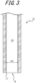
- FIG. 3 is a longitudinal section illustrating an enlargement of a portion including the end 16 of the second tip 15.
- the second tip 15 includes an end opening 17, located at an end 16, and a hollow section 18 connecting to the outside through the end opening 17.
- the end opening 17 of the second tip 15 can collect the sample and/or provide a substance to the sample.
- the second tip 15 can collect the sample through the end opening 17 and hold the collected sample in the hollow section 18 and/or can provide a substance held in the hollow section 18 to the sample through the end opening 17.
- the substance held in the hollow section 18 of the second tip 15 is the same as the substance, contained in the substance container 343, to be provided to the sample.
- the substance held in the hollow section 18 of the second tip 15 may be a substance that was contained in the substance container 343 and collected through the end opening 17 or may be a substance held in advance in the hollow section 18 of the second tip 15.
- the second tip 15 When used to collect the sample, the second tip 15 may, for example, be a nanospray tip for selectively collecting a specific cell or a specific intracellular substance as the sample.
- the inner diameter ⁇ 2 of the end opening 17 when the second tip 15 is a nanospray tip is on the order of 1 micrometer to 10 micrometers.
- the second tip 15 When used to provide a substance to the sample, the second tip 15 is preferably a nanopipette, whose end opening 17 has a smaller inner diameter ⁇ 2 than that of a nanospray tip, so as not to damage the cell serving as the sample when the cell is punctured with the end 16 to inject the substance.
- the inner diameter ⁇ 2 of the end opening 17 when the second tip 15 is a nanopipette is several tens of nanometers or less.
- the first tip 10 is attachable to and detachable from the first operation unit 20 illustrated in FIG. 1 , and the first operation unit 20 is capable of operations on the sample using the first tip 10.
- operations on the sample by the first operation unit 20 include collection of the sample and/or provision of a substance to the sample, as described above.
- the first operation unit 20 may be a suction unit capable of suctioning the sample through the end opening 12.
- the suction unit serving as the first operation unit 20 can, for example, reciprocally move the first tip 10 in the z-direction while the end 11 of the first tip 10 is in contact with the surface of the sample, thereby suctioning the sample through the end opening 12 by capillarity and inertial force.
- the reciprocal motion in the z-direction of the first tip 10 may be performed by the transport unit 310.
- the first operation unit 20 may be an injection unit capable of injecting a substance held in the hollow section 13 while the end 11 of the first tip 10 has punctured a cell serving as the sample.
- the injection unit serving as the first operation unit 20 can apply a voltage, to an electrode provided on the nanopipette, for ejecting the substance held in the hollow section 13, thereby ejecting the substance from the end opening 12.
- the injection unit serving as the first operation unit 20 may be capable of collecting the substance contained in the substance container 343 into the hollow section 13 through the end opening 12 of the first tip 10.
- the first operation unit 20 may include the functions of both of the above-described suction unit and injection unit.
- the second tip 15 is attachable to and detachable from the second operation unit 30, and the second operation unit 30 is capable of operations on the sample using the second tip 15.
- operations on the sample by the second operation unit 30 include collection of the sample and/or provision of a substance to the sample, as described above.
- the second operation unit 30 may be a suction unit capable of suctioning the sample through the end opening 17.
- the suction unit serving as the second operation unit 30 can, for example, reciprocally move the second tip 15 in the z-direction while the end 16 of the second tip 15 is in contact with the surface of the sample, thereby suctioning the sample through the end opening 17 by capillarity and inertial force.
- the reciprocal motion in the z-direction of the second tip 15 may be performed by the transport unit 310.
- the second operation unit 30 may be an injection unit capable of injecting a substance held in the hollow section 18 while the end 16 of the second tip 15 has punctured a cell serving as the sample.
- the injection unit serving as the second operation unit 30 can apply a voltage, to an electrode provided on the nanopipette, for ejecting the substance held in the hollow section 18, thereby ejecting the substance from the end opening 17.
- the injection unit serving as the second operation unit 30 may be capable of collecting the substance contained in the substance container 343 into the hollow section 18 through the end opening 17 of the second tip 15.
- the second operation unit 30 may include the functions of both of the above-described suction unit and injection unit.
- the transport unit 310 supports each of the first operation unit 20 and the second operation unit 30 moveably between the tip region 340 and the sample region 100. Specifically, as illustrated in FIG. 1 , the transport unit 310 supports the first operation unit 20 and the second operation unit 30 moveably in each of the x-direction, the y-direction, and the z-direction.
- the transport unit 310 can highly accurately control the position of the end 11 of the first tip 10 and the position of the end 16 of the second tip 15.
- FIG. 4 schematically illustrates an example configuration of the transport unit 310.
- the transport unit 310 includes a z-direction support 311, a z-direction guide 313, a y-direction support 312, a y-direction guide 315, an x-direction support 314, and an x-direction guide 317.
- the z-direction support 311 supports the first operation unit 20 movably in the z-direction.
- the z-direction guide 313 can guide the z-direction support 311 in the z-direction.
- the y-direction support 312 includes the z-direction guide 313 and supports the z-direction support 311 movably in the y-direction.
- the y-direction guide 315 can guide the y-direction support 312 in the y-direction.
- the x-direction support 314 includes the y-direction guide 315 and supports the y-direction support 312 movably in the x-direction.
- the x-direction guide 317 can guide the x-direction support 314 in the x-direction.
- a fixed body 316 does not move in any of the x-direction, the y-direction, and the z-direction.
- One of the z-direction guide 313 provided in the y-direction support 312 and a non-guiding section guided into the z-direction guide 313 may have the shape of a rail.
- One of the y-direction guide 315 provided in the x-direction support 314 and a non-guiding section guided into the y-direction guide 315 may have the shape of a rail.
- One of the x-direction guide 317 provided in the fixed body 316 and a non-guiding section guided into the x-direction guide 317 may have the shape of a rail.
- the transport unit 310 may include a z-direction support 311a, a z-direction guide 313a, a y-direction support 312a, a y-direction guide 315a, an x-direction support 314a, and an x-direction guide 317a.
- the z-direction support 311 a supports the second operation unit 30 movably in the z-direction.
- the z-direction guide 313a can guide the z-direction support 311a in the z-direction.
- the y-direction support 312a includes the z-direction guide 313a and supports the z-direction support 311a movably in the y-direction.
- the y-direction guide 315a can guide the y-direction support 312a in the y-direction.
- the x-direction support 314a includes the y-direction guide 315a and supports the y-direction support 312a movably in the x-direction.
- the x-direction guide 317a can guide the x-direction support 314a in the x-direction.
- a fixed body 316a does not move in any of the x-direction, the y-direction, and the z-direction.
- One of the z-direction guide 313a provided in the y-direction support 312a and a non-guiding section guided into the z-direction guide 313a may have the shape of a rail.
- One of the y-direction guide 315a provided in the x-direction support 314a and a non-guiding section guided into the y-direction guide 315a may have the shape of a rail.
- One of the x-direction guide 317a provided in the fixed body 316a and a non-guiding section guided into the x-direction guide 317a may have the shape of a rail.
- the fixed body 316 and the x-direction guide 317 for the first operation unit 20 and the fixed body 316a and the x-direction guide 317a for the second operation unit 30 may have a shared configuration.
- the x-direction support 314 for the first operation unit 20 and the x-direction support 314a for the second operation unit 30 interfere with each other in the x-direction.
- the position of the first operation unit 20 is therefore restricted to be on one side in the x-direction (the left side in FIG. 4 ) relative to the position of the second operation unit 30.
- the first operation unit 20 is restricted to be positioned towards the tip region 340 from the second operation unit 30, as illustrated in FIG. 1 .
- the second operation unit 30 is restricted to be positioned towards the sample region 100 from the first operation unit 20.
- the x-direction guide 317 for the first operation unit 20 may also be used as the x-direction guide 317a for the second operation unit 30, and the y-direction guide 315 for the first operation unit 20 may also be used as the y-direction guide 315a for the second operation unit 30.
- the x-direction guide 317 for the first operation unit 20 may also be used as the x-direction guide 317a for the second operation unit 30, the y-direction guide 315 for the first operation unit 20 may also be used as the y-direction guide 315a for the second operation unit, and the z-direction guide 313 for the first operation unit 20 may also be used as the z-direction guide 313a for the second operation unit 30.
- the optical system 200 includes the XY-stage 201 that supports the sample container 110, a microscope 210 that includes an object lens 211, a bright-field illumination source 213, a dichroic mirror 220, a variable magnification lens 221, a bright-field observation camera 222, and a confocal scanner 230.
- the XY-stage 201 supports the sample container 110 moveably in the x-direction and the y-direction. In other words, the XY-stage 201 supports the sample container 110 moveably in the horizontal plane.
- the optical system 200 is described as being capable of confocal two-color fluorescence observation and bright-field observation.
- the optical system 200 is not limited to this configuration.
- the confocal scanner 230 includes a dichroic mirror 231, a pinhole array disc (Nipkow disk) 232, a microlens array disc 233, a relay lens 234, a dichroic mirror 235, a first bandpass filter 236a, a first lens 237a, a first camera 238a for fluorescence observation, a second bandpass filter 236b, a second lens 237b, a second camera 238a for fluorescence observation, and an excitation light source 239.
- a dichroic mirror 231 a pinhole array disc (Nipkow disk) 232, a microlens array disc 233, a relay lens 234, a dichroic mirror 235, a first bandpass filter 236a, a first lens 237a, a first camera 238a for fluorescence observation, a second bandpass filter 236b, a second lens 237b, a second camera 238a for fluorescence observation, and an excitation light source 239.
- the bright-field illumination source 213 irradiates bright-field signal light towards the sample container 110.
- the irradiated bright-field signal light passes through the microscope 210, is reflected by the dichroic mirror 220, and is formed as an image by the variable magnification lens 221 on the bright-field observation camera 222.
- the bright-field illumination source 213 is toric (doughnut-shaped), for example, and partitions a hole 214 passing through in the up-down direction.
- the bright-field illumination source 213 is not limited to being toric and simply needs to have a central portion that is open in top view.
- an excitation light beam having a particular wavelength is emitted from the excitation light source 239 towards the sample container 110.
- a fluorescent signal with a longer wavelength than the excitation light beam is emitted from the sample excited by the excitation light beam.
- the fluorescent signal passes through the pinhole array disc 232 to form a confocal image.
- the fluorescent signal is reflected by the dichroic mirror 231 and forms an image, through the relay lens 234, on the first camera 238a for fluorescence observation and the second camera 238b for fluorescence observation.
- the dichroic mirror 235 has the property of dispersing a fluorescent signal and is used to support simultaneous use of excitation light sources of multiple wavelengths.
- the first bandpass filter 236a and the second bandpass filter 236b are installed to improve the S/N ratio of the images and to transmit only the required wavelength bands of the fluorescent signal. Since the sample emits various fluorescent wavelengths, the first bandpass filter 236a and the second bandpass filter 236b preferably each include a plurality of bandpass filters, for example, and are preferably capable of using a filter wheel or the like to switch to the bandpass filter corresponding to the required wavelength.
- the information processing apparatus 400 is configured by a personal computer (PC) or the like and includes an image acquisition interface 410, an image processor 420, a display 430, an operation reception interface 440, a movement controller 450, and a memory 460.
- PC personal computer
- the image acquisition interface 410 acquires images from the bright-field observation camera 222, the first camera 238a for fluorescence observation, and the second camera 238b for fluorescence observation.
- the image acquisition interface 410 may control the bright-field observation camera 222, the first camera 238a for fluorescence observation, and the second camera 238b for fluorescence observation to be capable of controlling the timing at which images are acquired.
- the image processor 420 is configured by a processor or the like and performs image processing and various analyses on the images acquired by the image acquisition interface 410. Specifically, the image processor 420 can perform template matching or the like on the images acquired from the bright-field observation camera 222, the first camera 238a for fluorescence observation, and the second camera 238b for fluorescence observation to identify the cells/organelles serving as the sample and to calculate features such as the size, luminance, protein amount, ion amount, and the like of the identified cells. The image processor 420 also uses the calculated feature amounts to perform processing such as listing and graphing information related to cells.
- the display 430 is configured to include any suitable display device and performs processing to display the images acquired by the image acquisition interface 410 and the result of image processing and analysis by the image processor 420.
- the operation reception interface 440 is configured to include any appropriate input device, such as a keyboard and mouse, and receives various operations from an operator.
- the movement controller 450 is configured to include a processor or the like and can control movement of the XY-stage 201 to move the sample container 110.
- the movement controller 450 can control movement of the transport unit 310 to move each of the first operation unit 20 and the second operation unit 30 between the tip region 340 and the sample region 100.
- the movement controller 450 can control movement of the first operation unit 20 to attach or remove the first tip 10 and to perform an operation on the sample with the attached first tip 10.
- the movement controller 450 can control movement of the second operation unit 30 to attach or remove the second tip 15 and perform an operation on the sample with the attached second tip 15.
- the movement controller 450 controls movement of the transport unit 310 to move the first operation unit 20 directly above the unused first tip container 341 in the tip region 340 and attach any first tip 10 contained in the unused first tip container 341 to the first operation unit 20. Subsequently, the movement controller 450 controls movement of the transport unit 310 to move the first operation unit 20 directly above the sample container 110 in the sample region 100 and perform an operation on the sample at a predetermined operation position using the first tip 10.
- the operation position can, for example, be along the optical axis of the microscope 210.
- the XY-stage 201 moves the sample container 110 so that the sample targeted for operation is at the operation position.
- the operation position is a position corresponding to the hole 214 of the bright-field illumination source 213, the first tip 10 and the first operation unit 20 can be prevented from interfering with the bright-field illumination source 213 at the time of operations on the sample.
- the movement controller 450 controls movement of the transport unit 310 to move the first tip 10 directly above the used first tip container 342 in the tip region 340 and to detach the first tip 10 from the first operation unit 20 so that the first tip 10 is contained in the used first tip container 342.
- These operations are similar for the second operation unit 30 and the second tip 15 as well.
- the operation on the sample by the first operation unit 20 and the operation on the sample by the second operation unit 30 are performed alternatively.
- the memory 460 stores the images acquired by the image acquisition interface 410, the analysis results of the image processor 420, and the like.
- the memory 460 stores programs and data in advance for the components of the information processing apparatus 400 to execute various functions.
- the memory 460 may store information of a predetermined time, used in the operation example described below, in advance.
- FIG. 5 is a flowchart illustrating a first example of operations of the sample analysis support apparatus 1.
- the first tip 10 and the second tip 15 used in the present example of operations are configured so that the end opening 12 of the first tip 10 and the end opening 17 of the second tip 15 have equivalent sizes.
- the inner diameter ⁇ 1 of the end opening 12 of the first tip 10 and the inner diameter ⁇ 2 of the end opening 17 of the second tip 15 are substantially equal.
- the operation on the sample by the first operation unit 20 includes collection of the sample
- the operation on the sample by the second operation unit 30 includes collection of the sample.
- the first operation unit 20 and the second operation unit 30 are described as being located in the tip region 340 at the start of the present example of operations.
- the movement controller 450 of the sample analysis support apparatus 1 controls movement of the XY-stage 201 to move the sample targeted for operation to the predetermined operation position (step S101).
- the sample analysis support apparatus 1 receives input of setting information, such as imaging conditions of the sample, an imaging range, and output conditions of the sample, by the operator operating the operation reception interface 440.
- setting information such as imaging conditions of the sample, an imaging range, and output conditions of the sample
- an image is captured by at least one of the bright-field observation camera 222, the first camera 238a for fluorescence observation, and the second camera 238b for fluorescence observation.
- the image acquisition interface 410 acquires the image
- the image processor 420 analyzes the image by image processing.
- the display 430 displays the analysis results and receives a designation by the operator, through the operation reception interface 440, of the sample targeted for operation.
- the sample analysis support apparatus 1 may automatically designate the sample targeted for operation based on the analysis results.
- the movement controller 450 then controls movement of the XY-stage 201 to move the sample targeted for operation to the predetermined operation position.
- the movement controller 450 controls movement of the transport unit 310 and the first operation unit 20 to attach the first tip 10 to the first operation unit 20 and controls movement of the transport unit 310 and the second operation unit 30 to attach the second tip 15 to the second operation unit 30 (step S102).
- the processing of step S102 may be executed before the processing of step S101, executed simultaneously with the processing of step S101, or executed after the processing of step S101.
- the movement controller 450 controls movement of the transport unit 310 to move the first operation unit 20 and the second operation unit 30 to the sample region 100 (step S103).
- the movement controller 450 controls movement of the transport unit 310 and the first operation unit 20 to move the first tip 10 to the operation position and collect the sample with the first tip 10 (step S104).
- the sample collected by the first tip 10 may, for example, be a specific cell or an intracellular substance.
- step S104 the movement controller 450 controls movement of the XY-stage 201 to move the next sample targeted for operation to the operation position (step S105). Details on the processing of step S105 are similar to the processing of the above-described step S101.
- the movement controller 450 controls movement of the transport unit 310 and the second operation unit 30 to move the second tip 15 to the operation position and collect the sample with the second tip 15 (step S106).
- the sample collected by the second tip 15 may, for example, be a specific cell or an intracellular substance.
- the movement controller 450 controls movement of the transport unit 310 and the first operation unit 20 to remove the first tip 10 from the operation position.
- the movement controller 450 controls movement of the transport unit 310 to move the first operation unit 20 and the second operation unit 30 to the tip region 340 (step S107).
- the movement controller 450 controls movement of the transport unit 310 and the first operation unit 20 to detach the first tip 10 from the first operation unit 20 and controls movement of the transport unit 310 and the second operation unit 30 to detach the second tip 15 from the second operation unit 30 (step S108).
- the sample analysis support apparatus 1 judges whether operations on the sample are to be continued (step S109). When operations on the sample are to be continued (step S109: Yes), the sample analysis support apparatus 1 returns to the processing of step S101. When operations on the sample are not to be continued (step S109: No), the sample analysis support apparatus 1 ends the present example of operations.
- the judgment of whether to continue operations on the sample may be made based on whether an operation end instruction has been inputted by the operator via the operation reception interface 440, whether a sample targeted for operation can be designated based on the analysis result of the processing of step S101, or the like.
- the processing of steps S107 and S108 may be executed for the first operation unit 20 regardless of whether the processing of steps S105 and S106 has progressed.
- the movement controller 450 may move the first operation unit 20 to the tip region 340 and detach the first tip 10 from the first operation unit 20. This enables the first tip 10 to be stored rapidly in the used first tip container 342 after the sample is collected by first tip 10, thereby suppressing degradation due to vaporization or the like of the sample inside the first tip 10.
- step S104 and the processing of step S106 are executed may be reversed.
- the position of the second operation unit 30 is restricted to be positioned towards the sample region 100 from the first operation unit 20, as illustrated in FIGS. 1 and 4 , then after the sample is collected by the second tip 15 (step S106), it is necessary to wait until the sample is collected by the first tip 10 (step S104) before proceeding to step S107. Therefore, to suppress degradation due to vaporization or the like of the sample inside the first tip 10, the processing of step S104 is preferably executed before the processing of step S106.
- the present example of operations enables the first tip 10 and the second tip, whose end openings are equivalent in size, to collect samples using the corresponding first operation unit 20 and second operation unit 30.
- the transportation time of the collected sample can therefore be shortened and throughput improved as compared to when only one operation unit is included.
- FIG. 6 is a flowchart illustrating a second example of operations of the sample analysis support apparatus 1.
- the first tip 10 and the second tip 15 used in the present example of operations are configured so that the end opening 12 of the first tip 10 is smaller than the end opening 17 of the second tip 15.
- the inner diameter ⁇ 1 of the end opening 12 of the first tip 10 is smaller than the inner diameter ⁇ 2 of the end opening 17 of the second tip 15.
- the operation on the sample by the first operation unit 20 includes collection of the sample
- the operation on the sample by the second operation unit 30 includes collection of the sample.
- the first operation unit 20 and the second operation unit 30 are described as being located in the tip region 340 at the start of the present example of operations.
- the movement controller 450 of the sample analysis support apparatus 1 controls movement of the XY-stage 201 to move the sample targeted for operation to the operation position (step S201). Details on the processing of step S201 are similar to the processing of step S101 of the first example of operations.
- the movement controller 450 controls movement of the transport unit 310 and the first operation unit 20 to attach the first tip 10 to the first operation unit 20 and controls movement of the transport unit 310 and the second operation unit 30 to attach the second tip 15 to the second operation unit 30 (step S202).
- the processing of step S202 may be executed before the processing of step S201, executed simultaneously with the processing of step S201, or executed after the processing of step S201.
- the movement controller 450 controls movement of the transport unit 310 to move the first operation unit 20 and the second operation unit 30 to the sample region 100 (step S203).
- the movement controller 450 controls movement of the transport unit 310 and the first operation unit 20 to move the first tip 10 to the operation position and collect a portion of the sample with the first tip 10 (step S204).
- the portion of the sample collected by the first tip 10 may, for example, be a specific cell or an intracellular substance.
- the movement controller 450 controls movement of the transport unit 310 and the second operation unit 30 to move the second tip 15 to the operation position and collect the sample with the second tip 15 (step S205).
- the sample collected by the second tip 15 may, for example, be a specific cell that includes an intracellular substance collected by the first tip 10.
- the movement controller 450 controls movement of the transport unit 310 and the first operation unit 20 to remove the first tip 10 from the operation position.
- the movement controller 450 controls movement of the transport unit 310 to move the first operation unit 20 and the second operation unit 30 to the tip region 340 (step S206).
- the movement controller 450 controls movement of the transport unit 310 and the first operation unit 20 to detach the first tip 10 from the first operation unit 20 and controls movement of the transport unit 310 and the second operation unit 30 to detach the second tip 15 from the second operation unit 30 (step S207).
- the sample analysis support apparatus 1 judges whether operations on the sample are to be continued (step S208). When operations on the sample are to be continued (step S208: Yes), the sample analysis support apparatus 1 returns to the processing of step S201. When operations on the sample are not to be continued (step S208: No), the sample analysis support apparatus 1 ends the present example of operations.
- the judgment of whether to continue operations on the sample may be made based on whether an operation end instruction has been inputted by the operator via the operation reception interface 440, whether a sample targeted for operation can be designated based on the analysis result of the processing of step S201, or the like.
- the processing of steps S206 and S207 may be executed for the first operation unit 20 regardless of whether the processing of step S205 has progressed.
- the movement controller 450 may move the first operation unit 20 to the tip region 340 and detach the first tip 10 from the first operation unit 20. This enables the first tip 10 to be stored rapidly in the used first tip container 342 after the sample is collected by first tip 10, thereby suppressing degradation due to vaporization or the like of the sample inside the first tip 10.
- the present example of operations enables an intracellular substance of a specific cell to be collected using the first tip 10 with the small end opening 12, and the specific cell to be collected using the second tip 15 with the large end opening 17.
- Mass spectrometry using the intracellular substance from the first tip 10 and RNA analysis using the cell from the second tip 15, for example, can therefore be performed simultaneously on the same cell. Accordingly, the range of analysis applications can be broadened.
- FIG. 7 is a flowchart illustrating a third example of operations of the sample analysis support apparatus 1.
- the operation on the sample by the first operation unit 20 includes provision of a substance to the sample
- the operation on the sample by the second operation unit 30 includes collection of the sample.
- the first operation unit 20 and the second operation unit 30 are described as being located in the tip region 340 at the start of the present example of operations.
- the movement controller 450 of the sample analysis support apparatus 1 controls movement of the XY-stage 201 to move the sample targeted for operation to the operation position (step S301). Details on the processing of step S301 are similar to the processing of step S101 of the first example of operations.
- the movement controller 450 controls movement of the transport unit 310 and the first operation unit 20 to attach the first tip 10 to the first operation unit 20 and controls movement of the transport unit 310 and the second operation unit 30 to attach the second tip 15 to the second operation unit 30 (step S302).
- the processing of step S302 may be executed before the processing of step S301, executed simultaneously with the processing of step S301, or executed after the processing of step S301.
- step S303 the movement controller 450 controls movement of the transport unit 310 and the first operation unit 20 to collect the substance contained in the substance container 343 and store the substance inside the first tip 10 (step S303).
- the processing of step S303 may be omitted.
- the movement controller 450 controls movement of the transport unit 310 to move the first operation unit 20 and the second operation unit 30 to the sample region 100 (step S304).
- the movement controller 450 controls movement of the transport unit 310 and the first operation unit 20 to move the first tip 10 to the operation position and provide the substance inside the first tip 10 to the sample (step S305).
- the sample to which the first tip 10 provides the substance is, for example, a specific cell.
- the movement controller 450 stands by for a predetermined time based on information, stored in the memory 460, indicating the predetermined time (step S306).
- This predetermined time is, for example, the time required until it is possible to observe changes that occur due to the substance, such as a compound, reacting or the like with the sample, such as a cell.
- the movement controller 450 controls movement of the transport unit 310 and the second operation unit 30 to move the second tip 15 to the operation position and collect the sample with the second tip 15 (step S307).
- the sample collected by the second tip 15 is, for example, the specific cell to which the first tip 10 provided the substance, an intracellular substance of the specific cell, or a cell close to the specific cell.
- the movement controller 450 controls movement of the transport unit 310 and the first operation unit 20 to remove the first tip 10 from the operation position.
- the movement controller 450 controls movement of the transport unit 310 to move the first operation unit 20 and the second operation unit 30 to the tip region 340 (step S308).
- the movement controller 450 controls movement of the transport unit 310 and the first operation unit 20 to detach the first tip 10 from the first operation unit 20 and controls movement of the transport unit 310 and the second operation unit 30 to detach the second tip 15 from the second operation unit 30 (step S309).
- the sample analysis support apparatus 1 judges whether operations on the sample are to be continued (step S310). When operations on the sample are to be continued (step S310: Yes), the sample analysis support apparatus 1 returns to the processing of step S301. When operations on the sample are not to be continued (step S310: No), the sample analysis support apparatus 1 ends the present example of operations.
- the judgment of whether to continue operations on the sample may be made based on whether an operation end instruction has been inputted by the operator via the operation reception interface 440, whether a sample targeted for operation can be designated based on the analysis result of the processing of step S3 01, or the like.
- the present example of operations enables a substance such as a compound to be provided to a specific cell using the first tip 10 and enables the specific cell, an intracellular substance of the specific cell, or a cell close to the specific cell to be collected using the second tip 15.
- the effect of providing the substance to the specific cell can therefore be observed.
- the first tip 10 may be used to inject an anticancer agent into a cancer cell, and cells near the cancer cell may be collected using the second tip 15 to observe the effects or the like of the anticancer agent on the nearby cells.
- the sample analysis support apparatus 1 is not limited to including the first operation unit 20 and the second operation unit 30 and may include three or more operation units.
- a plurality of types of substances may be provided to the sample using a plurality of operation units, for example, and the sample may be collected with another operation unit.
- the present disclosure relates to a sample analysis support apparatus.
Landscapes
- Physics & Mathematics (AREA)
- Health & Medical Sciences (AREA)
- Life Sciences & Earth Sciences (AREA)
- Chemical & Material Sciences (AREA)
- Analytical Chemistry (AREA)
- Biochemistry (AREA)
- General Health & Medical Sciences (AREA)
- General Physics & Mathematics (AREA)
- Immunology (AREA)
- Pathology (AREA)
- Apparatus Associated With Microorganisms And Enzymes (AREA)
- Automatic Analysis And Handling Materials Therefor (AREA)
Abstract
Description
- The present application claims priority to and the benefit of Japanese Patent Application No.
2018-110548 filed June 8, 2018 - The present disclosure relates to a sample analysis support apparatus.
- In the field of drug discovery screening, for example, a substance serving as a potential drug, such as a compound, is administered to a sample such as cells, which are the basic constituent element of living organisms. The sample is collected after the sample reacts with the substance. For example, patent literature (PTL) 1 discloses an apparatus that automatically performs operations for collecting the sample at a tip, such as a nanospray tip. PTL 2 discloses a technique for highly accurate positioning control of the tip in the apparatus. PTL 3 discloses a technique for using a nanopipette to administer a substance, such as a compound, to a sample, such as cells.
-
- PTL 1:
JP 6066110 B2 - PTL 2:
JP 6090387 B2 - PTL 3:
WO2013/012452 - The apparatuses disclosed in PTL 1 and 2 include a sample region where a sample is placed, a tip region where a tip is placed, and an operation unit to which the tip is attachable and detachable and which is capable of operations such as collecting the sample with the tip. The apparatus disclosed in PTL 1 and 2 only includes one operation unit, however, and therefore has room for improvement in terms of throughput and range of applications.
- It is therefore an aim of the present disclosure to provide a sample analysis support apparatus capable of improving throughput and/or broadening the range of applications.
- A sample analysis support apparatus according to an embodiment includes a sample region in which a sample is to be disposed; a tip region in which a tip is to be disposed; a first operation unit capable of an operation on the sample using the tip, the tip being attachable to and detachable from the first operation unit; a second operation unit capable of an operation on the sample using the tip, the tip being attachable to and detachable from the second operation unit; a transport unit configured to support each of the first operation unit and the second operation unit moveably between the tip region and the sample region; and a movement controller capable of controlling the transport unit to move each of the first operation unit and the second operation unit between the tip region and the sample region. As compared to when only one operation unit is provided, this configuration can improve throughput and/or broaden the range of applications.
- In an embodiment, the operation on the sample by the first operation unit may include collection of the sample and/or provision of a substance to the sample, and the operation on the sample by the second operation unit may include collection of the sample and/or provision of a substance to the sample.
- In an embodiment, the tip may include an end opening, located at an end of the tip, to enable collection of the sample and/or provision of a substance to the sample. This configuration enables the sample to be collected and/or a substance to be provided to the sample through the end opening precisely.
- In an embodiment, the operation on the sample by the first operation unit may include collection of the sample, and the operation on the sample by the second operation unit may include collection of the sample. This configuration can improve throughput and/or broaden the range of applications.
- In an embodiment, the tip may include a first tip attachable to and detachable from the first operation unit and a second tip attachable to and detachable from the second operation unit, and the end opening of the first tip and the end opening of the second tip may be equivalent in size. As compared to when only one operation unit is provided, this configuration can shorten the transportation time of the collected sample and improve throughput.
- In an embodiment, the tip may include a first tip attachable to and detachable from the first operation unit and a second tip attachable to and detachable from the second operation unit, and the end opening of the first tip may be smaller than the end opening of the second tip. This configuration enables a portion of the specific sample to be collected by the first tip and the entire sample to be collected by the second tip, for example. The range of analysis applications can therefore be broadened.
- In an embodiment, the operation on the sample by the first operation unit may include collection of an intracellular substance of a specific cell, and the operation on the sample by the second operation unit may include collection of the specific cell.
- In an embodiment, the operation on the sample by the first operation unit may include provision of a substance to the sample, and the operation on the sample by the second operation unit may include collection of the sample. This configuration enables collection of the sample to which a substance has been provided, thereby broadening the range of applications.
- In an embodiment, the operation on the sample by the first operation unit may include provision of a substance to a specific cell, and the operation on the sample by the second operation unit may include collection of the specific cell, an intracellular substance of the specific cell, or a cell close to the specific cell. This configuration enables observation of the effect of providing a substance to a specific cell.
- In an embodiment, the sample region may include a predetermined operation position where the operation on the sample by the first operation unit and the operation on the sample by the second operation unit are performed alternatively.
- In an embodiment, the movement controller may be capable of attaching the first tip onto the first operation unit in the tip region, moving the first operation unit from the tip region to the sample region, performing the operation on the sample using the first tip in the sample region, and moving the first operation unit from the sample region to the tip region, and the movement controller may be capable of attaching the second tip onto the second operation unit in the tip region, moving the second operation unit from the tip region to the sample region, performing the operation on the sample using the second tip in the sample region, and moving the second operation unit from the sample region to the tip region. This configuration enables stable operations on the sample.
- In an embodiment, the transport unit may be a transport stage used by both the first operation unit and the second operation unit. This configuration enables a reduction in space and in cost.
- In an embodiment, the transportation stage may include a z-direction support configured to support the first operation unit movably in a z-direction, which is the vertical direction, a z-direction guide capable of guiding the z-direction support in the z-direction, a y-direction support including the z-direction guide and configured to support the z-direction support movably in a y-direction, which is a predetermined direction in the horizontal plane, a y-direction guide capable of guiding the y-direction support in the y-direction, an x-direction support including the y-direction guide and configured to support the y-direction support movably in an x-direction, which is a direction orthogonal to the y-direction in the horizontal plane, and an x-direction guide capable of guiding the x-direction support in the x-direction.
- In an embodiment, the transportation stage may include a z-direction support configured to support the second operation unit movably in a z-direction, which is the vertical direction, a z-direction guide capable of guiding the z-direction support in the z-direction, a y-direction support including the z-direction guide and configured to support the z-direction support movably in a y-direction, which is a predetermined direction in the horizontal plane, a y-direction guide capable of guiding the y-direction support in the y-direction, an x-direction support including the y-direction guide and configured to support the y-direction support movably in an x-direction, which is a direction orthogonal to the y-direction in the horizontal plane, and an x-direction guide capable of guiding the x-direction support in the x-direction.
- In an embodiment, the x-direction guide for the first operation unit may be configured to be also used as the x-direction guide for the second operation unit. This configuration enables a reduction in space and in cost.
- In an embodiment, the x-direction guide for the first operation unit may be configured to be also used as the x-direction guide for the second operation unit, and the y-direction guide for the first operation unit may be configured to be also used as the y-direction guide for the second operation unit. This configuration enables a reduction in space and in cost.
- In an embodiment, the x-direction guide for the first operation unit may be configured to be also used as the x-direction guide for the second operation unit, the y-direction guide for the first operation unit may be configured to be also used as the y-direction guide for the second operation unit, and the z-direction guide for the first operation unit may be configured to be also used as the z-direction guide for the second operation unit. This configuration enables a reduction in space and in cost.
- In an embodiment, the sample region and the tip region may be adjacent to or separated from each other in the x-direction.
- In an embodiment, the sample region and the tip region may be adjacent to or separated from each other in the y-direction.
- The present disclosure can provide a sample analysis support apparatus capable of improving throughput and/or broadening the range of applications.
- In the accompanying drawings:
-
FIG. 1 illustrates the configuration of a sample analysis support apparatus according to an embodiment of the present disclosure; -
FIG. 2 is a longitudinal section illustrating an enlargement of a portion including the end of a first tip ofFIG. 1 ; -
FIG. 3 is a longitudinal section illustrating an enlargement of a portion including the end of a second tip ofFIG. 1 ; -
FIG. 4 schematically illustrates an example configuration of a transport unit ofFIG. 1 ; -
FIG. 5 is a flowchart illustrating a first example of operations of the sample analysis support apparatus ofFIG. 1 ; -
FIG. 6 is a flowchart illustrating a second example of operations of the sample analysis support apparatus ofFIG. 1 ; and -
FIG. 7 is a flowchart illustrating a third example of operations of the sample analysis support apparatus ofFIG. 1 . - Embodiments of the present disclosure are described below using examples, with reference to the drawings. Common elements between drawings are labeled with the same reference numbers. In the present disclosure, the z-direction refers to the vertical direction (the up-down direction in
FIG. 1 and the like), the y-direction refers to a predetermined direction in the horizontal plane (the depth direction inFIG. 1 and the like), and the x-direction refers to a direction orthogonal to the y-direction in the horizontal plane (the left-right direction inFIG. 1 and the like). - First, the configuration of a sample analysis support apparatus 1 according to an embodiment of the present disclosure is described with reference to
FIGS. 1 to 4 .FIG. 1 illustrates the configuration of a sample analysis support apparatus 1 according to an embodiment of the present disclosure. As illustrated inFIG. 1 , the sample analysis support apparatus 1 includes anoperation unit 300, anoptical system 200, and aninformation processing apparatus 400. - As illustrated in
FIG. 1 , theoperation unit 300 includes asample region 100, atip region 340, afirst operation unit 20, asecond operation unit 30, and atransport unit 310. In the present embodiment, thetransport unit 310 is configured as a transport stage used by both thefirst operation unit 20 and thesecond operation unit 30. Thetransport unit 310 may, however, be configured as transport stages provided separately for thefirst operation unit 20 and thesecond operation unit 30. - A sample, such as cells or an intracellular substance, is disposed in the
sample region 100. The sample is housed in asample container 110, such as a cell culture container with a plurality of wells formed therein.FIG. 1 illustrates thesample container 110 as being a microplate cell culture container, but thesample container 110 is not limited to being a microplate and may be a cell culture dish, a cover glass chamber, a petri dish, or the like. Thesample container 110 is supported by an XY-stage 201. Details of the XY-stage 201 are provided below. - Tips are disposed in the
tip region 340. Specifically, an unusedfirst tip container 341 containing unusedfirst tips 10, an unusedsecond tip container 341a containing unusedsecond tips 15, a usedfirst tip container 342 containing usedfirst tips 10, and a usedsecond tip container 342a containing usedsecond tips 15 are disposed in thetip region 340. Here, an unused tip refers to a tip that has not yet been used in an operation on the sample. A used tip refers to a tip that has already been used in an operation on the sample. As illustrated inFIG. 1 , thetip region 340 and thesample region 100 are separated in the x-direction in the present embodiment. Specifically, thetip region 340 is disposed on one side (the left inFIG. 1 ) in the x-direction from thesample region 100. - A
substance container 343 containing a substance to be provided to the sample may further be disposed in thetip region 340. Examples of the substance to be provided to the sample include compounds that are drug candidates, such as anticancer agents. - The
first tip 10 can be attached to and removed from thefirst operation unit 20. Thefirst tip 10 is used in operations on the sample. In the present embodiment, operations on the sample using thefirst tip 10 include collection of the sample and/or provision of a substance to the sample. As illustrated inFIG. 1 , thefirst tip 10 is attached to thefirst operation unit 20 with anend 11 facing down in the present embodiment. -
FIG. 2 is a longitudinal section illustrating an enlargement of a portion including theend 11 of thefirst tip 10. As illustrated inFIG. 2 , thefirst tip 10 includes anend opening 12, located at anend 11, and ahollow section 13 connecting to the outside through theend opening 12. Theend opening 12 of thefirst tip 10 can collect the sample and/or provide a substance to the sample. In other words, thefirst tip 10 can collect the sample through theend opening 12 and hold the collected sample in thehollow section 13 and/or can provide a substance held in thehollow section 13 to the sample through theend opening 12. The substance held in thehollow section 13 of thefirst tip 10 is the same as the substance, contained in thesubstance container 343, to be provided to the sample. The substance held in thehollow section 13 of thefirst tip 10 may be a substance that was contained in thesubstance container 343 and collected through theend opening 12 or may be a substance held in advance in thehollow section 13 of thefirst tip 10. - When used to collect the sample, the
first tip 10 may, for example, be a nanospray tip for selectively collecting a specific cell or a specific intracellular substance as the sample. The inner diameter φ1 of theend opening 12 when thefirst tip 10 is a nanospray tip is on the order of 1 micrometer to 10 micrometers. When used to provide a substance to the sample, thefirst tip 10 is preferably a nanopipette, whose end opening 12 has a smaller inner diameter φ1 than that of a nanospray tip, so as not to damage the cell serving as the sample when the cell is punctured with theend 11 to inject the substance. The inner diameter φ1 of theend opening 12 when thefirst tip 10 is a nanopipette is several tens of nanometers or less. - The
second tip 15 can be attached to and removed from thesecond operation unit 30. Thesecond tip 15 is used in operations on the sample. In the present embodiment, operations on the sample using thesecond tip 15 include collection of the sample and/or provision of a substance to the sample. As illustrated inFIG. 1 , thesecond tip 15 is attached to thesecond operation unit 30 with anend 16 facing down in the present embodiment. -
FIG. 3 is a longitudinal section illustrating an enlargement of a portion including theend 16 of thesecond tip 15. As illustrated inFIG. 3 , thesecond tip 15 includes anend opening 17, located at anend 16, and ahollow section 18 connecting to the outside through theend opening 17. Theend opening 17 of thesecond tip 15 can collect the sample and/or provide a substance to the sample. In other words, thesecond tip 15 can collect the sample through theend opening 17 and hold the collected sample in thehollow section 18 and/or can provide a substance held in thehollow section 18 to the sample through theend opening 17. The substance held in thehollow section 18 of thesecond tip 15 is the same as the substance, contained in thesubstance container 343, to be provided to the sample. The substance held in thehollow section 18 of thesecond tip 15 may be a substance that was contained in thesubstance container 343 and collected through theend opening 17 or may be a substance held in advance in thehollow section 18 of thesecond tip 15. - When used to collect the sample, the
second tip 15 may, for example, be a nanospray tip for selectively collecting a specific cell or a specific intracellular substance as the sample. The inner diameter φ2 of theend opening 17 when thesecond tip 15 is a nanospray tip is on the order of 1 micrometer to 10 micrometers. When used to provide a substance to the sample, thesecond tip 15 is preferably a nanopipette, whose end opening 17 has a smaller inner diameter φ2 than that of a nanospray tip, so as not to damage the cell serving as the sample when the cell is punctured with theend 16 to inject the substance. The inner diameter φ2 of theend opening 17 when thesecond tip 15 is a nanopipette is several tens of nanometers or less. - The
first tip 10 is attachable to and detachable from thefirst operation unit 20 illustrated inFIG. 1 , and thefirst operation unit 20 is capable of operations on the sample using thefirst tip 10. In the present embodiment, operations on the sample by thefirst operation unit 20 include collection of the sample and/or provision of a substance to the sample, as described above. In the case of collecting the sample, thefirst operation unit 20 may be a suction unit capable of suctioning the sample through theend opening 12. The suction unit serving as thefirst operation unit 20 can, for example, reciprocally move thefirst tip 10 in the z-direction while theend 11 of thefirst tip 10 is in contact with the surface of the sample, thereby suctioning the sample through theend opening 12 by capillarity and inertial force. The reciprocal motion in the z-direction of thefirst tip 10 may be performed by thetransport unit 310. In the case of providing a substance to the sample, thefirst operation unit 20 may be an injection unit capable of injecting a substance held in thehollow section 13 while theend 11 of thefirst tip 10 has punctured a cell serving as the sample. When the above-described nanopipette is used as thefirst tip 10, for example, the injection unit serving as thefirst operation unit 20 can apply a voltage, to an electrode provided on the nanopipette, for ejecting the substance held in thehollow section 13, thereby ejecting the substance from theend opening 12. The injection unit serving as thefirst operation unit 20 may be capable of collecting the substance contained in thesubstance container 343 into thehollow section 13 through the end opening 12 of thefirst tip 10. Thefirst operation unit 20 may include the functions of both of the above-described suction unit and injection unit. - The
second tip 15 is attachable to and detachable from thesecond operation unit 30, and thesecond operation unit 30 is capable of operations on the sample using thesecond tip 15. In the present embodiment, operations on the sample by thesecond operation unit 30 include collection of the sample and/or provision of a substance to the sample, as described above. In the case of collecting the sample, thesecond operation unit 30 may be a suction unit capable of suctioning the sample through theend opening 17. The suction unit serving as thesecond operation unit 30 can, for example, reciprocally move thesecond tip 15 in the z-direction while theend 16 of thesecond tip 15 is in contact with the surface of the sample, thereby suctioning the sample through theend opening 17 by capillarity and inertial force. The reciprocal motion in the z-direction of thesecond tip 15 may be performed by thetransport unit 310. In the case of providing a substance to the sample, thesecond operation unit 30 may be an injection unit capable of injecting a substance held in thehollow section 18 while theend 16 of thesecond tip 15 has punctured a cell serving as the sample. When the above-described nanopipette is used as thesecond tip 15, for example, the injection unit serving as thesecond operation unit 30 can apply a voltage, to an electrode provided on the nanopipette, for ejecting the substance held in thehollow section 18, thereby ejecting the substance from theend opening 17. The injection unit serving as thesecond operation unit 30 may be capable of collecting the substance contained in thesubstance container 343 into thehollow section 18 through the end opening 17 of thesecond tip 15. Thesecond operation unit 30 may include the functions of both of the above-described suction unit and injection unit. - The
transport unit 310 supports each of thefirst operation unit 20 and thesecond operation unit 30 moveably between thetip region 340 and thesample region 100. Specifically, as illustrated inFIG. 1 , thetransport unit 310 supports thefirst operation unit 20 and thesecond operation unit 30 moveably in each of the x-direction, the y-direction, and the z-direction. Thetransport unit 310 can highly accurately control the position of theend 11 of thefirst tip 10 and the position of theend 16 of thesecond tip 15. -
FIG. 4 schematically illustrates an example configuration of thetransport unit 310. As illustrated inFIG. 4 , thetransport unit 310 includes a z-direction support 311, a z-direction guide 313, a y-direction support 312, a y-direction guide 315, anx-direction support 314, and an x-direction guide 317. The z-direction support 311 supports thefirst operation unit 20 movably in the z-direction. The z-direction guide 313 can guide the z-direction support 311 in the z-direction. The y-direction support 312 includes the z-direction guide 313 and supports the z-direction support 311 movably in the y-direction. The y-direction guide 315 can guide the y-direction support 312 in the y-direction. Thex-direction support 314 includes the y-direction guide 315 and supports the y-direction support 312 movably in the x-direction. The x-direction guide 317 can guide thex-direction support 314 in the x-direction. Here, a fixed body 316 does not move in any of the x-direction, the y-direction, and the z-direction. One of the z-direction guide 313 provided in the y-direction support 312 and a non-guiding section guided into the z-direction guide 313 may have the shape of a rail. One of the y-direction guide 315 provided in thex-direction support 314 and a non-guiding section guided into the y-direction guide 315 may have the shape of a rail. One of the x-direction guide 317 provided in the fixed body 316 and a non-guiding section guided into the x-direction guide 317 may have the shape of a rail. - As illustrated in
FIG. 4 , thetransport unit 310 may include a z-direction support 311a, a z-direction guide 313a, a y-direction support 312a, a y-direction guide 315a, anx-direction support 314a, and an x-direction guide 317a. The z-direction support 311 a supports thesecond operation unit 30 movably in the z-direction. The z-direction guide 313a can guide the z-direction support 311a in the z-direction. The y-direction support 312a includes the z-direction guide 313a and supports the z-direction support 311a movably in the y-direction. The y-direction guide 315a can guide the y-direction support 312a in the y-direction. Thex-direction support 314a includes the y-direction guide 315a and supports the y-direction support 312a movably in the x-direction. The x-direction guide 317a can guide thex-direction support 314a in the x-direction. Here, a fixed body 316a does not move in any of the x-direction, the y-direction, and the z-direction. One of the z-direction guide 313a provided in the y-direction support 312a and a non-guiding section guided into the z-direction guide 313a may have the shape of a rail. One of the y-direction guide 315a provided in thex-direction support 314a and a non-guiding section guided into the y-direction guide 315a may have the shape of a rail. One of the x-direction guide 317a provided in the fixed body 316a and a non-guiding section guided into the x-direction guide 317a may have the shape of a rail. - As illustrated in
FIG. 4 , the fixed body 316 and the x-direction guide 317 for thefirst operation unit 20 and the fixed body 316a and the x-direction guide 317a for thesecond operation unit 30 may have a shared configuration. In this case, thex-direction support 314 for thefirst operation unit 20 and thex-direction support 314a for thesecond operation unit 30 interfere with each other in the x-direction. The position of thefirst operation unit 20 is therefore restricted to be on one side in the x-direction (the left side inFIG. 4 ) relative to the position of thesecond operation unit 30. Accordingly, thefirst operation unit 20 is restricted to be positioned towards thetip region 340 from thesecond operation unit 30, as illustrated inFIG. 1 . In other words, thesecond operation unit 30 is restricted to be positioned towards thesample region 100 from thefirst operation unit 20. - The x-direction guide 317 for the
first operation unit 20 may also be used as the x-direction guide 317a for thesecond operation unit 30, and the y-direction guide 315 for thefirst operation unit 20 may also be used as the y-direction guide 315a for thesecond operation unit 30. The x-direction guide 317 for thefirst operation unit 20 may also be used as the x-direction guide 317a for thesecond operation unit 30, the y-direction guide 315 for thefirst operation unit 20 may also be used as the y-direction guide 315a for the second operation unit, and the z-direction guide 313 for thefirst operation unit 20 may also be used as the z-direction guide 313a for thesecond operation unit 30. - As illustrated in
FIG. 1 , theoptical system 200 includes the XY-stage 201 that supports thesample container 110, amicroscope 210 that includes anobject lens 211, a bright-field illumination source 213, adichroic mirror 220, avariable magnification lens 221, a bright-field observation camera 222, and aconfocal scanner 230. - The XY-
stage 201 supports thesample container 110 moveably in the x-direction and the y-direction. In other words, the XY-stage 201 supports thesample container 110 moveably in the horizontal plane. - In the present embodiment, the
optical system 200 is described as being capable of confocal two-color fluorescence observation and bright-field observation. Theoptical system 200 is not limited to this configuration. - The
confocal scanner 230 includes adichroic mirror 231, a pinhole array disc (Nipkow disk) 232, amicrolens array disc 233, arelay lens 234, adichroic mirror 235, afirst bandpass filter 236a, afirst lens 237a, afirst camera 238a for fluorescence observation, asecond bandpass filter 236b, asecond lens 237b, asecond camera 238a for fluorescence observation, and anexcitation light source 239. - During bright-field observation, the bright-
field illumination source 213 irradiates bright-field signal light towards thesample container 110. The irradiated bright-field signal light passes through themicroscope 210, is reflected by thedichroic mirror 220, and is formed as an image by thevariable magnification lens 221 on the bright-field observation camera 222. The bright-field illumination source 213 is toric (doughnut-shaped), for example, and partitions ahole 214 passing through in the up-down direction. The bright-field illumination source 213 is not limited to being toric and simply needs to have a central portion that is open in top view. - During fluorescence observation, an excitation light beam having a particular wavelength is emitted from the
excitation light source 239 towards thesample container 110. Subsequently, a fluorescent signal with a longer wavelength than the excitation light beam is emitted from the sample excited by the excitation light beam. The fluorescent signal passes through thepinhole array disc 232 to form a confocal image. Subsequently, the fluorescent signal is reflected by thedichroic mirror 231 and forms an image, through therelay lens 234, on thefirst camera 238a for fluorescence observation and thesecond camera 238b for fluorescence observation. - The
dichroic mirror 235 has the property of dispersing a fluorescent signal and is used to support simultaneous use of excitation light sources of multiple wavelengths. Thefirst bandpass filter 236a and thesecond bandpass filter 236b are installed to improve the S/N ratio of the images and to transmit only the required wavelength bands of the fluorescent signal. Since the sample emits various fluorescent wavelengths, thefirst bandpass filter 236a and thesecond bandpass filter 236b preferably each include a plurality of bandpass filters, for example, and are preferably capable of using a filter wheel or the like to switch to the bandpass filter corresponding to the required wavelength. - As illustrated in
FIG. 1 , theinformation processing apparatus 400 is configured by a personal computer (PC) or the like and includes animage acquisition interface 410, animage processor 420, adisplay 430, anoperation reception interface 440, amovement controller 450, and amemory 460. - The
image acquisition interface 410 acquires images from the bright-field observation camera 222, thefirst camera 238a for fluorescence observation, and thesecond camera 238b for fluorescence observation. Theimage acquisition interface 410 may control the bright-field observation camera 222, thefirst camera 238a for fluorescence observation, and thesecond camera 238b for fluorescence observation to be capable of controlling the timing at which images are acquired. - The
image processor 420 is configured by a processor or the like and performs image processing and various analyses on the images acquired by theimage acquisition interface 410. Specifically, theimage processor 420 can perform template matching or the like on the images acquired from the bright-field observation camera 222, thefirst camera 238a for fluorescence observation, and thesecond camera 238b for fluorescence observation to identify the cells/organelles serving as the sample and to calculate features such as the size, luminance, protein amount, ion amount, and the like of the identified cells. Theimage processor 420 also uses the calculated feature amounts to perform processing such as listing and graphing information related to cells. - The
display 430 is configured to include any suitable display device and performs processing to display the images acquired by theimage acquisition interface 410 and the result of image processing and analysis by theimage processor 420. Theoperation reception interface 440 is configured to include any appropriate input device, such as a keyboard and mouse, and receives various operations from an operator. - The
movement controller 450 is configured to include a processor or the like and can control movement of the XY-stage 201 to move thesample container 110. Themovement controller 450 can control movement of thetransport unit 310 to move each of thefirst operation unit 20 and thesecond operation unit 30 between thetip region 340 and thesample region 100. Themovement controller 450 can control movement of thefirst operation unit 20 to attach or remove thefirst tip 10 and to perform an operation on the sample with the attachedfirst tip 10. Themovement controller 450 can control movement of thesecond operation unit 30 to attach or remove thesecond tip 15 and perform an operation on the sample with the attachedsecond tip 15. - For example, the
movement controller 450 controls movement of thetransport unit 310 to move thefirst operation unit 20 directly above the unusedfirst tip container 341 in thetip region 340 and attach anyfirst tip 10 contained in the unusedfirst tip container 341 to thefirst operation unit 20. Subsequently, themovement controller 450 controls movement of thetransport unit 310 to move thefirst operation unit 20 directly above thesample container 110 in thesample region 100 and perform an operation on the sample at a predetermined operation position using thefirst tip 10. The operation position can, for example, be along the optical axis of themicroscope 210. At this time, the XY-stage 201 moves thesample container 110 so that the sample targeted for operation is at the operation position. In this way, theend 11 of thefirst tip 10 and the sample targeted for operation overlap in the z-direction. When the operation position is a position corresponding to thehole 214 of the bright-field illumination source 213, thefirst tip 10 and thefirst operation unit 20 can be prevented from interfering with the bright-field illumination source 213 at the time of operations on the sample. After the operation is performed on the sample using thefirst tip 10, themovement controller 450 controls movement of thetransport unit 310 to move thefirst tip 10 directly above the usedfirst tip container 342 in thetip region 340 and to detach thefirst tip 10 from thefirst operation unit 20 so that thefirst tip 10 is contained in the usedfirst tip container 342. These operations are similar for thesecond operation unit 30 and thesecond tip 15 as well. At the operation position, the operation on the sample by thefirst operation unit 20 and the operation on the sample by thesecond operation unit 30 are performed alternatively. - The
memory 460 stores the images acquired by theimage acquisition interface 410, the analysis results of theimage processor 420, and the like. Thememory 460 stores programs and data in advance for the components of theinformation processing apparatus 400 to execute various functions. Thememory 460 may store information of a predetermined time, used in the operation example described below, in advance. - Next, examples of operations of the sample analysis support apparatus 1 according to an embodiment of the present disclosure are described with reference to
FIGS. 5 to 7 . The operations of the sample analysis support apparatus 1 are not limited to the examples described below. -
FIG. 5 is a flowchart illustrating a first example of operations of the sample analysis support apparatus 1. Thefirst tip 10 and thesecond tip 15 used in the present example of operations are configured so that the end opening 12 of thefirst tip 10 and the end opening 17 of thesecond tip 15 have equivalent sizes. In other words, the inner diameter φ1 of the end opening 12 of thefirst tip 10 and the inner diameter φ2 of the end opening 17 of thesecond tip 15 are substantially equal. In the present example of operations, the operation on the sample by thefirst operation unit 20 includes collection of the sample, and the operation on the sample by thesecond operation unit 30 includes collection of the sample. Thefirst operation unit 20 and thesecond operation unit 30 are described as being located in thetip region 340 at the start of the present example of operations. - First, the
movement controller 450 of the sample analysis support apparatus 1 controls movement of the XY-stage 201 to move the sample targeted for operation to the predetermined operation position (step S101). In greater detail, the sample analysis support apparatus 1 receives input of setting information, such as imaging conditions of the sample, an imaging range, and output conditions of the sample, by the operator operating theoperation reception interface 440. In accordance with the inputted setting information, an image is captured by at least one of the bright-field observation camera 222, thefirst camera 238a for fluorescence observation, and thesecond camera 238b for fluorescence observation. After image capturing, theimage acquisition interface 410 acquires the image, and theimage processor 420 analyzes the image by image processing. Thedisplay 430 displays the analysis results and receives a designation by the operator, through theoperation reception interface 440, of the sample targeted for operation. Alternatively, the sample analysis support apparatus 1 may automatically designate the sample targeted for operation based on the analysis results. Themovement controller 450 then controls movement of the XY-stage 201 to move the sample targeted for operation to the predetermined operation position. - The
movement controller 450 controls movement of thetransport unit 310 and thefirst operation unit 20 to attach thefirst tip 10 to thefirst operation unit 20 and controls movement of thetransport unit 310 and thesecond operation unit 30 to attach thesecond tip 15 to the second operation unit 30 (step S102). The processing of step S102 may be executed before the processing of step S101, executed simultaneously with the processing of step S101, or executed after the processing of step S101. - After the processing of step S102, the
movement controller 450 controls movement of thetransport unit 310 to move thefirst operation unit 20 and thesecond operation unit 30 to the sample region 100 (step S103). - After the processing of step S103, the
movement controller 450 controls movement of thetransport unit 310 and thefirst operation unit 20 to move thefirst tip 10 to the operation position and collect the sample with the first tip 10 (step S104). The sample collected by thefirst tip 10 may, for example, be a specific cell or an intracellular substance. - After the processing of step S104, the
movement controller 450 controls movement of the XY-stage 201 to move the next sample targeted for operation to the operation position (step S105). Details on the processing of step S105 are similar to the processing of the above-described step S101. - After the processing of step S105, the
movement controller 450 controls movement of thetransport unit 310 and thesecond operation unit 30 to move thesecond tip 15 to the operation position and collect the sample with the second tip 15 (step S106). The sample collected by thesecond tip 15 may, for example, be a specific cell or an intracellular substance. After the processing of step S105 and before the processing of step S106, themovement controller 450 controls movement of thetransport unit 310 and thefirst operation unit 20 to remove thefirst tip 10 from the operation position. - After the processing of step S106, the
movement controller 450 controls movement of thetransport unit 310 to move thefirst operation unit 20 and thesecond operation unit 30 to the tip region 340 (step S107). - After the processing of step S107, the
movement controller 450 controls movement of thetransport unit 310 and thefirst operation unit 20 to detach thefirst tip 10 from thefirst operation unit 20 and controls movement of thetransport unit 310 and thesecond operation unit 30 to detach thesecond tip 15 from the second operation unit 30 (step S108). - The sample analysis support apparatus 1 judges whether operations on the sample are to be continued (step S109). When operations on the sample are to be continued (step S109: Yes), the sample analysis support apparatus 1 returns to the processing of step S101. When operations on the sample are not to be continued (step S109: No), the sample analysis support apparatus 1 ends the present example of operations. The judgment of whether to continue operations on the sample may be made based on whether an operation end instruction has been inputted by the operator via the
operation reception interface 440, whether a sample targeted for operation can be designated based on the analysis result of the processing of step S101, or the like. - After the processing of step S104, the processing of steps S107 and S108 may be executed for the
first operation unit 20 regardless of whether the processing of steps S105 and S106 has progressed. In other words, regardless of whether the processing of steps S105 and S106 has progressed after the sample is collected by thefirst tip 10, themovement controller 450 may move thefirst operation unit 20 to thetip region 340 and detach thefirst tip 10 from thefirst operation unit 20. This enables thefirst tip 10 to be stored rapidly in the usedfirst tip container 342 after the sample is collected byfirst tip 10, thereby suppressing degradation due to vaporization or the like of the sample inside thefirst tip 10. - The order in which the processing of step S104 and the processing of step S106 are executed may be reversed. However, when the position of the
second operation unit 30 is restricted to be positioned towards thesample region 100 from thefirst operation unit 20, as illustrated inFIGS. 1 and4 , then after the sample is collected by the second tip 15 (step S106), it is necessary to wait until the sample is collected by the first tip 10 (step S104) before proceeding to step S107. Therefore, to suppress degradation due to vaporization or the like of the sample inside thefirst tip 10, the processing of step S104 is preferably executed before the processing of step S106. - In this way, the present example of operations enables the
first tip 10 and the second tip, whose end openings are equivalent in size, to collect samples using the correspondingfirst operation unit 20 andsecond operation unit 30. The transportation time of the collected sample can therefore be shortened and throughput improved as compared to when only one operation unit is included. -
FIG. 6 is a flowchart illustrating a second example of operations of the sample analysis support apparatus 1. Thefirst tip 10 and thesecond tip 15 used in the present example of operations are configured so that the end opening 12 of thefirst tip 10 is smaller than the end opening 17 of thesecond tip 15. In other words, the inner diameter φ1 of the end opening 12 of thefirst tip 10 is smaller than the inner diameter φ2 of the end opening 17 of thesecond tip 15. In the present example of operations, the operation on the sample by thefirst operation unit 20 includes collection of the sample, and the operation on the sample by thesecond operation unit 30 includes collection of the sample. Thefirst operation unit 20 and thesecond operation unit 30 are described as being located in thetip region 340 at the start of the present example of operations. - First, the
movement controller 450 of the sample analysis support apparatus 1 controls movement of the XY-stage 201 to move the sample targeted for operation to the operation position (step S201). Details on the processing of step S201 are similar to the processing of step S101 of the first example of operations. - The
movement controller 450 controls movement of thetransport unit 310 and thefirst operation unit 20 to attach thefirst tip 10 to thefirst operation unit 20 and controls movement of thetransport unit 310 and thesecond operation unit 30 to attach thesecond tip 15 to the second operation unit 30 (step S202). The processing of step S202 may be executed before the processing of step S201, executed simultaneously with the processing of step S201, or executed after the processing of step S201. - After the processing of step S202, the
movement controller 450 controls movement of thetransport unit 310 to move thefirst operation unit 20 and thesecond operation unit 30 to the sample region 100 (step S203). - After the processing of step S203, the
movement controller 450 controls movement of thetransport unit 310 and thefirst operation unit 20 to move thefirst tip 10 to the operation position and collect a portion of the sample with the first tip 10 (step S204). The portion of the sample collected by thefirst tip 10 may, for example, be a specific cell or an intracellular substance. - After the processing of step S204, the
movement controller 450 controls movement of thetransport unit 310 and thesecond operation unit 30 to move thesecond tip 15 to the operation position and collect the sample with the second tip 15 (step S205). The sample collected by thesecond tip 15 may, for example, be a specific cell that includes an intracellular substance collected by thefirst tip 10. After the processing of step S204 and before the processing of step S205, themovement controller 450 controls movement of thetransport unit 310 and thefirst operation unit 20 to remove thefirst tip 10 from the operation position. - After the processing of step S205, the
movement controller 450 controls movement of thetransport unit 310 to move thefirst operation unit 20 and thesecond operation unit 30 to the tip region 340 (step S206). - After the processing of step S206, the
movement controller 450 controls movement of thetransport unit 310 and thefirst operation unit 20 to detach thefirst tip 10 from thefirst operation unit 20 and controls movement of thetransport unit 310 and thesecond operation unit 30 to detach thesecond tip 15 from the second operation unit 30 (step S207). - The sample analysis support apparatus 1 judges whether operations on the sample are to be continued (step S208). When operations on the sample are to be continued (step S208: Yes), the sample analysis support apparatus 1 returns to the processing of step S201. When operations on the sample are not to be continued (step S208: No), the sample analysis support apparatus 1 ends the present example of operations. The judgment of whether to continue operations on the sample may be made based on whether an operation end instruction has been inputted by the operator via the
operation reception interface 440, whether a sample targeted for operation can be designated based on the analysis result of the processing of step S201, or the like. - After the processing of step S204, the processing of steps S206 and S207 may be executed for the
first operation unit 20 regardless of whether the processing of step S205 has progressed. In other words, regardless of whether the processing of step S205 has progressed after the sample is collected by thefirst tip 10, themovement controller 450 may move thefirst operation unit 20 to thetip region 340 and detach thefirst tip 10 from thefirst operation unit 20. This enables thefirst tip 10 to be stored rapidly in the usedfirst tip container 342 after the sample is collected byfirst tip 10, thereby suppressing degradation due to vaporization or the like of the sample inside thefirst tip 10. - In this way, the present example of operations enables an intracellular substance of a specific cell to be collected using the
first tip 10 with thesmall end opening 12, and the specific cell to be collected using thesecond tip 15 with thelarge end opening 17. Mass spectrometry using the intracellular substance from thefirst tip 10 and RNA analysis using the cell from thesecond tip 15, for example, can therefore be performed simultaneously on the same cell. Accordingly, the range of analysis applications can be broadened. -
FIG. 7 is a flowchart illustrating a third example of operations of the sample analysis support apparatus 1. In the present example of operations, the operation on the sample by thefirst operation unit 20 includes provision of a substance to the sample, and the operation on the sample by thesecond operation unit 30 includes collection of the sample. Thefirst operation unit 20 and thesecond operation unit 30 are described as being located in thetip region 340 at the start of the present example of operations. - First, the
movement controller 450 of the sample analysis support apparatus 1 controls movement of the XY-stage 201 to move the sample targeted for operation to the operation position (step S301). Details on the processing of step S301 are similar to the processing of step S101 of the first example of operations. - The
movement controller 450 controls movement of thetransport unit 310 and thefirst operation unit 20 to attach thefirst tip 10 to thefirst operation unit 20 and controls movement of thetransport unit 310 and thesecond operation unit 30 to attach thesecond tip 15 to the second operation unit 30 (step S302). The processing of step S302 may be executed before the processing of step S301, executed simultaneously with the processing of step S301, or executed after the processing of step S301. - After the processing of step S303, the
movement controller 450 controls movement of thetransport unit 310 and thefirst operation unit 20 to collect the substance contained in thesubstance container 343 and store the substance inside the first tip 10 (step S303). When thefirst tip 10 holds the substance in advance, the processing of step S303 may be omitted. - After the processing of step S303, the
movement controller 450 controls movement of thetransport unit 310 to move thefirst operation unit 20 and thesecond operation unit 30 to the sample region 100 (step S304). - After the processing of step S304, the
movement controller 450 controls movement of thetransport unit 310 and thefirst operation unit 20 to move thefirst tip 10 to the operation position and provide the substance inside thefirst tip 10 to the sample (step S305). The sample to which thefirst tip 10 provides the substance is, for example, a specific cell. - After the processing of step S305, the
movement controller 450 stands by for a predetermined time based on information, stored in thememory 460, indicating the predetermined time (step S306). This predetermined time is, for example, the time required until it is possible to observe changes that occur due to the substance, such as a compound, reacting or the like with the sample, such as a cell. - After the processing of step S306, the
movement controller 450 controls movement of thetransport unit 310 and thesecond operation unit 30 to move thesecond tip 15 to the operation position and collect the sample with the second tip 15 (step S307). The sample collected by thesecond tip 15 is, for example, the specific cell to which thefirst tip 10 provided the substance, an intracellular substance of the specific cell, or a cell close to the specific cell. After the processing of step S305 and before the processing of step S307, themovement controller 450 controls movement of thetransport unit 310 and thefirst operation unit 20 to remove thefirst tip 10 from the operation position. - After the processing of step S307, the
movement controller 450 controls movement of thetransport unit 310 to move thefirst operation unit 20 and thesecond operation unit 30 to the tip region 340 (step S308). - After the processing of step S308, the
movement controller 450 controls movement of thetransport unit 310 and thefirst operation unit 20 to detach thefirst tip 10 from thefirst operation unit 20 and controls movement of thetransport unit 310 and thesecond operation unit 30 to detach thesecond tip 15 from the second operation unit 30 (step S309). - The sample analysis support apparatus 1 judges whether operations on the sample are to be continued (step S310). When operations on the sample are to be continued (step S310: Yes), the sample analysis support apparatus 1 returns to the processing of step S301. When operations on the sample are not to be continued (step S310: No), the sample analysis support apparatus 1 ends the present example of operations. The judgment of whether to continue operations on the sample may be made based on whether an operation end instruction has been inputted by the operator via the
operation reception interface 440, whether a sample targeted for operation can be designated based on the analysis result of the processing of step S3 01, or the like. - In this way, the present example of operations enables a substance such as a compound to be provided to a specific cell using the
first tip 10 and enables the specific cell, an intracellular substance of the specific cell, or a cell close to the specific cell to be collected using thesecond tip 15. The effect of providing the substance to the specific cell can therefore be observed. Specifically, thefirst tip 10 may be used to inject an anticancer agent into a cancer cell, and cells near the cancer cell may be collected using thesecond tip 15 to observe the effects or the like of the anticancer agent on the nearby cells. - The present disclosure is not limited to the configurations specified in the above embodiment, and a variety of modifications may be made without departing from the scope of the claims. For example, the sample analysis support apparatus 1 is not limited to including the
first operation unit 20 and thesecond operation unit 30 and may include three or more operation units. In this case, a plurality of types of substances may be provided to the sample using a plurality of operation units, for example, and the sample may be collected with another operation unit. - The present disclosure relates to a sample analysis support apparatus.
-
- 1
- Sample analysis support apparatus
- 10
- First tip
- 11
- End of first tip
- 12
- End opening of first tip
- 13
- Hollow section of first tip
- 15
- Second tip
- 16
- End of second tip
- 17
- End opening of second tip
- 18
- Hollow section of second tip
- 20
- First operation unit
- 30
- Second operation unit
- 100
- Sample region
- 110
- Sample container
- 200
- Optical system
- 201
- XY-stage
- 210
- Microscope
- 211
- Object lens
- 213
- Bright-field illumination source
- 214
- Hole
- 220
- Dichroic mirror
- 221
- Variable magnification lens
- 222
- Bright-field observation camera
- 230
- Confocal scanner
- 231
- Dichroic mirror
- 232
- Pinhole array disc
- 233
- Microlens array disc
- 234
- Relay lens
- 235
- Dichroic mirror
- 236a
- First bandpass filter
- 236b
- Second bandpass filter
- 237a
- First lens
- 237b
- Second lens
- 238a
- First camera for fluorescence observation
- 238b
- Second camera for fluorescence observation
- 239
- Excitation light source
- 300
- Operation unit
- 310
- Transport unit
- 311, 311a
- Z-direction support
- 312, 312a
- Y-direction support
- 313, 313a
- Z-direction guide
- 314, 314a
- X-direction support
- 315, 315a
- Y-direction guide
- 316, 316a
- Fixed body
- 317, 317a
- X-direction guide
- 340
- Tip region
- 341
- Unused first tip container
- 341a
- Unused second tip container
- 342
- Used first tip container
- 342a
- Used second tip container
- 343
- Substance container
- 400
- Information processing apparatus
- 410
- Image acquisition interface
- 420
- Image processor
- 430
- Display
- 440
- Operation reception interface
- 450
- Movement controller
- 460
- Memory
- φ1
- Inner diameter of end opening of first tip
- φ2
- Inner diameter of end opening of second tip
Claims (10)
- A sample analysis support apparatus comprising:a sample region in which a sample is to be disposed;a tip region in which a tip is to be disposed;a first operation unit capable of an operation on the sample using the tip, the tip being attachable to and detachable from the first operation unit;a second operation unit capable of an operation on the sample using the tip, the tip being attachable to and detachable from the second operation unit;a transport unit configured to support each of the first operation unit and the second operation unit moveably between the tip region and the sample region; anda movement controller capable of controlling the transport unit to move each of the first operation unit and the second operation unit between the tip region and the sample region.
- The sample analysis support apparatus of claim 1,
wherein the operation on the sample by the first operation unit comprises collection of the sample and/or provision of a substance to the sample; and
wherein the operation on the sample by the second operation unit comprises collection of the sample and/or provision of a substance to the sample. - The sample analysis support apparatus of claim 2, wherein the tip comprises an end opening, located at an end of the tip, to enable collection of the sample and/or provision of a substance to the sample.
- The sample analysis support apparatus of claim 3,
wherein the operation on the sample by the first operation unit comprises collection of the sample; and
wherein the operation on the sample by the second operation unit comprises collection of the sample. - The sample analysis support apparatus of claim 4,
wherein the tip comprises a first tip attachable to and detachable from the first operation unit and a second tip attachable to and detachable from the second operation unit; and
wherein the end opening of the first tip and the end opening of the second tip are equivalent in size. - The sample analysis support apparatus of claim 4,
wherein the tip comprises a first tip attachable to and detachable from the first operation unit and a second tip attachable to and detachable from the second operation unit; and
wherein the end opening of the first tip is smaller than the end opening of the second tip. - The sample analysis support apparatus of claim 6,
wherein the operation on the sample by the first operation unit comprises collection of an intracellular substance of a specific cell; and
wherein the operation on the sample by the second operation unit comprises collection of the specific cell. - The sample analysis support apparatus of claim 3,
wherein the operation on the sample by the first operation unit comprises provision of a substance to the sample; and
wherein the operation on the sample by the second operation unit comprises collection of the sample. - The sample analysis support apparatus of claim 8,
wherein the operation on the sample by the first operation unit comprises provision of a substance to a specific cell; and
wherein the operation on the sample by the second operation unit comprises collection of the specific cell, an intracellular substance of the specific cell, or a cell close to the specific cell. - The sample analysis support apparatus of any one of claims 1 to 9, wherein the sample region comprises a predetermined operation position where the operation on the sample by the first operation unit and the operation on the sample by the second operation unit are performed alternatively.
Applications Claiming Priority (2)
| Application Number | Priority Date | Filing Date | Title |
|---|---|---|---|
| JP2018110548A JP7155630B2 (en) | 2018-06-08 | 2018-06-08 | Sample analysis support device |
| PCT/JP2019/017075 WO2019235089A1 (en) | 2018-06-08 | 2019-04-22 | Sample analysis assisting apparatus |
Publications (3)
| Publication Number | Publication Date |
|---|---|
| EP3805359A1 true EP3805359A1 (en) | 2021-04-14 |
| EP3805359A4 EP3805359A4 (en) | 2022-03-23 |
| EP3805359B1 EP3805359B1 (en) | 2023-07-26 |
Family
ID=68769480
Family Applications (1)
| Application Number | Title | Priority Date | Filing Date |
|---|---|---|---|
| EP19814438.8A Active EP3805359B1 (en) | 2018-06-08 | 2019-04-22 | Sample analysis support apparatus |
Country Status (4)
| Country | Link |
|---|---|
| US (1) | US11852646B2 (en) |
| EP (1) | EP3805359B1 (en) |
| JP (1) | JP7155630B2 (en) |
| WO (1) | WO2019235089A1 (en) |
Cited By (1)
| Publication number | Priority date | Publication date | Assignee | Title |
|---|---|---|---|---|
| EP4696767A1 (en) * | 2024-08-16 | 2026-02-18 | Yokogawa Electric Corporation | Cell suction system |
Family Cites Families (15)
| Publication number | Priority date | Publication date | Assignee | Title |
|---|---|---|---|---|
| EP0628823A4 (en) * | 1992-11-20 | 1996-05-08 | Dainabot Co Ltd | MULTI-CHANNEL AUTOMATIC IMMUNOASSAY SYSTEM. |
| JP3425902B2 (en) * | 1999-08-31 | 2003-07-14 | 株式会社日立製作所 | Sample pretreatment device |
| JP2002262856A (en) * | 2001-03-07 | 2002-09-17 | Japan Tissue Engineering:Kk | Automatic medium exchange method, program and automatic medium exchange apparatus |
| JP4016811B2 (en) * | 2002-11-15 | 2007-12-05 | 日立工機株式会社 | Automatic dispensing device |
| JP4213014B2 (en) | 2003-10-23 | 2009-01-21 | アロカ株式会社 | Dispensing device |
| JP2005341877A (en) * | 2004-06-03 | 2005-12-15 | Olympus Corp | Culture treatment apparatus, automatic culture apparatus, contact detection method and liquid droplet detection method |
| JP2006158335A (en) * | 2004-12-09 | 2006-06-22 | Olympus Corp | Dividedly injecting device and culture treatment apparatus |
| JP2011120582A (en) * | 2009-11-16 | 2011-06-23 | Humanix:Kk | Automated apparatus for component capture, injection, and molecular analysis accompanied by observation of microregion such as cell |
| EP2681304B1 (en) | 2011-03-03 | 2020-05-27 | The Regents of The University of California | Method of patterning cells on a substrate |
| US9103809B2 (en) * | 2012-04-23 | 2015-08-11 | Agilent Technologies, Inc. | Liquid handler with dual pipetting groups |
| JP6066110B2 (en) | 2014-06-11 | 2017-01-25 | 横河電機株式会社 | Cell suction support system |
| EP3034602B1 (en) * | 2014-12-15 | 2020-02-12 | Yokogawa Electric Corporation | Cell suction system, and method for performing suction work of intracellular substance using the same |
| JP6090387B2 (en) | 2014-12-15 | 2017-03-08 | 横河電機株式会社 | Cell suction system and method for sucking intracellular substance using the same |
| JP6856240B2 (en) | 2017-01-11 | 2021-04-07 | 公立大学法人名古屋市立大学 | Method for preparing vascular endothelial progenitor cells |
| WO2019010515A1 (en) * | 2017-07-14 | 2019-01-17 | Meon Medical Solutions Gmbh & Co Kg | AUTOMATIC PIPETTING DEVICE FOR THE SAMPLING AND / OR REAGENT TRANSFER AND METHOD FOR TRANSFERRING LIQUID SAMPLES AND / OR REAGENTS |
-
2018
- 2018-06-08 JP JP2018110548A patent/JP7155630B2/en active Active
-
2019
- 2019-04-22 WO PCT/JP2019/017075 patent/WO2019235089A1/en not_active Ceased
- 2019-04-22 US US17/050,681 patent/US11852646B2/en active Active
- 2019-04-22 EP EP19814438.8A patent/EP3805359B1/en active Active
Cited By (1)
| Publication number | Priority date | Publication date | Assignee | Title |
|---|---|---|---|---|
| EP4696767A1 (en) * | 2024-08-16 | 2026-02-18 | Yokogawa Electric Corporation | Cell suction system |
Also Published As
| Publication number | Publication date |
|---|---|
| EP3805359B1 (en) | 2023-07-26 |
| JP2019208479A (en) | 2019-12-12 |
| JP7155630B2 (en) | 2022-10-19 |
| US11852646B2 (en) | 2023-12-26 |
| EP3805359A4 (en) | 2022-03-23 |
| WO2019235089A1 (en) | 2019-12-12 |
| US20210231697A1 (en) | 2021-07-29 |
Similar Documents
| Publication | Publication Date | Title |
|---|---|---|
| JP6066110B2 (en) | Cell suction support system | |
| US10746981B2 (en) | Methods and devices for imaging large intact tissue samples | |
| CN101776793B (en) | Biological sample image acquiring apparatus, and biological sample image acquiring method | |
| EP2941663B1 (en) | A method for automated platform and/or reference object independent acquisition of positional information and localization of objects of interest in a microscope | |
| US20130015370A1 (en) | Confocal fluorescence slide scanner with parallel detection | |
| EP3441456B1 (en) | Cell aspiration support system | |
| CN106461558A (en) | Optical analysis device | |
| US9310596B2 (en) | Compound microscope device | |
| CN110799880A (en) | Adjustable slide holder for slides of different sizes | |
| EP2037255A1 (en) | Spectrum observation method and spectrum observation system | |
| JP2024138365A (en) | Methods, apparatus, systems and devices for mobile digital spatial profiling of pathology tissue specimens. | |
| EP3805359B1 (en) | Sample analysis support apparatus | |
| JP2021184769A (en) | Cell suction support device and control method of cell suction support device | |
| US20220054011A1 (en) | Multi-modal imaging systems and methods | |
| US20210181076A1 (en) | Method and apparatus for collecting biomolecules from specific region of tissue section | |
| US20190011478A1 (en) | Observation method using compound microscope including an inverted optical microscope and atomic force microscope, program to perform observation method, and compound microscope | |
| EP3922973B1 (en) | Analysis apparatus | |
| Park et al. | Conducting multiple imaging modes with one fluorescence microscope | |
| CN106338546A (en) | High-spatial-resolution imaging mass spectrometry device | |
| JP7031294B2 (en) | Drug discovery screening device | |
| WO2023161375A1 (en) | Device for measuring intrinsic autofluorescence of a biological sample and method using thereof | |
| JP7006360B2 (en) | Sampling device and sampling method | |
| CN107290278B (en) | Split scanning type optical microscope device | |
| EP4283372B1 (en) | Digital pathology apparatus housing with rail system, speakerless audio system, and electromagnetic radiation shielding | |
| Spille | Three-dimensional single particle tracking in a light sheet microscope |
Legal Events
| Date | Code | Title | Description |
|---|---|---|---|
| STAA | Information on the status of an ep patent application or granted ep patent |
Free format text: STATUS: THE INTERNATIONAL PUBLICATION HAS BEEN MADE |
|
| PUAI | Public reference made under article 153(3) epc to a published international application that has entered the european phase |
Free format text: ORIGINAL CODE: 0009012 |
|
| STAA | Information on the status of an ep patent application or granted ep patent |
Free format text: STATUS: REQUEST FOR EXAMINATION WAS MADE |
|
| 17P | Request for examination filed |
Effective date: 20201124 |
|
| AK | Designated contracting states |
Kind code of ref document: A1 Designated state(s): AL AT BE BG CH CY CZ DE DK EE ES FI FR GB GR HR HU IE IS IT LI LT LU LV MC MK MT NL NO PL PT RO RS SE SI SK SM TR |
|
| AX | Request for extension of the european patent |
Extension state: BA ME |
|
| DAV | Request for validation of the european patent (deleted) | ||
| DAX | Request for extension of the european patent (deleted) | ||
| A4 | Supplementary search report drawn up and despatched |
Effective date: 20220218 |
|
| RIC1 | Information provided on ipc code assigned before grant |
Ipc: G01N 35/10 20060101ALI20220215BHEP Ipc: C12M 1/26 20060101AFI20220215BHEP |
|
| STAA | Information on the status of an ep patent application or granted ep patent |
Free format text: STATUS: EXAMINATION IS IN PROGRESS |
|
| 17Q | First examination report despatched |
Effective date: 20221027 |
|
| GRAP | Despatch of communication of intention to grant a patent |
Free format text: ORIGINAL CODE: EPIDOSNIGR1 |
|
| STAA | Information on the status of an ep patent application or granted ep patent |
Free format text: STATUS: GRANT OF PATENT IS INTENDED |
|
| INTG | Intention to grant announced |
Effective date: 20230224 |
|
| GRAS | Grant fee paid |
Free format text: ORIGINAL CODE: EPIDOSNIGR3 |
|
| GRAA | (expected) grant |
Free format text: ORIGINAL CODE: 0009210 |
|
| STAA | Information on the status of an ep patent application or granted ep patent |
Free format text: STATUS: THE PATENT HAS BEEN GRANTED |
|
| P01 | Opt-out of the competence of the unified patent court (upc) registered |
Effective date: 20230603 |
|
| AK | Designated contracting states |
Kind code of ref document: B1 Designated state(s): AL AT BE BG CH CY CZ DE DK EE ES FI FR GB GR HR HU IE IS IT LI LT LU LV MC MK MT NL NO PL PT RO RS SE SI SK SM TR |
|
| REG | Reference to a national code |
Ref country code: CH Ref legal event code: EP |
|
| REG | Reference to a national code |
Ref country code: IE Ref legal event code: FG4D |
|
| REG | Reference to a national code |
Ref country code: DE Ref legal event code: R096 Ref document number: 602019033693 Country of ref document: DE |
|
| REG | Reference to a national code |
Ref country code: LT Ref legal event code: MG9D |
|
| REG | Reference to a national code |
Ref country code: NL Ref legal event code: MP Effective date: 20230726 |
|
| REG | Reference to a national code |
Ref country code: AT Ref legal event code: MK05 Ref document number: 1591949 Country of ref document: AT Kind code of ref document: T Effective date: 20230726 |
|
| PG25 | Lapsed in a contracting state [announced via postgrant information from national office to epo] |
Ref country code: NL Free format text: LAPSE BECAUSE OF FAILURE TO SUBMIT A TRANSLATION OF THE DESCRIPTION OR TO PAY THE FEE WITHIN THE PRESCRIBED TIME-LIMIT Effective date: 20230726 |
|
| PG25 | Lapsed in a contracting state [announced via postgrant information from national office to epo] |
Ref country code: GR Free format text: LAPSE BECAUSE OF FAILURE TO SUBMIT A TRANSLATION OF THE DESCRIPTION OR TO PAY THE FEE WITHIN THE PRESCRIBED TIME-LIMIT Effective date: 20231027 |
|
| PG25 | Lapsed in a contracting state [announced via postgrant information from national office to epo] |
Ref country code: IS Free format text: LAPSE BECAUSE OF FAILURE TO SUBMIT A TRANSLATION OF THE DESCRIPTION OR TO PAY THE FEE WITHIN THE PRESCRIBED TIME-LIMIT Effective date: 20231126 |
|
| PG25 | Lapsed in a contracting state [announced via postgrant information from national office to epo] |
Ref country code: SE Free format text: LAPSE BECAUSE OF FAILURE TO SUBMIT A TRANSLATION OF THE DESCRIPTION OR TO PAY THE FEE WITHIN THE PRESCRIBED TIME-LIMIT Effective date: 20230726 Ref country code: RS Free format text: LAPSE BECAUSE OF FAILURE TO SUBMIT A TRANSLATION OF THE DESCRIPTION OR TO PAY THE FEE WITHIN THE PRESCRIBED TIME-LIMIT Effective date: 20230726 Ref country code: PT Free format text: LAPSE BECAUSE OF FAILURE TO SUBMIT A TRANSLATION OF THE DESCRIPTION OR TO PAY THE FEE WITHIN THE PRESCRIBED TIME-LIMIT Effective date: 20231127 Ref country code: NO Free format text: LAPSE BECAUSE OF FAILURE TO SUBMIT A TRANSLATION OF THE DESCRIPTION OR TO PAY THE FEE WITHIN THE PRESCRIBED TIME-LIMIT Effective date: 20231026 Ref country code: LV Free format text: LAPSE BECAUSE OF FAILURE TO SUBMIT A TRANSLATION OF THE DESCRIPTION OR TO PAY THE FEE WITHIN THE PRESCRIBED TIME-LIMIT Effective date: 20230726 Ref country code: LT Free format text: LAPSE BECAUSE OF FAILURE TO SUBMIT A TRANSLATION OF THE DESCRIPTION OR TO PAY THE FEE WITHIN THE PRESCRIBED TIME-LIMIT Effective date: 20230726 Ref country code: IS Free format text: LAPSE BECAUSE OF FAILURE TO SUBMIT A TRANSLATION OF THE DESCRIPTION OR TO PAY THE FEE WITHIN THE PRESCRIBED TIME-LIMIT Effective date: 20231126 Ref country code: HR Free format text: LAPSE BECAUSE OF FAILURE TO SUBMIT A TRANSLATION OF THE DESCRIPTION OR TO PAY THE FEE WITHIN THE PRESCRIBED TIME-LIMIT Effective date: 20230726 Ref country code: GR Free format text: LAPSE BECAUSE OF FAILURE TO SUBMIT A TRANSLATION OF THE DESCRIPTION OR TO PAY THE FEE WITHIN THE PRESCRIBED TIME-LIMIT Effective date: 20231027 Ref country code: FI Free format text: LAPSE BECAUSE OF FAILURE TO SUBMIT A TRANSLATION OF THE DESCRIPTION OR TO PAY THE FEE WITHIN THE PRESCRIBED TIME-LIMIT Effective date: 20230726 Ref country code: AT Free format text: LAPSE BECAUSE OF FAILURE TO SUBMIT A TRANSLATION OF THE DESCRIPTION OR TO PAY THE FEE WITHIN THE PRESCRIBED TIME-LIMIT Effective date: 20230726 |
|
| PG25 | Lapsed in a contracting state [announced via postgrant information from national office to epo] |
Ref country code: PL Free format text: LAPSE BECAUSE OF FAILURE TO SUBMIT A TRANSLATION OF THE DESCRIPTION OR TO PAY THE FEE WITHIN THE PRESCRIBED TIME-LIMIT Effective date: 20230726 |
|
| PG25 | Lapsed in a contracting state [announced via postgrant information from national office to epo] |
Ref country code: ES Free format text: LAPSE BECAUSE OF FAILURE TO SUBMIT A TRANSLATION OF THE DESCRIPTION OR TO PAY THE FEE WITHIN THE PRESCRIBED TIME-LIMIT Effective date: 20230726 |
|
| REG | Reference to a national code |
Ref country code: DE Ref legal event code: R097 Ref document number: 602019033693 Country of ref document: DE |
|
| PG25 | Lapsed in a contracting state [announced via postgrant information from national office to epo] |
Ref country code: SM Free format text: LAPSE BECAUSE OF FAILURE TO SUBMIT A TRANSLATION OF THE DESCRIPTION OR TO PAY THE FEE WITHIN THE PRESCRIBED TIME-LIMIT Effective date: 20230726 Ref country code: RO Free format text: LAPSE BECAUSE OF FAILURE TO SUBMIT A TRANSLATION OF THE DESCRIPTION OR TO PAY THE FEE WITHIN THE PRESCRIBED TIME-LIMIT Effective date: 20230726 Ref country code: ES Free format text: LAPSE BECAUSE OF FAILURE TO SUBMIT A TRANSLATION OF THE DESCRIPTION OR TO PAY THE FEE WITHIN THE PRESCRIBED TIME-LIMIT Effective date: 20230726 Ref country code: EE Free format text: LAPSE BECAUSE OF FAILURE TO SUBMIT A TRANSLATION OF THE DESCRIPTION OR TO PAY THE FEE WITHIN THE PRESCRIBED TIME-LIMIT Effective date: 20230726 Ref country code: DK Free format text: LAPSE BECAUSE OF FAILURE TO SUBMIT A TRANSLATION OF THE DESCRIPTION OR TO PAY THE FEE WITHIN THE PRESCRIBED TIME-LIMIT Effective date: 20230726 Ref country code: CZ Free format text: LAPSE BECAUSE OF FAILURE TO SUBMIT A TRANSLATION OF THE DESCRIPTION OR TO PAY THE FEE WITHIN THE PRESCRIBED TIME-LIMIT Effective date: 20230726 Ref country code: SK Free format text: LAPSE BECAUSE OF FAILURE TO SUBMIT A TRANSLATION OF THE DESCRIPTION OR TO PAY THE FEE WITHIN THE PRESCRIBED TIME-LIMIT Effective date: 20230726 |
|
| PG25 | Lapsed in a contracting state [announced via postgrant information from national office to epo] |
Ref country code: IT Free format text: LAPSE BECAUSE OF FAILURE TO SUBMIT A TRANSLATION OF THE DESCRIPTION OR TO PAY THE FEE WITHIN THE PRESCRIBED TIME-LIMIT Effective date: 20230726 |
|
| PLBE | No opposition filed within time limit |
Free format text: ORIGINAL CODE: 0009261 |
|
| STAA | Information on the status of an ep patent application or granted ep patent |
Free format text: STATUS: NO OPPOSITION FILED WITHIN TIME LIMIT |
|
| 26N | No opposition filed |
Effective date: 20240429 |
|
| PG25 | Lapsed in a contracting state [announced via postgrant information from national office to epo] |
Ref country code: SI Free format text: LAPSE BECAUSE OF FAILURE TO SUBMIT A TRANSLATION OF THE DESCRIPTION OR TO PAY THE FEE WITHIN THE PRESCRIBED TIME-LIMIT Effective date: 20230726 |
|
| PG25 | Lapsed in a contracting state [announced via postgrant information from national office to epo] |
Ref country code: BG Free format text: LAPSE BECAUSE OF FAILURE TO SUBMIT A TRANSLATION OF THE DESCRIPTION OR TO PAY THE FEE WITHIN THE PRESCRIBED TIME-LIMIT Effective date: 20230726 |
|
| PG25 | Lapsed in a contracting state [announced via postgrant information from national office to epo] |
Ref country code: MC Free format text: LAPSE BECAUSE OF FAILURE TO SUBMIT A TRANSLATION OF THE DESCRIPTION OR TO PAY THE FEE WITHIN THE PRESCRIBED TIME-LIMIT Effective date: 20230726 |
|
| PG25 | Lapsed in a contracting state [announced via postgrant information from national office to epo] |
Ref country code: MC Free format text: LAPSE BECAUSE OF FAILURE TO SUBMIT A TRANSLATION OF THE DESCRIPTION OR TO PAY THE FEE WITHIN THE PRESCRIBED TIME-LIMIT Effective date: 20230726 Ref country code: BG Free format text: LAPSE BECAUSE OF FAILURE TO SUBMIT A TRANSLATION OF THE DESCRIPTION OR TO PAY THE FEE WITHIN THE PRESCRIBED TIME-LIMIT Effective date: 20230726 |
|
| PG25 | Lapsed in a contracting state [announced via postgrant information from national office to epo] |
Ref country code: LU Free format text: LAPSE BECAUSE OF NON-PAYMENT OF DUE FEES Effective date: 20240422 |
|
| REG | Reference to a national code |
Ref country code: BE Ref legal event code: MM Effective date: 20240430 |
|
| PG25 | Lapsed in a contracting state [announced via postgrant information from national office to epo] |
Ref country code: LU Free format text: LAPSE BECAUSE OF NON-PAYMENT OF DUE FEES Effective date: 20240422 |
|
| PG25 | Lapsed in a contracting state [announced via postgrant information from national office to epo] |
Ref country code: BE Free format text: LAPSE BECAUSE OF NON-PAYMENT OF DUE FEES Effective date: 20240430 |
|
| PG25 | Lapsed in a contracting state [announced via postgrant information from national office to epo] |
Ref country code: BE Free format text: LAPSE BECAUSE OF NON-PAYMENT OF DUE FEES Effective date: 20240430 |
|
| PG25 | Lapsed in a contracting state [announced via postgrant information from national office to epo] |
Ref country code: IE Free format text: LAPSE BECAUSE OF NON-PAYMENT OF DUE FEES Effective date: 20240422 |
|
| PGFP | Annual fee paid to national office [announced via postgrant information from national office to epo] |
Ref country code: DE Payment date: 20250319 Year of fee payment: 7 |
|
| PGFP | Annual fee paid to national office [announced via postgrant information from national office to epo] |
Ref country code: CH Payment date: 20250501 Year of fee payment: 7 |
|
| PG25 | Lapsed in a contracting state [announced via postgrant information from national office to epo] |
Ref country code: CY Free format text: LAPSE BECAUSE OF FAILURE TO SUBMIT A TRANSLATION OF THE DESCRIPTION OR TO PAY THE FEE WITHIN THE PRESCRIBED TIME-LIMIT; INVALID AB INITIO Effective date: 20190422 |
|
| PG25 | Lapsed in a contracting state [announced via postgrant information from national office to epo] |
Ref country code: HU Free format text: LAPSE BECAUSE OF FAILURE TO SUBMIT A TRANSLATION OF THE DESCRIPTION OR TO PAY THE FEE WITHIN THE PRESCRIBED TIME-LIMIT; INVALID AB INITIO Effective date: 20190422 |
|
| PGFP | Annual fee paid to national office [announced via postgrant information from national office to epo] |
Ref country code: GB Payment date: 20260319 Year of fee payment: 8 |
|
| PGFP | Annual fee paid to national office [announced via postgrant information from national office to epo] |
Ref country code: FR Payment date: 20260319 Year of fee payment: 8 |
|
| REG | Reference to a national code |
Ref country code: CH Ref legal event code: U11 Free format text: ST27 STATUS EVENT CODE: U-0-0-U10-U11 (AS PROVIDED BY THE NATIONAL OFFICE) Effective date: 20260501 |