EP3805109A1 - Lampshade structure, unmanned aerial vehicle arm, unmanned aerial vehicle and movable platform - Google Patents
Lampshade structure, unmanned aerial vehicle arm, unmanned aerial vehicle and movable platform Download PDFInfo
- Publication number
- EP3805109A1 EP3805109A1 EP18942226.4A EP18942226A EP3805109A1 EP 3805109 A1 EP3805109 A1 EP 3805109A1 EP 18942226 A EP18942226 A EP 18942226A EP 3805109 A1 EP3805109 A1 EP 3805109A1
- Authority
- EP
- European Patent Office
- Prior art keywords
- light
- lampshade
- scattering
- emitting element
- structure according
- Prior art date
- Legal status (The legal status is an assumption and is not a legal conclusion. Google has not performed a legal analysis and makes no representation as to the accuracy of the status listed.)
- Withdrawn
Links
Images




Classifications
-
- B—PERFORMING OPERATIONS; TRANSPORTING
- B63—SHIPS OR OTHER WATERBORNE VESSELS; RELATED EQUIPMENT
- B63B—SHIPS OR OTHER WATERBORNE VESSELS; EQUIPMENT FOR SHIPPING
- B63B45/00—Arrangements or adaptations of signalling or lighting devices
- B63B45/02—Arrangements or adaptations of signalling or lighting devices the devices being intended to illuminate the way ahead or other areas of environments
-
- B—PERFORMING OPERATIONS; TRANSPORTING
- B60—VEHICLES IN GENERAL
- B60Q—ARRANGEMENT OF SIGNALLING OR LIGHTING DEVICES, THE MOUNTING OR SUPPORTING THEREOF OR CIRCUITS THEREFOR, FOR VEHICLES IN GENERAL
- B60Q1/00—Arrangement of optical signalling or lighting devices, the mounting or supporting thereof or circuits therefor
- B60Q1/02—Arrangement of optical signalling or lighting devices, the mounting or supporting thereof or circuits therefor the devices being primarily intended to illuminate the way ahead or to illuminate other areas of way or environments
-
- B—PERFORMING OPERATIONS; TRANSPORTING
- B64—AIRCRAFT; AVIATION; COSMONAUTICS
- B64D—EQUIPMENT FOR FITTING IN OR TO AIRCRAFT; FLIGHT SUITS; PARACHUTES; ARRANGEMENT OR MOUNTING OF POWER PLANTS OR PROPULSION TRANSMISSIONS IN AIRCRAFT
- B64D47/00—Equipment not otherwise provided for
- B64D47/02—Arrangements or adaptations of signal or lighting devices
-
- B—PERFORMING OPERATIONS; TRANSPORTING
- B64—AIRCRAFT; AVIATION; COSMONAUTICS
- B64U—UNMANNED AERIAL VEHICLES [UAV]; EQUIPMENT THEREFOR
- B64U70/00—Launching, take-off or landing arrangements
- B64U70/90—Launching from or landing on platforms
-
- F—MECHANICAL ENGINEERING; LIGHTING; HEATING; WEAPONS; BLASTING
- F21—LIGHTING
- F21S—NON-PORTABLE LIGHTING DEVICES; SYSTEMS THEREOF; VEHICLE LIGHTING DEVICES SPECIALLY ADAPTED FOR VEHICLE EXTERIORS
- F21S43/00—Signalling devices specially adapted for vehicle exteriors, e.g. brake lamps, direction indicator lights or reversing lights
- F21S43/20—Signalling devices specially adapted for vehicle exteriors, e.g. brake lamps, direction indicator lights or reversing lights characterised by refractors, transparent cover plates, light guides or filters
- F21S43/2605—Refractors
-
- F—MECHANICAL ENGINEERING; LIGHTING; HEATING; WEAPONS; BLASTING
- F21—LIGHTING
- F21V—FUNCTIONAL FEATURES OR DETAILS OF LIGHTING DEVICES OR SYSTEMS THEREOF; STRUCTURAL COMBINATIONS OF LIGHTING DEVICES WITH OTHER ARTICLES, NOT OTHERWISE PROVIDED FOR
- F21V3/00—Globes; Bowls; Cover glasses
- F21V3/04—Globes; Bowls; Cover glasses characterised by materials, surface treatments or coatings
- F21V3/049—Patterns or structured surfaces for diffusing light, e.g. frosted surfaces
-
- F—MECHANICAL ENGINEERING; LIGHTING; HEATING; WEAPONS; BLASTING
- F21—LIGHTING
- F21V—FUNCTIONAL FEATURES OR DETAILS OF LIGHTING DEVICES OR SYSTEMS THEREOF; STRUCTURAL COMBINATIONS OF LIGHTING DEVICES WITH OTHER ARTICLES, NOT OTHERWISE PROVIDED FOR
- F21V5/00—Refractors for light sources
-
- F—MECHANICAL ENGINEERING; LIGHTING; HEATING; WEAPONS; BLASTING
- F21—LIGHTING
- F21V—FUNCTIONAL FEATURES OR DETAILS OF LIGHTING DEVICES OR SYSTEMS THEREOF; STRUCTURAL COMBINATIONS OF LIGHTING DEVICES WITH OTHER ARTICLES, NOT OTHERWISE PROVIDED FOR
- F21V5/00—Refractors for light sources
- F21V5/04—Refractors for light sources of lens shape
- F21V5/045—Refractors for light sources of lens shape the lens having discontinuous faces, e.g. Fresnel lenses
-
- B—PERFORMING OPERATIONS; TRANSPORTING
- B63—SHIPS OR OTHER WATERBORNE VESSELS; RELATED EQUIPMENT
- B63B—SHIPS OR OTHER WATERBORNE VESSELS; EQUIPMENT FOR SHIPPING
- B63B35/00—Vessels or similar floating structures specially adapted for specific purposes and not otherwise provided for
- B63B2035/006—Unmanned surface vessels, e.g. remotely controlled
-
- F—MECHANICAL ENGINEERING; LIGHTING; HEATING; WEAPONS; BLASTING
- F21—LIGHTING
- F21W—INDEXING SCHEME ASSOCIATED WITH SUBCLASSES F21K, F21L, F21S and F21V, RELATING TO USES OR APPLICATIONS OF LIGHTING DEVICES OR SYSTEMS
- F21W2107/00—Use or application of lighting devices on or in particular types of vehicles
- F21W2107/30—Use or application of lighting devices on or in particular types of vehicles for aircraft
-
- F—MECHANICAL ENGINEERING; LIGHTING; HEATING; WEAPONS; BLASTING
- F21—LIGHTING
- F21Y—INDEXING SCHEME ASSOCIATED WITH SUBCLASSES F21K, F21L, F21S and F21V, RELATING TO THE FORM OR THE KIND OF THE LIGHT SOURCES OR OF THE COLOUR OF THE LIGHT EMITTED
- F21Y2115/00—Light-generating elements of semiconductor light sources
- F21Y2115/10—Light-emitting diodes [LED]
Definitions
- the present invention relates to the technical field of unmanned aerial vehicles (UAVs), and in particular, to a lampshade structure, a UAV arm, a UAV, and a movable platform.
- UAVs unmanned aerial vehicles
- An indicator lamp on a conventional UAV arm has a relatively small light-emitting angle, and an irradiation direction cannot be effectively controlled. Therefore, sufficient light may not be available in a desired direction.
- a conventional lampshade merely plays a role in structure protection, but cannot meet a desired optical requirement.
- the present invention provides a lampshade structure, a UAV arm, a UAV, and a movable platform.
- a lampshade structure which includes a lampshade body, wherein the lampshade body includes a first light-transmitting surface close to a light-emitting element and a second light-transmitting surface away from the light-emitting element.
- the first light-transmitting surface is provided with a scattering structure for outwardly refracting light emitted by the light-emitting element.
- an unmanned aerial vehicle (UAV) arm which includes an arm motor, a light-emitting element, and a lampshade structure.
- the light-emitting element is arranged inside the arm motor, and the lampshade structure is arranged at an end portion of the arm motor;
- the lampshade structure includes a lampshade body, the lampshade body includes a first light-transmitting surface close to the light-emitting element and a second light-transmitting surface away from the light-emitting element, and the first light-transmitting surface is provided with a scattering structure for outwardly refracting light emitted by the light-emitting element.
- an unmanned aerial vehicle which includes an arm, an arm motor, a light-emitting element, and a lampshade structure, wherein the light-emitting element is arranged inside the arm motor, and the lampshade structure is arranged at an end portion of the arm motor;
- the lampshade structure includes a lampshade body, the lampshade body includes a first light-transmitting surface close to the light-emitting element and a second light-transmitting surface away from the light-emitting element, and the first light-transmitting surface is provided with a scattering structure for outwardly refracting light emitted by the light-emitting element.
- a movable platform which includes a carrier, a power unit, a light-emitting element, and a lampshade structure.
- the light-emitting element is arranged on the carrier, the lampshade structure is arranged at an end portion of the carrier, and the power unit provides power for the movable platform;
- the lampshade structure includes a lampshade body, the lampshade body includes a first light-transmitting surface close to the light-emitting element and a second light-transmitting surface away from the light-emitting element, and the first light-transmitting surface is provided with a scattering structure for outwardly refracting light emitted by the light-emitting element.
- the light emitted by the light-emitting element is refracted outwardly by the scattering structure arranged on the lampshade body, to expand a light-emitting angle and an irradiation direction of the light-emitting element, thereby obtaining sufficient light in a desired direction.
- Light emitted by an LED indicator lamp generally covers a whole hemispherical space.
- the light has the maximum intensity in the normal direction, and gradually becomes weaker as it deviates from the normal direction. Therefore, the light intensity right below the indicator lamp, which is 0.9 cd, is generally about 10% that of the normal direction.
- a height h of the UAV is 100 m and a maximum light-emitting angle of a conventional lampshade design in a vertical direction is -25°, in order to allow an observer to see high-intensity light, a horizontal distance L from the UAV to the observer is required to be greater than 214 m. As a result, the effect of the indicator lamp is greatly restricted.
- an embodiment of the present invention provides a lampshade structure 100, including: a lampshade body 10.
- the lampshade body 10 includes a first light-transmitting surface 11 close to a light-emitting element 90 and a second light-transmitting surface 12 away from the light-emitting element 90.
- the first light-transmitting surface 11 is provided with a scattering structure 20 for outwardly refracting light emitted by the light-emitting element 90.
- the scattering structure 20 is provided with a first scattering surface 21 for outwardly refracting the light emitted by the light-emitting element 90.
- the scattering structure 20 is used for downwardly refracting the light emitted by the light-emitting element 90.
- the light emitted by the light-emitting element 90 is refracted by the scattering structure 20 after passing through the first light-transmitting surface 11 and is then sent out from the second light-transmitting surface 12.
- a refraction direction of the light is shown by the dashed line in FIG. 2 , to expand a light-emitting angle of the light along a vertical direction.
- the lampshade body 10 may be made of optical plastic and may have a light transmittance of 97% or higher.
- the light-emitting element 90 may be an LED lamp or an indicator lamp of other types.
- the scattering structure 20 may alternatively be used for refracting the light emitted by the light-emitting element 90 towards two sides thereof along a horizontal direction, or refracting the light emitted by the light-emitting element 90 upwardly along an upper portion of the body, which is not limited in the present invention.
- the light emitted by the light-emitting element 90 is refracted outwardly by the scattering structure 20 arranged on the lampshade body 10, to expand a light-emitting angle and an irradiation direction of the light-emitting element 90, thereby obtaining sufficient light in a desired direction.
- the scattering structure 20 includes at least one first scattering surface 21 for downwardly refracting light emitted by the light-emitting element 90.
- the first scattering surface 21 is a plane, and there is one first scattering surface 21.
- the first scattering surface 21 is arranged obliquely relative to a vertical surface.
- the first scattering surface 21 includes an upper edge portion 211 and a lower edge portion 212.
- the upper edge portion 211 is away from the light-emitting element 90, and the lower edge portion 212 is close to the light-emitting element 90.
- an oblique angle ⁇ between the first scattering surface 21 and the vertical surface is 20° to 25°.
- the oblique angle ⁇ between the first scattering surface 21 and the vertical surface is 22.5°.
- the first scattering surface 21 may be a spherical surface or a hemispherical surface. In both cases, the light emitted by the light-emitting element 90 can be refracted at different refraction angles, to expand the light-emitting angle and the irradiation direction of the light-emitting element 90.
- the lampshade body 10 is provided with a second scattering surface 131 for outwardly refracting light refracted by the scattering structure 20.
- the second scattering surface 131 is used for downwardly refracting, along the vertical direction, the light emitted by the light-emitting element 90, where a refraction direction of the light is shown by the dashed line in FIG. 2 , so that in the vertical direction, the light-emitting element 90 can achieve a maximum light-emitting angle of -90° and a light intensity of 1.3 cd.
- the second scattering surface 131 is a step-like structure, so that light refracted by the first scattering surface 21 of the scattering structure 20 can obtain more refraction angles and directions, thereby further expanding the light-emitting angle and the irradiation direction of the light-emitting element 90, to obtain sufficient light in the desired direction.
- the second scattering surface 131 may alternatively be a spherical surface or a hemispherical surface, and in this case, light refracted by the first scattering surface 21 of the scattering structure 20 can also obtain more refraction angles and directions, thereby expanding the light-emitting angle and the irradiation direction of the light-emitting element 90.
- the lampshade body 10 is a quadrangular frustum structure, and an area of the first light-transmitting surface 11 is larger than an area of the second light-transmitting surface 12.
- the quadrangular frustum structure includes two first sides 13 located on two sides of the lampshade body 10 along the vertical direction (as shown by direction Y in FIG. 1 ) and two second sides 14 located on two sides of the lampshade body 10 along the horizontal direction (as shown by direction X in FIG. 1 ).
- the second scattering surface 131 may be arranged on the first side 13 at the bottom of the lampshade body 10.
- the first side 13 at the top of the lampshade body 10 may also be provided with the second scattering surface 131, to expand the light-emitting angle and the irradiation direction of the light-emitting element 90.
- the lampshade body 10 may be other structures, for example, a truncated pyramid structure with a circular base or a truncated pyramid structure with a triangular base provided that the light-emitting angle and the irradiation direction of the light-emitting element 90 along the vertical direction and the horizontal direction can be expanded. This is not limited in the present invention.
- the first sides 13 are arranged corresponding to the first scattering surfaces 21, so that light refracted by the first scattering surfaces 21 is scattered by the first side to a desired direction.
- the two second sides 14 are each provided with a third scattering surface 141 for outwardly refracting the light refracted by the first scattering surface 21 of the scattering structure 20.
- the third scattering surface 141 is a step-like structure, so that the light refracted by the first scattering surface 21 of the scattering structure 20 can obtain more refraction angles and directions, thereby further expanding the light-emitting angle and the irradiation direction of the light-emitting element 90, to obtain sufficient light in the desired direction.
- the third scattering surface 141 is used for outwardly refracting, along the horizontal direction, the light refracted by the first scattering surface 21 of the scattering structure 20, where a refraction direction of the light is shown by the dashed line in FIG. 3 , so that a maximum light-emitting angle of the light-emitting element 90 along the horizontal direction can reach ⁇ 60°, that is, a full range in the horizontal direction can reach 120°. In this way, the light-emitting angle and the irradiation direction of the light-emitting element 90 along the horizontal direction can be further expanded, to obtain sufficient light in the desired direction.
- the third scattering surface 141 may alternatively be a spherical surface or a hemispherical surface, and in this case, the light refracted by the first scattering surface 21 of the scattering structure 20 can also obtain more refraction angles and directions, thereby expanding the light-emitting angle and the irradiation direction of the light-emitting element 90.
- the step-like structures of the second scattering surface 131 and the third scattering surface 141 each include lateral step surfaces and longitudinal step surfaces.
- the lateral step surfaces and the longitudinal step surfaces of the second scattering surface 131 are all arranged slightly obliquely relative to a horizontal plane, to change the light-emitting angle of the light-emitting element 90.
- the lateral step surfaces of the third scattering surface 141 are arranged along the horizontal direction, and the longitudinal step surfaces thereof are arranged along the vertical direction, so that the light-emitting angle of the light-emitting element 90 can also be changed.
- the lateral step surfaces and the longitudinal step surfaces of the third scattering surface 141 may also be arranged slightly obliquely relative to the horizontal plane.
- the lateral step surfaces of the second scattering surface 131 may also be arranged along the horizontal direction, and the longitudinal step surfaces thereof may also be arranged along the vertical direction. This may be set according to actual requirements, and is not limited in the present invention.
- step surfaces are arranged equidistant, and the distances between any two adjacent step surfaces in the two structures are equal to each other.
- step surfaces may be unevenly distributed, and the distances between any two adjacent step surfaces in the two structures may be set to different values. This may be set according to actual requirements, and is not limited in the present invention.
- step surfaces of the step-like structures of the two second scattering surfaces 131 may be arranged at different oblique angles relative to the horizontal direction.
- step surfaces of the step-like structures of the two third scattering surfaces 141 may be arranged at different oblique angles relative to the horizontal direction. This may be set according to actual requirements, and is not limited in the present invention.
- the lampshade structure 100 in this embodiment of the present invention may further include a reinforcing cover 30 arranged on the first light-transmitting surface 11, and the scattering structure 20 is arranged on the reinforcing cover 30.
- the reinforcing cover 30 may reinforce the overall structural strength of the lampshade structure 100. It may be appreciated that, the light emitted by the light-emitting element 90 enters the first light-transmitting surface 11 after passing through a side surface, which is close to the light-emitting element 90, of the reinforcing cover 30, and then is refracted by the first scattering surface 21 and sent out from the second light-transmitting surface 12.
- the reinforcing cover 30 may be made of the same optical plastic as the lampshade body 10, to ensure the stability of light refraction.
- the lampshade structure 100 in this embodiment of the present invention may further include a connecting member 40 connected to an external structural member, the connecting member 40 being arranged on the first light-transmitting surface 11.
- the connecting member 40 may use a buckle structure.
- the connecting member 40 may be a structural member of another form, for example, a plug connector.
- an embodiment of the present invention further provides a UAV arm, including an arm motor 80, a light-emitting element 90, and a lampshade structure 100.
- the light-emitting element 90 is arranged inside the arm motor 80, and the lampshade structure 100 is arranged at an end portion of the arm motor 80.
- the description about the lampshade structure 100 in the foregoing embodiments and implementations is also applicable to the UAV arm of the present invention.
- the light-emitting element 90 may be an LED lamp or an indicator lamp of other types.
- light emitted by the light-emitting element 90 is refracted outwards by the scattering structure 20 arranged on the lampshade body 10 of the lampshade structure 100, to expand a light-emitting angle and an irradiation direction of the light-emitting element 90, so that sufficient light is obtained in a desired direction.
- a height required to allow an observer under a UAV to clearly see light of the indicator lamp is reduced, so that the UAV can be accurately seen by the observer underneath, thus improving the effect of the indicator lamp.
- An embodiment of the present invention further provides a UAV, including an arm, an arm motor 80, a light-emitting element 90, and a lampshade structure 100.
- the arm motor 80 is arranged on the arm
- the light-emitting element 90 is arranged inside the arm motor 80
- the lampshade structure 100 is arranged at an end portion of the arm motor 80.
- the description about the lampshade structure 100 in the foregoing embodiments and implementations is also applicable to the UAV of the present invention.
- the light-emitting element 90 may be an LED lamp or an indicator lamp of other types.
- light emitted by the light-emitting element 90 is refracted outwards by the scattering structure 20 arranged on the lampshade body 10 of the lampshade structure 100, to expand a light-emitting angle and an irradiation direction of the light-emitting element 90, so that sufficient light is obtained in a desired direction.
- a height required to allow an observer under a UAV to clearly see light of the indicator lamp is reduced, so that the UAV can be accurately seen by the observer underneath, thus improving the effect of the indicator lamp.
- An embodiment of the present invention further provides a movable platform, including a carrier, a power unit, a light-emitting element, and a lampshade structure.
- the light-emitting element is arranged on the carrier, and the lampshade structure is arranged at an end portion of the carrier; the power unit provides power for the movable platform.
- the description about the lampshade structure 100 in the foregoing embodiment and implementation is also applicable to the movable platform of the present invention.
- the light-emitting element 90 may be an LED lamp or an indicator lamp of other types.
- Embodiments of the present invention provide a method for evaluating image feature points and a movable platform.
- the movable platform may be, for example, a UAV, an unmanned ship, an unmanned vehicle, or a robot, etc.
- the UAV may be, for example, a rotorcraft, such as a rotorcraft driven by multiple thrust units through air, and the embodiment of the present invention is not limited thereto.
- light emitted by the light-emitting element 90 is refracted outwards by the scattering structure 20 arranged on the lampshade body 10 of the lampshade structure 100, to expand a light-emitting angle and an irradiation direction of the light-emitting element 90, so that sufficient light is obtained in a desired direction, thereby improving the effect of the indicator lamp.
Landscapes
- Engineering & Computer Science (AREA)
- Aviation & Aerospace Engineering (AREA)
- General Engineering & Computer Science (AREA)
- Mechanical Engineering (AREA)
- Chemical & Material Sciences (AREA)
- Combustion & Propulsion (AREA)
- Ocean & Marine Engineering (AREA)
- Non-Portable Lighting Devices Or Systems Thereof (AREA)
Abstract
Description
- The present invention relates to the technical field of unmanned aerial vehicles (UAVs), and in particular, to a lampshade structure, a UAV arm, a UAV, and a movable platform.
- An indicator lamp on a conventional UAV arm has a relatively small light-emitting angle, and an irradiation direction cannot be effectively controlled. Therefore, sufficient light may not be available in a desired direction. A conventional lampshade merely plays a role in structure protection, but cannot meet a desired optical requirement.
- The present invention provides a lampshade structure, a UAV arm, a UAV, and a movable platform.
- Specifically, the present invention is achieved through the following technical solutions:
- In accordance with a first aspect of embodiments of the present invention, there is provided a lampshade structure, which includes a lampshade body, wherein the lampshade body includes a first light-transmitting surface close to a light-emitting element and a second light-transmitting surface away from the light-emitting element. The first light-transmitting surface is provided with a scattering structure for outwardly refracting light emitted by the light-emitting element.
- In accordance with a second aspect of embodiments of the present invention, there is provided an unmanned aerial vehicle (UAV) arm, which includes an arm motor, a light-emitting element, and a lampshade structure. The light-emitting element is arranged inside the arm motor, and the lampshade structure is arranged at an end portion of the arm motor;
- Wherein the lampshade structure includes a lampshade body, the lampshade body includes a first light-transmitting surface close to the light-emitting element and a second light-transmitting surface away from the light-emitting element, and the first light-transmitting surface is provided with a scattering structure for outwardly refracting light emitted by the light-emitting element.
- In accordance with a third aspect of embodiments of the present invention, there is provided an unmanned aerial vehicle (UAV), which includes an arm, an arm motor, a light-emitting element, and a lampshade structure, wherein the light-emitting element is arranged inside the arm motor, and the lampshade structure is arranged at an end portion of the arm motor;
- Wherein the lampshade structure includes a lampshade body, the lampshade body includes a first light-transmitting surface close to the light-emitting element and a second light-transmitting surface away from the light-emitting element, and the first light-transmitting surface is provided with a scattering structure for outwardly refracting light emitted by the light-emitting element.
- In accordance with a forth aspect of embodiments of the present invention, there is provided a movable platform, which includes a carrier, a power unit, a light-emitting element, and a lampshade structure. The light-emitting element is arranged on the carrier, the lampshade structure is arranged at an end portion of the carrier, and the power unit provides power for the movable platform;
- Wherein the lampshade structure includes a lampshade body, the lampshade body includes a first light-transmitting surface close to the light-emitting element and a second light-transmitting surface away from the light-emitting element, and the first light-transmitting surface is provided with a scattering structure for outwardly refracting light emitted by the light-emitting element.
- As can be learned from the technical solution above, in some embodiments of the present invention, the light emitted by the light-emitting element is refracted outwardly by the scattering structure arranged on the lampshade body, to expand a light-emitting angle and an irradiation direction of the light-emitting element, thereby obtaining sufficient light in a desired direction.
- In order to describe the technical solutions in the embodiments of the present invention more clearly, the accompanying drawings required to describe the embodiments are briefly described below. Apparently, the accompanying drawings described below are only some embodiments of the present invention. Those of ordinary skill in the art may further obtain other accompanying drawings based on these accompanying drawings without inventive effort.
-
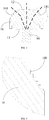
FIG. 1 is a schematic view of application of an existing lampshade structure. -
FIG. 2 is a three-dimensional schematic view of a lampshade structure according to an exemplary embodiment of the present invention. -
FIG. 3 is a side view of a lampshade structure according to an exemplary embodiment of the present invention. -
FIG. 4 is a schematic enlarged view of A inFIG. 3 . -
FIG. 5 is a top view of a lampshade structure according to an exemplary embodiment of the present invention. -
FIG. 6 is a schematic enlarged view of B inFIG. 5 . -
FIG. 7 andFIG. 8 are schematic views illustrating a structure in which a lampshade structure is applied to a UAV arm according to an exemplary embodiment of the present invention. - The following clearly and completely describes the technical solutions in the embodiments of the present invention with reference to accompanying drawings in the embodiments of the present invention. Apparently, the described embodiments are merely a part rather than all of the embodiments of the present invention. All other embodiments obtained by a person of ordinary skill in the art based on the embodiments of the present invention without creative efforts shall fall within the protection scope of the present invention.
- Light emitted by an LED indicator lamp generally covers a whole hemispherical space. The light has the maximum intensity in the normal direction, and gradually becomes weaker as it deviates from the normal direction. Therefore, the light intensity right below the indicator lamp, which is 0.9 cd, is generally about 10% that of the normal direction. As shown in
FIG. 1 , using a UAV as an example, if a height h of the UAV is 100 m and a maximum light-emitting angle of a conventional lampshade design in a vertical direction is -25°, in order to allow an observer to see high-intensity light, a horizontal distance L from the UAV to the observer is required to be greater than 214 m. As a result, the effect of the indicator lamp is greatly restricted. - The following describes a lampshade structure, a UAV arm, a UAV, and a movable platform of the present invention in detail with reference to the accompanying drawings. If there is no conflict, the following embodiments and features in implementations may be mutually combined.
- As shown in
FIG. 2 to FIG. 6 , an embodiment of the present invention provides alampshade structure 100, including: alampshade body 10. Thelampshade body 10 includes a first light-transmittingsurface 11 close to a light-emittingelement 90 and a second light-transmittingsurface 12 away from the light-emittingelement 90. The first light-transmittingsurface 11 is provided with ascattering structure 20 for outwardly refracting light emitted by the light-emittingelement 90. Thescattering structure 20 is provided with a first scatteringsurface 21 for outwardly refracting the light emitted by the light-emittingelement 90. In this embodiment, thescattering structure 20 is used for downwardly refracting the light emitted by the light-emittingelement 90. In this case, the light emitted by the light-emittingelement 90 is refracted by thescattering structure 20 after passing through the first light-transmittingsurface 11 and is then sent out from the second light-transmittingsurface 12. A refraction direction of the light is shown by the dashed line inFIG. 2 , to expand a light-emitting angle of the light along a vertical direction. Optionally, thelampshade body 10 may be made of optical plastic and may have a light transmittance of 97% or higher. The light-emittingelement 90 may be an LED lamp or an indicator lamp of other types. Certainly, in other examples, thescattering structure 20 may alternatively be used for refracting the light emitted by the light-emittingelement 90 towards two sides thereof along a horizontal direction, or refracting the light emitted by the light-emittingelement 90 upwardly along an upper portion of the body, which is not limited in the present invention. - As can be learned from the technical solution above, in the embodiment of the present invention, the light emitted by the light-emitting
element 90 is refracted outwardly by thescattering structure 20 arranged on thelampshade body 10, to expand a light-emitting angle and an irradiation direction of the light-emittingelement 90, thereby obtaining sufficient light in a desired direction. - In an optional implementation, the
scattering structure 20 includes at least onefirst scattering surface 21 for downwardly refracting light emitted by the light-emittingelement 90. In the example shown in the figure, thefirst scattering surface 21 is a plane, and there is onefirst scattering surface 21. Thefirst scattering surface 21 is arranged obliquely relative to a vertical surface. Thefirst scattering surface 21 includes anupper edge portion 211 and alower edge portion 212. Theupper edge portion 211 is away from the light-emittingelement 90, and thelower edge portion 212 is close to the light-emittingelement 90. Optionally, an oblique angle α between thefirst scattering surface 21 and the vertical surface is 20° to 25°. In this embodiment, the oblique angle α between thefirst scattering surface 21 and the vertical surface is 22.5°. Certainly, in other examples, there may be multiplefirst scattering surfaces 21 that are arranged obliquely relative to each other, or thefirst scattering surface 21 may be a spherical surface or a hemispherical surface. In both cases, the light emitted by the light-emittingelement 90 can be refracted at different refraction angles, to expand the light-emitting angle and the irradiation direction of the light-emittingelement 90. - In an optional implementation, the
lampshade body 10 is provided with asecond scattering surface 131 for outwardly refracting light refracted by thescattering structure 20. In this embodiment, thesecond scattering surface 131 is used for downwardly refracting, along the vertical direction, the light emitted by the light-emittingelement 90, where a refraction direction of the light is shown by the dashed line inFIG. 2 , so that in the vertical direction, the light-emittingelement 90 can achieve a maximum light-emitting angle of -90° and a light intensity of 1.3 cd. Optionally, thesecond scattering surface 131 is a step-like structure, so that light refracted by thefirst scattering surface 21 of thescattering structure 20 can obtain more refraction angles and directions, thereby further expanding the light-emitting angle and the irradiation direction of the light-emittingelement 90, to obtain sufficient light in the desired direction. Certainly, in other examples, thesecond scattering surface 131 may alternatively be a spherical surface or a hemispherical surface, and in this case, light refracted by thefirst scattering surface 21 of thescattering structure 20 can also obtain more refraction angles and directions, thereby expanding the light-emitting angle and the irradiation direction of the light-emittingelement 90. - In an optional implementation, the
lampshade body 10 is a quadrangular frustum structure, and an area of the first light-transmittingsurface 11 is larger than an area of the second light-transmittingsurface 12. In this embodiment, the quadrangular frustum structure includes twofirst sides 13 located on two sides of thelampshade body 10 along the vertical direction (as shown by direction Y inFIG. 1 ) and twosecond sides 14 located on two sides of thelampshade body 10 along the horizontal direction (as shown by direction X inFIG. 1 ). Thesecond scattering surface 131 may be arranged on thefirst side 13 at the bottom of thelampshade body 10. Certainly, in other embodiments, thefirst side 13 at the top of thelampshade body 10 may also be provided with thesecond scattering surface 131, to expand the light-emitting angle and the irradiation direction of the light-emittingelement 90. In addition, thelampshade body 10 may be other structures, for example, a truncated pyramid structure with a circular base or a truncated pyramid structure with a triangular base provided that the light-emitting angle and the irradiation direction of the light-emittingelement 90 along the vertical direction and the horizontal direction can be expanded. This is not limited in the present invention. - When there are multiple first scattering surfaces 21, the
first sides 13 are arranged corresponding to the first scattering surfaces 21, so that light refracted by the first scattering surfaces 21 is scattered by the first side to a desired direction. - In an optional implementation, the two
second sides 14 are each provided with athird scattering surface 141 for outwardly refracting the light refracted by thefirst scattering surface 21 of thescattering structure 20. In this embodiment, thethird scattering surface 141 is a step-like structure, so that the light refracted by thefirst scattering surface 21 of thescattering structure 20 can obtain more refraction angles and directions, thereby further expanding the light-emitting angle and the irradiation direction of the light-emittingelement 90, to obtain sufficient light in the desired direction. It may be appreciated that, thethird scattering surface 141 is used for outwardly refracting, along the horizontal direction, the light refracted by thefirst scattering surface 21 of thescattering structure 20, where a refraction direction of the light is shown by the dashed line inFIG. 3 , so that a maximum light-emitting angle of the light-emittingelement 90 along the horizontal direction can reach ±60°, that is, a full range in the horizontal direction can reach 120°. In this way, the light-emitting angle and the irradiation direction of the light-emittingelement 90 along the horizontal direction can be further expanded, to obtain sufficient light in the desired direction. Certainly, in other examples, thethird scattering surface 141 may alternatively be a spherical surface or a hemispherical surface, and in this case, the light refracted by thefirst scattering surface 21 of thescattering structure 20 can also obtain more refraction angles and directions, thereby expanding the light-emitting angle and the irradiation direction of the light-emittingelement 90. - In an optional implementation, in the example shown in the figure, the step-like structures of the
second scattering surface 131 and thethird scattering surface 141 each include lateral step surfaces and longitudinal step surfaces. The lateral step surfaces and the longitudinal step surfaces of thesecond scattering surface 131 are all arranged slightly obliquely relative to a horizontal plane, to change the light-emitting angle of the light-emittingelement 90. The lateral step surfaces of thethird scattering surface 141 are arranged along the horizontal direction, and the longitudinal step surfaces thereof are arranged along the vertical direction, so that the light-emitting angle of the light-emittingelement 90 can also be changed. In other examples, the lateral step surfaces and the longitudinal step surfaces of thethird scattering surface 141 may also be arranged slightly obliquely relative to the horizontal plane. The lateral step surfaces of thesecond scattering surface 131 may also be arranged along the horizontal direction, and the longitudinal step surfaces thereof may also be arranged along the vertical direction. This may be set according to actual requirements, and is not limited in the present invention. - In the example shown in the figure, in the step-like structure of the
second scattering surface 131 and the step-like structure of thethird scattering surface 141, step surfaces are arranged equidistant, and the distances between any two adjacent step surfaces in the two structures are equal to each other. In other examples, in the step-like structure of thesecond scattering surface 131 and the step-like structure of thethird scattering surface 141, step surfaces may be unevenly distributed, and the distances between any two adjacent step surfaces in the two structures may be set to different values. This may be set according to actual requirements, and is not limited in the present invention. - In addition, the step surfaces of the step-like structures of the two second scattering surfaces 131 may be arranged at different oblique angles relative to the horizontal direction. Likewise, the step surfaces of the step-like structures of the two third scattering surfaces 141 may be arranged at different oblique angles relative to the horizontal direction. This may be set according to actual requirements, and is not limited in the present invention.
- In an optional implementation, the
lampshade structure 100 in this embodiment of the present invention may further include a reinforcingcover 30 arranged on the first light-transmittingsurface 11, and thescattering structure 20 is arranged on the reinforcingcover 30. The reinforcingcover 30 may reinforce the overall structural strength of thelampshade structure 100. It may be appreciated that, the light emitted by the light-emittingelement 90 enters the first light-transmittingsurface 11 after passing through a side surface, which is close to the light-emittingelement 90, of the reinforcingcover 30, and then is refracted by thefirst scattering surface 21 and sent out from the second light-transmittingsurface 12. In this embodiment, the reinforcingcover 30 may be made of the same optical plastic as thelampshade body 10, to ensure the stability of light refraction. - In an optional implementation, the
lampshade structure 100 in this embodiment of the present invention may further include a connectingmember 40 connected to an external structural member, the connectingmember 40 being arranged on the first light-transmittingsurface 11. In this embodiment, the connectingmember 40 may use a buckle structure. In other examples, the connectingmember 40 may be a structural member of another form, for example, a plug connector. - As shown in
FIG. 7 andFIG. 8 , an embodiment of the present invention further provides a UAV arm, including anarm motor 80, a light-emittingelement 90, and alampshade structure 100. The light-emittingelement 90 is arranged inside thearm motor 80, and thelampshade structure 100 is arranged at an end portion of thearm motor 80. It should be noted that, the description about thelampshade structure 100 in the foregoing embodiments and implementations is also applicable to the UAV arm of the present invention. In this embodiment, the light-emittingelement 90 may be an LED lamp or an indicator lamp of other types. - As can be learned from the technical solution above, in the embodiment of the present invention, light emitted by the light-emitting
element 90 is refracted outwards by the scatteringstructure 20 arranged on thelampshade body 10 of thelampshade structure 100, to expand a light-emitting angle and an irradiation direction of the light-emittingelement 90, so that sufficient light is obtained in a desired direction. A height required to allow an observer under a UAV to clearly see light of the indicator lamp is reduced, so that the UAV can be accurately seen by the observer underneath, thus improving the effect of the indicator lamp. - An embodiment of the present invention further provides a UAV, including an arm, an
arm motor 80, a light-emittingelement 90, and alampshade structure 100. Thearm motor 80 is arranged on the arm, the light-emittingelement 90 is arranged inside thearm motor 80, and thelampshade structure 100 is arranged at an end portion of thearm motor 80. It should be noted that, the description about thelampshade structure 100 in the foregoing embodiments and implementations is also applicable to the UAV of the present invention. In this embodiment, the light-emittingelement 90 may be an LED lamp or an indicator lamp of other types. - As can be learned from the technical solution above, in the embodiment of the present invention, light emitted by the light-emitting
element 90 is refracted outwards by the scatteringstructure 20 arranged on thelampshade body 10 of thelampshade structure 100, to expand a light-emitting angle and an irradiation direction of the light-emittingelement 90, so that sufficient light is obtained in a desired direction. A height required to allow an observer under a UAV to clearly see light of the indicator lamp is reduced, so that the UAV can be accurately seen by the observer underneath, thus improving the effect of the indicator lamp. - An embodiment of the present invention further provides a movable platform, including a carrier, a power unit, a light-emitting element, and a lampshade structure. The light-emitting element is arranged on the carrier, and the lampshade structure is arranged at an end portion of the carrier; the power unit provides power for the movable platform. It should be noted that, the description about the
lampshade structure 100 in the foregoing embodiment and implementation is also applicable to the movable platform of the present invention. In this embodiment, the light-emittingelement 90 may be an LED lamp or an indicator lamp of other types. Embodiments of the present invention provide a method for evaluating image feature points and a movable platform. The movable platform may be, for example, a UAV, an unmanned ship, an unmanned vehicle, or a robot, etc. The UAV may be, for example, a rotorcraft, such as a rotorcraft driven by multiple thrust units through air, and the embodiment of the present invention is not limited thereto. - As can be learned from the technical solution above, in the embodiment of the present invention, light emitted by the light-emitting
element 90 is refracted outwards by the scatteringstructure 20 arranged on thelampshade body 10 of thelampshade structure 100, to expand a light-emitting angle and an irradiation direction of the light-emittingelement 90, so that sufficient light is obtained in a desired direction, thereby improving the effect of the indicator lamp. - It should be noted that, in this specification, relationship terms such as first and second are only used to distinguish an entity or operation from another entity or operation, but do not necessarily require or imply that there is any actual relationship or order between these entities or operations. In addition, terms "include", "comprise", or any other variations thereof are intended to cover non-exclusive inclusion, so that a process, a method, an article, or a device including a series of elements not only includes those elements, but also includes other elements that are not explicitly listed, or also includes elements inherent to the process, the method, the article, or the device. Without more restrictions, the elements defined by the phrase "including a ..." do not exclude the existence of other identical elements in the process, method, article, or device including the elements.
- The gimbal handle and the gimbal having the same provided in the embodiments of the present invention are described in detail above. Specific embodiments are used in this specification for illustration of the principles and implementation methods of the present invention. The description of these embodiments is merely used to help illustrate the method and its core concept of the present invention. Those of ordinary skill in the art may make modifications to the specific implementation methods and application scope according to the concept of the present invention. In conclusion, the content of the specification should not be construed as a limitation on the present invention.
Claims (52)
- A lampshade structure, characterized in that, including:a lampshade body,the lampshade body including a first light-transmitting surface close to a light-emitting element and a second light-transmitting surface away from the light-emitting element, wherein the first light-transmitting surface is provided with a scattering structure for outwardly refracting light emitted by the light-emitting element.
- The lampshade structure according to claim 1, characterized in that, wherein the scattering structure includes at least one first scattering surface for downwardly refracting the light emitted by the light-emitting element.
- The lampshade structure according to claim 2, characterized in that, wherein the first scattering surface is a plane, the first scattering surface is arranged obliquely relative to a vertical surface, the first scattering surface includes an upper edge portion and a lower edge portion, the upper edge portion is away from the light-emitting element, and the lower edge portion is close to the light-emitting element.
- The lampshade structure according to claim 3, characterized in that, wherein an oblique angle between the first scattering surface and the vertical surface is 20° to 25°.
- The lampshade structure according to claim 3, characterized in that, wherein multiple first scattering surfaces are provided, and the multiple first scattering surfaces are arranged obliquely relative to each other.
- The lampshade structure according to claim 1, characterized in that, wherein the first scattering surface is spherical or hemispherical.
- The lampshade structure according to claim 1, characterized in that, wherein the lampshade body is provided with a second scattering surface for outwardly refracting light refracted by the scattering structure.
- The lampshade structure according to claim 7, characterized in that, wherein the second scattering surface is a step-like structure.
- The lampshade structure according to claim 7, characterized in that, wherein the lampshade body is a quadrangular frustum structure, and an area of the first light-transmitting surface is greater than an area of the second light-transmitting surface; the quadrangular frustum structure includes two first sides located on two sides of the lampshade body along a vertical direction and two second sides located on two sides of the lampshade body along a horizontal direction; and the second scattering surface is arranged on the first side located at a bottom of the lampshade body.
- The lampshade structure according to claim 9, characterized in that, wherein the second side is provided with a third scattering surface for outwardly refracting the light refracted by the scattering structure.
- The lampshade structure according to claim 10, characterized in that, wherein the third scattering surface is a step-like structure.
- The lampshade structure according to claim 1, characterized in that, further including a reinforcing cover arranged on the first light-transmitting surface, wherein the scattering structure is arranged on the reinforcing cover.
- The lampshade structure according to claim 1, characterized in that, further including a connecting member connected to an external structural member, the connecting member being arranged on the first light-transmitting surface.
- An unmanned aerial vehicle (UAV) arm, characterized in that, including: an arm motor, a light-emitting element, and a lampshade structure, the light-emitting element being arranged inside the arm motor, and the lampshade structure being arranged at an end portion of the arm motor;
wherein the lampshade structure includes a lampshade body, the lampshade body includes a first light-transmitting surface close to the light-emitting element and a second light-transmitting surface away from the light-emitting element, and the first light-transmitting surface is provided with a scattering structure for outwardly refracting light emitted by the light-emitting element. - The lampshade structure according to claim 1, characterized in that, wherein the scattering structure includes at least one first scattering surface for downwardly refracting the light emitted by the light-emitting element.
- The lampshade structure according to claim 2, characterized in that, wherein the first scattering surface is a plane, the first scattering surface is arranged obliquely relative to a vertical surface, the first scattering surface includes an upper edge portion and a lower edge portion, the upper edge portion is away from the light-emitting element, and the lower edge portion is close to the light-emitting element.
- The lampshade structure according to claim 3, characterized in that, wherein an oblique angle between the first scattering surface and the vertical surface is 20° to 25°.
- The lampshade structure according to claim 3, characterized in that, wherein multiple first scattering surfaces are provided, and the multiple first scattering surfaces are arranged obliquely relative to each other.
- The lampshade structure according to claim 1, characterized in that, wherein the first scattering surface is spherical or hemispherical.
- The lampshade structure according to claim 1, characterized in that, wherein the lampshade body is provided with a second scattering surface for outwardly refracting light refracted by the scattering structure.
- The lampshade structure according to claim 7, characterized in that, wherein the second scattering surface is a step-like structure.
- The lampshade structure according to claim 7, characterized in that, wherein the lampshade body is a quadrangular frustum structure, and an area of the first light-transmitting surface is greater than an area of the second light-transmitting surface; the quadrangular frustum structure includes two first sides located on two sides of the lampshade body along a vertical direction and two second sides located on two sides of the lampshade body along a horizontal direction; and the second scattering surface is arranged on the first side located at a bottom of the lampshade body.
- The lampshade structure according to claim 9, characterized in that, wherein the second side is provided with a third scattering surface for outwardly refracting the light refracted by the scattering structure.
- The lampshade structure according to claim 10, characterized in that, wherein the third scattering surface is a step-like structure.
- The lampshade structure according to claim 1, characterized in that, further including a reinforcing cover arranged on the first light-transmitting surface, wherein the scattering structure is arranged on the reinforcing cover.
- The lampshade structure according to claim 1, characterized in that, further including a connecting member connected to an external structural member, the connecting member being arranged on the first light-transmitting surface.
- An unmanned aerial vehicle (UAV), characterized in that, including: an arm, an arm motor, a light-emitting element, and a lampshade structure, the light-emitting element being arranged inside the arm motor, and the lampshade structure being arranged at an end portion of the arm motor;
wherein the lampshade structure includes a lampshade body, the lampshade body includes a first light-transmitting surface close to the light-emitting element and a second light-transmitting surface away from the light-emitting element, and the first light-transmitting surface is provided with a scattering structure for outwardly refracting light emitted by the light-emitting element. - The lampshade structure according to claim 1, characterized in that, wherein the scattering structure includes at least one first scattering surface for downwardly refracting the light emitted by the light-emitting element.
- The lampshade structure according to claim 2, characterized in that, wherein the first scattering surface is a plane, the first scattering surface is arranged obliquely relative to a vertical surface, the first scattering surface includes an upper edge portion and a lower edge portion, the upper edge portion is away from the light-emitting element, and the lower edge portion is close to the light-emitting element.
- The lampshade structure according to claim 3, characterized in that, wherein an oblique angle between the first scattering surface and the vertical surface is 20° to 25°.
- The lampshade structure according to claim 3, characterized in that, wherein multiple first scattering surfaces are provided, and the multiple first scattering surfaces are arranged obliquely relative to each other.
- The lampshade structure according to claim 1, characterized in that, wherein the first scattering surface is spherical or hemispherical.
- The lampshade structure according to claim 1, characterized in that, wherein the lampshade body is provided with a second scattering surface for outwardly refracting light refracted by the scattering structure.
- The lampshade structure according to claim 7, characterized in that, wherein the second scattering surface is a step-like structure.
- The lampshade structure according to claim 7, characterized in that, wherein the lampshade body is a quadrangular frustum structure, and an area of the first light-transmitting surface is greater than an area of the second light-transmitting surface; the quadrangular frustum structure includes two first sides located on two sides of the lampshade body along a vertical direction and two second sides located on two sides of the lampshade body along a horizontal direction; and the second scattering surface is arranged on the first side located at a bottom of the lampshade body.
- The lampshade structure according to claim 9, characterized in that, wherein the second side is provided with a third scattering surface for outwardly refracting the light refracted by the scattering structure.
- The unmanned aerial vehicle (UAV) according to claim 10, characterized in that, wherein the third scattering surface is a step-like structure.
- The lampshade structure according to claim 1, characterized in that, further including a reinforcing cover arranged on the first light-transmitting surface, wherein the scattering structure is arranged on the reinforcing cover.
- The lampshade structure according to claim 1, characterized in that, further including a connecting member connected to an external structural member, the connecting member being arranged on the first light-transmitting surface.
- A movable platform, characterized in that, including: a carrier, a power unit, a light-emitting element and a lampshade structure, the light-emitting element being arranged on the carrier, the lampshade structure being arranged at an end portion of the carrier, and the power unit providing power for the movable platform;
wherein the lampshade structure includes a lampshade body, the lampshade body includes a first light-transmitting surface close to the light-emitting element and a second light-transmitting surface away from the light-emitting element, and the first light-transmitting surface is provided with a scattering structure for outwardly refracting light emitted by the light-emitting element. - The lampshade structure according to claim 1, characterized in that, wherein the scattering structure includes at least one first scattering surface for downwardly refracting the light emitted by the light-emitting element.
- The lampshade structure according to claim 2, characterized in that, wherein the first scattering surface is a plane, the first scattering surface is arranged obliquely relative to a vertical surface, the first scattering surface includes an upper edge portion and a lower edge portion, the upper edge portion is away from the light-emitting element, and the lower edge portion is close to the light-emitting element.
- The lampshade structure according to claim 3, characterized in that, wherein an oblique angle between the first scattering surface and the vertical surface is 20° to 25°.
- The lampshade structure according to claim 3, characterized in that, wherein multiple first scattering surfaces are provided, and the multiple first scattering surfaces are arranged obliquely relative to each other.
- The lampshade structure according to claim 1, characterized in that, wherein the first scattering surface is spherical or hemispherical.
- The lampshade structure according to claim 1, characterized in that, wherein the lampshade body is provided with a second scattering surface for outwardly refracting light refracted by the scattering structure.
- The lampshade structure according to claim 7, characterized in that, wherein the second scattering surface is a step-like structure.
- The lampshade structure according to claim 7, characterized in that, wherein the lampshade body is a quadrangular frustum structure, and an area of the first light-transmitting surface is greater than an area of the second light-transmitting surface; the quadrangular frustum structure includes two first sides located on two sides of the lampshade body along a vertical direction and two second sides located on two sides of the lampshade body along a horizontal direction; and the second scattering surface is arranged on the first side located at a bottom of the lampshade body.
- The lampshade structure according to claim 9, characterized in that, wherein the second side is provided with a third scattering surface for outwardly refracting the light refracted by the scattering structure.
- The lampshade structure according to claim 10, characterized in that, wherein the third scattering surface is a step-like structure.
- The lampshade structure according to claim 1, characterized in that, further including a reinforcing cover arranged on the first light-transmitting surface, wherein the scattering structure is arranged on the reinforcing cover.
- The lampshade structure according to claim 1, characterized in that, further including a connecting member connected to an external structural member, the connecting member being arranged on the first light-transmitting surface.
Applications Claiming Priority (1)
| Application Number | Priority Date | Filing Date | Title |
|---|---|---|---|
| PCT/CN2018/119237 WO2020113444A1 (en) | 2018-12-04 | 2018-12-04 | Lampshade structure, unmanned aerial vehicle arm, unmanned aerial vehicle and movable platform |
Publications (2)
| Publication Number | Publication Date |
|---|---|
| EP3805109A1 true EP3805109A1 (en) | 2021-04-14 |
| EP3805109A4 EP3805109A4 (en) | 2021-09-01 |
Family
ID=69438492
Family Applications (1)
| Application Number | Title | Priority Date | Filing Date |
|---|---|---|---|
| EP18942226.4A Withdrawn EP3805109A4 (en) | 2018-12-04 | 2018-12-04 | SHADE STRUCTURE, UNPILOT AIR VEHICLE ARM, UNPILOT AIR VEHICLE AND MOBILE PLATFORM |
Country Status (4)
| Country | Link |
|---|---|
| US (1) | US11383856B2 (en) |
| EP (1) | EP3805109A4 (en) |
| CN (1) | CN110799421A (en) |
| WO (1) | WO2020113444A1 (en) |
Families Citing this family (3)
| Publication number | Priority date | Publication date | Assignee | Title |
|---|---|---|---|---|
| WO2022095051A1 (en) * | 2020-11-09 | 2022-05-12 | 深圳市大疆创新科技有限公司 | Arm and rack for unmanned aerial vehicle, and unmanned aerial vehicle |
| CN115570540B (en) * | 2021-07-06 | 2025-12-05 | 南京泉峰科技有限公司 | Power tools |
| CN220721406U (en) * | 2022-06-09 | 2024-04-05 | 影石创新科技股份有限公司 | Unmanned aerial vehicle |
Family Cites Families (35)
| Publication number | Priority date | Publication date | Assignee | Title |
|---|---|---|---|---|
| IT1160893B (en) * | 1978-10-30 | 1987-03-11 | Iao Industrie Riunite Spa | MOTORCYCLE LIGHT |
| US4929866A (en) * | 1987-11-17 | 1990-05-29 | Mitsubishi Cable Industries, Ltd. | Light emitting diode lamp |
| US5897196A (en) * | 1996-03-29 | 1999-04-27 | Osram Sylvania Inc. | Motor vehicle headlamp |
| US6981784B2 (en) * | 2002-05-30 | 2006-01-03 | Gelcore, Llc | Side projecting LED signal |
| US7040786B2 (en) * | 2002-10-04 | 2006-05-09 | Goodrich Hella Aerospace Lighting Systems Gmbh | Anticollision light for aircraft |
| JP4290585B2 (en) * | 2004-02-26 | 2009-07-08 | 株式会社小糸製作所 | Vehicle lighting |
| CN100582559C (en) * | 2006-12-19 | 2010-01-20 | 财团法人工业技术研究院 | Light emitting device capable of adjusting light emitting angle |
| JP4663680B2 (en) * | 2007-05-22 | 2011-04-06 | 豊田合成株式会社 | Vehicle lighting |
| CN101539266B (en) * | 2008-03-19 | 2011-05-11 | 富准精密工业(深圳)有限公司 | Luminous element and lens thereof |
| TW201011349A (en) * | 2008-09-10 | 2010-03-16 | E Pin Optical Industry Co Ltd | Plano-Fresnel LED lens for angular distribution patterns and LED assembly thereof |
| TWI364120B (en) * | 2008-09-10 | 2012-05-11 | E Pin Optical Industry Co Ltd | Convex-fresnel led lens for angular distribution patterns and led assembly thereof |
| US8662721B2 (en) * | 2009-11-26 | 2014-03-04 | Nathan Howard Calvin | Aircraft external lighting system and method |
| CN201688165U (en) * | 2010-03-15 | 2010-12-29 | 邢智勇 | Angle-adjustable LED illuminating lamp |
| CN101881387A (en) * | 2010-06-10 | 2010-11-10 | 鸿富锦精密工业(深圳)有限公司 | LED fluorescent lamp |
| CN201954462U (en) * | 2011-01-31 | 2011-08-31 | 李洲科技股份有限公司 | Light source lens structure |
| CN202216023U (en) * | 2011-09-02 | 2012-05-09 | 林松涛 | LED illuminating lamp |
| JP5486052B2 (en) * | 2012-07-20 | 2014-05-07 | ヤマハ発動機株式会社 | Unmanned helicopter |
| CN102788309B (en) * | 2012-08-10 | 2014-01-29 | 霍永峰 | a lampshade |
| US9677738B2 (en) * | 2013-03-15 | 2017-06-13 | 1947796 Ontario Inc. | Optical device and system for solid-state lighting |
| EP2801749B1 (en) * | 2013-05-07 | 2021-09-15 | Goodrich Lighting Systems GmbH | LED light unit and method of replacing an LED light unit |
| TW201500775A (en) * | 2013-06-26 | 2015-01-01 | Hon Hai Prec Ind Co Ltd | Lens and light source device with the same |
| US20150217840A1 (en) * | 2014-02-04 | 2015-08-06 | Zachary Taylor | Light Altering Rub Rail and Rub Rail Insert |
| US9840820B2 (en) * | 2014-10-29 | 2017-12-12 | Zachary Taylor | Light altering bumper device |
| KR20160069671A (en) * | 2014-12-09 | 2016-06-17 | 엘지이노텍 주식회사 | Lens and light emitting device module including the same |
| CN106560653B (en) * | 2015-09-30 | 2020-06-23 | 西门子瑞士有限公司 | Lens, and light emitting apparatus and visual notification apparatus having the same |
| CN205524952U (en) * | 2016-01-29 | 2016-08-31 | 深圳市大疆创新科技有限公司 | Unmanned aerial vehicle and horn mechanism thereof |
| CN205524926U (en) * | 2016-01-29 | 2016-08-31 | 深圳市大疆创新科技有限公司 | Lamp shade and use horn structure, unmanned aerial vehicle of this lamp shade |
| US10132476B2 (en) * | 2016-03-08 | 2018-11-20 | Lilibrand Llc | Lighting system with lens assembly |
| CN205535348U (en) * | 2016-03-30 | 2016-08-31 | 邹小锋 | Wall lamp and lamp shade thereof |
| JP6843547B2 (en) * | 2016-08-05 | 2021-03-17 | 株式会社エンプラス | Luminous flux control member, light emitting device and lighting device |
| CN107776867B (en) * | 2016-08-31 | 2023-03-07 | 臻迪科技股份有限公司 | Unmanned aerial vehicle horn device |
| CN106662313A (en) * | 2016-09-27 | 2017-05-10 | 深圳市大疆创新科技有限公司 | Navigation lights for UAVs and UAVs |
| US10569693B2 (en) * | 2017-05-31 | 2020-02-25 | Grote Industries, Inc. | Electric lamp having a cover with a light guide |
| CN207389548U (en) * | 2017-09-27 | 2018-05-22 | 广东澄星无人机股份有限公司 | A kind of replaceable lampshade unmanned plane |
| CN207529081U (en) * | 2017-09-30 | 2018-06-22 | 维沃移动通信有限公司 | A kind of flash lamp module and mobile terminal |
-
2018
- 2018-12-04 EP EP18942226.4A patent/EP3805109A4/en not_active Withdrawn
- 2018-12-04 WO PCT/CN2018/119237 patent/WO2020113444A1/en not_active Ceased
- 2018-12-04 CN CN201880041364.0A patent/CN110799421A/en active Pending
-
2020
- 2020-12-14 US US17/121,737 patent/US11383856B2/en active Active
Also Published As
| Publication number | Publication date |
|---|---|
| US11383856B2 (en) | 2022-07-12 |
| EP3805109A4 (en) | 2021-09-01 |
| WO2020113444A1 (en) | 2020-06-11 |
| US20210094702A1 (en) | 2021-04-01 |
| CN110799421A (en) | 2020-02-14 |
Similar Documents
| Publication | Publication Date | Title |
|---|---|---|
| US11383856B2 (en) | Lampshade structures, unmanned aerial vehicle arms, unmanned aerial vehicles, and movable platforms | |
| CA2303007C (en) | Illuminating lens designed by extrinsic differential geometry | |
| JPWO2008023797A1 (en) | Lighting device | |
| US9080739B1 (en) | System for producing a slender illumination pattern from a light emitting diode | |
| CN106560653A (en) | Lens, lighting equipment having same, and visual notification appliance | |
| KR20110010055A (en) | Reflective cover and lighting device | |
| US10520163B2 (en) | Light bundle control member, light emitting device, and illuminating device | |
| US20150292703A1 (en) | Rear lamp for vehicle | |
| CN110972475A (en) | Lens structure, night navigation lamp and unmanned vehicles | |
| US11421853B2 (en) | Light distribution module | |
| JP2016195072A (en) | Lamp | |
| US20150276179A1 (en) | Led module and lens mounted thereon | |
| JP6589293B2 (en) | Lighting fixtures and lenses | |
| JP6858015B2 (en) | Illuminator | |
| TWI600858B (en) | Illuminating device | |
| EP3135590B1 (en) | Systems and methods for anti-collision lights | |
| US9243763B2 (en) | Beacon light optic, beacon light, method for obtaining a beacon light optic | |
| CN102401317A (en) | Light collecting lens with multi-curvature combined curved surface, light collecting module and lamp | |
| CN209355168U (en) | Lampshade structure, unmanned plane horn, unmanned plane and moveable platform | |
| WO2021008021A1 (en) | Lighting device and optical device having the same | |
| CN111742175A (en) | Light beam control part, light-emitting device and lighting device | |
| JP2006196931A (en) | Lens-integrated light emitting device | |
| CN206072930U (en) | A kind of illuminator of rescue helicopters | |
| CN206890272U (en) | On-vehicle machines people | |
| CN118423646A (en) | Optical component, lamp, vehicle and method for manufacturing optical component |
Legal Events
| Date | Code | Title | Description |
|---|---|---|---|
| STAA | Information on the status of an ep patent application or granted ep patent |
Free format text: STATUS: THE INTERNATIONAL PUBLICATION HAS BEEN MADE |
|
| PUAI | Public reference made under article 153(3) epc to a published international application that has entered the european phase |
Free format text: ORIGINAL CODE: 0009012 |
|
| STAA | Information on the status of an ep patent application or granted ep patent |
Free format text: STATUS: REQUEST FOR EXAMINATION WAS MADE |
|
| 17P | Request for examination filed |
Effective date: 20201015 |
|
| AK | Designated contracting states |
Kind code of ref document: A1 Designated state(s): AL AT BE BG CH CY CZ DE DK EE ES FI FR GB GR HR HU IE IS IT LI LT LU LV MC MK MT NL NO PL PT RO RS SE SI SK SM TR |
|
| AX | Request for extension of the european patent |
Extension state: BA ME |
|
| A4 | Supplementary search report drawn up and despatched |
Effective date: 20210802 |
|
| RIC1 | Information provided on ipc code assigned before grant |
Ipc: B64D 47/06 20060101AFI20210727BHEP Ipc: F21V 3/02 20060101ALI20210727BHEP Ipc: B64C 1/06 20060101ALI20210727BHEP Ipc: B63B 45/02 20060101ALI20210727BHEP Ipc: B63B 35/00 20200101ALI20210727BHEP Ipc: B64C 39/02 20060101ALI20210727BHEP Ipc: B64D 47/02 20060101ALI20210727BHEP Ipc: F21S 43/20 20180101ALI20210727BHEP Ipc: F21Y 115/10 20160101ALI20210727BHEP |
|
| DAV | Request for validation of the european patent (deleted) | ||
| DAX | Request for extension of the european patent (deleted) | ||
| STAA | Information on the status of an ep patent application or granted ep patent |
Free format text: STATUS: EXAMINATION IS IN PROGRESS |
|
| 17Q | First examination report despatched |
Effective date: 20220502 |
|
| STAA | Information on the status of an ep patent application or granted ep patent |
Free format text: STATUS: THE APPLICATION HAS BEEN WITHDRAWN |
|
| 18W | Application withdrawn |
Effective date: 20220830 |