EP3804996A1 - Inkjet recording apparatus - Google Patents
Inkjet recording apparatus Download PDFInfo
- Publication number
- EP3804996A1 EP3804996A1 EP20201107.8A EP20201107A EP3804996A1 EP 3804996 A1 EP3804996 A1 EP 3804996A1 EP 20201107 A EP20201107 A EP 20201107A EP 3804996 A1 EP3804996 A1 EP 3804996A1
- Authority
- EP
- European Patent Office
- Prior art keywords
- conveyor belt
- opening portion
- paper
- recording medium
- size
- Prior art date
- Legal status (The legal status is an assumption and is not a legal conclusion. Google has not performed a legal analysis and makes no representation as to the accuracy of the status listed.)
- Granted
Links
Images







Classifications
-
- B—PERFORMING OPERATIONS; TRANSPORTING
- B41—PRINTING; LINING MACHINES; TYPEWRITERS; STAMPS
- B41J—TYPEWRITERS; SELECTIVE PRINTING MECHANISMS, i.e. MECHANISMS PRINTING OTHERWISE THAN FROM A FORME; CORRECTION OF TYPOGRAPHICAL ERRORS
- B41J2/00—Typewriters or selective printing mechanisms characterised by the printing or marking process for which they are designed
- B41J2/005—Typewriters or selective printing mechanisms characterised by the printing or marking process for which they are designed characterised by bringing liquid or particles selectively into contact with a printing material
- B41J2/01—Ink jet
- B41J2/135—Nozzles
- B41J2/165—Prevention or detection of nozzle clogging, e.g. cleaning, capping or moistening for nozzles
- B41J2/16517—Cleaning of print head nozzles
- B41J2/1652—Cleaning of print head nozzles by driving a fluid through the nozzles to the outside thereof, e.g. by applying pressure to the inside or vacuum at the outside of the print head
- B41J2/16526—Cleaning of print head nozzles by driving a fluid through the nozzles to the outside thereof, e.g. by applying pressure to the inside or vacuum at the outside of the print head by applying pressure only
-
- B—PERFORMING OPERATIONS; TRANSPORTING
- B41—PRINTING; LINING MACHINES; TYPEWRITERS; STAMPS
- B41J—TYPEWRITERS; SELECTIVE PRINTING MECHANISMS, i.e. MECHANISMS PRINTING OTHERWISE THAN FROM A FORME; CORRECTION OF TYPOGRAPHICAL ERRORS
- B41J2/00—Typewriters or selective printing mechanisms characterised by the printing or marking process for which they are designed
- B41J2/005—Typewriters or selective printing mechanisms characterised by the printing or marking process for which they are designed characterised by bringing liquid or particles selectively into contact with a printing material
- B41J2/01—Ink jet
- B41J2/135—Nozzles
- B41J2/165—Prevention or detection of nozzle clogging, e.g. cleaning, capping or moistening for nozzles
- B41J2/16517—Cleaning of print head nozzles
- B41J2/1652—Cleaning of print head nozzles by driving a fluid through the nozzles to the outside thereof, e.g. by applying pressure to the inside or vacuum at the outside of the print head
-
- B—PERFORMING OPERATIONS; TRANSPORTING
- B41—PRINTING; LINING MACHINES; TYPEWRITERS; STAMPS
- B41J—TYPEWRITERS; SELECTIVE PRINTING MECHANISMS, i.e. MECHANISMS PRINTING OTHERWISE THAN FROM A FORME; CORRECTION OF TYPOGRAPHICAL ERRORS
- B41J2/00—Typewriters or selective printing mechanisms characterised by the printing or marking process for which they are designed
- B41J2/005—Typewriters or selective printing mechanisms characterised by the printing or marking process for which they are designed characterised by bringing liquid or particles selectively into contact with a printing material
- B41J2/01—Ink jet
-
- B—PERFORMING OPERATIONS; TRANSPORTING
- B41—PRINTING; LINING MACHINES; TYPEWRITERS; STAMPS
- B41J—TYPEWRITERS; SELECTIVE PRINTING MECHANISMS, i.e. MECHANISMS PRINTING OTHERWISE THAN FROM A FORME; CORRECTION OF TYPOGRAPHICAL ERRORS
- B41J11/00—Devices or arrangements of selective printing mechanisms, e.g. ink-jet printers or thermal printers, for supporting or handling copy material in sheet or web form
- B41J11/007—Conveyor belts or like feeding devices
-
- B—PERFORMING OPERATIONS; TRANSPORTING
- B41—PRINTING; LINING MACHINES; TYPEWRITERS; STAMPS
- B41J—TYPEWRITERS; SELECTIVE PRINTING MECHANISMS, i.e. MECHANISMS PRINTING OTHERWISE THAN FROM A FORME; CORRECTION OF TYPOGRAPHICAL ERRORS
- B41J13/00—Devices or arrangements of selective printing mechanisms, e.g. ink-jet printers or thermal printers, specially adapted for supporting or handling copy material in short lengths, e.g. sheets
- B41J13/0009—Devices or arrangements of selective printing mechanisms, e.g. ink-jet printers or thermal printers, specially adapted for supporting or handling copy material in short lengths, e.g. sheets control of the transport of the copy material
- B41J13/0018—Devices or arrangements of selective printing mechanisms, e.g. ink-jet printers or thermal printers, specially adapted for supporting or handling copy material in short lengths, e.g. sheets control of the transport of the copy material in the sheet input section of automatic paper handling systems
-
- B—PERFORMING OPERATIONS; TRANSPORTING
- B41—PRINTING; LINING MACHINES; TYPEWRITERS; STAMPS
- B41J—TYPEWRITERS; SELECTIVE PRINTING MECHANISMS, i.e. MECHANISMS PRINTING OTHERWISE THAN FROM A FORME; CORRECTION OF TYPOGRAPHICAL ERRORS
- B41J2/00—Typewriters or selective printing mechanisms characterised by the printing or marking process for which they are designed
- B41J2/005—Typewriters or selective printing mechanisms characterised by the printing or marking process for which they are designed characterised by bringing liquid or particles selectively into contact with a printing material
- B41J2/01—Ink jet
- B41J2/135—Nozzles
- B41J2/165—Prevention or detection of nozzle clogging, e.g. cleaning, capping or moistening for nozzles
- B41J2/16517—Cleaning of print head nozzles
-
- B—PERFORMING OPERATIONS; TRANSPORTING
- B41—PRINTING; LINING MACHINES; TYPEWRITERS; STAMPS
- B41J—TYPEWRITERS; SELECTIVE PRINTING MECHANISMS, i.e. MECHANISMS PRINTING OTHERWISE THAN FROM A FORME; CORRECTION OF TYPOGRAPHICAL ERRORS
- B41J2/00—Typewriters or selective printing mechanisms characterised by the printing or marking process for which they are designed
- B41J2/005—Typewriters or selective printing mechanisms characterised by the printing or marking process for which they are designed characterised by bringing liquid or particles selectively into contact with a printing material
- B41J2/01—Ink jet
- B41J2/135—Nozzles
- B41J2/165—Prevention or detection of nozzle clogging, e.g. cleaning, capping or moistening for nozzles
- B41J2/16585—Prevention or detection of nozzle clogging, e.g. cleaning, capping or moistening for nozzles for paper-width or non-reciprocating print heads
-
- B—PERFORMING OPERATIONS; TRANSPORTING
- B41—PRINTING; LINING MACHINES; TYPEWRITERS; STAMPS
- B41J—TYPEWRITERS; SELECTIVE PRINTING MECHANISMS, i.e. MECHANISMS PRINTING OTHERWISE THAN FROM A FORME; CORRECTION OF TYPOGRAPHICAL ERRORS
- B41J2/00—Typewriters or selective printing mechanisms characterised by the printing or marking process for which they are designed
- B41J2/005—Typewriters or selective printing mechanisms characterised by the printing or marking process for which they are designed characterised by bringing liquid or particles selectively into contact with a printing material
- B41J2/01—Ink jet
- B41J2/17—Ink jet characterised by ink handling
- B41J2/1714—Conditioning of the outside of ink supply systems, e.g. inkjet collector cleaning, ink mist removal
-
- B—PERFORMING OPERATIONS; TRANSPORTING
- B41—PRINTING; LINING MACHINES; TYPEWRITERS; STAMPS
- B41J—TYPEWRITERS; SELECTIVE PRINTING MECHANISMS, i.e. MECHANISMS PRINTING OTHERWISE THAN FROM A FORME; CORRECTION OF TYPOGRAPHICAL ERRORS
- B41J2/00—Typewriters or selective printing mechanisms characterised by the printing or marking process for which they are designed
- B41J2/005—Typewriters or selective printing mechanisms characterised by the printing or marking process for which they are designed characterised by bringing liquid or particles selectively into contact with a printing material
- B41J2/01—Ink jet
- B41J2/17—Ink jet characterised by ink handling
- B41J2/1721—Collecting waste ink; Collectors therefor
-
- B—PERFORMING OPERATIONS; TRANSPORTING
- B41—PRINTING; LINING MACHINES; TYPEWRITERS; STAMPS
- B41J—TYPEWRITERS; SELECTIVE PRINTING MECHANISMS, i.e. MECHANISMS PRINTING OTHERWISE THAN FROM A FORME; CORRECTION OF TYPOGRAPHICAL ERRORS
- B41J29/00—Details of, or accessories for, typewriters or selective printing mechanisms not otherwise provided for
- B41J29/38—Drives, motors, controls or automatic cut-off devices for the entire printing mechanism
-
- B—PERFORMING OPERATIONS; TRANSPORTING
- B41—PRINTING; LINING MACHINES; TYPEWRITERS; STAMPS
- B41J—TYPEWRITERS; SELECTIVE PRINTING MECHANISMS, i.e. MECHANISMS PRINTING OTHERWISE THAN FROM A FORME; CORRECTION OF TYPOGRAPHICAL ERRORS
- B41J2202/00—Embodiments of or processes related to ink-jet or thermal heads
- B41J2202/01—Embodiments of or processes related to ink-jet heads
- B41J2202/21—Line printing
Definitions
- the present disclosure relates to an inkjet recording apparatus that records an image by ejecting ink onto a recording medium.
- flushing for ejecting ink from the nozzles is regularly performed in order to reduce or prevent clogging of the nozzles due to drying of the ink.
- an opening portion is provided in a conveyor belt, and a recording medium is placed on the conveyor belt so as not to cover the opening portion and conveyed. Then, when the opening portion reaches a position facing the recording head due to the running of the conveyor belt ink is ejected from the nozzles of the recording head to perform flushing.
- An ink absorber such as a sponge or the like is arranged on the side opposite to the recording head (inner peripheral surface side) with respect to the conveyor belt, and ink that is ejected from the recording head and passed through the opening portion during flushing is absorbed by the ink absorber.
- a plurality of opening portions are provided in the conveyor belt in the conveying direction of the recording medium, and in a case where the size of the recording medium is large, the conveying speed of the recording medium is slowed to perform flushing.
- the conveying speed of the recording medium By decreasing the conveying speed of the recording medium, the number of rows in the conveying direction of the opening portions located between the recording media on the conveyor belt increases, so ejection defects may be reduced by increasing the ink ejection amount required for flushing.
- the position of the opening portions is recognized based on the detection result of a mark provided on the conveyor belt, and the ejection of ink in flushing is controlled to take into account deformation such as elongation of the conveyor belt and the like, whereby ink is more accurately passed through the opening portions.
- an inkjet recording apparatus includes a recording head and an endless conveyor belt.
- the recording head has a plurality of nozzles for ejecting ink.
- the endless conveyor belt conveys a recording medium to a position facing the recording head.
- the inkjet recording apparatus includes a recording medium supply unit and a control unit.
- the recording medium supply unit supplies the recording medium to the conveyor belt.
- the control unit together with causing the recording head to execute flushing for ejecting the ink at a timing different from timing that contributes to image formation on the recording medium, controls supply of the recording medium to the conveyor belt by the recording medium supply unit.
- the conveyor belt has a plurality of opening portion groups in which opening portions are arranged in a belt width direction perpendicular to the conveying direction of the recording medium.
- the opening portions allow ink ejected from each of the nozzles of the recording head to pass during the flushing.
- the control unit determines the pattern of the plurality of the opening portion groups used for the flushing in one cycle of the conveyor belt according to the size of the recording medium.
- the control unit causes the recording medium to be supplied from the recording medium supply unit between the plurality of opening groups arranged in the conveying direction in the pattern on the conveyor belt and at positions separated from the opening portion groups by a specific distance or more.
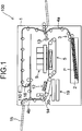
- FIG. 1 is an explanatory diagram illustrating a schematic configuration of a printer 100 as an inkjet recording apparatus according to an embodiment of the present disclosure.
- the printer 100 includes a paper feed cassette 2 that is a paper storage unit.
- the paper feed cassette 2 is arranged at the lower inner portion of the printer body 1.
- Paper P which is an example of a recording medium, is housed inside the paper feed cassette 2.
- a paper feeding device 3 is arranged on the downstream side in the paper conveying direction of the paper feed cassette 2, tor in other words, above the right side of the paper feed cassette 2 in FIG. 1 .
- paper P is directed toward the upper right of the paper feed cassette 2 in FIG. 1 , and is separated and fed out one sheet at a time.
- the printer 100 includes a first paper conveying path 4a in the inner portion thereof.
- the first paper conveying path 4a is located on the upper right side, which is the paper feed direction, with respect to the paper feed cassette 2.
- the paper P fed out from the paper feed cassette 2 is conveyed vertically upward along the side surface of the printer body 1 by the first paper conveying path 4a.
- a registration roller pair 13 is provided at the downstream end of the first paper conveying path 4a in the paper conveying direction. Furthermore, a first conveying unit 5 and the recording unit 9 are arranged immediately downstream of the registration roller pair 13 in the paper conveying direction. The paper P fed out from the paper feed cassette 2 reaches the registration roller pair 13 via the first paper conveying path 4a. The registration roller pair 13 feeds the paper P toward the first conveying unit 5 while correcting diagonal feeding of the paper P and measuring the timing with the ink ejection operation performed by the recording unit 9.
- the paper P fed to the first conveying unit 5 is conveyed to a position facing the recording unit 9 (especially recording heads 17a to 17c described later) by the first conveyor belt 8 (see FIG. 2 ).
- An image is recorded on the paper P by ejecting ink from the recording unit 9 onto the paper P.
- the control unit 110 includes, for example, a central processing unit (CPU).
- the second conveying unit 12 is arranged on the downstream side (left side in FIG. 1 ) of the first conveying unit 5 in the paper conveying direction.
- the paper P on which the image is recorded by the recording unit 9 is sent to the second conveying unit 12.
- the ink ejected onto the surface of the paper P is dried while passing through the second conveying unit 12.
- a decurler unit 14 is provided on the downstream side of the second conveying unit 12 in the paper conveying direction and near the left side surface of the printer body 1.
- the paper P whose ink has been dried by the second conveying unit 12 is sent to the decurler unit 14 in order to correct curling that has occurred in the paper P.
- a second paper conveying path 4b is provided on the downstream side (upper side in FIG. 1 ) of the decurler unit 14 in the paper conveying direction.
- paper P that has passed through the decurler unit 14 passes through the second paper conveying path 4b and is discharged to the paper discharge tray 15 provided in the outer portion of the left side surface of the printer 100.
- a reverse conveying path 16 for performing double-sided recording is provided in the upper portion of the printer body 1 above the recording unit 9 and the second conveying unit 12.
- the paper P that has passed through the second conveying unit 12 and the decurler unit 14 after recording on one surface (first surface) of the paper P is sent to the reverse conveying path 16 through the second paper conveying path 4b.
- the conveying direction of the paper P sent to the reverse conveying path 16 is subsequently switched for recording on the other surface (second surface) of the paper P. Then, the paper P passes through the upper portion of the printer body 1 and is sent toward the right side, and is sent again, via the registration roller pair 13, to the first conveying unit 5 with the second surface thereof facing upward. In the first conveying unit 5, the paper P is conveyed to a position facing the recording unit 9, and an image is recorded on the second surface by ejecting ink from the recording unit 9. The paper P after double-sided recording is discharged to the paper discharge tray 15 via the second conveying unit 12, the decurler unit 14, and the second paper conveying path 4b in this order.
- a maintenance unit 19 and a cap unit 20 are arranged below the second conveying unit 12.
- the maintenance unit 19 moves horizontally below the recording unit 9, wipes the ink extruded from the ink ejection port of the recording head, and collects the wiped ink.
- purging refers to an operation of forcibly extruding the ink from the ink ejection port of the recording head in order to discharge thickened ink, foreign matter and air bubbles in the ink ejection port.
- the cap unit 20 moves horizontally below the recording unit 9 when capping the ink ejection surface of the recording head, moves further upward, and is attached to the lower surface of the recording head.
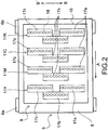
- FIG. 2 is a plan view of the recording unit 9.
- the recording unit 9 includes a head housing 10 and line heads 11Y, 11M, 11C and 11K.
- the line heads 11Y to 11K are held in the head housing 10 at a height at which specific spacing (for example, 1 mm) is formed with respect to the conveying surface of an endless first conveyor belt 8 that spans around a plurality of rollers including a drive roller 6a, a follower roller 6b, and another roller 7.
- the line heads 11Y to 11K have a plurality of (here, three) recording heads 17a to 17c, respectively.
- the recording heads 17a to 17c are arranged in a zigzag pattern along the paper width direction (direction of arrow BB') orthogonal to the paper conveying direction (direction of arrow A).
- the recording heads 17a to 17c have a plurality of ink ejection ports 18 (nozzles).
- the ink ejection ports 18 are arranged at equal intervals in the width direction of the recording head, or in other words, the paper width direction (direction of arrow BB').
- ink of each color of yellow (Y), magenta (M), cyan (C), and black (K) is respectively ejected via the ink ejection ports 18 of the recording heads 17a to 17c toward the paper P that is conveyed by the first conveyor belt 8.
- FIG. 3 schematically illustrates the configuration around the conveying path of the paper P from the paper feed cassette 2 to the second conveying unit 12 via the first conveying unit 5.
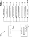
- FIG. 4 is a block diagram illustrating a hardware configuration of a main part of the printer 100.
- the printer 100 in addition to the configuration described above, further includes a registration sensor 21, a first paper sensor 22, a second paper sensor 23, and belt sensors 24 and 25.
- the registration sensor 21 detects the paper P conveyed from the paper feed cassette 2 by the paper feeding device 3 and sent to the registration roller pair 13.
- the control unit 110 is able to control the rotation start timing of the registration roller pair 13 based on the detection result of the registration sensor 21.
- the control unit 110 is able to control the supply timing of paper P after the skew (inclination) correction by the registration roller pair 13 to the first conveyor belt 8 based on the detection result of the registration sensor 21.
- the first paper sensor 22 is a line sensor that detects the position in the width direction of the paper P sent from the registration roller pair 13 to the first conveyor belt 8. Based on the detection result of the first paper sensor 22, the control unit 110 is able to record an image on the paper P by causing ink to be ejected from the ink ejection openings 18 of the ink ejection ports 18 of the recording heads 17a to 17c of the line heads 11Y to 11K that correspond to the width of the paper P.
- the second paper sensor 23 is a sensor for detecting the position in the conveying direction of the paper P conveyed by the first conveyor belt 8.
- the second paper sensor 23 is located upstream in the paper conveying direction of the recording unit 9 and downstream of the first paper sensor 22. Based on the detection result of the second paper sensor 23, the control unit 110 is able to control the ink ejection timing for the paper P reaching the position facing the line heads 11Y to 11K (recording heads 17a to 17c) by the first conveyor belt 8.
- Belt sensors 24 and 25 detect the positions of a plurality of opening portion groups 82 (see FIG. 8 ), which will be described later, provided on the first conveyor belt 8.
- the belt sensors 24 and 25 are detection sensors that detect the passage of at least one of the opening groups 82 due to the running of the first conveyor belt 8.
- the belt sensor 24 is located on the downstream side of the recording unit 9 in the paper conveying direction (the running direction of the first conveyor belt 8).
- the belt sensor 25 is located at position between the follower roller 6b and the other roller 7 where the first conveyor belt 8 is stretched around the follower roller 6b and the other roller 7.
- the follower roller 6b is located upstream of the recording unit 9 in the running direction of the first conveyor belt 8.
- the belt sensor 24 also has the same function as the second paper sensor 23.
- the control unit 110 is able to control the registration roller pair 13 so as to supply paper P to the first conveyor belt 8 at a specific timing based on the detection result of the belt sensor 24 or 25.
- the positions of the paper are detected by a plurality of sensors (second paper sensor 23, belt sensor 24), and the positions of the opening portion groups 82 of the first conveyor belt 8 are detected by a plurality of sensors (belt sensors 24 and 25), and as a result, it is possible to correct error in the detected positions and detect an abnormality.
- the first paper sensor 22, the second paper sensor 23, and the belt sensors 24 and 25 described above may be configured by a transmissive or reflective optical sensor or a CIS sensor (contact image sensor). Moreover, marks corresponding to the position of the opening portion groups 82 are formed at the end portion in the width direction of the first conveyor belt 8, and the belt sensors 24 and 25 detect the marks, whereby the positions of the opening portion groups 82 may be detected.
- the printer 100 may be configured to include a meandering detection sensor that detects the meandering of the first conveyor belt 8 and be configured to correct the meandering of the first conveyor belt 8 based on the detection result.
- the printer 100 further includes an operation panel 27, a storage unit 28, and a communication unit 29.
- the operation panel 27 is an operation unit for receiving various setting input from the user. For example, the user may operate the operation panel 27 to input information about the size of the paper P set in the paper feed cassette 2, or in other words, the size of the paper P conveyed by the first conveyor belt 8.
- the storage unit 28 is a memory that stores an operation program of the control unit 110 and also stores various types of information, and includes a ROM (Read Only Memory), a RAM (Random Access Memory), a non-volatile memory, and the like. Information set by the operation panel 27 (for example, information about the size of the paper P) is stored in the storage unit 28.
- the communication unit 29 is a communication interface (for example, a personal computer (PC)) for transmitting and receiving information to and from the outside. For example, when the user operates the PC and transmits a print command together with image data to the printer 100, the image data and the print command are inputted to the printer 100 via the communication unit 29. In the printer 100, an image may be recorded on the paper P by the control unit 110 controlling the recording heads 17a to 17c to eject ink based on the image data.
- PC personal computer
- the printer 100 has ink receiving units 31Y, 31M, 31C and 31K on the inner peripheral surface side of the first conveyor belt 8.
- the ink receiving units 31Y to 31K receive and collect the ink that has been ejected from the recording heads 17a to 17c and passed through the opening portions 80 of an opening portion groups 82 of the first conveyor belt 8 described later (see FIG. 8 ). Therefore, the ink receiving units 31Y to 31K are provided at positions facing the recording heads 17a to 17c of the line heads 11Y to 11K via the first conveyor belt 8.
- the ink collected by the ink receiving units 31Y to 31K is sent to, for example, a waste ink tank and disposed of, however, may also be reused without being disposed of.
- flushing is the ejection of ink at a timing different from the timing that contributes to image formation (image recording) on the paper P, and is for the purpose of reducing or preventing clogging of the ink ejection ports 18 due to ink drying.
- the execution of flushing in the recording heads 17a to 17c is controlled by the control unit 110.
- the second conveying unit 12 described above is configured to include a second conveyor belt 12a and a dryer 12b.
- the second conveyor belt 12a is stretched around two drive rollers 12c and a follower roller 12d.
- the paper P that is conveyed by the first conveying unit 5 and on which an image has been recorded by ink ejected by the recording unit 9 is conveyed by the second conveyor belt 12a and dried by the dryer 12b while being conveyed to the decurler unit 14 described above.
- a negative pressure suction method is adopted as a method for conveying the paper P in the first conveying unit 5.
- the negative pressure suction method is a method in which the paper P is sucked onto the first conveyor belt 8 by negative pressure suction and conveyed.
- the ink receiving units 31Y to 31K are provided at positions facing the recording heads 17a to 17c of the line heads 11Y to 11K via the first conveyor belt 8.
- the suction force of the area where the ink receiving units 31Y to 31K are provided is strong, the ink ejected from the recording heads 17a to 17c at the time of flushing vigorously passes through the opening portions 80 of the first conveyor belt 8. Then, the ink may collide with the liquid surface of ink already collected in the ink receiving unit 31Y to 31K, scattering ink into the surroundings and causing a mist to occur.
- the scattered ink adheres to the inner peripheral surface of the first conveyor belt 8 and stains the inner peripheral surface.
- the surface of the rollers around which the first conveyor belt 8 is stretched may be stained, and uneven transportation of the first conveyor belt 8 (for example, meandering or slipping) may occur.
- the suction force of the areas where the ink receiving units 31Y to 31K are provided, or in other words, the areas facing the line heads 11Y to 11K via the first conveyor belt 8 is made to be weaker than the upstream and downstream areas in the paper conveying direction. This reduces the above-mentioned inconvenience caused by the mist. More specifically, with the following configuration, areas with different suction forces are generated.
- FIG. 6 is an explanatory diagram schematically illustrating a configuration example of the first conveying unit 5.
- First suction chambers 51a to 51e and second suction chambers 52a to 52d are provided on the inner peripheral surface side of the first conveyor belt 8 of the first conveying unit 5.
- the first suction chambers 51a to 51e and the second suction chambers 52a to 52d are formed in an elongated shape in the belt width direction of the first conveyor belt 8.
- the first suction chambers 51a to 51e and the second suction chambers 52a to 52d are open on the side facing the first conveyor belt 8.
- the first suction chambers 51a to 51e are provided in this order from the downstream side to the upstream side in the paper conveying direction (direction A).
- the second suction chamber 52a is provided between the first suction chamber 51a and the first suction chamber 51b at a position facing the line head 11Y via the first conveyor belt 8.
- the second suction chamber 52b is provided between the first suction chamber 51b and the first suction chamber 51c at a position facing the line head 11M via the first conveyor belt 8.
- the second suction chamber 52c is provided between the first suction chamber 51c and the first suction chamber 51d at a position facing the line head 11C via the first conveyor belt 8.
- the second suction chamber 52d is provided between the first suction chamber 51d and the first suction chamber 51e at a position facing the line head 11K via the first conveyor belt 8.
- the ink receiving units 31Y to 31K described above are arranged in the second suction chambers 52a to 52d, respectively.
- the inner portions of the first suction chambers 51a to 51e and the second suction chambers 52a to 52d are sucked by suction members 53.
- the suction member 53 sucks the paper P onto the first conveyor belt 8 by negative pressure suction.
- This kind of a suction member 53 is composed of, for example, a fan or a compressor.
- the inner portions of the first suction chamber 51a and the second suction chamber 52a are sucked by a common suction member 53.
- the inner portions of the first suction chamber 51b and the second suction chamber 52b are sucked by a common suction member 53.
- first suction chamber 51c and the second suction chamber 52c are sucked by a common suction member 53
- the inner portions of the first suction chamber 51d and the second suction chamber 52d are sucked by a common suction member 53.
- the first suction chamber 51e is sucked alone by a suction member 53.
- a filter 54 is arranged in each of the first suction chambers 51a to 51e, and a filter 55 is arranged in each of the second suction chambers 52a to 52d. Therefore, when each suction member 53 is driven, the inside of the first suction chambers 51a to 51e is sucked through the filter 54, and the inside of the second suction chambers 52a to 52d is sucked through the filter 55. As a result, the inner portions of the first suction chambers 51a to 51e and the second suction chambers 52a to 52d have a negative pressure, and air is sucked via the suction holes 8a that will be described later (see FIG. 8 ) or the opening portion groups 82 provided on the first conveyor belt 8, and the paper P is conveyed while being sucked to the first conveyor belt 8.
- the filter 54 is configured of a coarser mesh than the filter 55. Therefore, the resistance to the air passing through the filter 54 is lower than the resistance of the air passing through the filter 55. Therefore, in a case where each suction member 53 is driven by the same driving force, the inner portions of the first suction chambers 51a to 51e are sucked with a relatively strong suction force, and the inner portions of the second suction chambers 52a to 52d are sucked with a relatively weak suction force.
- the speed at which the ink ejected from the recording heads 17a to 17c during flushing passes through the opening portions 80 of the first conveyor belt 8 is suppressed, and scattering of ink (mist) due to collision with the liquid surface of ink accumulated in the ink receiving units 31Y to 31K may be reduced. This makes it possible to reduce the above-mentioned inconvenience caused by the mist.
- FIG. 7 is an explanatory diagram schematically illustrating another configuration example of the first conveying unit 5.
- identical filters 54 are arranged in the first suction chambers 51a to 51e and the second suction chambers 52a to 52d illustrated in FIG. 6 , and each of the first suction chambers 51a to 51e and the second suction chambers 52a to 52d is configured to be sucked by a different suction member 53.
- the driving force of each suction member 53 is controlled by the control unit 110, for example.
- the first suction chambers 51a to 51e and the second suction chambers 52a to 52d are strongly sucked to convey the paper P, and at the time of flushing, only the second suction chambers 52a to 52d are weakly sucked, making it possible to reduce mist. This makes it possible to reduce the above-mentioned inconvenience caused by the mist.
- the diameters (flow passage cross-sectional areas) of the pipes that are the flow passages of the air sucked from the first suction chambers 51a to 51e and the second suction chambers 52a to 52d are made different. In doing so, the suction force may be made different between the first suction chambers 51a to 51e and the second suction chambers 52a to 52d.
- FIG. 8 is a plan view illustrating a configuration example of the first conveyor belt 8.
- paper P is conveyed by the negative pressure suction method.
- the first conveyor belt 8 is provided with innumerable suction holes 8a through which suction air generated by negative pressure suction of the suction member 53 passes.
- the first conveyor belt 8 is also provided with opening portion groups 82.
- the opening portion groups 82 are sets of opening portions 80 through which ink ejected from each nozzle (ink ejection ports 18) of the recording heads 17a to 17c passes during flushing.
- the opening area of each of the opening portions 80 is larger than the opening area of each of the above-mentioned suction holes 8a.
- the first conveyor belt 8 has a plurality of opening portion groups 82 in one cycle in the conveying direction (direction A) of the paper P, and in the present embodiment there is six. Note that when distinguishing the opening portion groups 82 from each other, the six opening portion groups 82 are referred to as opening portion groups 82A to 82F from the downstream side in the A direction.
- suction holes 8a are located between an opening portion group 82 and opening portion group 82 that are adjacent to each other in the A direction. In other words, in the first conveyor belt 8, the suction holes 8a are not formed in a region that overlaps an opening portion group 82.
- the opening portion groups 82 are irregularly positioned in the A direction in one cycle of the first conveyor belt 8.
- the interval between an opening portion group 82 and the adjacent opening group 82 is not constant but changes (there are at least two types of the above-mentioned intervals).
- the maximum interval between two adjacent opening portion groups 82 in the A direction (for example, the distance between the opening portion group 82A and the opening portion group 82B in FIG. 8 ) is longer than the length in the A direction of the paper P when the minimum printable size (for example, A4 size horizontal placement)) paper P is placed on the first conveyor belt 8.
- the opening portion groups 82 have opening portion rows 81.
- the opening portion rows 81 are configured by arranging a plurality of opening portions 80 in the belt width direction (paper width direction, BB' direction) orthogonal to the A direction.
- One opening portion group 82 has a plurality of opening portion rows 81 in the A direction, and in the present embodiment, has two opening portion rows 81. Note that when distinguishing the two opening portion rows 81 from each other, one is opening portion row 81a and the other is opening portion row 81b.
- the opening portions 80 of any one of the opening portion rows 81 are positioned offset in the BB' direction with respect to the opening portions 80 of the other opening row 81 (for example, the opening row 81b). Furthermore, the opening portions 80 are positioned so as to overlap a part of the opening portions 80 of the other opening portion row 81 (for example, the opening row 81b) when viewed in the A direction. In addition, in each opening portion row 81, the plurality of opening portions 80 are located at equal intervals in the BB' direction.
- the width of the opening portion group 82 in the BB' direction is larger than the width of the recording heads 17a to 17c in the BB' direction. Therefore, the opening portion groups 82 cover all the ink ejection areas of the recording heads 17a to 17c in the BB' direction, and the ink ejected from all the ink ejection ports 18 of the recording heads 17a to 17c during flushing passes through the opening potions 80 of one of the opening portion groups 82.
- the control unit 110 records an image on paper P by driving the recording heads 17a to 17c based on image data transmitted from the outside (for example, a PC) while paper P is conveyed using the first conveyor belt 8 described above. At this time, by causing the recording heads 17a to 17c to perform flushing (inter-paper flushing) between the conveyed paper P and paper P, clogging of the ink ejection ports 18 is reduced or prevented.
- control unit 110 sets the pattern (combination) in the A direction of the plurality of opening portion groups 82 used during flushing according to the size of the paper P to be used in one cycle of the first conveyor belt 8.
- size of the paper P to be used may be recognized by the control unit 110 based on information stored in the storage unit 28 (size information about the paper P inputted using the operation panel 27).
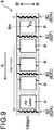
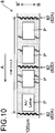
- FIGS. 9 to 12 each illustrates an example of the above patterns for each kind of paper P.
- the control unit 110 selects the pattern of the opening portion groups 82 illustrated in FIG. 9 .
- the control unit 110 selects the opening portion groups 82A, 82C, 82F from among the six opening portion groups 82 illustrated in FIG. 8 as the opening portion groups 82 to be used during flushing.
- the control unit 110 as illustrated in FIG.
- the control unit 110 selects the opening portion groups 82A, 82D, from among the six opening portion groups 82 as the opening portion groups 82 to be used for flushing.
- the control unit 110 selects the opening portion groups 82A, 82B, 82E from among the six opening groups 82 as the opening portion groups 82 to be used during flushing.
- the control unit 110 selects the opening portion groups 82A, 82D from among the six opening groups 82 as the opening portion groups 82 to be used during flushing. Note that in each of the figures, the opening portions 80 of the opening portion groups 82 belonging to the above patterns are illustrated in black for convenience.
- the control unit 110 by the running of the first conveyor belt 8, causes the recording heads 17a to 17c to execute flushing at the timing when the opening portion groups 82 positioned in the determined pattern face the recording heads 17a to 17c.
- the running speed of the first conveyor belt 8 paper conveying speed
- the spacing between the opening portion groups 82A to 82E, and the positions of the recording heads 17a to 17c with respect to the first conveyor belt 8 are all understandable. Therefore, when the belt sensor 24 or 25 detects that a reference opening portion group 82 (for example, the opening portion group 82A) has passed due to the running of the first conveyor belt 8, it is understood how many seconds after the detection time the opening groups 82A to 82E pass through the positions facing the recording heads 17a to 17c.
- control unit 110 based on the detection results of the belt sensor 24 or 25, is able to cause the recording heads 17a to 17c to execute flushing at timing when the opening portion groups 82 positioned in the determined pattern described above face the recording heads 17a to 17c.
- control unit 110 controls flushing by the recording heads 17a to 17c so that the ink passes through the same opening portion group 82 in each cycle of the first conveyor belt 8 for each class determined according to the size of the paper P.
- a case (first class) where the size of the paper P used is A4 size (horizontal placement) or letter size (horizontal placement) will be described.
- the control unit 110 controls flushing by the recording heads 17a to 17c so that ink passes trough the same opening portion groups 82A, 82C, 82F illustrated in FIG. 9 in each cycle of the first conveyor belt 8.
- a case (second class) where the size of the paper P used is A4 size (vertical placement) or letter size (vertical placement) will be described.
- the control unit 110 controls flushing by the recording heads 17a to 17c so that ink passes trough the same opening portion groups 82A, 82D illustrated in FIG. 10 in each cycle of the first conveyor belt 8.
- a case (third class) where the size of the paper P used is A3 size, B4 size or legal size (each vertically placed) will be described.
- the control unit 110 controls flushing by the recording heads 17a to 17c so that ink passes trough the same opening portion groups 82A, 82B, 82E illustrated in FIG. 11 in each cycle of the first conveyor belt 8.
- a case (fourth class) where the size of paper P used is 13 inches ⁇ 19.2 inches will be described.
- the control unit 110 controls flushing by the recording heads 17a to 17c so that ink passes trough the same opening portion groups 82A, 82D illustrated in FIG. 12 in each cycle of the first conveyor belt 8.
- control unit 110 controls the supply of the paper P to the first conveyor belt 8 so as to be shifted in the A direction from the opening portion groups 82 positioned in the determined pattern.
- control unit 110 causes the registration roller pair 13 as a recording medium supply unit to supply the paper P between the plurality of opening portion groups 82 arranged in the A direction in the pattern described above on the first conveyor belt 8.
- the control unit 110 controls the registration roller pair 13 to supply the paper P to the first conveyor belt 8 at a specific supply timing so that on the first conveyor belt 8, two sheets of paper P are arranged between the opening portion group 82A and the opening portion group 82C, two sheets of paper P are arranged between the opening portion group 82C and the opening portion group 82F, one sheet of paper P is arranged between the opening group 82F and the opening group 82A.
- control unit 110 controls the registration roller pair 13 to supply paper P to the first conveyor belt 8 so that on the first conveyor belt 8 each sheet of paper P is arranged at a position separated from the opening portion groups 82A, 82C, 82F positioned in the above pattern by a specific distance or more in the A direction (including both upstream and downstream directions).
- the specific distance above is set to 10 mm as an example here.
- the supply timing of the paper P by the registration roller pair 13 can be determined by the control unit 110 based on the detection result of the belt sensor 24 or 25.
- the belt sensor 24 or 25 detects that a reference opening portion group 82 (for example, the opening portion group 82A) has passed by due to the running of the first conveyor belt 8.
- the control unit 110 is able to determine how many seconds after the detection time the paper P can be arranged at each position illustrated in FIG. 9 by supplying the paper P to the first conveyor belt 8 by the registration roller pair 13. Therefore, the control unit 110 determines the supply timing of the paper P based on the detection result of the belt sensor 24 or 25, and controls the registration roller pair 13 so that the paper P is supplied at the determined supply timing.
- the paper P can be arranged on the first conveyor belt 8 at the respective positions illustrated in FIG. 9 at approximately equal intervals.
- five sheets of paper P can be conveyed in one cycle of the first conveyor belt 8, and 150 ipm (images per minute) can be achieved as the number of printed sheets of paper P per minute (productivity).
- the control unit 110 controls the registration roller pair 13 based on the detection result of the belt sensor 24 or 25, so that the center Po of the paper P in the A direction is located at an intermediate position 8m between the opening portion group 82F and the opening portion group 82A. Then, the control unit 110 causes paper P to be supplied from the registration roller pair 13 to the first conveyor belt 8.
- the control unit 110 controls the registration roller pair 13 so that two sheets of paper P are arranged on the first conveyor belt 8 between the opening portion group 82A and the opening portion group 82D, and so that two sheets of paper P are arranged between the opening portion group 82D and the opening portion group 82A. Then, the control unit 110 causes the paper P to be supplied to the first conveyor belt 8 at a specific supply timing. In the example of FIG. 10 , four sheets of paper P can be conveyed in one cycle of the first conveyor belt 8, and a productivity of 120 ipm can be achieved.
- the control unit 110 controls the registration roller pair 13 to supply the paper P to the first conveyor belt 8 at a specific supply timing so that on the first conveyor belt 8, one sheet of paper P is arranged between the opening portion group 82A and the opening portion group 82B, one sheet of paper P is arranged between the opening portion group 82B and the opening portion group 82E, and one sheet of paper P is arranged between the opening group 82E and the opening group 82A.
- the control unit 110 controls the registration roller pair 13 to supply the paper P to the first conveyor belt 8 at a specific supply timing so that on the first conveyor belt 8, one sheet of paper P is arranged between the opening portion group 82A and the opening portion group 82B, one sheet of paper P is arranged between the opening portion group 82B and the opening portion group 82E, and one sheet of paper P is arranged between the opening group 82E and the opening group 82A.
- control unit 110 causes the paper P to be supplied to the first conveyor belt 8 by controlling the registration roller pair 13 based on the detection result of the belt sensor 24 or 25 so that the center of one sheet of paper P in the A direction is positioned at an intermediate position between two adjacent opening portion groups 82 included in the determined pattern.
- the control unit 110 controls the registration roller pair 13 so that one sheet of paper P is arranged on the first conveyor belt 8 between the opening portion group 82A and the opening portion group 82D, and so that one sheet of paper P is arranged between the opening portion group 82D and the opening portion group 82A. Then, the control unit 110 causes the paper P to be supplied to the first conveyor belt 8 at a specific supply timing. In the example of FIG. 12 , two sheets of paper P can be conveyed in one cycle of the first conveyor belt 8, and a productivity of 60 ipm can be achieved.
- control unit 110 determines the pattern (combination) in the A direction of the plurality of opening portion groups 82 used during flushing according to the size of the paper P used.
- the control unit 110 determines the pattern (combination) in the A direction of the plurality of opening portion groups 82 used during flushing according to the size of the paper P used.
- the control unit 110 causes the recording head 17 to execute flushing at a timing when the opening portion group 82 positioned in an above-described pattern faces the recording heads 17a to 17c due to running of the first conveyor belt 8. Accordingly, flushing may be reliably performed a plurality of times during one cycle of the first conveyor belt 8 and insufficient flushing may be eliminated.
- the storage unit 28 stores the information about the size of the paper P that is inputted using the operation panel 27 in advance, or in other words, the information about the size of the paper P conveyed by the first conveyor belt 8. Then, the control unit 110 recognizes the size of the paper P to be used based on the information stored in the storage unit 28, and determines the pattern of the opening portion groups 82 according to the recognized size.
- the printer 100 may include a sensor that detects the size of the paper P to be used, and the control unit 110 may determine the pattern of the opening portion groups 82 according to the size detected by the sensor; and in this case, a dedicated sensor for detecting the size of the paper P is required.
- control unit 110 recognizes the size of the paper P based on the information stored in the storage unit 28 and determines the pattern, so the effect of this embodiment can be obtained by determining the pattern without separately providing a dedicated sensor for detecting the size of the paper P.
- control unit 110 causes the paper P to be supplied from the registration roller pair 13 between the plurality of opening portion groups 82 arranged in the above-described pattern on the first conveyor belt 8.
- the paper P is not conveyed overlapping the dirty opening portions 80. In this way, it is possible to reduce situations in which the paper P becomes stained due to the ink staining of the opening portions 80.
- the paper P is positioned away from the opening portion groups 82 in the A direction by a specific distance (for example, 10 mm) or more.
- a specific distance for example 10 mm
- One of the reasons for this may be for example, the effect of negative pressure suction of the paper P. Then, even in a case where the ink collides with the surroundings of the opening portions 80 of the opening portion groups 82 and is scattered around, or in other words, even in a case where splashing occurs, the scattered ink does not easily reach the paper P.
- the specific distance may be appropriately set according to the viscosity of the ink, the suction force on the paper P (the driving force of the suction members 53 described above), the running speed of the first conveyor belt 8 (conveying speed of the paper P), and the like. In other words, the specific distance is not limited to the 10 mm as described above.
- the control unit 110 determines the timing for supplying paper P to positions between the plurality of opening portion groups 82 on the first conveyor belt 8 (positions apart from the opening portion groups 82 by a specific distance or more in the A direction). Then, the control unit 110 causes the paper P to be supplied from the registration roller pair 13 to the first conveyor belt 8 at the determined timing. As a result, the registration roller pair 13 is able to reliably supply paper P to the above-mentioned positions between an opening portion group 82 and the opening portion group 82 of the first conveyor belt 8 to surely obtain the effect described above.
- the control unit 110 controls the flushing in the recording heads 17a to 17c based on the detection result of the belt sensor 24 or 25 so that ink passes through the same opening portion groups 82 in each cycle of the first conveyor belt 8 for each class determined according to the size of the paper P.
- the other opening portion groups 82 are not stained with ink during flushing. Therefore, regardless of the class of paper P, in each cycle of the first conveyor belt 8, such a conveyance of paper P is possible with no concern that the paper P will be stained even though conveyed so as to overlap another opening portion group 82. In other words, regardless of the class of paper P, in each cycle, it is possible convey the paper P without being stained by arranging the paper P so as to avoid the opening portion group 82 through which ink passes during flushing.
- the control unit 110 causes the paper P to be supplied from the registration roller pair 13 to the first conveyor belt 8 so that the center Po of the paper P in the A direction is positioned at an intermediate position 8m between two adjacent opening portion groups 82F and 82A of the first conveyor belt 8. At this time, the control unit 110 controls the registration roller pair 13 based on the detection result of the belt sensor 24 or 25.
- both the front end (the end portion on the downstream side in the A direction) and the rear end (the end portion on the upstream side in the A direction) of the paper P are separated by the same distance from the opening portion group 82F located on the downstream side and the opening portion group 82A located on the upstream side with respect to the paper P on the first conveyor belt 8.
- the control unit 110 causes the paper P to be supplied from the registration roller pair 13 to the first conveyor belt 8 at regular intervals.
- the supply of paper P from the registration roller pair 13 to the first conveyor belt 8 may be controlled at a constant timing, so the supply control of paper P (control of the registration roller pair 13) becomes easy.
- the first conveyor belt 8 further has suction holes 8a in addition to the opening portions 80 described above.
- the size (opening area) of the opening portions 80 is larger than the size (opening area) of the suction holes 8a.
- the suction holes 8a are large, the ink ejected from the recording heads 17a to 17c during flushing may deviate from the direction toward the opening portion 80 toward the suction holes 8a and collide with the surroundings of the opening portions 80 and cause splashing, which is a concern.
- the suction holes 8a By making the suction holes 8a relatively smaller than the opening portions 80, it is possible to further reduce the occurrence of the above-mentioned splashing and further reduce the staining of the paper P due to splashing.
- the opening portion groups 82 of the first conveyor belt 8 are irregularly positioned in the A direction in one cycle of the first conveyor belt 8.
- the effects of the present embodiment described above may be obtained by using the first conveyor belt 8 in which the minimum necessary opening portion groups 82 that can accommodate the sizes of the plurality of sheets of paper P are arranged in the A direction.
- the strength of the first conveyor belt 8 can be easily maintained.
- the A4 size (horizontal placement) and the letter size (horizontal placement) belong to the same class (first class). Then, in this class, the opening group portions 82 used for flushing are in a fixed pattern of the opening portion groups 82A, 82C, 82F.
- the A4 size (vertical placement) and the letter size (vertical placement) belong to the same class (second class). Then, in this class, the opening group portions 82 used for flushing are in a fixed pattern of the opening portion groups 82A and 82D.
- the A3 size, the B4 size, and the legal size (all vertically placed) belong to the same class (third class).
- the opening group portions 82 used for flushing are in a fixed pattern of the opening portion groups 82A, 82B and 82E. Furthermore, as illustrated in FIG. 12 , the size of 13 inches ⁇ 19.2 inches independently constitutes one class (fourth class). Then, in this class, the opening group portions 82 used for flushing are in a fixed pattern of the opening portion groups 82A and 82D.
- the pattern of the opening portion groups 82 used during flushing is a fixed pattern for each class determined according to the size of the paper P.
- the control unit 110 may perform the ejection control of ink in the recording heads 17a to 17c for each class in a pattern corresponding to the pattern of the opening portion groups 82 during flushing, and thus the ejection control is easy.
- the patterns of the opening portion groups 82 used during flushing are different from each other in FIGS. 9 and 10 , FIGS. 10 and 11 , and FIGS. 11 and 12 .
- the above patterns are the same in FIG. 10 and FIG. 12 . From this, it can be said that the patterns differ between at least two classes determined according to the size of the paper P. With such a pattern setting, flushing can be executed on any size (class) of paper P by using the opening portion groups 82 having an appropriate pattern without lowering productivity.
- the opening portion groups 82 have a plurality of opening portion rows 81 in the A direction.
- the opening portions 80 of any one of the opening portion rows 81 (for example, the opening portions 81a) is shifted from the opening portions 80 of the other opening row 81 (for example, the opening portion row 81b) in the belt width direction, and is located so as to overlap with part of the opening portions 80 of the other opening portion row 81 when viewed in the A direction.
- the nozzles (ink ejection ports 18) at any position in the width direction of the recording heads 17a to 17c eject ink from the nozzles, and flushing can be performed by passing the ink through the opening portions 80 at any position in the belt width direction of the first conveyor belt 8. Therefore, it is possible to reduce or prevent nozzle clogging for nozzles at all positions in the width direction.
- the plurality of opening portions 80 of the opening portion rows 81 are located at equal intervals in the belt width direction.
- the first conveyor belt 8 has six opening portion groups 82 in the A direction in one cycle. In this case, for the four classes classified according to the size of the paper P, it is possible to generate a pattern in the A direction of the opening portion groups 82 without lowering the productivity.
- the first conveyor belt 8 may have seven or more opening portion groups 82 in the A direction in one cycle. In this case, it is possible to generate a pattern in the A direction of the opening portion groups 82 that does not reduce the productivity for five or more classes classified according to the size of the paper P.
- FIG. 13 is a plan view illustrating another configuration example of the first conveyor belt 8.
- the first conveyor belt 8 may have a configuration in which the opening portion groups 82 described above are located at equal intervals in the conveying direction of the first conveyor belt 8, or in other words, the A direction.
- two opening portion groups 82 adjacent to each other in the A direction are arranged at intervals shorter than the length of the paper P in the A direction when the smallest printable size of the paper P is placed on the first conveyor belt 8.
- the opening portions 80 that constitute the opening portion groups 82 also serve as suction holes 8a in the configuration of FIG. 8 .
- the opening portion groups 82 have a plurality of opening portion rows 81, and one opening portion row 81 has a plurality of opening portions 80 arranged at equal intervals in the BB' direction, or in other words, is the same as the first conveyor belt 8 described in FIG. 8 and the like.
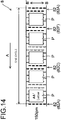
- the control unit 110 determines a pattern of the plurality of opening portion groups 82 in the A direction that will be used according to the size of the paper P to be used. For example, in a case where the paper P to be used is A4 size (horizontal placement) or letter size (horizontal placement), the control unit 110 selects the pattern of the opening portion groups 82 illustrated in FIG. 14 . In a case where the paper P to be used is A4 size (vertical placement) or letter size (vertical placement), the control unit 110 selects the pattern of the opening portion groups 82 illustrated in FIG. 15 .
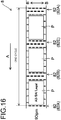
- the control unit 110 selects the pattern of the opening portion groups 82 illustrated in FIG. 16 .
- the control unit 110 selects the pattern of the opening portion groups 82 illustrated in FIG. 17 . Note that, in FIGS. 14 to 17 , for convenience, the opening portion groups 82 in positions corresponding to the opening portion groups 82A to 82F in FIG. 8 are illustrated as the opening portion groups 82A to 82F.
- control unit 110 by the running of the first conveyor belt 8, causes the recording heads 17a to 17c to execute flushing at the timing when the opening portion groups 82 positioned in the determined pattern face the recording heads 17a to 17c.
- control unit 110 causes the registration roller pair 13 to supply the paper P to the position illustrated in FIGS. 14 to 17 on the first conveyor belt 8 (between the plurality of opening portion groups 82 arranged in the direction A in the above pattern). At this time, the control unit 110 controls the registration roller pair 13 so that each sheet of paper P is arranged on the first conveyor belt 8 at a position separated from the opening portion groups 82 positioned in the above pattern by a specific distance or more in the direction A (including both the upstream side and the downstream side). Then, the control unit 110 causes the paper P to be supplied to the first conveyor belt 8.
- the control unit 110 performs the same control (flushing control, paper P supply control) as that when the first conveyor belt 8 illustrated in FIG. 8 is used.
- the same control flush control, paper P supply control
- a configuration in which the opening portion groups 82 are located at equal intervals in the A direction of the first conveyor belt 8 can be easily achieved by forming holes in the first conveyor belt 8 at constant intervals in the A direction. Therefore, manufacturing the first conveyor belt 8 is simplified, and the manufacturing cost thereof can be reduced.
- the opening area of the opening portions 80 is equal to the opening area of the suction holes 8a and only one type of hole size needs to be formed in the first conveyor belt 8. From this aspect as well, manufacturing of the first conveyor belt 8 is easier than in the case of the configuration of FIG. 8 in which two different types of hole sizes are formed.
- the first conveyor belt 8 may have the configuration illustrated in FIG. 8 or the configuration illustrated in FIG. 13 . Therefore, in summarizing the configurations of FIGS. 8 and 13 , it can be said that in the first conveyor belt 8, the size of the opening portions 80 may be equal to or larger than the size of the suction holes 8a.
- innumerable opening portions 80 for flushing are formed over the entire surface of the belt. Therefore, the paper P can be packed and conveyed in the A direction on the first conveyor belt 8, and by performing flushing using the opening portions 80 at a position not overlapped by the paper P, it is possible to significantly improve productivity
- the opening portions 80 which become stained due to the passage of ink during flushing, and the paper P to be conveyed are likely to overlap with each other in each cycle of the first conveyor belt 8, making it easier for the paper P to become stained.
- the pattern of the opening portion groups 82 used at the time of flushing is determined according to the size of the paper P, and flushing is performed using the opening portion groups 82 positioned in the determined pattern.
- the paper P can be arranged and conveyed at positions shifted from the opening portion groups 82 used for flushing. Accordingly, it is possible to reduce stains on the paper P when the paper P is conveyed and printed over a plurality of cycles while at the same time maintain productivity.
- the flushing control and the paper P supply control described in the present embodiment are effective even when the first conveyor belt 8 having the configuration of FIG. 13 is used.
- the pattern of the opening portion groups 82 used during flushing may be a different pattern than the pattern used in a case where the first conveyor belt 8 illustrated in FIG. 8 is used.
- the flushing may be performed on the opening portion groups located between the paper P and the paper P conveyed at the positions illustrated in FIGS. 14 to 17 .
- the paper P is sucked to the first conveyor belt 8 by negative pressure and conveyed
- the first conveyor belt 8 may be electrically charged and the paper P may be electrostatically sucked to the first conveyor belt 8 and conveyed (electrostatic attraction method).
- electrostatic attraction method electrostatic attraction method
- the number of times of flushing in the same recording head is once in one cycle of the conveyor belt regardless of the size of the recording medium used, and the frequency of flushing is low. Therefore, regardless of the size of the recording medium used, insufficient flushing is likely to occur, and a reduction in nozzle clogging due to flushing is insufficient.
- the reduction in the conveying speed reduces the number of recording media conveyed in one cycle of the conveyor belt, so the number of printed recording medium, or in other words, the productivity is reduced.
- the productivity of the recording medium is not studied at all.
- the recording medium is placed on the conveyor belt and conveyed, for example, by negative pressure suction or electrostatic attraction.
- the suction force or the electrostatic force due to the influence of the suction force or the electrostatic force, the ink ejected from the recording head at the time of flushing may deviate in the conveying direction from the path toward the opening portions of the conveyor belt and progress.
- the ink will collide with the surroundings of the opening portions and be scattered to the surroundings, or in other words, splashing may occur, and the scattered ink may adhere to the recording medium and stain the recording medium. Therefore, it is also necessary to reduce the staining of the recording medium due to splashing of the ink.
- the inkjet recording apparatus regardless of the size of the recording medium used, it is possible to reduce the clogging of the nozzles due to insufficient flushing while avoiding a decrease in productivity of the recording medium. Together with this, it is possible to reduce situations in which the recording medium is stained due to staining of the opening portions with the ink ejected during flushing. It is also possible to reduce situations in which the recording medium is stained due to the direct adhering of ink.
- the technique according to the present disclosure can be used for an inkjet recording apparatus that records an image by ejecting ink onto a recording medium.
Landscapes
- Ink Jet (AREA)
Abstract
Description
- The present disclosure relates to an inkjet recording apparatus that records an image by ejecting ink onto a recording medium.
- Conventionally, in an inkjet recording apparatus such as an inkjet printer and the like, flushing (idle ejection) for ejecting ink from the nozzles is regularly performed in order to reduce or prevent clogging of the nozzles due to drying of the ink. For example, in an inkjet recording apparatus of a typical technique, an opening portion is provided in a conveyor belt, and a recording medium is placed on the conveyor belt so as not to cover the opening portion and conveyed. Then, when the opening portion reaches a position facing the recording head due to the running of the conveyor belt ink is ejected from the nozzles of the recording head to perform flushing. An ink absorber such as a sponge or the like is arranged on the side opposite to the recording head (inner peripheral surface side) with respect to the conveyor belt, and ink that is ejected from the recording head and passed through the opening portion during flushing is absorbed by the ink absorber.
- Moreover, for example, in an inkjet recording apparatus of a typical technique, a plurality of opening portions are provided in the conveyor belt in the conveying direction of the recording medium, and in a case where the size of the recording medium is large, the conveying speed of the recording medium is slowed to perform flushing. By decreasing the conveying speed of the recording medium, the number of rows in the conveying direction of the opening portions located between the recording media on the conveyor belt increases, so ejection defects may be reduced by increasing the ink ejection amount required for flushing. Furthermore, in a typical technique, the position of the opening portions is recognized based on the detection result of a mark provided on the conveyor belt, and the ejection of ink in flushing is controlled to take into account deformation such as elongation of the conveyor belt and the like, whereby ink is more accurately passed through the opening portions.
- In order to achieve the object described above, an inkjet recording apparatus according to one aspect of the present disclosure includes a recording head and an endless conveyor belt. The recording head has a plurality of nozzles for ejecting ink. The endless conveyor belt conveys a recording medium to a position facing the recording head. In addition to this, the inkjet recording apparatus includes a recording medium supply unit and a control unit. The recording medium supply unit supplies the recording medium to the conveyor belt. The control unit, together with causing the recording head to execute flushing for ejecting the ink at a timing different from timing that contributes to image formation on the recording medium, controls supply of the recording medium to the conveyor belt by the recording medium supply unit. The conveyor belt has a plurality of opening portion groups in which opening portions are arranged in a belt width direction perpendicular to the conveying direction of the recording medium. The opening portions allow ink ejected from each of the nozzles of the recording head to pass during the flushing. The control unit determines the pattern of the plurality of the opening portion groups used for the flushing in one cycle of the conveyor belt according to the size of the recording medium. In addition, the control unit causes the recording medium to be supplied from the recording medium supply unit between the plurality of opening groups arranged in the conveying direction in the pattern on the conveyor belt and at positions separated from the opening portion groups by a specific distance or more.
-
-
FIG. 1 is an explanatory diagram illustrating a schematic configuration of a printer as an inkjet recording apparatus according to an embodiment of the present disclosure. -
FIG. 2 is a plan view of a recording unit included in the printer. -
FIG. 3 is an explanatory diagram schematically illustrating the configuration around the paper conveying path from the paper feed cassette of the printer to a second conveying unit via a first conveying unit. -
FIG. 4 is a block diagram illustrating a hardware configuration of a main part of the printer. -
FIG. 5 is explanatory diagram schematically illustrating an area in the first conveying unit where suction force differs. -
FIG. 6 is an explanatory diagram schematically illustrating a configuration example of the first conveying unit. -
FIG. 7 is an explanatory diagram schematically illustrating another configuration example of the first conveying unit. -
FIG. 8 is a plan view illustrating a configuration example of a first conveyor belt of the first conveying unit. -
FIG. 9 is an explanatory diagram schematically illustrating an example of a pattern of a group of opening portions for flushing when the first conveyor belt ofFIG. 8 is used, and illustrates paper arranged on the first conveyor belt according to the pattern. -
FIG. 10 is an explanatory diagram schematically illustrating another example of the pattern and paper arranged on the first conveyor belt according to the pattern. -
FIG. 11 is an explanatory diagram schematically illustrating yet another example of the pattern and paper arranged on the first conveyor belt according to the pattern. -
FIG. 12 is an explanatory diagram schematically illustrating yet another example of the pattern and paper arranged on the first conveyor belt according to the pattern. -
FIG. 13 is a plan view illustrating another configuration example of the first conveyor belt. -
FIG. 14 is an explanatory diagram schematically showing an example of the pattern when the first conveyor belt ofFIG. 13 is used and paper arranged on the first conveyor belt according to the pattern. -
FIG. 15 is an explanatory diagram schematically illustrating another example of the pattern and paper arranged on the first conveyor belt according to the pattern. -
FIG. 16 is an explanatory diagram schematically illustrating yet another example of the pattern and paper arranged on the first conveyor belt according to the pattern. -
FIG. 17 is an explanatory diagram schematically illustrating yet another example of the pattern and paper arranged on the first conveyor belt according to the pattern. - Hereinafter, embodiments of the present disclosure will be described with reference to the drawings.
FIG. 1 is an explanatory diagram illustrating a schematic configuration of aprinter 100 as an inkjet recording apparatus according to an embodiment of the present disclosure. Theprinter 100 includes apaper feed cassette 2 that is a paper storage unit. Thepaper feed cassette 2 is arranged at the lower inner portion of the printer body 1. Paper P, which is an example of a recording medium, is housed inside thepaper feed cassette 2. - A
paper feeding device 3 is arranged on the downstream side in the paper conveying direction of thepaper feed cassette 2, tor in other words, above the right side of thepaper feed cassette 2 inFIG. 1 . By thispaper feeding device 3, paper P is directed toward the upper right of thepaper feed cassette 2 inFIG. 1 , and is separated and fed out one sheet at a time. - The
printer 100 includes a firstpaper conveying path 4a in the inner portion thereof. The firstpaper conveying path 4a is located on the upper right side, which is the paper feed direction, with respect to thepaper feed cassette 2. The paper P fed out from thepaper feed cassette 2 is conveyed vertically upward along the side surface of the printer body 1 by the firstpaper conveying path 4a. - A
registration roller pair 13 is provided at the downstream end of the firstpaper conveying path 4a in the paper conveying direction. Furthermore, afirst conveying unit 5 and therecording unit 9 are arranged immediately downstream of theregistration roller pair 13 in the paper conveying direction. The paper P fed out from thepaper feed cassette 2 reaches theregistration roller pair 13 via the firstpaper conveying path 4a. Theregistration roller pair 13 feeds the paper P toward thefirst conveying unit 5 while correcting diagonal feeding of the paper P and measuring the timing with the ink ejection operation performed by therecording unit 9. - The paper P fed to the
first conveying unit 5 is conveyed to a position facing the recording unit 9 (especiallyrecording heads 17a to 17c described later) by the first conveyor belt 8 (seeFIG. 2 ). An image is recorded on the paper P by ejecting ink from therecording unit 9 onto the paper P. At this time, the ejection of ink in therecording unit 9 is controlled by thecontrol unit 110 in the inner portion of theprinter 100. Thecontrol unit 110 includes, for example, a central processing unit (CPU). - The
second conveying unit 12 is arranged on the downstream side (left side inFIG. 1 ) of thefirst conveying unit 5 in the paper conveying direction. The paper P on which the image is recorded by therecording unit 9 is sent to thesecond conveying unit 12. The ink ejected onto the surface of the paper P is dried while passing through thesecond conveying unit 12. - A
decurler unit 14 is provided on the downstream side of thesecond conveying unit 12 in the paper conveying direction and near the left side surface of the printer body 1. The paper P whose ink has been dried by thesecond conveying unit 12 is sent to thedecurler unit 14 in order to correct curling that has occurred in the paper P. - A second
paper conveying path 4b is provided on the downstream side (upper side inFIG. 1 ) of thedecurler unit 14 in the paper conveying direction. In a case where double-sided recording is not performed, paper P that has passed through thedecurler unit 14 passes through the secondpaper conveying path 4b and is discharged to thepaper discharge tray 15 provided in the outer portion of the left side surface of theprinter 100. - A
reverse conveying path 16 for performing double-sided recording is provided in the upper portion of the printer body 1 above therecording unit 9 and the second conveyingunit 12. In a case of performing double-sided recording, the paper P that has passed through the second conveyingunit 12 and thedecurler unit 14 after recording on one surface (first surface) of the paper P is sent to thereverse conveying path 16 through the secondpaper conveying path 4b. - The conveying direction of the paper P sent to the
reverse conveying path 16 is subsequently switched for recording on the other surface (second surface) of the paper P. Then, the paper P passes through the upper portion of the printer body 1 and is sent toward the right side, and is sent again, via theregistration roller pair 13, to the first conveyingunit 5 with the second surface thereof facing upward. In the first conveyingunit 5, the paper P is conveyed to a position facing therecording unit 9, and an image is recorded on the second surface by ejecting ink from therecording unit 9. The paper P after double-sided recording is discharged to thepaper discharge tray 15 via the second conveyingunit 12, thedecurler unit 14, and the secondpaper conveying path 4b in this order. - Moreover, a
maintenance unit 19 and a cap unit 20 are arranged below the second conveyingunit 12. When executing purging, themaintenance unit 19 moves horizontally below therecording unit 9, wipes the ink extruded from the ink ejection port of the recording head, and collects the wiped ink. Note that purging refers to an operation of forcibly extruding the ink from the ink ejection port of the recording head in order to discharge thickened ink, foreign matter and air bubbles in the ink ejection port. The cap unit 20 moves horizontally below therecording unit 9 when capping the ink ejection surface of the recording head, moves further upward, and is attached to the lower surface of the recording head. -
FIG. 2 is a plan view of therecording unit 9. Therecording unit 9 includes ahead housing 10 and line heads 11Y, 11M, 11C and 11K. The line heads 11Y to 11K are held in thehead housing 10 at a height at which specific spacing (for example, 1 mm) is formed with respect to the conveying surface of an endlessfirst conveyor belt 8 that spans around a plurality of rollers including adrive roller 6a, afollower roller 6b, and anotherroller 7. - The line heads 11Y to 11K have a plurality of (here, three) recording heads 17a to 17c, respectively. The recording heads 17a to 17c are arranged in a zigzag pattern along the paper width direction (direction of arrow BB') orthogonal to the paper conveying direction (direction of arrow A). The recording heads 17a to 17c have a plurality of ink ejection ports 18 (nozzles). The
ink ejection ports 18 are arranged at equal intervals in the width direction of the recording head, or in other words, the paper width direction (direction of arrow BB'). From the line heads 11Y to 11K, ink of each color of yellow (Y), magenta (M), cyan (C), and black (K) is respectively ejected via theink ejection ports 18 of the recording heads 17a to 17c toward the paper P that is conveyed by thefirst conveyor belt 8. -
FIG. 3 schematically illustrates the configuration around the conveying path of the paper P from thepaper feed cassette 2 to the second conveyingunit 12 via the first conveyingunit 5. Moreover,FIG. 4 is a block diagram illustrating a hardware configuration of a main part of theprinter 100. Theprinter 100, in addition to the configuration described above, further includes aregistration sensor 21, afirst paper sensor 22, asecond paper sensor 23, andbelt sensors - The
registration sensor 21 detects the paper P conveyed from thepaper feed cassette 2 by thepaper feeding device 3 and sent to theregistration roller pair 13. Thecontrol unit 110 is able to control the rotation start timing of theregistration roller pair 13 based on the detection result of theregistration sensor 21. For example, thecontrol unit 110 is able to control the supply timing of paper P after the skew (inclination) correction by theregistration roller pair 13 to thefirst conveyor belt 8 based on the detection result of theregistration sensor 21. - The
first paper sensor 22 is a line sensor that detects the position in the width direction of the paper P sent from theregistration roller pair 13 to thefirst conveyor belt 8. Based on the detection result of thefirst paper sensor 22, thecontrol unit 110 is able to record an image on the paper P by causing ink to be ejected from theink ejection openings 18 of theink ejection ports 18 of the recording heads 17a to 17c of the line heads 11Y to 11K that correspond to the width of the paper P. - The
second paper sensor 23 is a sensor for detecting the position in the conveying direction of the paper P conveyed by thefirst conveyor belt 8. Thesecond paper sensor 23 is located upstream in the paper conveying direction of therecording unit 9 and downstream of thefirst paper sensor 22. Based on the detection result of thesecond paper sensor 23, thecontrol unit 110 is able to control the ink ejection timing for the paper P reaching the position facing the line heads 11Y to 11K (recording heads 17a to 17c) by thefirst conveyor belt 8. -
Belt sensors FIG. 8 ), which will be described later, provided on thefirst conveyor belt 8. In other words, thebelt sensors groups 82 due to the running of thefirst conveyor belt 8. Thebelt sensor 24 is located on the downstream side of therecording unit 9 in the paper conveying direction (the running direction of the first conveyor belt 8). Thebelt sensor 25 is located at position between thefollower roller 6b and theother roller 7 where thefirst conveyor belt 8 is stretched around thefollower roller 6b and theother roller 7. Thefollower roller 6b is located upstream of therecording unit 9 in the running direction of thefirst conveyor belt 8. Note that thebelt sensor 24 also has the same function as thesecond paper sensor 23. Thecontrol unit 110 is able to control theregistration roller pair 13 so as to supply paper P to thefirst conveyor belt 8 at a specific timing based on the detection result of thebelt sensor - Moreover, the positions of the paper are detected by a plurality of sensors (
second paper sensor 23, belt sensor 24), and the positions of theopening portion groups 82 of thefirst conveyor belt 8 are detected by a plurality of sensors (belt sensors 24 and 25), and as a result, it is possible to correct error in the detected positions and detect an abnormality. - The
first paper sensor 22, thesecond paper sensor 23, and thebelt sensors opening portion groups 82 are formed at the end portion in the width direction of thefirst conveyor belt 8, and thebelt sensors opening portion groups 82 may be detected. - In addition, the
printer 100 may be configured to include a meandering detection sensor that detects the meandering of thefirst conveyor belt 8 and be configured to correct the meandering of thefirst conveyor belt 8 based on the detection result. - In addition, the
printer 100 further includes an operation panel 27, astorage unit 28, and acommunication unit 29. The operation panel 27 is an operation unit for receiving various setting input from the user. For example, the user may operate the operation panel 27 to input information about the size of the paper P set in thepaper feed cassette 2, or in other words, the size of the paper P conveyed by thefirst conveyor belt 8. Thestorage unit 28 is a memory that stores an operation program of thecontrol unit 110 and also stores various types of information, and includes a ROM (Read Only Memory), a RAM (Random Access Memory), a non-volatile memory, and the like. Information set by the operation panel 27 (for example, information about the size of the paper P) is stored in thestorage unit 28. Thecommunication unit 29 is a communication interface (for example, a personal computer (PC)) for transmitting and receiving information to and from the outside. For example, when the user operates the PC and transmits a print command together with image data to theprinter 100, the image data and the print command are inputted to theprinter 100 via thecommunication unit 29. In theprinter 100, an image may be recorded on the paper P by thecontrol unit 110 controlling the recording heads 17a to 17c to eject ink based on the image data. - Moreover, as illustrated in
FIG. 3 , theprinter 100 hasink receiving units first conveyor belt 8. When the recording heads 17a to 17c are made to execute flushing, theink receiving units 31Y to 31K receive and collect the ink that has been ejected from the recording heads 17a to 17c and passed through the openingportions 80 of anopening portion groups 82 of thefirst conveyor belt 8 described later (seeFIG. 8 ). Therefore, theink receiving units 31Y to 31K are provided at positions facing the recording heads 17a to 17c of the line heads 11Y to 11K via thefirst conveyor belt 8. Note that the ink collected by theink receiving units 31Y to 31K is sent to, for example, a waste ink tank and disposed of, however, may also be reused without being disposed of. - Here, flushing is the ejection of ink at a timing different from the timing that contributes to image formation (image recording) on the paper P, and is for the purpose of reducing or preventing clogging of the
ink ejection ports 18 due to ink drying. The execution of flushing in the recording heads 17a to 17c is controlled by thecontrol unit 110. - The second conveying
unit 12 described above is configured to include asecond conveyor belt 12a and adryer 12b. Thesecond conveyor belt 12a is stretched around twodrive rollers 12c and afollower roller 12d. The paper P that is conveyed by the first conveyingunit 5 and on which an image has been recorded by ink ejected by therecording unit 9 is conveyed by thesecond conveyor belt 12a and dried by thedryer 12b while being conveyed to thedecurler unit 14 described above. - In the present embodiment, a negative pressure suction method is adopted as a method for conveying the paper P in the first conveying
unit 5. The negative pressure suction method is a method in which the paper P is sucked onto thefirst conveyor belt 8 by negative pressure suction and conveyed. - Here, as described above, the
ink receiving units 31Y to 31K are provided at positions facing the recording heads 17a to 17c of the line heads 11Y to 11K via thefirst conveyor belt 8. During negative pressure suction, in a case where the suction force of the area where theink receiving units 31Y to 31K are provided is strong, the ink ejected from the recording heads 17a to 17c at the time of flushing vigorously passes through the openingportions 80 of thefirst conveyor belt 8. Then, the ink may collide with the liquid surface of ink already collected in theink receiving unit 31Y to 31K, scattering ink into the surroundings and causing a mist to occur. In a case where a mist occurs, the scattered ink adheres to the inner peripheral surface of thefirst conveyor belt 8 and stains the inner peripheral surface. As a result, the surface of the rollers around which thefirst conveyor belt 8 is stretched may be stained, and uneven transportation of the first conveyor belt 8 (for example, meandering or slipping) may occur. - Therefore, in the present embodiment, as illustrated in
FIG. 5 , the suction force of the areas where theink receiving units 31Y to 31K are provided, or in other words, the areas facing the line heads 11Y to 11K via thefirst conveyor belt 8 is made to be weaker than the upstream and downstream areas in the paper conveying direction. This reduces the above-mentioned inconvenience caused by the mist. More specifically, with the following configuration, areas with different suction forces are generated. -
FIG. 6 is an explanatory diagram schematically illustrating a configuration example of the first conveyingunit 5.First suction chambers 51a to 51e andsecond suction chambers 52a to 52d are provided on the inner peripheral surface side of thefirst conveyor belt 8 of the first conveyingunit 5. Thefirst suction chambers 51a to 51e and thesecond suction chambers 52a to 52d are formed in an elongated shape in the belt width direction of thefirst conveyor belt 8. Thefirst suction chambers 51a to 51e and thesecond suction chambers 52a to 52d are open on the side facing thefirst conveyor belt 8. - The
first suction chambers 51a to 51e are provided in this order from the downstream side to the upstream side in the paper conveying direction (direction A). Thesecond suction chamber 52a is provided between thefirst suction chamber 51a and thefirst suction chamber 51b at a position facing theline head 11Y via thefirst conveyor belt 8. Thesecond suction chamber 52b is provided between thefirst suction chamber 51b and thefirst suction chamber 51c at a position facing theline head 11M via thefirst conveyor belt 8. Thesecond suction chamber 52c is provided between thefirst suction chamber 51c and thefirst suction chamber 51d at a position facing theline head 11C via thefirst conveyor belt 8. Thesecond suction chamber 52d is provided between thefirst suction chamber 51d and thefirst suction chamber 51e at a position facing theline head 11K via thefirst conveyor belt 8. Theink receiving units 31Y to 31K described above are arranged in thesecond suction chambers 52a to 52d, respectively. - The inner portions of the
first suction chambers 51a to 51e and thesecond suction chambers 52a to 52d are sucked bysuction members 53. Thesuction member 53 sucks the paper P onto thefirst conveyor belt 8 by negative pressure suction. This kind of asuction member 53 is composed of, for example, a fan or a compressor. In the present embodiment, the inner portions of thefirst suction chamber 51a and thesecond suction chamber 52a are sucked by acommon suction member 53. Moreover, the inner portions of thefirst suction chamber 51b and thesecond suction chamber 52b are sucked by acommon suction member 53. Similarly, the inner portions of thefirst suction chamber 51c and thesecond suction chamber 52c are sucked by acommon suction member 53, and the inner portions of thefirst suction chamber 51d and thesecond suction chamber 52d are sucked by acommon suction member 53. Thefirst suction chamber 51e is sucked alone by asuction member 53. - A
filter 54 is arranged in each of thefirst suction chambers 51a to 51e, and afilter 55 is arranged in each of thesecond suction chambers 52a to 52d. Therefore, when eachsuction member 53 is driven, the inside of thefirst suction chambers 51a to 51e is sucked through thefilter 54, and the inside of thesecond suction chambers 52a to 52d is sucked through thefilter 55. As a result, the inner portions of thefirst suction chambers 51a to 51e and thesecond suction chambers 52a to 52d have a negative pressure, and air is sucked via thesuction holes 8a that will be described later (seeFIG. 8 ) or theopening portion groups 82 provided on thefirst conveyor belt 8, and the paper P is conveyed while being sucked to thefirst conveyor belt 8. - Here, the
filter 54 is configured of a coarser mesh than thefilter 55. Therefore, the resistance to the air passing through thefilter 54 is lower than the resistance of the air passing through thefilter 55. Therefore, in a case where eachsuction member 53 is driven by the same driving force, the inner portions of thefirst suction chambers 51a to 51e are sucked with a relatively strong suction force, and the inner portions of thesecond suction chambers 52a to 52d are sucked with a relatively weak suction force. As a result, the speed at which the ink ejected from the recording heads 17a to 17c during flushing passes through the openingportions 80 of thefirst conveyor belt 8 is suppressed, and scattering of ink (mist) due to collision with the liquid surface of ink accumulated in theink receiving units 31Y to 31K may be reduced. This makes it possible to reduce the above-mentioned inconvenience caused by the mist. -
FIG. 7 is an explanatory diagram schematically illustrating another configuration example of the first conveyingunit 5. In the first conveyingunit 5 ofFIG. 7 ,identical filters 54 are arranged in thefirst suction chambers 51a to 51e and thesecond suction chambers 52a to 52d illustrated inFIG. 6 , and each of thefirst suction chambers 51a to 51e and thesecond suction chambers 52a to 52d is configured to be sucked by adifferent suction member 53. In such a configuration, by switching the driving force of eachsuction member 53 that sucks the inner portions of thesecond suction chambers 52a to 52d, the suction force of thesecond suction chambers 52a to 52d is switched between strong suction and weak suction. Note that the driving of eachsuction member 53 is controlled by thecontrol unit 110, for example. - For example, when ink is ejected onto the paper P conveyed by the first conveyor belt 8 (at the time of recording an image), all of the
suction members 53 that suck thefirst suction chambers 51a to 51e and thesecond suction chambers 52a to 52d are driven by a first driving force. On the other hand, at the time of flushing, eachsuction member 53 that sucks thefirst suction chambers 51a to 51e is driven by the first driving force, and eachsuction member 53 that sucks thesecond suction chambers 52a to 52d is driven by a second driving force that is lower than the first driving force. As a result, at the time of recording an image, thefirst suction chambers 51a to 51e and thesecond suction chambers 52a to 52d are strongly sucked to convey the paper P, and at the time of flushing, only thesecond suction chambers 52a to 52d are weakly sucked, making it possible to reduce mist. This makes it possible to reduce the above-mentioned inconvenience caused by the mist. - In addition, instead of using the
filters first suction chambers 51a to 51e and thesecond suction chambers 52a to 52d are made different. In doing so, the suction force may be made different between thefirst suction chambers 51a to 51e and thesecond suction chambers 52a to 52d. - Next, details of the
first conveyor belt 8 of the first conveyingunit 5 will be described.FIG. 8 is a plan view illustrating a configuration example of thefirst conveyor belt 8. In the present embodiment, as described above, paper P is conveyed by the negative pressure suction method. In order for this, as illustrated inFIG. 8 , thefirst conveyor belt 8 is provided withinnumerable suction holes 8a through which suction air generated by negative pressure suction of thesuction member 53 passes. - Moreover, the
first conveyor belt 8 is also provided with opening portion groups 82. Theopening portion groups 82 are sets of openingportions 80 through which ink ejected from each nozzle (ink ejection ports 18) of the recording heads 17a to 17c passes during flushing. The opening area of each of the openingportions 80 is larger than the opening area of each of the above-mentionedsuction holes 8a. Thefirst conveyor belt 8 has a plurality of openingportion groups 82 in one cycle in the conveying direction (direction A) of the paper P, and in the present embodiment there is six. Note that when distinguishing theopening portion groups 82 from each other, the sixopening portion groups 82 are referred to as openingportion groups 82A to 82F from the downstream side in the A direction. The above-mentionedsuction holes 8a are located between an openingportion group 82 andopening portion group 82 that are adjacent to each other in the A direction. In other words, in thefirst conveyor belt 8, thesuction holes 8a are not formed in a region that overlaps anopening portion group 82. - The
opening portion groups 82 are irregularly positioned in the A direction in one cycle of thefirst conveyor belt 8. In other words, in the A direction, the interval between an openingportion group 82 and theadjacent opening group 82 is not constant but changes (there are at least two types of the above-mentioned intervals). In this case, the maximum interval between two adjacentopening portion groups 82 in the A direction (for example, the distance between the openingportion group 82A and theopening portion group 82B inFIG. 8 ) is longer than the length in the A direction of the paper P when the minimum printable size (for example, A4 size horizontal placement)) paper P is placed on thefirst conveyor belt 8. - The
opening portion groups 82 have openingportion rows 81. The openingportion rows 81 are configured by arranging a plurality of openingportions 80 in the belt width direction (paper width direction, BB' direction) orthogonal to the A direction. Oneopening portion group 82 has a plurality of openingportion rows 81 in the A direction, and in the present embodiment, has two openingportion rows 81. Note that when distinguishing the twoopening portion rows 81 from each other, one is openingportion row 81a and the other is openingportion row 81b. - In one
opening group 82, the openingportions 80 of any one of the opening portion rows 81 (for example, the openingportion row 81a) are positioned offset in the BB' direction with respect to the openingportions 80 of the other opening row 81 (for example, theopening row 81b). Furthermore, the openingportions 80 are positioned so as to overlap a part of the openingportions 80 of the other opening portion row 81 (for example, theopening row 81b) when viewed in the A direction. In addition, in each openingportion row 81, the plurality of openingportions 80 are located at equal intervals in the BB' direction. - As described above, by arranging the plurality of opening
portion rows 81 in the A direction to form oneopening portion group 82, the width of theopening portion group 82 in the BB' direction is larger than the width of the recording heads 17a to 17c in the BB' direction. Therefore, theopening portion groups 82 cover all the ink ejection areas of the recording heads 17a to 17c in the BB' direction, and the ink ejected from all theink ejection ports 18 of the recording heads 17a to 17c during flushing passes through the openingpotions 80 of one of the opening portion groups 82. - In the present embodiment, the
control unit 110 records an image on paper P by driving the recording heads 17a to 17c based on image data transmitted from the outside (for example, a PC) while paper P is conveyed using thefirst conveyor belt 8 described above. At this time, by causing the recording heads 17a to 17c to perform flushing (inter-paper flushing) between the conveyed paper P and paper P, clogging of theink ejection ports 18 is reduced or prevented. - Here, in the present embodiment, the
control unit 110 sets the pattern (combination) in the A direction of the plurality of openingportion groups 82 used during flushing according to the size of the paper P to be used in one cycle of thefirst conveyor belt 8. Note that the size of the paper P to be used may be recognized by thecontrol unit 110 based on information stored in the storage unit 28 (size information about the paper P inputted using the operation panel 27). -
FIGS. 9 to 12 each illustrates an example of the above patterns for each kind of paper P. For example, in a case where the paper P to be used is A4 size (horizontal placement) or letter size (horizontal placement), thecontrol unit 110 selects the pattern of theopening portion groups 82 illustrated inFIG. 9 . In other words, thecontrol unit 110 selects theopening portion groups opening portion groups 82 illustrated inFIG. 8 as theopening portion groups 82 to be used during flushing. In a case where the paper P to be used is A4 size (vertical placement) or letter size (vertical placement), thecontrol unit 110, as illustrated inFIG. 10 , selects theopening portion groups opening portion groups 82 as theopening portion groups 82 to be used for flushing. In a case where the paper P to be used is A3 size, B4 size, or legal size (all vertically placed), thecontrol unit 110, as illustrated inFIG. 11 , selects theopening portion groups groups 82 as theopening portion groups 82 to be used during flushing. In a case where the paper P to be used issize 13 inches × 19.2 inches, thecontrol unit 110, as illustrated inFIG. 12 , selects theopening portion groups groups 82 as theopening portion groups 82 to be used during flushing. Note that in each of the figures, the openingportions 80 of theopening portion groups 82 belonging to the above patterns are illustrated in black for convenience. - Then, the
control unit 110, by the running of thefirst conveyor belt 8, causes the recording heads 17a to 17c to execute flushing at the timing when theopening portion groups 82 positioned in the determined pattern face the recording heads 17a to 17c. Here, the running speed of the first conveyor belt 8 (paper conveying speed), the spacing between the openingportion groups 82A to 82E, and the positions of the recording heads 17a to 17c with respect to thefirst conveyor belt 8 are all understandable. Therefore, when thebelt sensor opening portion group 82A) has passed due to the running of thefirst conveyor belt 8, it is understood how many seconds after the detection time theopening groups 82A to 82E pass through the positions facing the recording heads 17a to 17c. Therefore, thecontrol unit 110, based on the detection results of thebelt sensor opening portion groups 82 positioned in the determined pattern described above face the recording heads 17a to 17c. - At this time, the
control unit 110, based on the detection result of thebelt sensor opening portion group 82 in each cycle of thefirst conveyor belt 8 for each class determined according to the size of the paper P. - For example, a case (first class) where the size of the paper P used is A4 size (horizontal placement) or letter size (horizontal placement) will be described. In this case, the
control unit 110 controls flushing by the recording heads 17a to 17c so that ink passes trough the sameopening portion groups FIG. 9 in each cycle of thefirst conveyor belt 8. A case (second class) where the size of the paper P used is A4 size (vertical placement) or letter size (vertical placement) will be described. In this case, thecontrol unit 110 controls flushing by the recording heads 17a to 17c so that ink passes trough the sameopening portion groups FIG. 10 in each cycle of thefirst conveyor belt 8. A case (third class) where the size of the paper P used is A3 size, B4 size or legal size (each vertically placed) will be described. In this case, thecontrol unit 110 controls flushing by the recording heads 17a to 17c so that ink passes trough the sameopening portion groups FIG. 11 in each cycle of thefirst conveyor belt 8. A case (fourth class) where the size of paper P used is 13 inches × 19.2 inches will be described. In this case, thecontrol unit 110 controls flushing by the recording heads 17a to 17c so that ink passes trough the sameopening portion groups FIG. 12 in each cycle of thefirst conveyor belt 8. - Moreover, the
control unit 110 controls the supply of the paper P to thefirst conveyor belt 8 so as to be shifted in the A direction from the openingportion groups 82 positioned in the determined pattern. In other words, thecontrol unit 110 causes theregistration roller pair 13 as a recording medium supply unit to supply the paper P between the plurality of openingportion groups 82 arranged in the A direction in the pattern described above on thefirst conveyor belt 8. - For example, a case where the paper P used is A4 size (horizontal placement) or letter size (horizontal placement) will be described. In this case, as illustrated in
FIG. 9 , thecontrol unit 110 controls theregistration roller pair 13 to supply the paper P to thefirst conveyor belt 8 at a specific supply timing so that on thefirst conveyor belt 8, two sheets of paper P are arranged between the openingportion group 82A and theopening portion group 82C, two sheets of paper P are arranged between the openingportion group 82C and theopening portion group 82F, one sheet of paper P is arranged between theopening group 82F and theopening group 82A. In this case, thecontrol unit 110 controls theregistration roller pair 13 to supply paper P to thefirst conveyor belt 8 so that on thefirst conveyor belt 8 each sheet of paper P is arranged at a position separated from the openingportion groups - Here, the supply timing of the paper P by the
registration roller pair 13 can be determined by thecontrol unit 110 based on the detection result of thebelt sensor belt sensor opening portion group 82A) has passed by due to the running of thefirst conveyor belt 8. Then, thecontrol unit 110 is able to determine how many seconds after the detection time the paper P can be arranged at each position illustrated inFIG. 9 by supplying the paper P to thefirst conveyor belt 8 by theregistration roller pair 13. Therefore, thecontrol unit 110 determines the supply timing of the paper P based on the detection result of thebelt sensor registration roller pair 13 so that the paper P is supplied at the determined supply timing. As a result, the paper P can be arranged on thefirst conveyor belt 8 at the respective positions illustrated inFIG. 9 at approximately equal intervals. In the example ofFIG. 9 , five sheets of paper P can be conveyed in one cycle of thefirst conveyor belt 8, and 150 ipm (images per minute) can be achieved as the number of printed sheets of paper P per minute (productivity). - Furthermore, as illustrated in
FIG. 9 , in a case where A4 size (horizontal placement) paper P is supplied to thefirst conveyor belt 8, only one sheet of paper P is supplied between the openingportion group 82F and theopening portion group 82A of thefirst conveyor belt 8. In this case, thecontrol unit 110 controls theregistration roller pair 13 based on the detection result of thebelt sensor intermediate position 8m between the openingportion group 82F and theopening portion group 82A. Then, thecontrol unit 110 causes paper P to be supplied from theregistration roller pair 13 to thefirst conveyor belt 8. - On the other hand, a case where the paper P used is A4 size (vertical placement) or letter size (vertical placement) will be described. In this case, as illustrated in
FIG. 10 , thecontrol unit 110 controls theregistration roller pair 13 so that two sheets of paper P are arranged on thefirst conveyor belt 8 between the openingportion group 82A and theopening portion group 82D, and so that two sheets of paper P are arranged between the openingportion group 82D and theopening portion group 82A. Then, thecontrol unit 110 causes the paper P to be supplied to thefirst conveyor belt 8 at a specific supply timing. In the example ofFIG. 10 , four sheets of paper P can be conveyed in one cycle of thefirst conveyor belt 8, and a productivity of 120 ipm can be achieved. - A case in which the paper P to be used is A3 size, B4 size, or legal size (all vertically place) will be described. In this case, as illustrated in
FIG. 11 , thecontrol unit 110 controls theregistration roller pair 13 to supply the paper P to thefirst conveyor belt 8 at a specific supply timing so that on thefirst conveyor belt 8, one sheet of paper P is arranged between the openingportion group 82A and theopening portion group 82B, one sheet of paper P is arranged between the openingportion group 82B and theopening portion group 82E, and one sheet of paper P is arranged between theopening group 82E and theopening group 82A. In the example ofFIG. 11 , three sheets of paper P can be conveyed in one cycle of thefirst conveyor belt 8, and a productivity of 90 ipm can be achieved. Note that preferably thecontrol unit 110 causes the paper P to be supplied to thefirst conveyor belt 8 by controlling theregistration roller pair 13 based on the detection result of thebelt sensor opening portion groups 82 included in the determined pattern. - A case in which the paper P used has a size of 13 inches × 19.2 inches will be described. In this case, as illustrated in
FIG. 12 , thecontrol unit 110 controls theregistration roller pair 13 so that one sheet of paper P is arranged on thefirst conveyor belt 8 between the openingportion group 82A and theopening portion group 82D, and so that one sheet of paper P is arranged between the openingportion group 82D and theopening portion group 82A. Then, thecontrol unit 110 causes the paper P to be supplied to thefirst conveyor belt 8 at a specific supply timing. In the example ofFIG. 12 , two sheets of paper P can be conveyed in one cycle of thefirst conveyor belt 8, and a productivity of 60 ipm can be achieved. - As described above, the
control unit 110 determines the pattern (combination) in the A direction of the plurality of openingportion groups 82 used during flushing according to the size of the paper P used. As a result, regardless of which size paper P is used, it is possible to arrange as many sheets of paper P as possible on thefirst conveyor belt 8 so as not to overlap theopening portion groups 82 arranged in the above-described patterns. Therefore, regardless of which size of paper P is used, it is possible to avoid a decrease in productivity (a decrease in the number of printed sheets). - Moreover, during one cycle of the
first conveyor belt 8, it is possible to perform flushing a plurality of times by using the plurality of openingportion groups 82 positioned in the above-described patterns. Therefore, regardless of which size of paper P used, it is possible to reduce insufficient flushing and clogging of the nozzles (ink ejection ports 18) due to insufficient flushing. In particular, thecontrol unit 110 causes the recording head 17 to execute flushing at a timing when theopening portion group 82 positioned in an above-described pattern faces the recording heads 17a to 17c due to running of thefirst conveyor belt 8. Accordingly, flushing may be reliably performed a plurality of times during one cycle of thefirst conveyor belt 8 and insufficient flushing may be eliminated. - Moreover, it is not necessary to reduce the conveying speed of the paper P as in a conventional case in order to eliminate insufficient flushing, so it is possible to contribute to the improvement of productivity from this aspect as well. In addition, it is not necessary to change the conveying speed of the paper P, so complicated control for conveying the paper P (complicated drive control of the first conveyor belt 8) is also unnecessary.
- Furthermore, in the present embodiment, the
storage unit 28 stores the information about the size of the paper P that is inputted using the operation panel 27 in advance, or in other words, the information about the size of the paper P conveyed by thefirst conveyor belt 8. Then, thecontrol unit 110 recognizes the size of the paper P to be used based on the information stored in thestorage unit 28, and determines the pattern of theopening portion groups 82 according to the recognized size. For example, theprinter 100 may include a sensor that detects the size of the paper P to be used, and thecontrol unit 110 may determine the pattern of theopening portion groups 82 according to the size detected by the sensor; and in this case, a dedicated sensor for detecting the size of the paper P is required. In the present embodiment, thecontrol unit 110 recognizes the size of the paper P based on the information stored in thestorage unit 28 and determines the pattern, so the effect of this embodiment can be obtained by determining the pattern without separately providing a dedicated sensor for detecting the size of the paper P. - Moreover, the
control unit 110 causes the paper P to be supplied from theregistration roller pair 13 between the plurality of openingportion groups 82 arranged in the above-described pattern on thefirst conveyor belt 8. As a result, even if ink that is ejected from the recording heads 17a to 17c adheres to the openingportions 80 of theopening portion groups 82 during flushing and the openingportions 80 become stained, the paper P is not conveyed overlapping thedirty opening portions 80. In this way, it is possible to reduce situations in which the paper P becomes stained due to the ink staining of the openingportions 80. - In addition, on the
first conveyor belt 8, the paper P is positioned away from the openingportion groups 82 in the A direction by a specific distance (for example, 10 mm) or more. This makes it possible to deal with the following situations. For example, there are cases where the ink ejected from the recording heads 17a to 17c at the time of flushing deviates in the direction A from the path toward theopening portion groups 82 for some reason and proceeds. One of the reasons for this may be for example, the effect of negative pressure suction of the paper P. Then, even in a case where the ink collides with the surroundings of the openingportions 80 of theopening portion groups 82 and is scattered around, or in other words, even in a case where splashing occurs, the scattered ink does not easily reach the paper P. Therefore, it is possible to reduce the situation in which the paper P is stained due to the ink splashing during flushing. Note that the specific distance may be appropriately set according to the viscosity of the ink, the suction force on the paper P (the driving force of thesuction members 53 described above), the running speed of the first conveyor belt 8 (conveying speed of the paper P), and the like. In other words, the specific distance is not limited to the 10 mm as described above. - Furthermore, in the present embodiment, the
control unit 110, based on the detection result of thebelt sensor portion groups 82 on the first conveyor belt 8 (positions apart from the openingportion groups 82 by a specific distance or more in the A direction). Then, thecontrol unit 110 causes the paper P to be supplied from theregistration roller pair 13 to thefirst conveyor belt 8 at the determined timing. As a result, theregistration roller pair 13 is able to reliably supply paper P to the above-mentioned positions between an openingportion group 82 and theopening portion group 82 of thefirst conveyor belt 8 to surely obtain the effect described above. - In addition, in the present embodiment, as described above, the
control unit 110 controls the flushing in the recording heads 17a to 17c based on the detection result of thebelt sensor opening portion groups 82 in each cycle of thefirst conveyor belt 8 for each class determined according to the size of the paper P. In this case, in each cycle of thefirst conveyor belt 8, the otheropening portion groups 82 are not stained with ink during flushing. Therefore, regardless of the class of paper P, in each cycle of thefirst conveyor belt 8, such a conveyance of paper P is possible with no concern that the paper P will be stained even though conveyed so as to overlap anotheropening portion group 82. In other words, regardless of the class of paper P, in each cycle, it is possible convey the paper P without being stained by arranging the paper P so as to avoid theopening portion group 82 through which ink passes during flushing. - Moreover, in this embodiment, as illustrated in
FIG. 9 , a case where one sheet of paper P is supplied from theregistration roller pair 13 between the openingportion group 82F and theopening portion group 82A that are adjacent to each other in the A direction is considered. In this case, thecontrol unit 110 causes the paper P to be supplied from theregistration roller pair 13 to thefirst conveyor belt 8 so that the center Po of the paper P in the A direction is positioned at anintermediate position 8m between two adjacentopening portion groups first conveyor belt 8. At this time, thecontrol unit 110 controls theregistration roller pair 13 based on the detection result of thebelt sensor - In this case, both the front end (the end portion on the downstream side in the A direction) and the rear end (the end portion on the upstream side in the A direction) of the paper P are separated by the same distance from the opening
portion group 82F located on the downstream side and theopening portion group 82A located on the upstream side with respect to the paper P on thefirst conveyor belt 8. This makes it possible to deal with the following situations. In other words, this is a situation in which the ink ejected from the recording heads 17a to 17c at the time of flushing and deviating from the path toward the oneopening portion group 82F or the otheropening portion group 82A collides with the surroundings of the openingportions 80 and is scattered, or in other words, splashing occurs. Even in this case, the scattered ink is less likely to reach the front end and the rear end of the paper P. Therefore, it is possible to reliably reduce situations where the paper P is stained due to splashing of ink. - Moreover, in the present embodiment, as illustrated in
Figs. 9 to 12 , thecontrol unit 110 causes the paper P to be supplied from theregistration roller pair 13 to thefirst conveyor belt 8 at regular intervals. In this case, the supply of paper P from theregistration roller pair 13 to thefirst conveyor belt 8 may be controlled at a constant timing, so the supply control of paper P (control of the registration roller pair 13) becomes easy. - In addition, in the present embodiment, the
first conveyor belt 8 further hassuction holes 8a in addition to the openingportions 80 described above. In addition, in thefirst conveyor belt 8, the size (opening area) of the openingportions 80 is larger than the size (opening area) of thesuction holes 8a. For example, in a case where thesuction holes 8a are large, the ink ejected from the recording heads 17a to 17c during flushing may deviate from the direction toward the openingportion 80 toward the suction holes 8a and collide with the surroundings of the openingportions 80 and cause splashing, which is a concern. By making the suction holes 8a relatively smaller than the openingportions 80, it is possible to further reduce the occurrence of the above-mentioned splashing and further reduce the staining of the paper P due to splashing. - Moreover, the
opening portion groups 82 of thefirst conveyor belt 8 are irregularly positioned in the A direction in one cycle of thefirst conveyor belt 8. In this case, the effects of the present embodiment described above may be obtained by using thefirst conveyor belt 8 in which the minimum necessary openingportion groups 82 that can accommodate the sizes of the plurality of sheets of paper P are arranged in the A direction. Furthermore, by suppressing the number of theopening portion groups 82 to the necessary minimum, the strength of thefirst conveyor belt 8 can be easily maintained. - In addition, as illustrated in
FIG. 9 , the A4 size (horizontal placement) and the letter size (horizontal placement) belong to the same class (first class). Then, in this class, theopening group portions 82 used for flushing are in a fixed pattern of theopening portion groups FIG. 10 , the A4 size (vertical placement) and the letter size (vertical placement) belong to the same class (second class). Then, in this class, theopening group portions 82 used for flushing are in a fixed pattern of theopening portion groups FIG. 11 , the A3 size, the B4 size, and the legal size (all vertically placed) belong to the same class (third class). Then, in this class, theopening group portions 82 used for flushing are in a fixed pattern of theopening portion groups FIG. 12 , the size of 13 inches × 19.2 inches independently constitutes one class (fourth class). Then, in this class, theopening group portions 82 used for flushing are in a fixed pattern of theopening portion groups - As described above, the pattern of the
opening portion groups 82 used during flushing is a fixed pattern for each class determined according to the size of the paper P. In this case, thecontrol unit 110 may perform the ejection control of ink in the recording heads 17a to 17c for each class in a pattern corresponding to the pattern of theopening portion groups 82 during flushing, and thus the ejection control is easy. - Moreover, the patterns of the
opening portion groups 82 used during flushing are different from each other inFIGS. 9 and10 ,FIGS. 10 and11 , andFIGS. 11 and12 . On the other hand, the above patterns are the same inFIG. 10 andFIG. 12 . From this, it can be said that the patterns differ between at least two classes determined according to the size of the paper P. With such a pattern setting, flushing can be executed on any size (class) of paper P by using theopening portion groups 82 having an appropriate pattern without lowering productivity. - In addition, in the
first conveyor belt 8, theopening portion groups 82 have a plurality of openingportion rows 81 in the A direction. The openingportions 80 of any one of the opening portion rows 81 (for example, the openingportions 81a) is shifted from the openingportions 80 of the other opening row 81 (for example, the openingportion row 81b) in the belt width direction, and is located so as to overlap with part of the openingportions 80 of the otheropening portion row 81 when viewed in the A direction. In this case, the nozzles (ink ejection ports 18) at any position in the width direction of the recording heads 17a to 17c eject ink from the nozzles, and flushing can be performed by passing the ink through the openingportions 80 at any position in the belt width direction of thefirst conveyor belt 8. Therefore, it is possible to reduce or prevent nozzle clogging for nozzles at all positions in the width direction. - Furthermore, in the
first conveyor belt 8, the plurality of openingportions 80 of theopening portion rows 81 are located at equal intervals in the belt width direction. With this configuration, by arranging the plurality of openingportion rows 81 so as to be shifted in the belt width direction, it becomes easy to partially overlap the openingportions 80 of the adjacentopening portion rows 81 when viewed in the A direction. Therefore, it becomes easy to manufacture thefirst conveyor belt 8 having such a configuration. - Moreover, in the present embodiment, the
first conveyor belt 8 has sixopening portion groups 82 in the A direction in one cycle. In this case, for the four classes classified according to the size of the paper P, it is possible to generate a pattern in the A direction of theopening portion groups 82 without lowering the productivity. Note that thefirst conveyor belt 8 may have seven or moreopening portion groups 82 in the A direction in one cycle. In this case, it is possible to generate a pattern in the A direction of theopening portion groups 82 that does not reduce the productivity for five or more classes classified according to the size of the paper P. -
FIG. 13 is a plan view illustrating another configuration example of thefirst conveyor belt 8. Thefirst conveyor belt 8 may have a configuration in which theopening portion groups 82 described above are located at equal intervals in the conveying direction of thefirst conveyor belt 8, or in other words, the A direction. In this case, two openingportion groups 82 adjacent to each other in the A direction are arranged at intervals shorter than the length of the paper P in the A direction when the smallest printable size of the paper P is placed on thefirst conveyor belt 8. In addition, in the configuration ofFIG. 13 , the openingportions 80 that constitute theopening portion groups 82 also serve assuction holes 8a in the configuration ofFIG. 8 . Note that theopening portion groups 82 have a plurality of openingportion rows 81, and oneopening portion row 81 has a plurality of openingportions 80 arranged at equal intervals in the BB' direction, or in other words, is the same as thefirst conveyor belt 8 described inFIG. 8 and the like. - Even in a case where the
first conveyor belt 8 illustrated inFIG. 13 is used, thecontrol unit 110, as in the case of using thefirst conveyor belt 8 illustrated inFIG. 8 , determines a pattern of the plurality of openingportion groups 82 in the A direction that will be used according to the size of the paper P to be used. For example, in a case where the paper P to be used is A4 size (horizontal placement) or letter size (horizontal placement), thecontrol unit 110 selects the pattern of theopening portion groups 82 illustrated inFIG. 14 . In a case where the paper P to be used is A4 size (vertical placement) or letter size (vertical placement), thecontrol unit 110 selects the pattern of theopening portion groups 82 illustrated inFIG. 15 . In a case where the paper P to be used is A3 size, B4 size, or legal size (each vertically placed), thecontrol unit 110 selects the pattern of theopening portion groups 82 illustrated inFIG. 16 . In a case where the paper P to be used has a size of 13 inches × 19.2 inches, thecontrol unit 110 selects the pattern of theopening portion groups 82 illustrated inFIG. 17 . Note that, inFIGS. 14 to 17 , for convenience, theopening portion groups 82 in positions corresponding to theopening portion groups 82A to 82F inFIG. 8 are illustrated as theopening portion groups 82A to 82F. - Then, the
control unit 110, by the running of thefirst conveyor belt 8, causes the recording heads 17a to 17c to execute flushing at the timing when theopening portion groups 82 positioned in the determined pattern face the recording heads 17a to 17c. - In addition, the
control unit 110 causes theregistration roller pair 13 to supply the paper P to the position illustrated inFIGS. 14 to 17 on the first conveyor belt 8 (between the plurality of openingportion groups 82 arranged in the direction A in the above pattern). At this time, thecontrol unit 110 controls theregistration roller pair 13 so that each sheet of paper P is arranged on thefirst conveyor belt 8 at a position separated from the openingportion groups 82 positioned in the above pattern by a specific distance or more in the direction A (including both the upstream side and the downstream side). Then, thecontrol unit 110 causes the paper P to be supplied to thefirst conveyor belt 8. - As described above, even in a case where the
first conveyor belt 8 illustrated inFIG. 13 is used, thecontrol unit 110 performs the same control (flushing control, paper P supply control) as that when thefirst conveyor belt 8 illustrated inFIG. 8 is used. As a result, regardless of the size of the paper P used, it is possible to obtain the same effects as described above, such being able to reduce clogging or the like of nozzles due to insufficient flushing, being able to reduce staining of the paper due to splashing, and the like while avoiding a decrease in productivity. - In particular, a configuration in which the
opening portion groups 82 are located at equal intervals in the A direction of thefirst conveyor belt 8 can be easily achieved by forming holes in thefirst conveyor belt 8 at constant intervals in the A direction. Therefore, manufacturing thefirst conveyor belt 8 is simplified, and the manufacturing cost thereof can be reduced. - In addition, in a configuration in which the opening
portions 80 of thefirst conveyor belt 8 also have the function of thesuction holes 8a illustrated inFIG. 8 , the opening area of the openingportions 80 is equal to the opening area of the suction holes 8a and only one type of hole size needs to be formed in thefirst conveyor belt 8. From this aspect as well, manufacturing of thefirst conveyor belt 8 is easier than in the case of the configuration ofFIG. 8 in which two different types of hole sizes are formed. - Note that in a configuration in which the paper P is conveyed by the
first conveyor belt 8 by the negative pressure suction method, in order to obtain the effect of reducing clogging or the like of the nozzles due to insufficient flushing while avoiding the decrease in productivity, thefirst conveyor belt 8 may have the configuration illustrated inFIG. 8 or the configuration illustrated inFIG. 13 . Therefore, in summarizing the configurations ofFIGS. 8 and13 , it can be said that in thefirst conveyor belt 8, the size of the openingportions 80 may be equal to or larger than the size of thesuction holes 8a. - Note that in the
first conveyor belt 8 configured as illustrated inFIG. 13 , innumerable openingportions 80 for flushing are formed over the entire surface of the belt. Therefore, the paper P can be packed and conveyed in the A direction on thefirst conveyor belt 8, and by performing flushing using the openingportions 80 at a position not overlapped by the paper P, it is possible to significantly improve productivity However, when the paper P is conveyed in such a manner, the openingportions 80, which become stained due to the passage of ink during flushing, and the paper P to be conveyed are likely to overlap with each other in each cycle of thefirst conveyor belt 8, making it easier for the paper P to become stained. - Even with a configuration using the
first conveyor belt 8 inFIG. 13 , as described above, the pattern of theopening portion groups 82 used at the time of flushing is determined according to the size of the paper P, and flushing is performed using theopening portion groups 82 positioned in the determined pattern. As a result, together with being able to perform flushing using the sameopening portion groups 82 in each cycle, the paper P can be arranged and conveyed at positions shifted from the openingportion groups 82 used for flushing. Accordingly, it is possible to reduce stains on the paper P when the paper P is conveyed and printed over a plurality of cycles while at the same time maintain productivity. In this respect, the flushing control and the paper P supply control described in the present embodiment are effective even when thefirst conveyor belt 8 having the configuration ofFIG. 13 is used. - Note that in a case where the paper P is conveyed by the
first conveyor belt 8 illustrated inFIG. 13 , the pattern of theopening portion groups 82 used during flushing may be a different pattern than the pattern used in a case where thefirst conveyor belt 8 illustrated inFIG. 8 is used. For example, the flushing may be performed on the opening portion groups located between the paper P and the paper P conveyed at the positions illustrated inFIGS. 14 to 17 . - In the description above, a case is explained in which the paper P is sucked to the
first conveyor belt 8 by negative pressure and conveyed, however, thefirst conveyor belt 8 may be electrically charged and the paper P may be electrostatically sucked to thefirst conveyor belt 8 and conveyed (electrostatic attraction method). Even in this case, the same effect as that of the present embodiment may be obtained by performing flushing control and supply control of the paper P to thefirst conveyor belt 8 in a manner similar to the present embodiment. - In the description above, an example is described in which a color printer that records a color image using four colors of ink is used as the inkjet recording apparatus. However, the control described in the present embodiment may be applied even in a case where a monochrome printer that records a monochrome image using black ink is used.
- In the configuration of a typical technique, the number of times of flushing in the same recording head is once in one cycle of the conveyor belt regardless of the size of the recording medium used, and the frequency of flushing is low. Therefore, regardless of the size of the recording medium used, insufficient flushing is likely to occur, and a reduction in nozzle clogging due to flushing is insufficient. Moreover, in a configuration in which the conveying speed of the recording medium is slowed in order to eliminate insufficient flushing as in a typical technique, the reduction in the conveying speed reduces the number of recording media conveyed in one cycle of the conveyor belt, so the number of printed recording medium, or in other words, the productivity is reduced. On the other hand, in a typical technique, the productivity of the recording medium is not studied at all.
- Moreover, when the ink ejected at the time of flushing adheres to the opening portions of the conveyor belt and the opening portions become stained, in a case where the recording medium is conveyed while overlapping those opening portions, the stain of the opening portions will be transferred to the recording medium and the recording medium will become stained. Therefore, in a configuration in which flushing is performed, it is also necessary to reduce staining of the recording medium due to this kind of staining of the opening portions.
- Furthermore, the recording medium is placed on the conveyor belt and conveyed, for example, by negative pressure suction or electrostatic attraction. In this case, due to the influence of the suction force or the electrostatic force, the ink ejected from the recording head at the time of flushing may deviate in the conveying direction from the path toward the opening portions of the conveyor belt and progress. In this case, there is a risk that the ink will collide with the surroundings of the opening portions and be scattered to the surroundings, or in other words, splashing may occur, and the scattered ink may adhere to the recording medium and stain the recording medium. Therefore, it is also necessary to reduce the staining of the recording medium due to splashing of the ink.
- The inkjet recording apparatus, regardless of the size of the recording medium used, it is possible to reduce the clogging of the nozzles due to insufficient flushing while avoiding a decrease in productivity of the recording medium. Together with this, it is possible to reduce situations in which the recording medium is stained due to staining of the opening portions with the ink ejected during flushing. It is also possible to reduce situations in which the recording medium is stained due to the direct adhering of ink.
- The technique according to the present disclosure can be used for an inkjet recording apparatus that records an image by ejecting ink onto a recording medium.
- It should be noted that it is needless to say that the configurations and operations of the above-described embodiments are merely examples, and may be appropriately modified and implemented without departing from the spirit of the present invention.
Claims (14)
- An inkjet recording apparatus (100) including:a recording head (17a to 17c) having a plurality of nozzles for ejecting ink; andan endless conveyor belt (8) for conveying a recording medium to a position facing the recording head; and further characterized in that includes:a recording medium supply unit (13) for supplying the recording medium to the conveyor belt; anda control unit (110) that together with causing the recording head to perform flushing for ejecting the ink at a timing different from timing that contributes to image formation on the recording medium, controls supply of the recording medium to the conveyor belt by the recording medium supply unit; whereinthe conveyor belt has a plurality of opening portion groups (82, 82A to 82F) in a conveying direction of the recording medium in which opening portions (80) for allowing ink ejected from each of the nozzles of the recording head to pass during the flushing are arranged in a belt width direction perpendicular to the conveying direction of the recording medium; andthe control unit determines a pattern of the plurality of opening portion groups used in the flushing in one cycle of the conveyor belt according to a size of the recording medium, and causes the recording medium to be supplied from the recording medium supply unit between the plurality of opening portion groups arranged in the conveying direction in the pattern on the conveyor belt and at positions more than a certain distance from the opening portion groups.
- The inkjet recording apparatus according to claim 1 further characterized in that includes
a storage unit (28) for storing size information about the recording medium conveyed by the conveyor belt; wherein
the control unit recognizes a size of the recording medium based on the information stored in the storage unit, and determines the pattern according to the recognized size. - The inkjet recording apparatus according to claim 1 or 2 further characterized in that includes
a detection sensor (24, 25) for detecting the passage of at least one of the opening portion groups due to running of the conveyor belt; wherein
the control unit determines a timing for supplying the recording medium at the positions between the plurality of opening portions on the conveyor belt based on a detection result of the detection sensor, and causes the recording medium to be supplied from the recording medium supply unit to the conveyor belt at the determined timing. - The inkjet recording apparatus according to claim 3, characterized in that
the control unit, based on the detection result of the detection sensor, controls the flushing in the recording head so that the ink passes through the same opening portion groups positioned in the pattern in each cycle of the conveyor belt for each class determined according to the size of the recording medium. - The inkjet recording apparatus according to claim 3 or 4, characterized in that
the control unit, when one sheet of the recording medium is supplied on the conveyor belt between two of the opening portion groups that are adjacent to each other in the conveying direction in the pattern, causes the recording medium to be supplied to the conveyor belt from the recording medium supply unit so that a center of the recording medium in the conveying direction is located at an intermediate position between two adjacent opening portion groups. - The inkjet recording apparatus according to any one of claim 1 to 5, characterized in that
the control unit causes the recording medium to be supplied to the conveyor belt from the recording medium supply unit at a fixed interval. - The inkjet recording apparatus according to any one of claim 1 to 6, further characterized in that includes
a suction member (53) for sucking the recording medium onto the conveyor belt by negative pressure suction, wherein
the conveyor belt further has suction holes (8a) for passing suction air generated by the negative pressure suction, and
in the conveyor belt, the size of the opening portions is equal to or larger than the size of the suction holes. - The inkjet recording apparatus according to any one of claim 1 to 7, characterized in that
the control unit causes the recording head to execute the flushing at a timing at which the opening portion groups positioned in the pattern face the recording head due to running of the conveyor belt. - The inkjet recording apparatus according to any one of claim 1 to 8, characterized in that
the opening portion groups are irregularly positioned in the conveying direction in one cycle of the conveyor belt. - The inkjet recording apparatus according to any one of claim 1 to 8, characterized in that
the opening portion groups are positioned at equal intervals in the conveying direction of the conveyor belt. - The inkjet recording apparatus according to any one of claim 1 to 10, characterized in that
the pattern is a fixed pattern for each class determined according to the size of the recording medium. - The inkjet recording apparatus according to any one of claim 1 to 11, characterized in that
the pattern differs between at least two classes that are determined depending on the size of the recording medium. - The inkjet recording apparatus according to any one of claim 1 to 12, characterized in that
the opening portion group is configured to have a plurality of opening portion rows (81, 81a, 81b) in the conveying direction in which a plurality of the opening portions are arranged in the belt width direction perpendicular to the conveying direction; and
in the opening portion groups, the opening portions of any one of the opening portion rows are positioned to be shifted in the belt width direction from the opening portions of the other opening portion rows, and positioned so as to overlap with a part of the opening portions of the other opening portion rows when viewed in the conveying direction. - The inkjet recording apparatus according to claim 13, characterized in that
in the conveyor belt, the plurality of opening portions in the opening portion rows are located at equal intervals in the belt width direction.
Applications Claiming Priority (1)
| Application Number | Priority Date | Filing Date | Title |
|---|---|---|---|
| JP2019188137A JP7380057B2 (en) | 2019-10-11 | 2019-10-11 | inkjet recording device |
Publications (2)
| Publication Number | Publication Date |
|---|---|
| EP3804996A1 true EP3804996A1 (en) | 2021-04-14 |
| EP3804996B1 EP3804996B1 (en) | 2023-06-07 |
Family
ID=72826775
Family Applications (1)
| Application Number | Title | Priority Date | Filing Date |
|---|---|---|---|
| EP20201107.8A Active EP3804996B1 (en) | 2019-10-11 | 2020-10-09 | Inkjet recording apparatus |
Country Status (4)
| Country | Link |
|---|---|
| US (1) | US11427003B2 (en) |
| EP (1) | EP3804996B1 (en) |
| JP (1) | JP7380057B2 (en) |
| CN (1) | CN112644175B (en) |
Cited By (2)
| Publication number | Priority date | Publication date | Assignee | Title |
|---|---|---|---|---|
| WO2024100167A1 (en) * | 2022-11-08 | 2024-05-16 | Dover Europe Sarl | Printing apparatus and printing method |
| WO2024100163A1 (en) * | 2022-11-08 | 2024-05-16 | Dover Europe Sarl | Printing apparatus and printing method |
Families Citing this family (2)
| Publication number | Priority date | Publication date | Assignee | Title |
|---|---|---|---|---|
| JP7732256B2 (en) * | 2021-07-16 | 2025-09-02 | 京セラドキュメントソリューションズ株式会社 | Inkjet recording device |
| JP2024033050A (en) * | 2022-08-30 | 2024-03-13 | 京セラドキュメントソリューションズ株式会社 | Belt conveyance device, image forming device |
Citations (5)
| Publication number | Priority date | Publication date | Assignee | Title |
|---|---|---|---|---|
| EP1666259A2 (en) * | 2004-12-06 | 2006-06-07 | Seiko Epson Corporation | Liquid ejecting device and method of controlling liquid ejecting in a liquid ejecting device |
| US20100091056A1 (en) * | 2008-10-14 | 2010-04-15 | Ricoh Company, Ltd. | Image forming apparatus |
| US20100149242A1 (en) * | 2008-12-12 | 2010-06-17 | Ricoh Company, Ltd. | Image forming apparatus |
| US20110063353A1 (en) * | 2009-09-14 | 2011-03-17 | Shohgo Takeuchi | Image forming device |
| US20110227980A1 (en) * | 2010-03-16 | 2011-09-22 | Ricoh Company, Ltd. | Image forming apparatus performing non-printing discharge |
Family Cites Families (16)
| Publication number | Priority date | Publication date | Assignee | Title |
|---|---|---|---|---|
| US5717446A (en) * | 1994-12-12 | 1998-02-10 | Xerox Corporation | Liquid ink printer including a vacuum transport system and method of purging ink in the printer |
| JP4323611B2 (en) | 1999-03-23 | 2009-09-02 | キヤノン株式会社 | Inkjet recording apparatus and ejection recovery method of inkjet recording apparatus |
| JP3800193B2 (en) * | 2003-03-27 | 2006-07-26 | ブラザー工業株式会社 | Image forming apparatus and recovery discharge method of print head |
| JP3801604B2 (en) | 2003-09-22 | 2006-07-26 | 富士写真フイルム株式会社 | Droplet discharge apparatus, image forming apparatus, and preliminary discharge method |
| JP4020105B2 (en) | 2004-07-07 | 2007-12-12 | セイコーエプソン株式会社 | Inkjet recording device |
| JP4305560B2 (en) | 2008-04-17 | 2009-07-29 | セイコーエプソン株式会社 | Inkjet recording device |
| JP2011093193A (en) * | 2009-10-29 | 2011-05-12 | Seiko Epson Corp | Fluid jetting apparatus and maintenance method |
| JP2011121226A (en) | 2009-12-09 | 2011-06-23 | Canon Inc | Ink jet recorder |
| JP2011121217A (en) | 2009-12-09 | 2011-06-23 | Canon Inc | Inkjet recorder |
| JP5459492B2 (en) | 2010-03-17 | 2014-04-02 | 株式会社リコー | Image forming apparatus |
| JP5581855B2 (en) * | 2010-07-02 | 2014-09-03 | 株式会社リコー | Image forming apparatus and head maintenance method |
| US20120038727A1 (en) | 2010-08-11 | 2012-02-16 | Toshiba Tec Kabushiki Kaisha | Inkjet printer and ink ejecting method |
| JP5479278B2 (en) * | 2010-09-03 | 2014-04-23 | 理想科学工業株式会社 | Inkjet printing device |
| JP2012061789A (en) * | 2010-09-17 | 2012-03-29 | Seiko Epson Corp | Recording apparatus |
| JP2013103428A (en) * | 2011-11-15 | 2013-05-30 | Seiko Epson Corp | Continuous sheet for inkjet, and inkjet printer, and preliminary ejection method for inkjet printer |
| JP2019116033A (en) * | 2017-12-27 | 2019-07-18 | 京セラドキュメントソリューションズ株式会社 | Ink jet recording device |
-
2019
- 2019-10-11 JP JP2019188137A patent/JP7380057B2/en active Active
-
2020
- 2020-10-09 EP EP20201107.8A patent/EP3804996B1/en active Active
- 2020-10-10 CN CN202011077413.1A patent/CN112644175B/en active Active
- 2020-10-11 US US17/067,706 patent/US11427003B2/en active Active
Patent Citations (5)
| Publication number | Priority date | Publication date | Assignee | Title |
|---|---|---|---|---|
| EP1666259A2 (en) * | 2004-12-06 | 2006-06-07 | Seiko Epson Corporation | Liquid ejecting device and method of controlling liquid ejecting in a liquid ejecting device |
| US20100091056A1 (en) * | 2008-10-14 | 2010-04-15 | Ricoh Company, Ltd. | Image forming apparatus |
| US20100149242A1 (en) * | 2008-12-12 | 2010-06-17 | Ricoh Company, Ltd. | Image forming apparatus |
| US20110063353A1 (en) * | 2009-09-14 | 2011-03-17 | Shohgo Takeuchi | Image forming device |
| US20110227980A1 (en) * | 2010-03-16 | 2011-09-22 | Ricoh Company, Ltd. | Image forming apparatus performing non-printing discharge |
Cited By (2)
| Publication number | Priority date | Publication date | Assignee | Title |
|---|---|---|---|---|
| WO2024100167A1 (en) * | 2022-11-08 | 2024-05-16 | Dover Europe Sarl | Printing apparatus and printing method |
| WO2024100163A1 (en) * | 2022-11-08 | 2024-05-16 | Dover Europe Sarl | Printing apparatus and printing method |
Also Published As
| Publication number | Publication date |
|---|---|
| US20210107283A1 (en) | 2021-04-15 |
| CN112644175B (en) | 2022-10-25 |
| JP7380057B2 (en) | 2023-11-15 |
| JP2021062535A (en) | 2021-04-22 |
| US11427003B2 (en) | 2022-08-30 |
| CN112644175A (en) | 2021-04-13 |
| EP3804996B1 (en) | 2023-06-07 |
Similar Documents
| Publication | Publication Date | Title |
|---|---|---|
| US11390084B2 (en) | Inkjet recording apparatus for recording images by ejecting ink on recording media | |
| US11413872B2 (en) | Inkjet recording apparatus for recording images by ejecting ink on recording media | |
| EP3804996B1 (en) | Inkjet recording apparatus | |
| US20210155001A1 (en) | Inkjet recording apparatus for recording images by ejecting ink on recording media | |
| JP7392420B2 (en) | inkjet recording device | |
| US20210402809A1 (en) | Inkjet recording device | |
| JP2011121217A (en) | Inkjet recorder | |
| US11602930B2 (en) | Inkjet recording apparatus | |
| JP2021154573A (en) | Ink jet recording device | |
| US20210138785A1 (en) | Inkjet recording apparatus that ejects ink to recording medium and records image | |
| WO2021070856A1 (en) | Inkjet recording device | |
| WO2021070855A1 (en) | Inkjet recording device | |
| JP7484358B2 (en) | Inkjet recording device | |
| JP7415420B2 (en) | inkjet recording device | |
| CN118322715A (en) | Inkjet recording device | |
| JP2021066172A (en) | Ink jet recording device | |
| JP2021066047A (en) | Ink jet recording device | |
| JP2021172081A (en) | Flushing timing adjustment method and inkjet recording device | |
| JP7494517B2 (en) | Inkjet recording device | |
| CN119261390A (en) | Inkjet recording device | |
| JP2025012263A (en) | Inkjet recording device | |
| JP2024157604A (en) | Inkjet recording device | |
| JP2020069658A (en) | Inkjet recording device and program |
Legal Events
| Date | Code | Title | Description |
|---|---|---|---|
| PUAI | Public reference made under article 153(3) epc to a published international application that has entered the european phase |
Free format text: ORIGINAL CODE: 0009012 |
|
| STAA | Information on the status of an ep patent application or granted ep patent |
Free format text: STATUS: THE APPLICATION HAS BEEN PUBLISHED |
|
| AK | Designated contracting states |
Kind code of ref document: A1 Designated state(s): AL AT BE BG CH CY CZ DE DK EE ES FI FR GB GR HR HU IE IS IT LI LT LU LV MC MK MT NL NO PL PT RO RS SE SI SK SM TR |
|
| AX | Request for extension of the european patent |
Extension state: BA ME |
|
| STAA | Information on the status of an ep patent application or granted ep patent |
Free format text: STATUS: REQUEST FOR EXAMINATION WAS MADE |
|
| 17P | Request for examination filed |
Effective date: 20211012 |
|
| RBV | Designated contracting states (corrected) |
Designated state(s): AL AT BE BG CH CY CZ DE DK EE ES FI FR GB GR HR HU IE IS IT LI LT LU LV MC MK MT NL NO PL PT RO RS SE SI SK SM TR |
|
| REG | Reference to a national code |
Ref country code: DE Ref legal event code: R079 Ref document number: 602020011733 Country of ref document: DE Free format text: PREVIOUS MAIN CLASS: B41J0002165000 Ipc: B41J0029380000 |
|
| GRAP | Despatch of communication of intention to grant a patent |
Free format text: ORIGINAL CODE: EPIDOSNIGR1 |
|
| STAA | Information on the status of an ep patent application or granted ep patent |
Free format text: STATUS: GRANT OF PATENT IS INTENDED |
|
| RIC1 | Information provided on ipc code assigned before grant |
Ipc: B41J 2/17 20060101ALI20221130BHEP Ipc: B41J 11/00 20060101ALI20221130BHEP Ipc: B41J 13/08 20060101ALI20221130BHEP Ipc: B41J 2/165 20060101ALI20221130BHEP Ipc: B41J 13/00 20060101ALI20221130BHEP Ipc: B41J 29/38 20060101AFI20221130BHEP |
|
| INTG | Intention to grant announced |
Effective date: 20221216 |
|
| GRAS | Grant fee paid |
Free format text: ORIGINAL CODE: EPIDOSNIGR3 |
|
| GRAA | (expected) grant |
Free format text: ORIGINAL CODE: 0009210 |
|
| STAA | Information on the status of an ep patent application or granted ep patent |
Free format text: STATUS: THE PATENT HAS BEEN GRANTED |
|
| AK | Designated contracting states |
Kind code of ref document: B1 Designated state(s): AL AT BE BG CH CY CZ DE DK EE ES FI FR GB GR HR HU IE IS IT LI LT LU LV MC MK MT NL NO PL PT RO RS SE SI SK SM TR |
|
| REG | Reference to a national code |
Ref country code: GB Ref legal event code: FG4D |
|
| P01 | Opt-out of the competence of the unified patent court (upc) registered |
Effective date: 20230420 |
|
| REG | Reference to a national code |
Ref country code: CH Ref legal event code: EP Ref country code: AT Ref legal event code: REF Ref document number: 1573894 Country of ref document: AT Kind code of ref document: T Effective date: 20230615 Ref country code: DE Ref legal event code: R096 Ref document number: 602020011733 Country of ref document: DE |
|
| REG | Reference to a national code |
Ref country code: LT Ref legal event code: MG9D |
|
| REG | Reference to a national code |
Ref country code: NL Ref legal event code: MP Effective date: 20230607 |
|
| PG25 | Lapsed in a contracting state [announced via postgrant information from national office to epo] |
Ref country code: SE Free format text: LAPSE BECAUSE OF FAILURE TO SUBMIT A TRANSLATION OF THE DESCRIPTION OR TO PAY THE FEE WITHIN THE PRESCRIBED TIME-LIMIT Effective date: 20230607 Ref country code: NO Free format text: LAPSE BECAUSE OF FAILURE TO SUBMIT A TRANSLATION OF THE DESCRIPTION OR TO PAY THE FEE WITHIN THE PRESCRIBED TIME-LIMIT Effective date: 20230907 Ref country code: ES Free format text: LAPSE BECAUSE OF FAILURE TO SUBMIT A TRANSLATION OF THE DESCRIPTION OR TO PAY THE FEE WITHIN THE PRESCRIBED TIME-LIMIT Effective date: 20230607 |
|
| REG | Reference to a national code |
Ref country code: AT Ref legal event code: MK05 Ref document number: 1573894 Country of ref document: AT Kind code of ref document: T Effective date: 20230607 |
|
| PG25 | Lapsed in a contracting state [announced via postgrant information from national office to epo] |
Ref country code: RS Free format text: LAPSE BECAUSE OF FAILURE TO SUBMIT A TRANSLATION OF THE DESCRIPTION OR TO PAY THE FEE WITHIN THE PRESCRIBED TIME-LIMIT Effective date: 20230607 Ref country code: NL Free format text: LAPSE BECAUSE OF FAILURE TO SUBMIT A TRANSLATION OF THE DESCRIPTION OR TO PAY THE FEE WITHIN THE PRESCRIBED TIME-LIMIT Effective date: 20230607 Ref country code: LV Free format text: LAPSE BECAUSE OF FAILURE TO SUBMIT A TRANSLATION OF THE DESCRIPTION OR TO PAY THE FEE WITHIN THE PRESCRIBED TIME-LIMIT Effective date: 20230607 Ref country code: LT Free format text: LAPSE BECAUSE OF FAILURE TO SUBMIT A TRANSLATION OF THE DESCRIPTION OR TO PAY THE FEE WITHIN THE PRESCRIBED TIME-LIMIT Effective date: 20230607 Ref country code: HR Free format text: LAPSE BECAUSE OF FAILURE TO SUBMIT A TRANSLATION OF THE DESCRIPTION OR TO PAY THE FEE WITHIN THE PRESCRIBED TIME-LIMIT Effective date: 20230607 Ref country code: GR Free format text: LAPSE BECAUSE OF FAILURE TO SUBMIT A TRANSLATION OF THE DESCRIPTION OR TO PAY THE FEE WITHIN THE PRESCRIBED TIME-LIMIT Effective date: 20230908 |
|
| PG25 | Lapsed in a contracting state [announced via postgrant information from national office to epo] |
Ref country code: FI Free format text: LAPSE BECAUSE OF FAILURE TO SUBMIT A TRANSLATION OF THE DESCRIPTION OR TO PAY THE FEE WITHIN THE PRESCRIBED TIME-LIMIT Effective date: 20230607 |
|
| PG25 | Lapsed in a contracting state [announced via postgrant information from national office to epo] |
Ref country code: SK Free format text: LAPSE BECAUSE OF FAILURE TO SUBMIT A TRANSLATION OF THE DESCRIPTION OR TO PAY THE FEE WITHIN THE PRESCRIBED TIME-LIMIT Effective date: 20230607 |
|
| PG25 | Lapsed in a contracting state [announced via postgrant information from national office to epo] |
Ref country code: IS Free format text: LAPSE BECAUSE OF FAILURE TO SUBMIT A TRANSLATION OF THE DESCRIPTION OR TO PAY THE FEE WITHIN THE PRESCRIBED TIME-LIMIT Effective date: 20231007 |
|
| PG25 | Lapsed in a contracting state [announced via postgrant information from national office to epo] |
Ref country code: SM Free format text: LAPSE BECAUSE OF FAILURE TO SUBMIT A TRANSLATION OF THE DESCRIPTION OR TO PAY THE FEE WITHIN THE PRESCRIBED TIME-LIMIT Effective date: 20230607 Ref country code: SK Free format text: LAPSE BECAUSE OF FAILURE TO SUBMIT A TRANSLATION OF THE DESCRIPTION OR TO PAY THE FEE WITHIN THE PRESCRIBED TIME-LIMIT Effective date: 20230607 Ref country code: RO Free format text: LAPSE BECAUSE OF FAILURE TO SUBMIT A TRANSLATION OF THE DESCRIPTION OR TO PAY THE FEE WITHIN THE PRESCRIBED TIME-LIMIT Effective date: 20230607 Ref country code: PT Free format text: LAPSE BECAUSE OF FAILURE TO SUBMIT A TRANSLATION OF THE DESCRIPTION OR TO PAY THE FEE WITHIN THE PRESCRIBED TIME-LIMIT Effective date: 20231009 Ref country code: IS Free format text: LAPSE BECAUSE OF FAILURE TO SUBMIT A TRANSLATION OF THE DESCRIPTION OR TO PAY THE FEE WITHIN THE PRESCRIBED TIME-LIMIT Effective date: 20231007 Ref country code: EE Free format text: LAPSE BECAUSE OF FAILURE TO SUBMIT A TRANSLATION OF THE DESCRIPTION OR TO PAY THE FEE WITHIN THE PRESCRIBED TIME-LIMIT Effective date: 20230607 Ref country code: CZ Free format text: LAPSE BECAUSE OF FAILURE TO SUBMIT A TRANSLATION OF THE DESCRIPTION OR TO PAY THE FEE WITHIN THE PRESCRIBED TIME-LIMIT Effective date: 20230607 Ref country code: AT Free format text: LAPSE BECAUSE OF FAILURE TO SUBMIT A TRANSLATION OF THE DESCRIPTION OR TO PAY THE FEE WITHIN THE PRESCRIBED TIME-LIMIT Effective date: 20230607 |
|
| PG25 | Lapsed in a contracting state [announced via postgrant information from national office to epo] |
Ref country code: PL Free format text: LAPSE BECAUSE OF FAILURE TO SUBMIT A TRANSLATION OF THE DESCRIPTION OR TO PAY THE FEE WITHIN THE PRESCRIBED TIME-LIMIT Effective date: 20230607 |
|
| REG | Reference to a national code |
Ref country code: DE Ref legal event code: R097 Ref document number: 602020011733 Country of ref document: DE |
|
| PLBE | No opposition filed within time limit |
Free format text: ORIGINAL CODE: 0009261 |
|
| STAA | Information on the status of an ep patent application or granted ep patent |
Free format text: STATUS: NO OPPOSITION FILED WITHIN TIME LIMIT |
|
| PG25 | Lapsed in a contracting state [announced via postgrant information from national office to epo] |
Ref country code: DK Free format text: LAPSE BECAUSE OF FAILURE TO SUBMIT A TRANSLATION OF THE DESCRIPTION OR TO PAY THE FEE WITHIN THE PRESCRIBED TIME-LIMIT Effective date: 20230607 |
|
| PG25 | Lapsed in a contracting state [announced via postgrant information from national office to epo] |
Ref country code: SI Free format text: LAPSE BECAUSE OF FAILURE TO SUBMIT A TRANSLATION OF THE DESCRIPTION OR TO PAY THE FEE WITHIN THE PRESCRIBED TIME-LIMIT Effective date: 20230607 |
|
| 26N | No opposition filed |
Effective date: 20240308 |
|
| PG25 | Lapsed in a contracting state [announced via postgrant information from national office to epo] |
Ref country code: SI Free format text: LAPSE BECAUSE OF FAILURE TO SUBMIT A TRANSLATION OF THE DESCRIPTION OR TO PAY THE FEE WITHIN THE PRESCRIBED TIME-LIMIT Effective date: 20230607 Ref country code: IT Free format text: LAPSE BECAUSE OF FAILURE TO SUBMIT A TRANSLATION OF THE DESCRIPTION OR TO PAY THE FEE WITHIN THE PRESCRIBED TIME-LIMIT Effective date: 20230607 Ref country code: MC Free format text: LAPSE BECAUSE OF FAILURE TO SUBMIT A TRANSLATION OF THE DESCRIPTION OR TO PAY THE FEE WITHIN THE PRESCRIBED TIME-LIMIT Effective date: 20230607 |
|
| REG | Reference to a national code |
Ref country code: CH Ref legal event code: PL |
|
| REG | Reference to a national code |
Ref country code: BE Ref legal event code: MM Effective date: 20231031 |
|
| PG25 | Lapsed in a contracting state [announced via postgrant information from national office to epo] |
Ref country code: LU Free format text: LAPSE BECAUSE OF NON-PAYMENT OF DUE FEES Effective date: 20231009 |
|
| PG25 | Lapsed in a contracting state [announced via postgrant information from national office to epo] |
Ref country code: LU Free format text: LAPSE BECAUSE OF NON-PAYMENT OF DUE FEES Effective date: 20231009 |
|
| PG25 | Lapsed in a contracting state [announced via postgrant information from national office to epo] |
Ref country code: CH Free format text: LAPSE BECAUSE OF NON-PAYMENT OF DUE FEES Effective date: 20231031 |
|
| PG25 | Lapsed in a contracting state [announced via postgrant information from national office to epo] |
Ref country code: FR Free format text: LAPSE BECAUSE OF NON-PAYMENT OF DUE FEES Effective date: 20231031 Ref country code: CH Free format text: LAPSE BECAUSE OF NON-PAYMENT OF DUE FEES Effective date: 20231031 |
|
| PG25 | Lapsed in a contracting state [announced via postgrant information from national office to epo] |
Ref country code: BE Free format text: LAPSE BECAUSE OF NON-PAYMENT OF DUE FEES Effective date: 20231031 |
|
| PG25 | Lapsed in a contracting state [announced via postgrant information from national office to epo] |
Ref country code: IE Free format text: LAPSE BECAUSE OF NON-PAYMENT OF DUE FEES Effective date: 20231009 |
|
| PG25 | Lapsed in a contracting state [announced via postgrant information from national office to epo] |
Ref country code: IE Free format text: LAPSE BECAUSE OF NON-PAYMENT OF DUE FEES Effective date: 20231009 |
|
| PG25 | Lapsed in a contracting state [announced via postgrant information from national office to epo] |
Ref country code: BG Free format text: LAPSE BECAUSE OF FAILURE TO SUBMIT A TRANSLATION OF THE DESCRIPTION OR TO PAY THE FEE WITHIN THE PRESCRIBED TIME-LIMIT Effective date: 20230607 |
|
| PG25 | Lapsed in a contracting state [announced via postgrant information from national office to epo] |
Ref country code: BG Free format text: LAPSE BECAUSE OF FAILURE TO SUBMIT A TRANSLATION OF THE DESCRIPTION OR TO PAY THE FEE WITHIN THE PRESCRIBED TIME-LIMIT Effective date: 20230607 |
|
| GBPC | Gb: european patent ceased through non-payment of renewal fee |
Effective date: 20241009 |
|
| PG25 | Lapsed in a contracting state [announced via postgrant information from national office to epo] |
Ref country code: GB Free format text: LAPSE BECAUSE OF NON-PAYMENT OF DUE FEES Effective date: 20241009 |
|
| PG25 | Lapsed in a contracting state [announced via postgrant information from national office to epo] |
Ref country code: CY Free format text: LAPSE BECAUSE OF FAILURE TO SUBMIT A TRANSLATION OF THE DESCRIPTION OR TO PAY THE FEE WITHIN THE PRESCRIBED TIME-LIMIT; INVALID AB INITIO Effective date: 20201009 |
|
| PG25 | Lapsed in a contracting state [announced via postgrant information from national office to epo] |
Ref country code: HU Free format text: LAPSE BECAUSE OF FAILURE TO SUBMIT A TRANSLATION OF THE DESCRIPTION OR TO PAY THE FEE WITHIN THE PRESCRIBED TIME-LIMIT; INVALID AB INITIO Effective date: 20201009 |
|
| PG25 | Lapsed in a contracting state [announced via postgrant information from national office to epo] |
Ref country code: TR Free format text: LAPSE BECAUSE OF FAILURE TO SUBMIT A TRANSLATION OF THE DESCRIPTION OR TO PAY THE FEE WITHIN THE PRESCRIBED TIME-LIMIT Effective date: 20230607 |
|
| PGFP | Annual fee paid to national office [announced via postgrant information from national office to epo] |
Ref country code: DE Payment date: 20250923 Year of fee payment: 6 |