EP3804969A1 - Device and method for manufacturing composite parts under vacuum - Google Patents
Device and method for manufacturing composite parts under vacuum Download PDFInfo
- Publication number
- EP3804969A1 EP3804969A1 EP19382891.0A EP19382891A EP3804969A1 EP 3804969 A1 EP3804969 A1 EP 3804969A1 EP 19382891 A EP19382891 A EP 19382891A EP 3804969 A1 EP3804969 A1 EP 3804969A1
- Authority
- EP
- European Patent Office
- Prior art keywords
- vacuum
- distribution
- port
- vacuum film
- support
- Prior art date
- Legal status (The legal status is an assumption and is not a legal conclusion. Google has not performed a legal analysis and makes no representation as to the accuracy of the status listed.)
- Granted
Links
Images



Classifications
-
- B—PERFORMING OPERATIONS; TRANSPORTING
- B29—WORKING OF PLASTICS; WORKING OF SUBSTANCES IN A PLASTIC STATE IN GENERAL
- B29C—SHAPING OR JOINING OF PLASTICS; SHAPING OF MATERIAL IN A PLASTIC STATE, NOT OTHERWISE PROVIDED FOR; AFTER-TREATMENT OF THE SHAPED PRODUCTS, e.g. REPAIRING
- B29C70/00—Shaping composites, i.e. plastics material comprising reinforcements, fillers or preformed parts, e.g. inserts
- B29C70/04—Shaping composites, i.e. plastics material comprising reinforcements, fillers or preformed parts, e.g. inserts comprising reinforcements only, e.g. self-reinforcing plastics
- B29C70/28—Shaping operations therefor
- B29C70/40—Shaping or impregnating by compression not applied
- B29C70/42—Shaping or impregnating by compression not applied for producing articles of definite length, i.e. discrete articles
- B29C70/44—Shaping or impregnating by compression not applied for producing articles of definite length, i.e. discrete articles using isostatic pressure, e.g. pressure difference-moulding, vacuum bag-moulding, autoclave-moulding or expanding rubber-moulding
-
- B—PERFORMING OPERATIONS; TRANSPORTING
- B29—WORKING OF PLASTICS; WORKING OF SUBSTANCES IN A PLASTIC STATE IN GENERAL
- B29C—SHAPING OR JOINING OF PLASTICS; SHAPING OF MATERIAL IN A PLASTIC STATE, NOT OTHERWISE PROVIDED FOR; AFTER-TREATMENT OF THE SHAPED PRODUCTS, e.g. REPAIRING
- B29C70/00—Shaping composites, i.e. plastics material comprising reinforcements, fillers or preformed parts, e.g. inserts
- B29C70/04—Shaping composites, i.e. plastics material comprising reinforcements, fillers or preformed parts, e.g. inserts comprising reinforcements only, e.g. self-reinforcing plastics
- B29C70/28—Shaping operations therefor
- B29C70/54—Component parts, details or accessories; Auxiliary operations, e.g. feeding or storage of prepregs or SMC after impregnation or during ageing
- B29C70/546—Measures for feeding or distributing the matrix material in the reinforcing structure
-
- F—MECHANICAL ENGINEERING; LIGHTING; HEATING; WEAPONS; BLASTING
- F16—ENGINEERING ELEMENTS AND UNITS; GENERAL MEASURES FOR PRODUCING AND MAINTAINING EFFECTIVE FUNCTIONING OF MACHINES OR INSTALLATIONS; THERMAL INSULATION IN GENERAL
- F16L—PIPES; JOINTS OR FITTINGS FOR PIPES; SUPPORTS FOR PIPES, CABLES OR PROTECTIVE TUBING; MEANS FOR THERMAL INSULATION IN GENERAL
- F16L41/00—Branching pipes; Joining pipes to walls
- F16L41/02—Branch units, e.g. made in one piece, welded, riveted
- F16L41/023—Y- pieces
-
- F—MECHANICAL ENGINEERING; LIGHTING; HEATING; WEAPONS; BLASTING
- F16—ENGINEERING ELEMENTS AND UNITS; GENERAL MEASURES FOR PRODUCING AND MAINTAINING EFFECTIVE FUNCTIONING OF MACHINES OR INSTALLATIONS; THERMAL INSULATION IN GENERAL
- F16L—PIPES; JOINTS OR FITTINGS FOR PIPES; SUPPORTS FOR PIPES, CABLES OR PROTECTIVE TUBING; MEANS FOR THERMAL INSULATION IN GENERAL
- F16L41/00—Branching pipes; Joining pipes to walls
- F16L41/02—Branch units, e.g. made in one piece, welded, riveted
- F16L41/03—Branch units, e.g. made in one piece, welded, riveted comprising junction pieces for four or more pipe members
Definitions
- the invention relates to a device and method for manufacturing composite parts under vacuum.
- it relates to the manufacturing steps such as autoclave, curing or infusion of composite parts under vacuum-atmospheric pressure.
- the parts In some manufacturing steps of a composite parts, the parts must be subjected to a homogeneous pressure during the application
- Current devices for applying vacuum pressure to an assembly provide a support on which a composite part or assembly may be arranged, a vacuum bag to be applied over the support and composite parts, said vacuum bag being sealed to the support, and a port in the vacuum to apply a vacuum source to a volume comprised between the support and the vacuum bag.
- Such devices do not provide an optimal extraction of gases comprised between the support and the vacuum bag.
- the invention aims to provide an efficient vacuum device and method.
- the invention particularly aims to provide an efficient vacuum device and method for the manufacturing of composite parts.
- the invention aims to provide a vacuum device and method which provide composite parts of high quality.
- the invention aims to provide a vacuum device and method with improved effectiveness.
- the invention also aims to provide an economical device.
- the invention proposes a device for the manufacturing of composite parts comprising:
- the term 'vacuum' is used in relation to a lower pressure than an ambient pressure where the device according to the invention is placed.
- the device in usual condition, the device will be at atmospheric pressure, and a vacuum will be a very low pressure compared to atmospheric pressure, such as for example a pressure of between 1 and 50 milliBars.
- the vacuum film (also sometimes called vacuum bag') is an airtight film adapted to be sealed to the support with a seal so as to form an airtight chamber.
- the vacuum film transmit a pressure differential between its outer face and its inner face to composite parts placed in the vacuum chamber when vacuum is applied in the vacuum chamber.
- the seal may be adapted for sealing a periphery of the vacuum film to the support so as to form an airtight chamber.
- the vacuum distribution device is placed between the support and the vacuum film, in the vacuum chamber.
- the vacuum distribution device is adapted to, at least locally, maintain the vacuum film at a predetermined distance from the support.
- the vacuum distribution device may comprise a distribution base adapted to be hydraulically connected to the vacuum port.
- the distribution base is adapted to be hydraulically connected to the hydraulic connection of the vacuum port.
- the distribution base comprises at least three distribution ports. Each distribution port is adapted to be hydraulically connected to the vacuum port through at least one channel in the distribution base.
- Each distribution port is hydraulically connected to the hydraulic connection of the vacuum port
- the distribution base may comprise one or two distribution ports.
- the inventors have determined that at least three distribution ports, for example four distribution ports may be beneficial in some embodiments.
- the distribution base may have more than four distribution ports.
- the distribution ports open between the vacuum film and the support.
- the distribution base is adapted to form a mechanical keyed connection with the vacuum port, at least when a vacuum is applied through the vacuum port.
- the vacuum port When a vacuum is applied through the vacuum port, the vacuum port is brought towards the support.
- the distribution is placed between the vacuum port and the support.
- the vacuum port and the distribution base engage in a keyed connection when the vacuum port is maintained against the distribution port.
- the keyed connection is particularly adapted to avoid a relative rotation between the distribution base and the vacuum port. This allows to avoid the formation of crease on the vacuum film, part of which is pinched in between the vacuum port and the distribution base, in particular when vacuum is applied. By having few or no creases on the vacuum film a homogeneous pressure is applied on the composite part and a better vacuum is obtained.
- the keyed connection avoids that creases form on the vacuum layer when the vacuum port is connected, in particular when the vacuum port must be connected by a rotational movement.
- creases are avoided because the distribution base and the vacuum port do no need relative attachment such as screwing.
- At least a first of the vacuum port and the distribution base comprises at least one groove and a second of the vacuum port and the distribution base comprises at least one complementary rib.
- the vacuum port and the distribution base comprise complementary shapes.
- at least a first of the vacuum port and the distribution base may comprise one or more groove and a second of the vacuum port and the distribution base may comprise one or more rib complementary for being engaged with a groove of the first of the vacuum port and the distribution base.
- the distribution base comprises a plurality of ribs on a face arranged to be placed toward the vacuum port, and the vacuum port comprises complementary grooves on a face arranged to be placed toward the distribution base.
- the vacuum distribution device comprises at least one elongated distribution branch.
- the distribution branch is adapted to distribute the vacuum at one or more points, distant from the distribution base, so as to reach areas of the vacuum chamber that are remote from the distribution base and vacuum port.
- the number of vacuum ports may thus be limited, while reaching a homogeneous vacuum in the vacuum chamber.
- the distribution branch comprises a distribution conduit along at least part of its length.
- the distribution conduit may be arranged to be hydraulically connected to a distribution port of the distribution base.
- the distribution port may be an opening with a shape and size adapted to receive an end of the distribution branch.
- the distribution port may be used with or without a distribution branch attached to it.
- the distribution base may be used with a lower number of distribution branches than its number of distribution ports. Thereby the configuration of the vacuum table may be adapted depending on where the distribution base is placed and depending on the size and shape of the composite part.
- the distribution branch comprises one or more suction ports along its length.
- the distribution of the suction ports along the distribution branch may be chosen according to a predetermined pattern.
- the pattern may vary based on the composite parts to be manufactured.
- the envelope of the distribution conduit may intersect at least one face of the distribution branch at one or more section of said face, so as to form suction port(s).
- the distribution conduit is open on its entire length on a face of the distribution branch so as to form an elongated suction port.
- the vacuum may thus be distributed along the whole length of the distribution branch. Besides, the manufacturing of such distribution branch may be particularly cheap.
- the distribution branch may be a profile part. In particular, the distribution branch may have a constant cross-section.
- the distribution branch may be an extruded component
- a device may further comprise at least two distribution bases, and at least one distribution branch, said distribution branch comprising a first end hydraulically connected to a first distribution base, and a second end hydraulically connected to a second distribution base
- the distribution branch comprises a distribution conduit open to the first end of the distribution branch and to the second end of the distribution branch such that the two distribution bases are in fluid connection.
- a device according to the invention may further comprise a breathing layer arranged between the vacuum film and the support, with the distribution device arranged between the vacuum film and the breathing layer.
- the invention also extends to a method for applying pressure to a composite part, comprising :
- Said breathing layer being adapted to provide a fluid connection both transversally and longitudinally to its thickness
- the breathing layer is arranged between the composite part and the vacuum film.
- a breathing layer may be arranged between the composite part and the vacuum film, and the distribution device may be arranged between the breathing layer and the vacuum film.
- the distribution device may be placed between the breathing layer and the vacuum film in areas where there is no composite part.
- a vacuum source is connected to the vacuum port. Upon activation of the vacuum source, the gases contained between the vacuum film and the support are sucked up the distribution device, the vacuum port and the vacuum source.
- the invention also extends to other possible combinations of features described in the above description and in the following description relative to the figures.
- the invention extends to manufacturing methods comprising features described in relation to devices according to the invention; the invention extends to devices comprising features described in relation to manufacturing methods according to the invention.
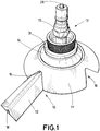
- FIG. 1 a sub-assembly of a device according to the invention is represented. It comprises a vacuum distribution device 10 and a vacuum port 13.
- the vacuum port 13 comprises a body 15 with a connector 28 adapted for being connected to a vacuum pipe 20 (not represented on this figure).
- the vacuum port 13 further comprises a external clamp 31 for being placed on the external side of a vacuum film 21 (not represented on this figure). It also comprises a internal clamp 14 for being placed on the internal side of a vacuum film 21.
- the body 15, the clamps 31, 14 and the connector 28 of the vacuum port 13 are all adapted to form a fluid connection between a vacuum pipe 20 and the internal side of a vacuum film 21 when assembled together as represented on Figure 1 .
- the body, and the clamps 31, 14 comprise at least one vacuum conduit.
- the vacuum distribution device 10 comprises a distribution base 11 and a distribution branch 12.
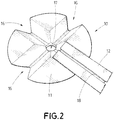
- the distribution base 11 comprises four distribution ports 16 as may also be seen on Figure 2 .
- the distribution base is adapted to provide a fluid connection between a port 17 on its upper face 25 and the distribution ports 16.
- the upper face 25, represented on Figure 3 is adapted to be connected with the internal clamp 14 of the vacuum port 13 so as to ensure a fluid connection between the port 17 of the distribution base 11 and the vacuum pipe 20 through the vacuum port 13.
- the distribution branch 12 and the distribution ports 16 have complementary shapes such that an end of the distribution branch 12 may fit in the distribution port 16 of the distribution base 11.
- the distribution branch 12 has a constant cross-section.
- the distribution branch 12 may be obtained by extrusion.
- the distribution branch 12 comprises a distribution conduit 18 all along its length.
- the distribution conduit 18 is so that is open on its whole length on a face of the distribution branch 12.
- the distribution conduit 18 is open on a face, later referred as lower face, of the distribution branch 12 adapted to be placed against a breathing layer 32 as may be seen on Figure 7 .
- a distribution device 10 according to the invention, and in particular the distribution branch 12, ensures a function of distributing the vacuum along its length under the vacuum film, such that the vacuum is not applied at the one or more punctual locations of the vacuum ports, but rather along distributed lines.
- the distribution branch provides an elongated suction port.
- the distribution conduit 18 opens at one end of the distribution branch 12 into the distribution port 16 of the distribution base 11 such that the distribution conduit 18 provides a fluid connection between the elongated suction port that its distribution conduit 18 form along the lower face of the distribution branch and the distribution port 16 of the distribution base 11.
- the distribution branch 12 has a substantially triangular external cross-section.
- the lower face of the distribution branch 12 is generally flat, except for the opening of the distribution conduit 18.
- the lower face of the distribution branch 12 may not be flat, for example it may be corrugated.
- the upper side of the distribution branch 12 form a rounded transition from one of its side face to the other of its side face, so as to not damage the vacuum film 21 which will be applied against the distribution branch 12 upon application of vacuum at the vacuum port 15.
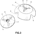
- the upper face 25 of the distribution base 11 is generally round, as represented on Figure 3 . It comprises a hole acting as a port 17 in its center for connecting the distribution ports 16 to the vacuum port 13.
- the upper face 25 comprises three radial ribs 26.
- Figure 3 also shows the lower face of the internal clamp 14 of the vacuum port 13.
- the internal clamp 14 has a round shape and comprises a hole 29 in its middle for connecting the port 17 of the distribution base to the vacuum conduit in the body 15 of the vacuum port 13.
- the internal clamp 14 and the distribution base 11 are adapted to be assembled together so that the hole 29 of the internal clamp 14 and the port 17 of the distribution base 11 are and remain aligned when assembled, and in particular when vacuum is applied.
- the lower face of the internal clamp 14 comprises three radial grooves 27 complementary to the radial ribs 26 of the upper face 25 of the distribution base 11.
- the relative rotation of the internal clamp 14 and the distribution base 11 is also prohibited by this rib and groove assembly, in particular under application of vacuum which tends to press the internal clamp 14 against the distribution base 11.
- FIG 4 a detail of the vacuum port 13 is represented with the body 15 and external clamp 31 on one side and the internal clamp 14 seen from above on the other side.
- the external clamp 31 and the internal clamp 14 are adapted to clamp a vacuum film 21 between them, as can be seen on Figure 6 .
- the upper face of the internal clamp 14 comprises concentric grooves and ribs 30 around its central hole 29, so as to avoid a relative displacement between the external clamp 31 and the internal clamp 14. Indeed a relative movement of the external clamp 31 and the internal clamp 14 may induce creases on the vacuum film which may in turn lead to a lower vacuum quality under the vacuum film 21 or to a non-homogeneous pressure on the composite part under the vacuum film. The external clamp 31 and internal clamp 14 are thus locked when pressed against each other upon application of vacuum, such that no crease may form on the vacuum film clamped between them.
- the lower face (not represented) of the external clamp 31 may comprise grooves and ribs complementary to those of the upper face of the internal clamp 14. In other embodiments, the external clamp 31 and internal clamp 14 may also comprise complementary radial ribs and/or grooves respectively on their lower face and upper face.
- FIG 5 a complete vacuum device 19 according to the invention is represented. Such device is also sometimes called vacuum table. A detail of the device is shown on Figure 6 , such that both figures will be described concurrently in the following text.
- the device 19 comprises an airtight support 23, an airtight vacuum film 21 placed over the support 23, and an airtight seal 22 running all around the periphery of the support 23 and vacuum film 21 so as to airtightly seal the vacuum film to the support 23.
- a breathing layer 32 is placed in between the vacuum film 21 and the support 23. The breathing layer ensures a distribution of vacuum along its whole surface by allowing air and other gases to circulate between it fibers, while the fibers maintain a minimum distance between the vacuum film 21 and the support 23.
- the device further comprises vacuum ports 13 - in this embodiment two vacuum ports 13 - connected to vacuum pipes 20 on one side and on the other side to vacuum distribution devices 10.
- the vacuum pipes are connected to a vacuum source.
- the vacuum ports 13 and vacuum distribution devices may be of the type presented in relation to figures 1-4 .
- the distribution device 10 most at the forefront of Figure 5 comprises two distribution branches 12 connected to two different distribution ports of a distribution base.
- some distribution branches 12 are connected by a first end to a distribution device 10 connected to a vacuum port 13, and by a second end to a connector 24 which is not connected to a vacuum port, and only acts as a connector 24 between two distribution branches 12 so as to form angles along the suction port provided by the distribution branches 12.
- the connector 24 may be obtained by using a distribution base 11 of a distribution device 10.
- a distribution branch 12 may, as shown on Figure 5 be installed between two connectors 24.
- the distribution devices 10, including the distribution base 11 and distribution branches 12 are installed between the breathing layer 32 and the vacuum film 21.
- the distribution branches 12 comprise distribution conduits 18 similar to those presented in relation to figures 1-2 , such that an elongated suction port is provided along a linear profile on the breathing layer. This distribution of the suction port along one or more lines on the breathing layer improves significantly the vacuum attained by a device according the invention.
- the vacuum port 13 provides a vacuum as good as or better than the vacuum obtained with six vacuum ports when no distribution devices according to the invention are used. Therefore in a device according to the invention, the manufacturing of composite parts is simplified and made cheaper. The manufacturing is also of a better quality, because a limited number of crossings of the vacuum film 21 by vacuum ports 13 allows to have less vacuum leaks and less creases on the vacuum film.
- the device 19 also comprises a vacuum sensor 34 for measuring the vacuum attained in the vacuum chamber 35 formed between the vacuum film 21 and the support 23.
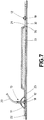
- FIG 7 a cross-section of a device of the type presented in relation to figure 5 is represented. It shows a composite part 33 placed on a support 23.
- the device comprises a seal 22 around the periphery of the support 23.
- a breathing layer 32 is arranged over the composite part 33 and support 23.
- a vacuum film 21 is arranged over the breathing layer 32 and is sealed to the support 23 by the peripheral seal 22.
- a distribution base 11 and a distribution branch 12 may be seen on the left side of the composite part, while a distribution branch may be seen on the right side of the composite parts. All distribution branches are directly, or indirectly through a connector 24 hydraulically connected to a distribution base and a vacuum port.
- the distribution base 11 is connected to a vacuum port 13, itself connected to a vacuum pipe 20.
- the breathing layer allows an air and gas circulation in all parts of a vacuum chamber 35 formed by the airtight support 23, the airtight seal 22 and the airtight vacuum film 21.
- the breathing layer allows an air and gas circulation from the composite part towards the distribution conduits 18 of the distribution branches.
- the proximity and length of the distribution conduits 18 to the composite parts allow a good vacuum distribution in the vacuum chamber 35.
- a first step 50 one or more composite parts 33 are placed on an airtight support 23.
- a seal is arranged at the periphery of the support 23.
- a breathing layer 32 is arranged over the composite parts 33 and support 23.
- one or more distribution devices 10 are arranged on the breathing layer.
- at least one distribution base 11 and one or more distribution branches 12 are arranged on the breathing layer.
- the distribution devices 10 may be arranged on the breathing layer avoiding the areas of the breathing layer directly over the composite parts 33.
- a vacuum film 21 is arranged over the breathing layer 32 and the seal 22.
- a sixth step 55 the vacuum film 21 is sealed to the support 23 with the seal 22, for example by applying pressure to the film 21 along the seal 22, so as to form and airtight chamber between the support 23, the seal 22 and the vacuum film 21.
- a vacuum port 13 is hydraulically connected to each distribution device 10, in particular to each distribution base 11.
- the vacuum film 21 may be opened at this step between the vacuum port and the distribution base, so as to cross the vacuum film 21.
- the vacuum film may alternatively be opened in advance at the locations of the vacuum ports.
- the internal clamp of the vacuum port may also be placed on the distribution base before the step 54, so that this clamp is already on the internal face of the vacuum film.
- step 57 vacuum is applied through the vacuum port(s) 13. This may happen with specific temperature conditions relative to the manufacturing step of the composite parts.
Landscapes
- Engineering & Computer Science (AREA)
- General Engineering & Computer Science (AREA)
- Mechanical Engineering (AREA)
- Chemical & Material Sciences (AREA)
- Composite Materials (AREA)
- Casting Or Compression Moulding Of Plastics Or The Like (AREA)
- Blow-Moulding Or Thermoforming Of Plastics Or The Like (AREA)
- Moulding By Coating Moulds (AREA)
Abstract
Description
- The invention relates to a device and method for manufacturing composite parts under vacuum. In particular, it relates to the manufacturing steps such as autoclave, curing or infusion of composite parts under vacuum-atmospheric pressure.
- In some manufacturing steps of a composite parts, the parts must be subjected to a homogeneous pressure during the application
- Current devices for applying vacuum pressure to an assembly provide a support on which a composite part or assembly may be arranged, a vacuum bag to be applied over the support and composite parts, said vacuum bag being sealed to the support, and a port in the vacuum to apply a vacuum source to a volume comprised between the support and the vacuum bag.
- Such devices do not provide an optimal extraction of gases comprised between the support and the vacuum bag.
- The invention aims to provide an efficient vacuum device and method.
- The invention particularly aims to provide an efficient vacuum device and method for the manufacturing of composite parts.
- The invention aims to provide a vacuum device and method which provide composite parts of high quality.
- The invention aims to provide a vacuum device and method with improved effectiveness.
- The invention also aims to provide an economical device.
- The invention proposes a device for the manufacturing of composite parts comprising:
- an airtight support for supporting one or more composite parts,
- an airtight vacuum film,
- at least one vacuum port adapted to provide a hydraulic connection between a first face of the vacuum film and a second face of the vacuum film,
- an airtight seal for sealing at least a portion of the vacuum film to the support so as to form an airtight chamber,
- hydraulically connected to the vacuum port,
- placed between the support and the vacuum film.
- In the whole text, the term 'vacuum' is used in relation to a lower pressure than an ambient pressure where the device according to the invention is placed. In particular, in usual condition, the device will be at atmospheric pressure, and a vacuum will be a very low pressure compared to atmospheric pressure, such as for example a pressure of between 1 and 50 milliBars.
- The vacuum film (also sometimes called vacuum bag') is an airtight film adapted to be sealed to the support with a seal so as to form an airtight chamber. The vacuum film transmit a pressure differential between its outer face and its inner face to composite parts placed in the vacuum chamber when vacuum is applied in the vacuum chamber.
- The seal may be adapted for sealing a periphery of the vacuum film to the support so as to form an airtight chamber.
- The vacuum distribution device is placed between the support and the vacuum film, in the vacuum chamber. The vacuum distribution device is adapted to, at least locally, maintain the vacuum film at a predetermined distance from the support.
- The vacuum distribution device may comprise a distribution base adapted to be hydraulically connected to the vacuum port.
- More particularly, the distribution base is adapted to be hydraulically connected to the hydraulic connection of the vacuum port.
- The distribution base comprises at least three distribution ports. Each distribution port is adapted to be hydraulically connected to the vacuum port through at least one channel in the distribution base.
- Each distribution port is hydraulically connected to the hydraulic connection of the vacuum port
- The distribution base may comprise one or two distribution ports. The inventors have determined that at least three distribution ports, for example four distribution ports may be beneficial in some embodiments. The distribution base may have more than four distribution ports.
- The distribution ports open between the vacuum film and the support.
- The distribution base is adapted to form a mechanical keyed connection with the vacuum port, at least when a vacuum is applied through the vacuum port.
- When a vacuum is applied through the vacuum port, the vacuum port is brought towards the support. The distribution is placed between the vacuum port and the support. The vacuum port and the distribution base engage in a keyed connection when the vacuum port is maintained against the distribution port.
- The keyed connection is particularly adapted to avoid a relative rotation between the distribution base and the vacuum port. This allows to avoid the formation of crease on the vacuum film, part of which is pinched in between the vacuum port and the distribution base, in particular when vacuum is applied. By having few or no creases on the vacuum film a homogeneous pressure is applied on the composite part and a better vacuum is obtained.
- The keyed connection avoids that creases form on the vacuum layer when the vacuum port is connected, in particular when the vacuum port must be connected by a rotational movement. In particular, creases are avoided because the distribution base and the vacuum port do no need relative attachment such as screwing.
- At least a first of the vacuum port and the distribution base comprises at least one groove and a second of the vacuum port and the distribution base comprises at least one complementary rib.
- The vacuum port and the distribution base comprise complementary shapes. In particular at least a first of the vacuum port and the distribution base may comprise one or more groove and a second of the vacuum port and the distribution base may comprise one or more rib complementary for being engaged with a groove of the first of the vacuum port and the distribution base. In some embodiment the distribution base comprises a plurality of ribs on a face arranged to be placed toward the vacuum port, and the vacuum port comprises complementary grooves on a face arranged to be placed toward the distribution base.
- The vacuum distribution device comprises at least one elongated distribution branch.
- The distribution branch is adapted to distribute the vacuum at one or more points, distant from the distribution base, so as to reach areas of the vacuum chamber that are remote from the distribution base and vacuum port. The number of vacuum ports may thus be limited, while reaching a homogeneous vacuum in the vacuum chamber.
- The distribution branch comprises a distribution conduit along at least part of its length.
- The distribution conduit may be arranged to be hydraulically connected to a distribution port of the distribution base.
- The distribution port may be an opening with a shape and size adapted to receive an end of the distribution branch.
- The distribution port may be used with or without a distribution branch attached to it. The distribution base may be used with a lower number of distribution branches than its number of distribution ports. Thereby the configuration of the vacuum table may be adapted depending on where the distribution base is placed and depending on the size and shape of the composite part.
- The distribution branch comprises one or more suction ports along its length.
- The distribution of the suction ports along the distribution branch may be chosen according to a predetermined pattern. The pattern may vary based on the composite parts to be manufactured.
- The envelope of the distribution conduit may intersect at least one face of the distribution branch at one or more section of said face, so as to form suction port(s).
- The distribution conduit is open on its entire length on a face of the distribution branch so as to form an elongated suction port.
- The vacuum may thus be distributed along the whole length of the distribution branch. Besides, the manufacturing of such distribution branch may be particularly cheap. The distribution branch may be a profile part. In particular, the distribution branch may have a constant cross-section.
- The distribution branch may be an extruded component
- A device according to the invention may further comprise at least two distribution bases, and at least one distribution branch, said distribution branch comprising a first end hydraulically connected to a first distribution base, and a second end hydraulically connected to a second distribution base
- The distribution branch comprises a distribution conduit open to the first end of the distribution branch and to the second end of the distribution branch such that the two distribution bases are in fluid connection.
- A device according to the invention may further comprise a breathing layer arranged between the vacuum film and the support, with the distribution device arranged between the vacuum film and the breathing layer.
- The invention also extends to a method for applying pressure to a composite part, comprising :
- arranging a composite part on an airtight support,
- arranging an airtight vacuum film over the composite part,
- sealing at least a periphery of the vacuum film to the support,
- providing at least one vacuum port adapted to provide a hydraulic connection between a first face of the vacuum film and a second face of the vacuum film,
- arranging a vacuum distribution device between the support and the vacuum film, and
- hydraulically connecting the distribution device to the vacuum port.
- Said breathing layer being adapted to provide a fluid connection both transversally and longitudinally to its thickness,
- More particularly the breathing layer is arranged between the composite part and the vacuum film.
- In such method, a breathing layer may be arranged between the composite part and the vacuum film, and the distribution device may be arranged between the breathing layer and the vacuum film. The distribution device may be placed between the breathing layer and the vacuum film in areas where there is no composite part.
- In a method according to the invention, a vacuum source is connected to the vacuum port. Upon activation of the vacuum source, the gases contained between the vacuum film and the support are sucked up the distribution device, the vacuum port and the vacuum source.
- The invention also extends to other possible combinations of features described in the above description and in the following description relative to the figures. In particular, the invention extends to manufacturing methods comprising features described in relation to devices according to the invention; the invention extends to devices comprising features described in relation to manufacturing methods according to the invention.
- Some specific exemplary embodiments and aspects of the invention are described in the following description in reference to the accompanying figures.
-
Figure 1 is a schematic representation of an embodiment of some parts of a device according to the invention, with a perspective view. -
Figure 2 is a schematic representation of some parts offigure 1 with other view angles. -
Figure 3 is a schematic representation of some parts offigure 1 with other view angles. -
Figure 4 is a schematic representation of some parts offigure 1 with other view angles. -
Figure 5 is a schematic representation of an embodiment of a device according to the invention, with a perspective view. -
Figure 6 is a detailed schematic representation of part of the device represented infigure 5 . -
Figure 7 is a cross-section view of a device according to the invention. -
Figure 8 is a schematic chart of steps of a method according to an embodiment of the invention. - In
Figure 1 , a sub-assembly of a device according to the invention is represented. It comprises avacuum distribution device 10 and avacuum port 13. - The
vacuum port 13 comprises abody 15 with aconnector 28 adapted for being connected to a vacuum pipe 20 (not represented on this figure). Thevacuum port 13 further comprises aexternal clamp 31 for being placed on the external side of a vacuum film 21 (not represented on this figure). It also comprises ainternal clamp 14 for being placed on the internal side of avacuum film 21. Thebody 15, theclamps connector 28 of thevacuum port 13 are all adapted to form a fluid connection between avacuum pipe 20 and the internal side of avacuum film 21 when assembled together as represented onFigure 1 . In particular the body, and theclamps - The
vacuum distribution device 10 comprises adistribution base 11 and adistribution branch 12. - In this embodiment, the
distribution base 11 comprises fourdistribution ports 16 as may also be seen onFigure 2 . The distribution base is adapted to provide a fluid connection between aport 17 on itsupper face 25 and thedistribution ports 16. Theupper face 25, represented onFigure 3 , is adapted to be connected with theinternal clamp 14 of thevacuum port 13 so as to ensure a fluid connection between theport 17 of thedistribution base 11 and thevacuum pipe 20 through thevacuum port 13. - As can be seen on
Figure 2 , thedistribution branch 12 and thedistribution ports 16 have complementary shapes such that an end of thedistribution branch 12 may fit in thedistribution port 16 of thedistribution base 11. In this embodiment, thedistribution branch 12 has a constant cross-section. Thedistribution branch 12 may be obtained by extrusion. Thedistribution branch 12 comprises adistribution conduit 18 all along its length. In the embodiment presented inFigure 1 , thedistribution conduit 18 is so that is open on its whole length on a face of thedistribution branch 12. Thedistribution conduit 18 is open on a face, later referred as lower face, of thedistribution branch 12 adapted to be placed against abreathing layer 32 as may be seen onFigure 7 . Adistribution device 10 according to the invention, and in particular thedistribution branch 12, ensures a function of distributing the vacuum along its length under the vacuum film, such that the vacuum is not applied at the one or more punctual locations of the vacuum ports, but rather along distributed lines. The distribution branch provides an elongated suction port. - With the
distribution branch 12 mounted with one end in adistribution port 16 of thedistribution base 11 as shown onFigure 1 , thedistribution conduit 18 opens at one end of thedistribution branch 12 into thedistribution port 16 of thedistribution base 11 such that thedistribution conduit 18 provides a fluid connection between the elongated suction port that itsdistribution conduit 18 form along the lower face of the distribution branch and thedistribution port 16 of thedistribution base 11. - The
distribution branch 12 has a substantially triangular external cross-section. The lower face of thedistribution branch 12 is generally flat, except for the opening of thedistribution conduit 18. However, in some other embodiments, the lower face of thedistribution branch 12 may not be flat, for example it may be corrugated. The upper side of thedistribution branch 12 form a rounded transition from one of its side face to the other of its side face, so as to not damage thevacuum film 21 which will be applied against thedistribution branch 12 upon application of vacuum at thevacuum port 15. - In this embodiment, the
upper face 25 of thedistribution base 11 is generally round, as represented onFigure 3 . It comprises a hole acting as aport 17 in its center for connecting thedistribution ports 16 to thevacuum port 13. Theupper face 25 comprises threeradial ribs 26.Figure 3 also shows the lower face of theinternal clamp 14 of thevacuum port 13. Theinternal clamp 14 has a round shape and comprises ahole 29 in its middle for connecting theport 17 of the distribution base to the vacuum conduit in thebody 15 of thevacuum port 13. Theinternal clamp 14 and thedistribution base 11 are adapted to be assembled together so that thehole 29 of theinternal clamp 14 and theport 17 of thedistribution base 11 are and remain aligned when assembled, and in particular when vacuum is applied. To ensure the centering of theinternal clamp 14 on thedistribution base 11, the lower face of theinternal clamp 14 comprises threeradial grooves 27 complementary to theradial ribs 26 of theupper face 25 of thedistribution base 11. The relative rotation of theinternal clamp 14 and thedistribution base 11 is also prohibited by this rib and groove assembly, in particular under application of vacuum which tends to press theinternal clamp 14 against thedistribution base 11. - In
figure 4 a detail of thevacuum port 13 is represented with thebody 15 andexternal clamp 31 on one side and theinternal clamp 14 seen from above on the other side. Theexternal clamp 31 and theinternal clamp 14 are adapted to clamp avacuum film 21 between them, as can be seen onFigure 6 . - The upper face of the
internal clamp 14 comprises concentric grooves andribs 30 around itscentral hole 29, so as to avoid a relative displacement between theexternal clamp 31 and theinternal clamp 14. Indeed a relative movement of theexternal clamp 31 and theinternal clamp 14 may induce creases on the vacuum film which may in turn lead to a lower vacuum quality under thevacuum film 21 or to a non-homogeneous pressure on the composite part under the vacuum film. Theexternal clamp 31 andinternal clamp 14 are thus locked when pressed against each other upon application of vacuum, such that no crease may form on the vacuum film clamped between them. The lower face (not represented) of theexternal clamp 31 may comprise grooves and ribs complementary to those of the upper face of theinternal clamp 14. In other embodiments, theexternal clamp 31 andinternal clamp 14 may also comprise complementary radial ribs and/or grooves respectively on their lower face and upper face. - In
figure 5 acomplete vacuum device 19 according to the invention is represented. Such device is also sometimes called vacuum table. A detail of the device is shown onFigure 6 , such that both figures will be described concurrently in the following text. - The
device 19 comprises anairtight support 23, anairtight vacuum film 21 placed over thesupport 23, and anairtight seal 22 running all around the periphery of thesupport 23 andvacuum film 21 so as to airtightly seal the vacuum film to thesupport 23. In between thevacuum film 21 and thesupport 23, abreathing layer 32 is placed. The breathing layer ensures a distribution of vacuum along its whole surface by allowing air and other gases to circulate between it fibers, while the fibers maintain a minimum distance between thevacuum film 21 and thesupport 23. - The device further comprises vacuum ports 13 - in this embodiment two vacuum ports 13 - connected to vacuum
pipes 20 on one side and on the other side to vacuumdistribution devices 10. The vacuum pipes are connected to a vacuum source. - The
vacuum ports 13 and vacuum distribution devices may be of the type presented in relation tofigures 1-4 . Thedistribution device 10 most at the forefront ofFigure 5 comprises twodistribution branches 12 connected to two different distribution ports of a distribution base. In this embodiment, somedistribution branches 12 are connected by a first end to adistribution device 10 connected to avacuum port 13, and by a second end to aconnector 24 which is not connected to a vacuum port, and only acts as aconnector 24 between twodistribution branches 12 so as to form angles along the suction port provided by thedistribution branches 12. Theconnector 24 may be obtained by using adistribution base 11 of adistribution device 10. Adistribution branch 12 may, as shown onFigure 5 be installed between twoconnectors 24. - The
distribution devices 10, including thedistribution base 11 anddistribution branches 12 are installed between thebreathing layer 32 and thevacuum film 21. Thedistribution branches 12 comprisedistribution conduits 18 similar to those presented in relation tofigures 1-2 , such that an elongated suction port is provided along a linear profile on the breathing layer. This distribution of the suction port along one or more lines on the breathing layer improves significantly the vacuum attained by a device according the invention. - In this embodiment of a
device 19 according to the invention, only onevacuum port 13 is used. The risk and amount of vacuum leaks due to vacuum ports is thereby also limited. Thanks to thedistribution devices 10 according to the invention, thevacuum port 13 provides a vacuum as good as or better than the vacuum obtained with six vacuum ports when no distribution devices according to the invention are used. Therefore in a device according to the invention, the manufacturing of composite parts is simplified and made cheaper. The manufacturing is also of a better quality, because a limited number of crossings of thevacuum film 21 byvacuum ports 13 allows to have less vacuum leaks and less creases on the vacuum film. - The
device 19 also comprises avacuum sensor 34 for measuring the vacuum attained in thevacuum chamber 35 formed between thevacuum film 21 and thesupport 23. - In
figure 7 , a cross-section of a device of the type presented in relation tofigure 5 is represented. It shows acomposite part 33 placed on asupport 23. The device comprises aseal 22 around the periphery of thesupport 23. Abreathing layer 32 is arranged over thecomposite part 33 andsupport 23. Avacuum film 21 is arranged over thebreathing layer 32 and is sealed to thesupport 23 by theperipheral seal 22. Between thebreathing layer 32 and the vacuum film 21 adistribution base 11 and adistribution branch 12 may be seen on the left side of the composite part, while a distribution branch may be seen on the right side of the composite parts. All distribution branches are directly, or indirectly through aconnector 24 hydraulically connected to a distribution base and a vacuum port. Thedistribution base 11 is connected to avacuum port 13, itself connected to avacuum pipe 20. - The breathing layer allows an air and gas circulation in all parts of a
vacuum chamber 35 formed by theairtight support 23, theairtight seal 22 and theairtight vacuum film 21. In particular the breathing layer allows an air and gas circulation from the composite part towards thedistribution conduits 18 of the distribution branches. The proximity and length of thedistribution conduits 18 to the composite parts allow a good vacuum distribution in thevacuum chamber 35. - In
figure 8 , steps of a method of manufacturing according to the invention are represented. - In a
first step 50, one or morecomposite parts 33 are placed on anairtight support 23. - In a
second step 51, a seal is arranged at the periphery of thesupport 23. - In a
third step 52, abreathing layer 32 is arranged over thecomposite parts 33 andsupport 23. - In a
fourth step 53, one ormore distribution devices 10 are arranged on the breathing layer. In particular, at least onedistribution base 11 and one ormore distribution branches 12 are arranged on the breathing layer. Thedistribution devices 10 may be arranged on the breathing layer avoiding the areas of the breathing layer directly over thecomposite parts 33. - In a
fifth step 54, avacuum film 21 is arranged over thebreathing layer 32 and theseal 22. - In a
sixth step 55, thevacuum film 21 is sealed to thesupport 23 with theseal 22, for example by applying pressure to thefilm 21 along theseal 22, so as to form and airtight chamber between thesupport 23, theseal 22 and thevacuum film 21. - In a
seventh step 56, avacuum port 13 is hydraulically connected to eachdistribution device 10, in particular to eachdistribution base 11. Thevacuum film 21 may be opened at this step between the vacuum port and the distribution base, so as to cross thevacuum film 21. The vacuum film may alternatively be opened in advance at the locations of the vacuum ports. The internal clamp of the vacuum port may also be placed on the distribution base before thestep 54, so that this clamp is already on the internal face of the vacuum film. - In an
eighth step 57, vacuum is applied through the vacuum port(s) 13. This may happen with specific temperature conditions relative to the manufacturing step of the composite parts. - The invention is not limited to the specific embodiments herein disclosed as examples. The invention also encompasses other embodiments not herein explicitly described, which may comprise various combinations of the features herein described.
Claims (15)
- Device (19) for the manufacturing of composite parts (33) comprising:- an airtight support (23) for supporting one or more composite parts (33),- an airtight vacuum film (21),- at least one vacuum port (13) adapted to provide a hydraulic connection between a first face of the vacuum film (21) and a second face of the vacuum film (21),- an airtight seal (22) for sealing at least a portion of the vacuum film (21) to the support (23) so as to form an airtight chamber (35),characterized in that it further comprises a vacuum distribution device (10) adapted to be:- hydraulically connected to the vacuum port (13),- placed between the support (23) and the vacuum film (21).
- Device according to claim 1, further characterized in that the vacuum distribution device (10) comprises a distribution base (11) adapted to be hydraulically connected to the vacuum port (13).
- Device according to claim 2, further characterized in that the distribution base (11) comprises at least three distribution ports (16).
- Device according to any of claim 2 or 3, further characterized in that the distribution base (11) is adapted to form a mechanical keyed connection with the vacuum port (13), at least when a vacuum is applied through the vacuum port (13).
- Device according to any of claim 2 to 4, further characterized in that at least a first of the vacuum port (13) and the distribution base (11) comprises at least one groove (27) and a second of the vacuum port (13) and the distribution base (11) comprises at least one complementary rib (26).
- Device according to any of claim 1 to 5, further characterized in that the vacuum distribution device (10) comprises at least one elongated distribution branch (12).
- Device according to claim 6, further characterized in that the distribution branch (12) comprises a distribution conduit (18) along at least part of its length.
- Device according to any of claim 6 or 7, further characterized in that the distribution branch (12) comprises one or more suction ports along its length.
- Device according to claim 7, further characterized in that the distribution conduit (18) is open on its entire length on a face of the distribution branch (12) so as to form an elongated suction port.
- Device according to any of claim 6 to 9, further characterized in that the distribution branch (12) is an extruded component.
- Device according to claim 2 and any of claim 6 to 10, further characterized in that it comprises at least two distribution bases (11), and at least one distribution branch (12), said distribution branch (12) comprising a first end hydraulically connected to a first distribution base (11), and a second end hydraulically connected to a second distribution base (11).
- Device according to any of claim 1 to 11, further characterized in that:- it comprises a breathing layer (32) arranged between the vacuum film (21) and the support (23),- the distribution device (10) is arranged between the vacuum film (21) and the breathing layer (32).
- Device according to claims 8 or 9 and 12, further characterized in that at least one suction port is oriented towards the breathing layer (32).
- Method for applying pressure to a composite part (33), comprising :- arranging a composite part (33) on an airtight support (23),- arranging an airtight vacuum film (21) over the composite part (33),- sealing at least a periphery of the vacuum film (21) to the support (23),- providing at least one vacuum port (13) adapted to provide a hydraulic connection between a first face of the vacuum film (21) and a second face of the vacuum film (21),characterized in that it further comprises:- arranging a vacuum distribution device (10) between the support (23) and the vacuum film (21), and- hydraulically connecting the distribution device (10) to the vacuum port (13).
- Method according to claim 14 characterized in that:- a breathing layer (32) is arranged between the composite part (33) and the vacuum film (21),- the distribution device (10) is arranged between the breathing layer (32) and the vacuum film (21).
Priority Applications (2)
| Application Number | Priority Date | Filing Date | Title |
|---|---|---|---|
| ES19382891T ES3014476T3 (en) | 2019-10-10 | 2019-10-10 | Device and method for manufacturing composite parts under vacuum |
| EP19382891.0A EP3804969B1 (en) | 2019-10-10 | 2019-10-10 | Device and method for manufacturing composite parts under vacuum |
Applications Claiming Priority (1)
| Application Number | Priority Date | Filing Date | Title |
|---|---|---|---|
| EP19382891.0A EP3804969B1 (en) | 2019-10-10 | 2019-10-10 | Device and method for manufacturing composite parts under vacuum |
Publications (2)
| Publication Number | Publication Date |
|---|---|
| EP3804969A1 true EP3804969A1 (en) | 2021-04-14 |
| EP3804969B1 EP3804969B1 (en) | 2025-01-01 |
Family
ID=68342881
Family Applications (1)
| Application Number | Title | Priority Date | Filing Date |
|---|---|---|---|
| EP19382891.0A Active EP3804969B1 (en) | 2019-10-10 | 2019-10-10 | Device and method for manufacturing composite parts under vacuum |
Country Status (2)
| Country | Link |
|---|---|
| EP (1) | EP3804969B1 (en) |
| ES (1) | ES3014476T3 (en) |
Cited By (2)
| Publication number | Priority date | Publication date | Assignee | Title |
|---|---|---|---|---|
| EP4480675A1 (en) * | 2023-06-19 | 2024-12-25 | Taikisha Ltd. | Jig and coating apparatus |
| EP4509295A2 (en) * | 2019-11-21 | 2025-02-19 | Spirit Aerosystems (Europe) Limited | Vacuum apparatus |
Citations (3)
| Publication number | Priority date | Publication date | Assignee | Title |
|---|---|---|---|---|
| US4732415A (en) * | 1986-08-29 | 1988-03-22 | The Boeing Company | Non-metallic vacuum probe |
| US5576030A (en) * | 1995-10-02 | 1996-11-19 | Lockheed Corporation | Apparatus for fabricating composite parts |
| GB2528851A (en) * | 2014-07-31 | 2016-02-10 | Vestas Wind Sys As | Self-sealing resin inlet port |
-
2019
- 2019-10-10 EP EP19382891.0A patent/EP3804969B1/en active Active
- 2019-10-10 ES ES19382891T patent/ES3014476T3/en active Active
Patent Citations (3)
| Publication number | Priority date | Publication date | Assignee | Title |
|---|---|---|---|---|
| US4732415A (en) * | 1986-08-29 | 1988-03-22 | The Boeing Company | Non-metallic vacuum probe |
| US5576030A (en) * | 1995-10-02 | 1996-11-19 | Lockheed Corporation | Apparatus for fabricating composite parts |
| GB2528851A (en) * | 2014-07-31 | 2016-02-10 | Vestas Wind Sys As | Self-sealing resin inlet port |
Cited By (2)
| Publication number | Priority date | Publication date | Assignee | Title |
|---|---|---|---|---|
| EP4509295A2 (en) * | 2019-11-21 | 2025-02-19 | Spirit Aerosystems (Europe) Limited | Vacuum apparatus |
| EP4480675A1 (en) * | 2023-06-19 | 2024-12-25 | Taikisha Ltd. | Jig and coating apparatus |
Also Published As
| Publication number | Publication date |
|---|---|
| EP3804969B1 (en) | 2025-01-01 |
| ES3014476T3 (en) | 2025-04-22 |
Similar Documents
| Publication | Publication Date | Title |
|---|---|---|
| KR101669161B1 (en) | Heatable fluid conduit and connector for a heatable fluid conduit | |
| US4554036A (en) | Portable vacuum device and method of using same | |
| EP3804969B1 (en) | Device and method for manufacturing composite parts under vacuum | |
| CA2000708C (en) | Optical fiber built-in type composite insulator and method of producing the same | |
| CN104981670B (en) | vacuum insulator | |
| MX2013012605A (en) | Hose repair clamp. | |
| KR101660694B1 (en) | Vacuum insulated pipe | |
| CN110709636A (en) | Pipe coupling having function of covering pipe | |
| US11052575B2 (en) | Tri-layer bladder and related systems and methods for fabricating composite structures | |
| CN107588256A (en) | Plastic seal accessory | |
| CN108235719A (en) | For pipe end to be connected to the connecting element of air conditioning system components | |
| US3950017A (en) | Leakproof connection for polyethylene tubing | |
| CN106229934B (en) | A kind of cable channel is interior to be blocked | |
| US11644128B2 (en) | Device for the internal monolithic insulation of a welded pipeline joint | |
| US5341567A (en) | Method of making clean socket fit connection | |
| CN104858806B (en) | Vacuum clamp | |
| TW201712229A (en) | Vacuum pump | |
| US6325388B1 (en) | Gasket with integral channel and port seal | |
| US4863197A (en) | High-pressure end fitting | |
| GB2528851A (en) | Self-sealing resin inlet port | |
| CN215488081U (en) | Airtight isolation wall-through isolator device | |
| US6447018B1 (en) | Boltless pipe connector | |
| CN210196736U (en) | Air bed that leakproofness is good is with grafting structure | |
| CN215750569U (en) | Needle tube adsorption combined mechanism | |
| CA3164692A1 (en) | Expandable pipe spool |
Legal Events
| Date | Code | Title | Description |
|---|---|---|---|
| PUAI | Public reference made under article 153(3) epc to a published international application that has entered the european phase |
Free format text: ORIGINAL CODE: 0009012 |
|
| STAA | Information on the status of an ep patent application or granted ep patent |
Free format text: STATUS: THE APPLICATION HAS BEEN PUBLISHED |
|
| AK | Designated contracting states |
Kind code of ref document: A1 Designated state(s): AL AT BE BG CH CY CZ DE DK EE ES FI FR GB GR HR HU IE IS IT LI LT LU LV MC MK MT NL NO PL PT RO RS SE SI SK SM TR |
|
| AX | Request for extension of the european patent |
Extension state: BA ME |
|
| STAA | Information on the status of an ep patent application or granted ep patent |
Free format text: STATUS: REQUEST FOR EXAMINATION WAS MADE |
|
| 17P | Request for examination filed |
Effective date: 20210928 |
|
| RBV | Designated contracting states (corrected) |
Designated state(s): AL AT BE BG CH CY CZ DE DK EE ES FI FR GB GR HR HU IE IS IT LI LT LU LV MC MK MT NL NO PL PT RO RS SE SI SK SM TR |
|
| RIC1 | Information provided on ipc code assigned before grant |
Ipc: F16L 41/03 20060101ALI20230629BHEP Ipc: F16L 41/02 20060101ALI20230629BHEP Ipc: F16L 37/252 20060101ALI20230629BHEP Ipc: B29C 70/54 20060101ALI20230629BHEP Ipc: B29C 70/44 20060101AFI20230629BHEP |
|
| GRAP | Despatch of communication of intention to grant a patent |
Free format text: ORIGINAL CODE: EPIDOSNIGR1 |
|
| STAA | Information on the status of an ep patent application or granted ep patent |
Free format text: STATUS: GRANT OF PATENT IS INTENDED |
|
| INTG | Intention to grant announced |
Effective date: 20230822 |
|
| GRAJ | Information related to disapproval of communication of intention to grant by the applicant or resumption of examination proceedings by the epo deleted |
Free format text: ORIGINAL CODE: EPIDOSDIGR1 |
|
| STAA | Information on the status of an ep patent application or granted ep patent |
Free format text: STATUS: REQUEST FOR EXAMINATION WAS MADE |
|
| INTC | Intention to grant announced (deleted) | ||
| GRAP | Despatch of communication of intention to grant a patent |
Free format text: ORIGINAL CODE: EPIDOSNIGR1 |
|
| STAA | Information on the status of an ep patent application or granted ep patent |
Free format text: STATUS: GRANT OF PATENT IS INTENDED |
|
| INTG | Intention to grant announced |
Effective date: 20231221 |
|
| GRAJ | Information related to disapproval of communication of intention to grant by the applicant or resumption of examination proceedings by the epo deleted |
Free format text: ORIGINAL CODE: EPIDOSDIGR1 |
|
| GRAL | Information related to payment of fee for publishing/printing deleted |
Free format text: ORIGINAL CODE: EPIDOSDIGR3 |
|
| GRAS | Grant fee paid |
Free format text: ORIGINAL CODE: EPIDOSNIGR3 |
|
| STAA | Information on the status of an ep patent application or granted ep patent |
Free format text: STATUS: REQUEST FOR EXAMINATION WAS MADE |
|
| GRAP | Despatch of communication of intention to grant a patent |
Free format text: ORIGINAL CODE: EPIDOSNIGR1 |
|
| STAA | Information on the status of an ep patent application or granted ep patent |
Free format text: STATUS: GRANT OF PATENT IS INTENDED |
|
| INTC | Intention to grant announced (deleted) | ||
| INTG | Intention to grant announced |
Effective date: 20240416 |
|
| GRAS | Grant fee paid |
Free format text: ORIGINAL CODE: EPIDOSNIGR3 |
|
| GRAA | (expected) grant |
Free format text: ORIGINAL CODE: 0009210 |
|
| STAA | Information on the status of an ep patent application or granted ep patent |
Free format text: STATUS: THE PATENT HAS BEEN GRANTED |
|
| AK | Designated contracting states |
Kind code of ref document: B1 Designated state(s): AL AT BE BG CH CY CZ DE DK EE ES FI FR GB GR HR HU IE IS IT LI LT LU LV MC MK MT NL NO PL PT RO RS SE SI SK SM TR |
|
| REG | Reference to a national code |
Ref country code: GB Ref legal event code: FG4D |
|
| REG | Reference to a national code |
Ref country code: CH Ref legal event code: EP |
|
| REG | Reference to a national code |
Ref country code: DE Ref legal event code: R096 Ref document number: 602019064216 Country of ref document: DE |
|
| REG | Reference to a national code |
Ref country code: IE Ref legal event code: FG4D |
|
| REG | Reference to a national code |
Ref country code: ES Ref legal event code: FG2A Ref document number: 3014476 Country of ref document: ES Kind code of ref document: T3 Effective date: 20250422 |
|
| REG | Reference to a national code |
Ref country code: LT Ref legal event code: MG9D |
|
| REG | Reference to a national code |
Ref country code: NL Ref legal event code: MP Effective date: 20250101 |
|
| REG | Reference to a national code |
Ref country code: AT Ref legal event code: MK05 Ref document number: 1755810 Country of ref document: AT Kind code of ref document: T Effective date: 20250101 |
|
| PG25 | Lapsed in a contracting state [announced via postgrant information from national office to epo] |
Ref country code: NL Free format text: LAPSE BECAUSE OF FAILURE TO SUBMIT A TRANSLATION OF THE DESCRIPTION OR TO PAY THE FEE WITHIN THE PRESCRIBED TIME-LIMIT Effective date: 20250101 |
|
| PG25 | Lapsed in a contracting state [announced via postgrant information from national office to epo] |
Ref country code: FI Free format text: LAPSE BECAUSE OF FAILURE TO SUBMIT A TRANSLATION OF THE DESCRIPTION OR TO PAY THE FEE WITHIN THE PRESCRIBED TIME-LIMIT Effective date: 20250101 |
|
| PG25 | Lapsed in a contracting state [announced via postgrant information from national office to epo] |
Ref country code: PL Free format text: LAPSE BECAUSE OF FAILURE TO SUBMIT A TRANSLATION OF THE DESCRIPTION OR TO PAY THE FEE WITHIN THE PRESCRIBED TIME-LIMIT Effective date: 20250101 |
|
| PG25 | Lapsed in a contracting state [announced via postgrant information from national office to epo] |
Ref country code: NO Free format text: LAPSE BECAUSE OF FAILURE TO SUBMIT A TRANSLATION OF THE DESCRIPTION OR TO PAY THE FEE WITHIN THE PRESCRIBED TIME-LIMIT Effective date: 20250401 Ref country code: IS Free format text: LAPSE BECAUSE OF FAILURE TO SUBMIT A TRANSLATION OF THE DESCRIPTION OR TO PAY THE FEE WITHIN THE PRESCRIBED TIME-LIMIT Effective date: 20250501 |
|
| PG25 | Lapsed in a contracting state [announced via postgrant information from national office to epo] |
Ref country code: HR Free format text: LAPSE BECAUSE OF FAILURE TO SUBMIT A TRANSLATION OF THE DESCRIPTION OR TO PAY THE FEE WITHIN THE PRESCRIBED TIME-LIMIT Effective date: 20250101 |
|
| PG25 | Lapsed in a contracting state [announced via postgrant information from national office to epo] |
Ref country code: LV Free format text: LAPSE BECAUSE OF FAILURE TO SUBMIT A TRANSLATION OF THE DESCRIPTION OR TO PAY THE FEE WITHIN THE PRESCRIBED TIME-LIMIT Effective date: 20250101 Ref country code: PT Free format text: LAPSE BECAUSE OF FAILURE TO SUBMIT A TRANSLATION OF THE DESCRIPTION OR TO PAY THE FEE WITHIN THE PRESCRIBED TIME-LIMIT Effective date: 20250502 |
|
| PG25 | Lapsed in a contracting state [announced via postgrant information from national office to epo] |
Ref country code: BG Free format text: LAPSE BECAUSE OF FAILURE TO SUBMIT A TRANSLATION OF THE DESCRIPTION OR TO PAY THE FEE WITHIN THE PRESCRIBED TIME-LIMIT Effective date: 20250101 |
|
| PG25 | Lapsed in a contracting state [announced via postgrant information from national office to epo] |
Ref country code: AT Free format text: LAPSE BECAUSE OF FAILURE TO SUBMIT A TRANSLATION OF THE DESCRIPTION OR TO PAY THE FEE WITHIN THE PRESCRIBED TIME-LIMIT Effective date: 20250101 |
|
| PG25 | Lapsed in a contracting state [announced via postgrant information from national office to epo] |
Ref country code: CZ Free format text: LAPSE BECAUSE OF FAILURE TO SUBMIT A TRANSLATION OF THE DESCRIPTION OR TO PAY THE FEE WITHIN THE PRESCRIBED TIME-LIMIT Effective date: 20250101 |
|
| PG25 | Lapsed in a contracting state [announced via postgrant information from national office to epo] |
Ref country code: SE Free format text: LAPSE BECAUSE OF FAILURE TO SUBMIT A TRANSLATION OF THE DESCRIPTION OR TO PAY THE FEE WITHIN THE PRESCRIBED TIME-LIMIT Effective date: 20250101 |
|
| REG | Reference to a national code |
Ref country code: DE Ref legal event code: R097 Ref document number: 602019064216 Country of ref document: DE |
|
| PG25 | Lapsed in a contracting state [announced via postgrant information from national office to epo] |
Ref country code: SM Free format text: LAPSE BECAUSE OF FAILURE TO SUBMIT A TRANSLATION OF THE DESCRIPTION OR TO PAY THE FEE WITHIN THE PRESCRIBED TIME-LIMIT Effective date: 20250101 |
|
| PG25 | Lapsed in a contracting state [announced via postgrant information from national office to epo] |
Ref country code: DK Free format text: LAPSE BECAUSE OF FAILURE TO SUBMIT A TRANSLATION OF THE DESCRIPTION OR TO PAY THE FEE WITHIN THE PRESCRIBED TIME-LIMIT Effective date: 20250101 |
|
| PG25 | Lapsed in a contracting state [announced via postgrant information from national office to epo] |
Ref country code: IT Free format text: LAPSE BECAUSE OF FAILURE TO SUBMIT A TRANSLATION OF THE DESCRIPTION OR TO PAY THE FEE WITHIN THE PRESCRIBED TIME-LIMIT Effective date: 20250101 |
|
| PG25 | Lapsed in a contracting state [announced via postgrant information from national office to epo] |
Ref country code: EE Free format text: LAPSE BECAUSE OF FAILURE TO SUBMIT A TRANSLATION OF THE DESCRIPTION OR TO PAY THE FEE WITHIN THE PRESCRIBED TIME-LIMIT Effective date: 20250101 |
|
| PG25 | Lapsed in a contracting state [announced via postgrant information from national office to epo] |
Ref country code: RO Free format text: LAPSE BECAUSE OF FAILURE TO SUBMIT A TRANSLATION OF THE DESCRIPTION OR TO PAY THE FEE WITHIN THE PRESCRIBED TIME-LIMIT Effective date: 20250101 |
|
| PG25 | Lapsed in a contracting state [announced via postgrant information from national office to epo] |
Ref country code: SK Free format text: LAPSE BECAUSE OF FAILURE TO SUBMIT A TRANSLATION OF THE DESCRIPTION OR TO PAY THE FEE WITHIN THE PRESCRIBED TIME-LIMIT Effective date: 20250101 |
|
| PLBE | No opposition filed within time limit |
Free format text: ORIGINAL CODE: 0009261 |
|
| STAA | Information on the status of an ep patent application or granted ep patent |
Free format text: STATUS: NO OPPOSITION FILED WITHIN TIME LIMIT |
|
| 26N | No opposition filed |
Effective date: 20251002 |
|
| PGFP | Annual fee paid to national office [announced via postgrant information from national office to epo] |
Ref country code: DE Payment date: 20251021 Year of fee payment: 7 |
|
| PGFP | Annual fee paid to national office [announced via postgrant information from national office to epo] |
Ref country code: GB Payment date: 20251022 Year of fee payment: 7 |
|
| PGFP | Annual fee paid to national office [announced via postgrant information from national office to epo] |
Ref country code: FR Payment date: 20251030 Year of fee payment: 7 |
|
| PGFP | Annual fee paid to national office [announced via postgrant information from national office to epo] |
Ref country code: ES Payment date: 20251216 Year of fee payment: 7 |