EP3804870A1 - Rolling mill and method for setting rolling mill - Google Patents
Rolling mill and method for setting rolling mill Download PDFInfo
- Publication number
- EP3804870A1 EP3804870A1 EP19810340.0A EP19810340A EP3804870A1 EP 3804870 A1 EP3804870 A1 EP 3804870A1 EP 19810340 A EP19810340 A EP 19810340A EP 3804870 A1 EP3804870 A1 EP 3804870A1
- Authority
- EP
- European Patent Office
- Prior art keywords
- roll
- work
- chocks
- rolling direction
- rolls
- Prior art date
- Legal status (The legal status is an assumption and is not a legal conclusion. Google has not performed a legal analysis and makes no representation as to the accuracy of the status listed.)
- Granted
Links
- 238000005096 rolling process Methods 0.000 title claims abstract description 571
- 238000000034 method Methods 0.000 title claims description 65
- 238000005259 measurement Methods 0.000 claims abstract description 101
- 238000003825 pressing Methods 0.000 claims abstract description 45
- 238000005452 bending Methods 0.000 claims description 69
- 238000001514 detection method Methods 0.000 claims description 31
- 230000009467 reduction Effects 0.000 claims description 17
- 238000004364 calculation method Methods 0.000 description 43
- 238000007796 conventional method Methods 0.000 description 8
- 238000009826 distribution Methods 0.000 description 8
- 230000003247 decreasing effect Effects 0.000 description 7
- 238000012545 processing Methods 0.000 description 6
- 230000008859 change Effects 0.000 description 5
- 239000000463 material Substances 0.000 description 4
- 238000012935 Averaging Methods 0.000 description 3
- 229910000831 Steel Inorganic materials 0.000 description 3
- 230000007246 mechanism Effects 0.000 description 3
- 239000010959 steel Substances 0.000 description 3
- 238000000429 assembly Methods 0.000 description 2
- 230000000712 assembly Effects 0.000 description 2
- 230000000694 effects Effects 0.000 description 2
- 238000004519 manufacturing process Methods 0.000 description 2
- 239000002184 metal Substances 0.000 description 2
- 239000008186 active pharmaceutical agent Substances 0.000 description 1
- 238000004458 analytical method Methods 0.000 description 1
- 238000013459 approach Methods 0.000 description 1
- 239000000470 constituent Substances 0.000 description 1
- 238000006073 displacement reaction Methods 0.000 description 1
- 238000002474 experimental method Methods 0.000 description 1
- 238000005098 hot rolling Methods 0.000 description 1
- 238000003754 machining Methods 0.000 description 1
- 238000012986 modification Methods 0.000 description 1
- 230000004048 modification Effects 0.000 description 1
- 238000002360 preparation method Methods 0.000 description 1
- 230000000717 retained effect Effects 0.000 description 1
Images


Classifications
-
- B—PERFORMING OPERATIONS; TRANSPORTING
- B21—MECHANICAL METAL-WORKING WITHOUT ESSENTIALLY REMOVING MATERIAL; PUNCHING METAL
- B21B—ROLLING OF METAL
- B21B29/00—Counter-pressure devices acting on rolls to inhibit deflection of same under load, e.g. backing rolls ; Roll bending devices, e.g. hydraulic actuators acting on roll shaft ends
-
- B—PERFORMING OPERATIONS; TRANSPORTING
- B21—MECHANICAL METAL-WORKING WITHOUT ESSENTIALLY REMOVING MATERIAL; PUNCHING METAL
- B21B—ROLLING OF METAL
- B21B13/00—Metal-rolling stands, i.e. an assembly composed of a stand frame, rolls, and accessories
- B21B13/14—Metal-rolling stands, i.e. an assembly composed of a stand frame, rolls, and accessories having counter-pressure devices acting on rolls to inhibit deflection of same under load; Back-up rolls
- B21B13/145—Lateral support devices for rolls acting mainly in a direction parallel to the movement of the product
-
- B—PERFORMING OPERATIONS; TRANSPORTING
- B21—MECHANICAL METAL-WORKING WITHOUT ESSENTIALLY REMOVING MATERIAL; PUNCHING METAL
- B21B—ROLLING OF METAL
- B21B31/00—Rolling stand structures; Mounting, adjusting, or interchanging rolls, roll mountings, or stand frames
- B21B31/02—Rolling stand frames or housings; Roll mountings ; Roll chocks
-
- B—PERFORMING OPERATIONS; TRANSPORTING
- B21—MECHANICAL METAL-WORKING WITHOUT ESSENTIALLY REMOVING MATERIAL; PUNCHING METAL
- B21B—ROLLING OF METAL
- B21B37/00—Control devices or methods specially adapted for metal-rolling mills or the work produced thereby
- B21B37/28—Control of flatness or profile during rolling of strip, sheets or plates
- B21B37/30—Control of flatness or profile during rolling of strip, sheets or plates using roll camber control
-
- B—PERFORMING OPERATIONS; TRANSPORTING
- B21—MECHANICAL METAL-WORKING WITHOUT ESSENTIALLY REMOVING MATERIAL; PUNCHING METAL
- B21B—ROLLING OF METAL
- B21B37/00—Control devices or methods specially adapted for metal-rolling mills or the work produced thereby
- B21B37/68—Camber or steering control for strip, sheets or plates, e.g. preventing meandering
-
- B—PERFORMING OPERATIONS; TRANSPORTING
- B21—MECHANICAL METAL-WORKING WITHOUT ESSENTIALLY REMOVING MATERIAL; PUNCHING METAL
- B21C—MANUFACTURE OF METAL SHEETS, WIRE, RODS, TUBES OR PROFILES, OTHERWISE THAN BY ROLLING; AUXILIARY OPERATIONS USED IN CONNECTION WITH METAL-WORKING WITHOUT ESSENTIALLY REMOVING MATERIAL
- B21C51/00—Measuring, gauging, indicating, counting, or marking devices specially adapted for use in the production or manipulation of material in accordance with subclasses B21B - B21F
-
- B—PERFORMING OPERATIONS; TRANSPORTING
- B21—MECHANICAL METAL-WORKING WITHOUT ESSENTIALLY REMOVING MATERIAL; PUNCHING METAL
- B21B—ROLLING OF METAL
- B21B13/00—Metal-rolling stands, i.e. an assembly composed of a stand frame, rolls, and accessories
- B21B13/02—Metal-rolling stands, i.e. an assembly composed of a stand frame, rolls, and accessories with axes of rolls arranged horizontally
- B21B2013/025—Quarto, four-high stands
-
- B—PERFORMING OPERATIONS; TRANSPORTING
- B21—MECHANICAL METAL-WORKING WITHOUT ESSENTIALLY REMOVING MATERIAL; PUNCHING METAL
- B21B—ROLLING OF METAL
- B21B13/00—Metal-rolling stands, i.e. an assembly composed of a stand frame, rolls, and accessories
- B21B13/02—Metal-rolling stands, i.e. an assembly composed of a stand frame, rolls, and accessories with axes of rolls arranged horizontally
- B21B2013/028—Sixto, six-high stands
-
- B—PERFORMING OPERATIONS; TRANSPORTING
- B21—MECHANICAL METAL-WORKING WITHOUT ESSENTIALLY REMOVING MATERIAL; PUNCHING METAL
- B21B—ROLLING OF METAL
- B21B2269/00—Roll bending or shifting
- B21B2269/02—Roll bending; vertical bending of rolls
- B21B2269/04—Work roll bending
-
- B—PERFORMING OPERATIONS; TRANSPORTING
- B21—MECHANICAL METAL-WORKING WITHOUT ESSENTIALLY REMOVING MATERIAL; PUNCHING METAL
- B21B—ROLLING OF METAL
- B21B2273/00—Path parameters
- B21B2273/04—Lateral deviation, meandering, camber of product
-
- B—PERFORMING OPERATIONS; TRANSPORTING
- B21—MECHANICAL METAL-WORKING WITHOUT ESSENTIALLY REMOVING MATERIAL; PUNCHING METAL
- B21B—ROLLING OF METAL
- B21B31/00—Rolling stand structures; Mounting, adjusting, or interchanging rolls, roll mountings, or stand frames
- B21B31/16—Adjusting or positioning rolls
- B21B31/18—Adjusting or positioning rolls by moving rolls axially
- B21B31/185—Adjusting or positioning rolls by moving rolls axially and by crossing rolls
-
- B—PERFORMING OPERATIONS; TRANSPORTING
- B21—MECHANICAL METAL-WORKING WITHOUT ESSENTIALLY REMOVING MATERIAL; PUNCHING METAL
- B21B—ROLLING OF METAL
- B21B38/00—Methods or devices for measuring, detecting or monitoring specially adapted for metal-rolling mills, e.g. position detection, inspection of the product
Definitions
- the present invention relates to a rolling mill that rolls a workpiece, and a method for setting the rolling mill.
- zigzagging of a steel plate occurs as a phenomenon that is the cause of rolling trouble.
- a thrust force that is generated at a minute cross (also referred to as "roll skew") between rolls of a rolling apparatus is one cause of zigzagging of a steel plate, and it is difficult to directly measure such a thrust force. Therefore, in the past it has been proposed to measure a thrust counterforce that is detected as a counterforce that is the total value of thrust forces generated between rolls or a roll skew angle, and identify the thrust force generated between rolls based on the thrust counterforce or the roll skew angle and perform zigzagging control of the steel plate.
- Patent Document 1 discloses a plate rolling method which measures a thrust counterforce in the axial direction of a roll and a load in a vertical direction, determines either one of, or both of, a reduction position zero point and deformation properties of the rolling mill, and sets the reduction position at the time of rolling execution and controls rolling.
- Patent Document 2 discloses a zigzagging control method that calculates a thrust force generated at a roll based on an inter-roll minute cross angle (skew angle) that is measured using a distance sensor provided inside a rolling mill and, based on the thrust force, calculates a differential load component that is a cause of zigzagging based on a load measurement value in the vertical direction and performs reduction leveling control.
- skew angle inter-roll minute cross angle
- Patent Document 3 discloses a cross-point correcting device which corrects a deviation in a point (cross point) at which the central axes of upper and lower rolls cross in the horizontal direction in a pair cross rolling mill.
- the apparatus includes an actuator that absorbs play that arises between a crosshead and roll chocks, and a detector that detects roll chock positions, and corrects a deviation in the cross point based on the roll chock positions.
- Patent Document 1 Although it is necessary to perform measurement of the thrust counterforce of rolls other than a backup roll at a time of reduction position zero point adjustment and during rolling, in the case of measuring thrust counterforces during rolling, in some cases characteristics such as the working point of the thrust counterforce change depending on changes in the rolling conditions such as the rolling load, and asymmetric deformation that accompanies the thrust force cannot be correctly identified. Therefore, there is the possibility that reduction leveling control cannot be accurately performed.
- a roll skew angle is determined based on a distance in the horizontal direction of a roll that is measured by a distance sensor such as a vortex sensor.
- a distance sensor such as a vortex sensor.
- a roll vibrates in the horizontal direction depending on the degree of machining precision such as the eccentricity or cylindricity of a roll body length portion, and chock positions in the horizontal direction fluctuate due to impact at the time of biting at the start of rolling and the like, it is difficult to accurately measure the horizontal displacement of a roll which is a factor that causes the generation of a thrust force.
- the coefficient of friction of a roll is constantly changing because the degree of roughness of a roll changes with time as the number of rolled workpieces increases. Therefore, calculation of a thrust force without identification of the coefficient of friction cannot be performed accurately based on only a roll skew angle measurement.
- the zero point of the reduction position in a kiss roll state is adjusted by an operator based on the values of vertical roll loads on the work side and the drive side.
- an inter-roll thrust force is generated due to an inter-roll minute cross, in some cases a difference arises between the vertical roll load on the work side and the vertical roll load on the drive side, and the reduction position zero point adjustment cannot be correctly performed.
- the present invention has been made in view of the problems described above, and an objective of the present invention is to provide a novel and improved method for setting a rolling mill, and a rolling mill, before zero point of reduction position adjustment or before starting rolling, by reducing thrust forces generated between rolls and suppressing the occurrence of zigzagging and camber of a workpiece.
- a rolling mill of four-high or more that includes a plurality of rolls including at least a pair of work rolls and a pair of backup rolls supporting the work rolls, wherein any one roll among respective rolls arranged in a vertical direction is adopted as a reference roll
- the rolling mill including: a measurement apparatus which measures at least rolling direction forces in a rolling direction which act on roll chocks on a work side and roll chocks on a drive side of each of the rolls other than the backup rolls; a pressing apparatus which, with respect to at least roll chocks of the rolls other than the reference roll, is provided on either one of an entrance side and an exit side in the rolling direction, the pressing apparatus pressing a workpiece in the rolling direction; a driving apparatus which, with respect to at least roll chocks of the rolls other than the reference roll, is provided so as to face the pressing apparatus in the rolling direction, the driving apparatus moving a workpiece in the rolling direction; and a position control unit that fixes a rolling direction position of roll
- a roll located at a lowermost part or an uppermost part in the vertical direction among the plurality of rolls may be adopted as the reference roll.
- the rolling mill may be provided a bending apparatus that imparts a bending force to the rolls, the position control unit sets a roll gap between the work rolls in an open state, and imparts a bending force by means of the bending apparatus to the roll chocks of the work rolls.
- the driving apparatus may be a hydraulic cylinder comprising a roll chock position detection apparatus.
- a method for setting a rolling mill the rolling mill being a rolling mill of four-high or more that includes a plurality of rolls including at least a pair of work rolls and a pair of backup rolls supporting the work rolls, the method for setting a rolling mill being executed before reduction position zero point adjustment or before starting rolling, wherein any one roll among respective rolls arranged in a vertical direction is adopted as a reference roll, the method including: measuring at least rolling direction forces in a rolling direction that act on roll chocks on a work side and roll chocks on a drive side of the rolls other than the backup rolls, and fixing a rolling direction position of roll chocks of the reference roll as a reference position, and moving roll chocks of the rolls other than the reference roll in a rolling direction of a workpiece to adjust positions of the roll chocks so that a rolling direction force difference that is a difference between a rolling direction force measured on the work side and a rolling direction force measured on the drive side
- a roll located at a lowermost part or an uppermost part in the vertical direction among the plurality of rolls may be adopted as the reference roll.
- the roll chocks of the rolls may be moved in the rolling direction of the workpiece to adjust the positions of the roll chocks so that the rolling direction force differences arising at the rolls that are adjacent fall within an allowable range, and at such time, the roll chocks of the rolls for which the position of the roll chocks is already adjusted may be controlled simultaneously and in a same direction while maintaining relative positions with respect to the roll chocks of the roll that is being adjusted.
- the method may including performing: a first adjustment in which a roll gap between the work rolls is set in an open state, and with respect to each of the upper roll assembly and the lower roll assembly, positions of the roll chocks of the work roll and the roll chocks of the backup roll are adjusted, and after the first adjustment ends, a second adjustment in which the work rolls are set in a kiss roll state, and either one of the upper roll assembly and the lower roll assembly is adopted as a reference roll assembly, and positions of the roll chocks of each roll of the other roll assembly are adjusted by controlling the roll chocks simultaneously and in a same direction while maintaining relative positions between the roll chocks; and in the first adjustment, with respect to each of the upper roll assembly and the lower roll assembly,
- the rolling mill that is a six-high rolling mill comprising intermediate rolls between the work rolls and the backup rolls, respectively, a plurality of rolls provided on an upper side in the vertical direction with respect to the workpiece are adopted as an upper roll assembly, and a plurality of rolls provided on a lower side in the vertical direction with respect to the workpiece are adopted as a lower roll assembly;
- the method may including performing: a first adjustment in which a roll gap between the work rolls is set in an open state, and with respect to each of the upper roll assembly and the lower roll assembly, positions of the roll chocks of the intermediate roll and the roll chocks of the backup roll are adjusted, after the first adjustment ends, a second adjustment in which the roll gap between the work rolls is maintained in an open state, and with respect to each of the upper roll assembly and the lower roll assembly, positions of the roll chocks of the intermediate roll and the roll chocks of the work roll are adjusted, and after the second adjustment ends, a third adjustment in which the work rolls are set in a kiss roll state, either one of the upper roll
- thrust forces generated between rolls can be reduced and the occurrence of zigzagging and camber of a workpiece can be suppressed.
- An objective of a rolling mill as well as a method for setting the rolling mill according to the embodiments of the present invention is to eliminate thrust forces generated between rolls, and enable the stable production of products without zigzagging and camber or with extremely little zigzagging and camber.
- Figure 1 a schematic side view and a schematic front view of a rolling mill are illustrated for describing a thrust force and a thrust counterforce which are generated between rolls of a rolling mill during rolling of a workpiece S.
- the work side in the axial direction of rolls is represented by "WS”
- the drive side is represented by "DS”.
- the rolling mill illustrated in Figure 1 has a pair of work rolls consisting of an upper work roll 1 and a lower work roll 2, and a pair of backup rolls consisting of an upper backup roll 3 that supports the upper work roll 1 in the vertical direction (Z direction) and a lower backup roll 4 that supports the lower work roll 2 in the vertical direction.
- the work side of the upper work roll 1 is supported by an upper work roll chock 5a, and the drive side of the upper work roll 1 is supported by an upper work roll chock 5b.
- the work side of the lower work roll 2 is supported by a lower work roll chock 6a, and the drive side of the lower work roll 2 is supported by a lower work roll chock 6b.
- the work side of the upper backup roll 3 is supported by an upper backup roll chock 7a, and the drive side of the upper backup roll 3 is supported by an upper backup roll chock 7b.
- the work side of the lower backup roll 4 is supported by a lower backup roll chock 8a, and the drive side of the lower backup roll 4 is supported by a lower backup roll chock 8b.
- the upper work roll 1, the lower work roll 2, the upper backup roll 3 and the lower backup roll 4 are arranged in a manner in which the axial directions of the respective rolls are parallel, so as to be orthogonal with the conveyance direction of the workpiece S.
- a roll rotates slightly about an axis (Z-axis) that is parallel with the vertical direction and a deviation arises between the axial directions of the upper work roll 1 and the upper backup roll 3, or a deviation arises between the axial directions of the lower work roll 2 and the lower backup roll 4
- a thrust force that acts in the axial direction of the rolls arises between the work roll and the backup roll.
- An inter-roll thrust force gives an extra moment to the rolls, and causes asymmetric roll deformation to occur due to the aforementioned moment.
- the asymmetric roll deformation is a factor that causes the rolling to enter an unstable state, and for example gives rise to zigzagging or camber.
- the inter-roll thrust force is generated as a result of an inter-roll cross angle arising due to the occurrence of a deviation between the axial directions of a work roll and a backup roll. For example, let us assume that an inter-roll cross angle arises between the lower work roll 2 and the lower backup roll 4. At such time, a thrust force is generated between the lower work roll 2 and the lower backup roll 4, and as a result, a moment occurs at the lower backup roll 4, and the load distribution between the rolls changes to balance with the moment, and thus an asymmetric roll deformation occurs. Zigzagging or camber or the like is caused by the asymmetric roll deformation, and the rolling becomes unstable.
- an objective of the present invention is, during rolling of a workpiece by a rolling mill, to adjust roll chock positions of each roll so that inter-roll thrust forces generated between rolls are eliminated, based on a left-right difference in rolling direction forces before reduction position zero point adjustment or before the start of rolling, and thereby enable the stable production of products without zigzagging and camber or with extremely little zigzagging and camber.
- Figure 2A is an explanatory drawing illustrating the configuration of the rolling mill according to the present embodiment, and an apparatus for controlling the rolling mill.
- Figure 2B is an explanatory drawing illustrating rolling direction force measurement apparatuses that are arranged on an entrance side and an exit side of the rolling mill illustrated in Figure 2A . Note that, it is assumed that the rolling mill illustrated in Figure 2A is shown in a state as seen from the work side in the axial direction of the rolls. Further, in Figure 2A , a configuration in a case where the lower backup roll is adopted as the reference roll is illustrated. Note that, the reference roll is preferably a roll for which the area of contact between the chocks and the housing is large, and which is located at the lowermost part or the uppermost part, where the position is stable.
- the rolling mill illustrated in Figure 2A is a four-high rolling mill having a pair of work rolls 1 and 2 and a pair of backup rolls 3 and 4 that support the pair of work rolls 1 and 2.
- the upper work roll 1, the lower work roll 2, the upper backup roll 3 and the lower backup roll 4 are a plurality of rolls which are arranged in the vertical direction.
- the upper work roll 1 and the lower work roll 2 are rotationally driven by a driving electric motor 21.
- the upper work roll 1 is supported by upper work roll chocks 5a and 5b
- the lower work roll 2 is supported by lower work roll chocks 6a and 6b.
- the upper work roll chock 5a and the lower work roll chock 6a on the work side are illustrated in Figure 2A
- the upper work roll chock 5b and the lower work roll chock 6b that are illustrated in Figure 2B are provided on the drive side that is on the side facing away from the viewer in Figure 2A
- the upper work roll chocks 5a and 5b, the lower work roll chocks 6a and 6b, the upper backup roll chocks 7a and 7b and the lower backup roll chocks 8a and 8b are provided with rolling direction force measurement apparatuses 24a to 24d, 25a to 25d, 34a to 34d and 35a to 35d which detect a load in the rolling direction, respectively.
- the rolling direction force measurement apparatuses 24a, 24c, 25a, 25c, 34a, 34c, 35a and 35c are provided on the entrance side of the respective roll chocks, and the rolling direction force measurement apparatus 24b, 24d, 25b, 25d, 34b, 34d, 35b and 35d are provided on the exit side of the respective roll chocks.
- the upper work roll chocks 5, the lower work roll chocks 6, the upper backup roll chocks 7 and the lower backup roll chocks 8 are sometimes referred to as simply "roll chocks”.
- the rolling direction force measurement apparatuses 24a to 24d, 25a to 25d, 34a to 34d and 35a to 35d are likewise sometimes referred to as simply "measurement apparatuses".
- the upper backup roll 3 is supported by the upper backup roll chocks 7a and 7b
- the lower backup roll 4 is supported by the lower backup roll chocks 8a and 8b.
- the upper backup roll chock 7a and the lower backup roll chock 8a on the work side are illustrated in Figure 2A
- the upper backup roll chock 7b and the lower backup roll chock 8b that are illustrated in Figure 2B are provided on the drive side that is on the side facing away from the viewer in Figure 2A
- the upper work roll chocks 5a and 5b, the lower work roll chocks 6a and 6b, the upper backup roll chocks 7a and 7b, and the lower backup roll chocks 8a and 8b are retained by a housing 30.
- the upper work roll chocks 5a and 5b are provided with an upper work roll chock pressing apparatus 9 which is provided on the entrance side in the rolling direction and which presses the upper work roll chocks 5a and 5b in the rolling direction, and a driving apparatus with upper work roll chock position detection function 11 which is provided on the exit side in the rolling direction and which detects the position in the rolling direction and drives the upper work roll chocks 5a and 5b in the rolling direction. Further, the rolling direction force measurement apparatuses 24a to 24d which measure rolling direction forces applied to the upper work roll 1 are provided in the upper work roll 1.
- the lower work roll chocks 6a and 6b are provided with a lower work roll chock pressing apparatus 10 which is provided on the entrance side in the rolling direction and which presses the lower work roll chocks 6a and 6b in the rolling direction, and a driving apparatus with lower work roll chock position detection function 12 which is provided on the exit side in the rolling direction and which detects the position in the rolling direction and drives the lower work roll chocks 6a and 6b in the rolling direction.
- a hydraulic cylinder is used as the driving apparatus with upper work roll chock position detection function 11, the driving apparatus with lower work roll chock position detection function 12, a drive mechanism of the upper work roll chock pressing apparatus 9 and a drive mechanism of the lower work roll chock pressing apparatus 10.
- the upper backup roll chocks 7a and 7b are provided with an upper backup roll chock pressing apparatus 13 which is provided on the exit side in the rolling direction and which presses the upper backup roll chocks 7a and 7b in the rolling direction, and a driving apparatus with upper backup roll chock position detection function 14 which is provided on the entrance side in the rolling direction and which detects the position in the rolling direction and drives the upper backup roll chocks 7a and 7b in the rolling direction.
- a hydraulic cylinder is used as the driving apparatus with upper backup roll chock position detection function 14 and the drive mechanism of the upper backup roll chock pressing apparatus 13.
- the lower backup roll chocks 8a and 8b since the lower backup roll 4 is adopted as the reference roll in the present embodiment, the lower backup roll chocks 8a and 8b serve as reference backup roll chocks. Accordingly, since the lower backup roll chocks 8a and 8b are not driven to perform position adjustment, the lower backup roll chocks 8a and 8b do not necessarily need to be equipped with a driving apparatus and a position detection apparatus as in the case of the upper backup roll chocks 7a and 7b.
- a configuration may be adopted in which, for example, a lower backup roll chock pressing apparatus 40 or the like is provided on the entrance side or the exit side in the rolling direction to suppress the occurrence of looseness of the lower backup roll chocks 8a and 8b so that the position of the reference backup roll chocks that serve as the reference for position adjustment does not change.
- the lower backup roll chock pressing apparatus 40 is shown only on the work side in Figure 2A , this apparatus is also similarly provided on the side facing away from the viewer (drive side) in Figure 2A .
- the upper work roll chock pressing apparatus 9, the lower work roll chock pressing apparatus 10, the upper backup roll chock pressing apparatus 13 and the lower backup roll chock pressing apparatus 40 are provided on either one of the entrance side and the exit side in the rolling direction of the workpiece, and are pressing apparatuses that press the roll chocks in the rolling direction, and are sometimes referred to as simply "pressing apparatuses". It suffices that the pressing apparatuses are provided with respect to at least the roll chocks of the rolls other than the reference roll.
- the driving apparatus with upper work roll chock position detection function 11 the driving apparatus with lower work roll chock position detection function 12 and the driving apparatus with upper backup roll chock position detection function 14 are provided so as to face the pressing apparatuses in the rolling direction, and are driving apparatuses that move the roll chocks in the rolling direction, and are sometimes referred to as simply “driving apparatuses". It suffices that the driving apparatuses also are provided with respect to at least the roll chocks of the rolls other than the reference roll.
- the configuration includes a roll chock rolling direction force control unit 15, a roll chock position control unit 16, a driving electric motor control unit 22 and an inter-roll cross control unit 23.
- the roll chock rolling direction force control unit 15 controls a pressing force in the rolling direction of the upper work roll chock pressing apparatus 9, the lower work roll chock pressing apparatus 10, the upper backup roll chock pressing apparatus 13 and the lower backup roll chock pressing apparatus 40. Based on a control instruction of the inter-roll cross control unit 23 that is described later, the roll chock rolling direction force control unit 15 drives the upper work roll chock pressing apparatus 9, the lower work roll chock pressing apparatus 10, and the upper backup roll chock pressing apparatus 13 that are control objects with respect to chock positions to thereby produce a state in which it is possible to control the chock positions by application of a predetermined pressing force.
- the roll chock position control unit 16 performs drive control of the driving apparatus with upper work roll chock position detection function 11, the driving apparatus with lower work roll chock position detection function 12 and the driving apparatus with upper backup roll chock position detection function 14.
- the roll chock position control unit 16 is also referred to as simply "position control unit”. Based on a control instruction of the inter-roll cross control unit 23, the roll chock position control unit 16 drives the driving apparatus with upper work roll chock position detection function 11, the driving apparatus with lower work roll chock position detection function 12 and the driving apparatus with upper backup roll chock position detection function 14 so that a rolling direction force difference that is a difference between a rolling direction force acting on the roll chocks on the work side and a rolling direction force acting on the roll chocks on the drive side is within a predetermined range.
- the driving apparatuses with position detection functions 11, 12 and 14 are disposed on both the work side and the drive side, and with respect to the positions in the rolling direction on the work side and the drive side, by controlling the driving apparatuses with position detection functions 11, 12 and 14 so that the positions change by the same amount in opposite directions on the work side and the drive side, can change a roll cross angle only, without changing the average rolling direction position of the work side and drive side.
- the driving electric motor control unit 22 controls the driving electric motor 21 that rotationally drives the upper work roll 1 and the lower work roll 2.
- the driving electric motor control unit 22 according to the present embodiment controls driving of the upper work roll 1 or the lower work roll 2 based on an instruction from the inter-roll cross control unit 23.
- the inter-roll cross control unit 23 controls the position of each of the upper work roll 1, the lower work roll 2, the upper backup roll 3 and the lower backup roll 4 constituting the rolling mill by adjusting the positions of the roll chocks, so that an inter-roll cross angle is zero.
- the positions of the roll chocks are adjusted by making a difference (rolling direction force difference) between a rolling direction force acting on roll chocks on the work side and a rolling direction force acting on roll chocks on the drive side become a value within a predetermined range.
- a difference between a rolling direction force measured by the entrance-side rolling direction force measurement apparatus 24a and a rolling direction force measured by the exit-side rolling direction force measurement apparatus 24b on the work side is calculated by an upper work roll work-side rolling direction force calculation apparatus 26, and is taken as the rolling direction force on the work side of the upper work roll 1.
- a difference between a rolling direction force measured by the entrance-side rolling direction force measurement apparatus 24c and a rolling direction force measured by the exit-side rolling direction force measurement apparatus 24d on the drive side is calculated by an upper work roll drive-side rolling direction force calculation apparatus (not illustrated in the drawings), and is taken as the rolling direction force on the drive side of the upper work roll 1.
- a difference between a calculated value f 11 of the rolling direction force on the work side and a calculated value f 12 of the rolling direction force on the drive side of the upper work roll 1 is calculated by an upper work roll work side-drive side difference calculation apparatus 28 to thereby calculate a rolling direction force difference acting on the upper work roll chocks 5a and 5b.
- a difference between a rolling direction force measured by the entrance-side rolling direction force measurement apparatus 25a and a rolling direction force measured by the exit-side rolling direction force measurement apparatus 25b on the work side is calculated by a lower work roll work-side rolling direction force calculation apparatus 27, and is taken as the rolling direction force on the work side of the lower work roll 2.
- a difference between a rolling direction force measured by the entrance-side rolling direction force measurement apparatus 25c and a rolling direction force measured by the exit-side rolling direction force measurement apparatus 25d on the drive side is calculated by a lower work roll drive-side rolling direction force calculation apparatus (not illustrated in the drawings), and is taken as the rolling direction force on the drive side of the lower work roll 2.
- a difference between a calculated value f 21 of the rolling direction force on the work side and a calculated value f 22 of the rolling direction force on the drive side of the lower work roll 2 is calculated by a lower work roll work side-drive side difference calculation apparatus 29 to thereby calculate a rolling direction force difference acting on the lower work roll chocks 6a and 6b.
- a difference between a rolling direction force measured by the entrance-side rolling direction force measurement apparatus 34a and a rolling direction force measured by the exit-side rolling direction force measurement apparatus 34b on the work side is calculated by an upper backup roll work-side rolling direction force calculation apparatus 36, and is taken as the rolling direction force on the work side of the upper backup roll 3.
- a difference between a rolling direction force measured by the entrance-side rolling direction force measurement apparatus 34c and a rolling direction force measured by the exit-side rolling direction force measurement apparatus 34d on the drive side is calculated by an upper backup roll drive-side rolling direction force calculation apparatus (not illustrated in the drawings), and is taken as the rolling direction force on the drive side of the upper backup roll 3.
- a difference between a calculated value f 31 of the rolling direction force on the work side and a calculated value f 32 of the rolling direction force on the drive side of the upper backup roll 3 is calculated by an upper backup roll work side-drive side difference calculation apparatus 38 to thereby calculate a rolling direction force difference acting on the upper backup roll chocks 7a and 7b.
- a difference between a rolling direction force measured by the entrance-side rolling direction force measurement apparatus 35a and a rolling direction force measured by the exit-side rolling direction force measurement apparatus 35b on the work side is calculated by a lower backup roll work-side rolling direction force calculation apparatus 37, and is taken as the rolling direction force on the work side of the lower backup roll 4.
- a difference between a rolling direction force measured by the entrance-side rolling direction force measurement apparatus 35c and a rolling direction force measured by the exit-side rolling direction force measurement apparatus 35d on the drive side is calculated by a lower backup roll drive-side rolling direction force calculation apparatus (not illustrated in the drawings), and is taken as the rolling direction force on the drive side of the lower backup roll 4.
- a difference between a calculated value f 41 of the rolling direction force on the work side and a calculated value f 42 of the rolling direction force on the drive side of the lower backup roll 4 is calculated by a lower backup roll work side-drive side difference calculation apparatus 39 to thereby calculate a rolling direction force difference acting on the lower backup roll chocks 8a and 8b.
- the inter-roll cross control unit 23 issues control instructions to the roll chock rolling direction force control unit 15, the roll chock position control unit 16 and the driving electric motor control unit 22 so that the rolling direction force differences become values that are not more than an allowable range, so that crosses that occurred between the rolls are eliminated. Note that the details of the method for setting the rolling mill are described later.
- the driving apparatuses with position detection functions 11 and 12 are arranged on the exit side and the pressing apparatuses 9 and 10 are arranged on the entrance side of the rolling mill, and with respect to the backup roll chocks 7, the driving apparatus with position detection function 14 is arranged on the entrance side and the pressing apparatus 13 is arranged on the exit side of the rolling mill
- the present invention is not limited to this example.
- the arrangement of these apparatuses with respect to the entrance side and the exit side of the rolling mill may be the reverse of the arrangement in the above example, or these apparatuses may be installed in the same direction with respect to the work rolls and the backup rolls.
- the present invention is not limited to this example.
- the control procedures for such cases are described later.
- control can be similarly performed by providing the rolling direction force measurement apparatuses on one side among the entrance side and the exit side that is the side in the direction in which the rolling direction forces act, and calculating the differences between the work side and the drive side of these rolling direction forces that act on one side.
- a driving apparatus with a position detection function is provided on the work side and the drive side for all of the rolls except the reference roll
- the present invention is not limited to this example.
- all of the rolls may be provided with a driving apparatus with a position detection function, and the reference roll may be changed according to the situation, and control may be performed based on the changed reference roll.
- a driving apparatus with a position detection function may be provided on either one side among the work side and the drive side, with the opposite side being taken as a pivot, and the inter-roll cross angle may be similarly controlled by controlling only the roll chock positions on one side.
- the method for setting a rolling mill according to the present embodiment is a method which is executed before reduction position zero point adjustment or before the start of rolling, and which adjusts the positions of roll chocks from a roll on an opposite side to a reference roll, and in which rolling direction force differences of all the rolls are measured in order to perform position adjustment of the roll chocks.
- Figure 3A to Figure 3C are flowcharts for describing the method for setting a rolling mill according to the present embodiment, and show an example of a case of performing position adjustment from a roll on the opposite side to the reference roll.
- Figure 4 is an explanatory drawing showing procedures for roll position adjustment in the method for setting a rolling mill according to the present embodiment. Note that, in Figure 4 , a description of the distribution of loads acting between rolls is omitted, and a situation is described in which only inter-roll thrust forces that are the target appear as measurement values of the rolling direction forces.
- the lower backup roll 4 is described as the reference roll, in the present embodiment it suffices to set either the roll at the uppermost part or the roll at the lowermost part in the vertical direction as the reference roll, and in some cases the upper backup roll 3 serves as the reference roll.
- the inter-roll cross control unit 23 outputs an instruction to a pressing-down device 50 to adjust roll positions in the vertical direction so that the upper work roll 1 and the lower work roll 2 enter a predetermined kiss roll state (S100).
- the pressing-down device 50 applies a predetermined load to the rolls based on the instruction to thereby set the work rolls 1 and 2 in a kiss roll state.
- the inter-roll cross control unit 23 instructs the driving electric motor control unit 22 so as to cause the upper work roll 1 and the lower work roll 2 to rotate at a predetermined rotational speed (S102).
- position adjustment of the respective rolls is performed in a stepwise manner.
- the rolling direction position of the roll chocks of the reference roll is fixed as a reference position, and the positions in the rolling direction of the roll chocks of the rolls other than the reference roll are moved to thereby adjust the positions of the roll chocks.
- the positions of the upper backup roll chocks 7a and 7b are adjusted so that a rolling direction force difference acting on the upper backup roll 3 that is in the roll assembly on the opposite side to the lower backup roll 4 that is the reference roll becomes zero (P11). Therefore, first, the inter-roll cross control unit 23 drives the driving electric motor 21 by means of the driving electric motor control unit 22 to cause the respective rolls to rotate. Next, rolling direction forces acting on the upper backup roll 3 are measured by the rolling direction force measurement apparatuses 34a to 34d (S104).
- the rolling direction force acting on the work side of the upper backup roll 3 is calculated by the upper backup roll work-side rolling direction force calculation apparatus 36. Further, upon the rolling direction forces on the entrance side and the exit side of the upper backup roll chocks 7a and 7b that are on the drive side being measured by the rolling direction force measurement apparatuses 34c and 34d, the rolling direction force acting on the drive side of the upper backup roll 3 is calculated by the upper backup roll drive-side rolling direction force calculation apparatus (not illustrated in the drawings).
- a rolling direction force difference acting on the upper backup roll 3 that is the difference between the rolling direction force on the work side and the rolling direction force on the drive side of the upper backup roll 3 is calculated by the upper backup roll work side-drive side difference calculation apparatus 38 (S106).
- the rolling direction force difference acting on the upper backup roll 3 is output to the inter-roll cross control unit 23.
- the inter-roll cross control unit 23 controls the positions of the upper backup roll chocks 7a and 7b so that the measured rolling direction force difference acting on the upper backup roll 3 falls within an allowable range (S108).
- the upper and lower limit values with respect to the values in an allowable range of the rolling direction force difference may be determined after performing roll deformation analysis under kiss roll conditions, and converting an asymmetric deformation amount into a reduction leveling amount. For example, it suffices to calculate upper and lower limit values within an allowable range of a roll cross angle based on an existing rolling model in which a limit value of camber that is required for a product or a limit value of camber at which tail crash occurs is taken as a reference.
- the inter-roll cross control unit 23 instructs the roll chock rolling direction force control unit 15 and the roll chock position control unit 16 so as to adjust the positions of the upper backup roll chocks 7a and 7b so that the rolling direction force difference falls within the allowable range. While detecting the positions of the upper backup roll chocks 7a and 7b by means of the roll chock position control unit 16, the positions of the upper backup roll chocks 7a and 7b are adjusted by the roll chock rolling direction force control unit 15 until the rolling direction force difference acting on the upper backup roll 3 falls within the allowable range (S110).
- step S110 when it is determined that the rolling direction force difference acting on the upper backup roll 3 is within the allowable range, position adjustment of the upper backup roll chocks 7a and 7b ends.
- an inter-roll cross between the upper backup roll 3 and the upper work roll 1 is adjusted to within an allowable range.
- the rolling mill is adjusted so that a rolling direction force difference acting on the upper work roll 1 that is in the roll assembly on the opposite side to the lower backup roll 4 that is the reference roll becomes zero (P12).
- the inter-roll cross control unit 23 measures rolling direction forces acting on the upper work roll 1 by means of the rolling direction force measurement apparatuses 24a to 24d (S112).
- the rolling direction force acting on the work side of the upper work roll 1 is calculated by the upper work roll work-side rolling direction force calculation apparatus 26. Further, upon the rolling direction forces on the entrance side and the exit side of the upper work roll chocks 5a and 5b that are on the drive side being measured by the rolling direction force measurement apparatuses 24c and 24d, the rolling direction force acting on the drive side of the upper work roll 1 is calculated by the upper work roll drive-side rolling direction force calculation apparatus (not illustrated in the drawings).
- a rolling direction force difference acting on the upper work roll 1 that is the difference between the rolling direction force on the work side and the rolling direction force on the drive side of the upper work roll 1 is calculated by the upper work roll work side-drive side difference calculation apparatus 28 (S114).
- the rolling direction force difference acting on the upper work roll 1 is output to the inter-roll cross control unit 23.
- the inter-roll cross control unit 23 controls the positions of the upper work roll chocks 5a and 5b so that the measured rolling direction force difference acting on the upper work roll 1 falls within an allowable range (S116).
- the inter-roll cross control unit 23 instructs the roll chock rolling direction force control unit 15 and the roll chock position control unit 16 so as to adjust the positions of the upper work roll chocks 5a and 5b. While detecting the positions of the upper work roll chocks 5a and 5b by means of the roll chock position control unit 16, the positions of the upper work roll chocks 5a and 5b are adjusted by the roll chock rolling direction force control unit 15 until the rolling direction force difference acting on the upper work roll 1 falls within the allowable range (S118).
- control of the positions of the upper backup roll chocks 7a and 7b is performed so that the upper backup roll 3 for which the inter-roll cross with respect to the upper work roll 1 was already adjusted also moves simultaneously with and in the same direction as the upper work roll 1 while maintaining the relative positions between the roll chocks with respect to the upper work roll 1.
- adjustment of an inter-roll cross between the upper backup roll 3, the upper work roll 1 and the lower work roll 2 can be performed.
- step S118 when it is determined that the rolling direction force difference acting on the upper work roll 1 is within the allowable range, position adjustment of the upper work roll chocks 5a and 5b ends.
- the inter-roll cross between the upper backup roll 3, the upper work roll 1 and the lower work roll 2 is adjusted to within an allowable range.
- the inter-roll cross control unit 23 issues an instruction so as to measure rolling direction forces acting on the lower work roll 2 by means of the rolling direction force measurement apparatuses 25a to 25d, or to measure rolling direction forces acting on the lower backup roll 4 by means of the rolling direction force measurement apparatuses 35a to 35d (S120).
- rolling direction forces on the lower work roll 2 were measured by the rolling direction force measurement apparatuses 25a to 25d
- rolling direction forces on the work side and on the drive side of the lower work roll 2 are calculated by the lower work roll work-side rolling direction force calculation apparatus 27 and the lower work roll drive-side rolling direction force calculation apparatus (not illustrated in the drawings), respectively.
- the difference between the rolling direction force acting on the work side and the rolling direction force acting on the drive side of the lower work roll 2 is then calculated by the lower work roll work side-drive side difference calculation apparatus 29.
- rolling direction forces on the lower backup roll 4 were measured by the rolling direction force measurement apparatuses 35a to 35d
- rolling direction forces on the work side and on the drive side of the lower backup roll 4 are calculated by the lower backup roll work-side rolling direction force calculation apparatus 37 and the lower backup roll drive-side rolling direction force calculation apparatus (not illustrated in the drawings), respectively.
- the difference between the rolling direction force acting on the work side and the rolling direction force acting on the drive side of the lower backup roll 4 is then calculated by the lower backup roll work side-drive side difference calculation apparatus 39 (S122).
- the rolling direction force difference acting on the lower work roll 2 or the rolling direction force difference acting on the lower backup roll 4 calculated in this manner is output to the inter-roll cross control unit 23.
- the inter-roll cross control unit 23 controls the positions of the lower work roll chocks 6a and 6b so that the measured rolling direction force difference falls within an allowable range (S124).
- the inter-roll cross control unit 23 instructs the roll chock rolling direction force control unit 15 and the roll chock position control unit 16 so as to adjust the positions of the lower work roll chocks 6a and 6b. While detecting the positions of the lower work roll chocks 6a and 6b by means of the roll chock position control unit 16, the positions of the lower work roll chocks 6a and 6b are adjusted by the roll chock rolling direction force control unit 15 until the rolling direction force difference calculated in step S124 falls within the allowable range (S126).
- control of the positions of the upper work roll chocks 5a and 5b and the upper backup roll chocks 7a and 7b is performed so that the upper work roll 1 and the upper backup roll 3 for which an inter-roll cross with respect to the lower work roll 2 was already adjusted also move simultaneously with and in the same direction as the lower work roll 2 while maintaining the relative positions between the roll chocks.
- adjustment of an inter-roll cross between the upper backup roll 3, the upper work roll 1, the lower work roll 2 and the lower backup roll 4 can be performed.
- step S126 when it is determined that the rolling direction force difference calculated in step S122 is within the allowable range, position adjustment of the lower work roll chocks 6a and 6b ends.
- an inter-roll cross between the upper backup roll 3, the upper work roll 1, the lower work roll 2 and the lower backup roll 4 is adjusted to within an allowable range.
- the inter-roll cross control unit 23 causes the pressing-down device 50 to adjust the roll gap between the upper work roll 1 and the lower work roll 2 so that the roll gap becomes a predetermined size (S128). Thereafter, rolling of a workpiece by the rolling mill is started.
- a rolling mill and a method for setting a rolling mill according to the first embodiment of the present invention have been described above.
- Figure 5 is an explanatory drawing illustrating the configuration of the rolling mill according to the present embodiment and an apparatus for controlling the rolling mill.
- the rolling mill illustrated in Figure 5 is shown in a state as seen from the work side in the axial direction of the rolls, and in Figure 5 a configuration in a case where the lower backup roll is adopted as the reference roll is illustrated. Note that, in the invention according to the present embodiment, it suffices to set any one roll among the respective rolls arranged in the vertical direction as the reference roll.
- the reference roll is preferably a roll for which the area of contact between the chocks and the housing is large, and which is located at the lowermost part or the uppermost part, where the position is stable.
- the rolling mill according to the present embodiment that is illustrated in Figure 5 is a four-high rolling mill having a pair of work rolls 1 and 2 and a pair of backup rolls 3 and 4 that support the pair of work rolls 1 and 2.
- the configuration of the rolling mill according to the present embodiment differs from the configuration of the rolling mill of the first embodiment illustrated in Figure 2A in that the rolling direction force measurement apparatuses 34a to 34d of the upper backup roll chocks 7a and 7b and the rolling direction force measurement apparatuses 35a to 35d of the lower backup roll chocks 8a and 8b are not provided in the rolling mill of the present embodiment, and in that the rolling mill of the present embodiment includes increase bending apparatuses 61a to 61d and 62a to 62d and an increase bending control unit 63 that controls the increase bending apparatuses 61a to 61d and 62a to 62d.
- the remaining configuration is the same as the configuration of the rolling mill of the first embodiment illustrated in Figure 2A , and therefore a description thereof is omitted in the
- the rolling mill includes an entrance-side upper increase bending apparatus 61a and an exit-side upper increase bending apparatus 61b on a project block between the upper work roll chocks 5a and 5b and the housing 30, and includes an entrance-side lower increase bending apparatus 62a and an exit-side lower increase bending apparatus 62b on a project block between the lower work roll chocks 6a and 6b and the housing 30.
- an entrance-side upper increase bending apparatus 61c, an exit-side upper increase bending apparatus 61d, an entrance-side lower increase bending apparatus 62c and an exit-side lower increase bending apparatus 62d for the drive side are similarly provided.
- the respective increase bending apparatuses impart an increase bending force to the work roll chocks to apply a load to the upper work roll 1 and the upper backup roll 3, and the lower work roll 2 and the lower backup roll 4.
- the increase bending control unit 63 is an apparatus that controls each of the increase bending apparatus 61a to 61d and 62a to 62d.
- the increase bending control unit 63 controls the increase bending apparatuses so as to impart increase bending forces to the work roll chocks, based on an instruction from the inter-roll cross control unit 23.
- the increase bending control unit 63 may also be used in cases other than a case of performing adjustment of an inter-roll cross according to the present embodiment, for example, when performing crown control or shape control of a workpiece.
- the entrance-side upper increase bending apparatuses 61a and 61c, the exit-side upper increase bending apparatuses 61b and 61d, the entrance-side lower increase bending apparatuses 62a and 62c and the exit-side lower increase bending apparatuses 62b and 62d are bending apparatuses that impart a bending force to rolls, and in some cases are also referred to simply as "bending apparatuses".
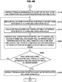
- Figure 6A and Figure 6B are flowcharts illustrating the method for setting a rolling mill according to the present embodiment.
- Figure 7 is an explanatory drawing showing procedures for roll position adjustment in the method for setting a rolling mill illustrated in Figure 6A and Figure 6B . Note that, in Figure 7 , a description of the distribution of loads acting between rolls is omitted, and a situation is described in which only inter-roll thrust forces that are the target appear as measurement values of the rolling direction forces.
- a roll gap between the upper work roll 1 and the lower work roll 2 is set in an open state, and then, with respect to the upper roll assembly and the lower roll assembly, operations are performed independently and respectively to adjust the positions of the work roll chocks that have an increase bending apparatus so that a rolling direction force acting on each work roll becomes zero, and an inter-roll cross between the rolls is made to fall within an allowable range.
- the upper work roll 1 and the lower work roll 2 are set in a kiss roll state, and thereafter the positions of the roll chocks of either one of the roll assemblies are adjusted so that rolling direction forces acting on the upper work roll 1 and the lower work roll 2 become zero.
- an inter-roll cross between the upper roll assembly and the lower roll assembly falls within an allowable range, and an inter-roll cross between all the rolls constituting the rolling mill is made to fall within an allowable range.
- the rolling direction position of the roll chocks of the reference roll is fixed as a reference position, and the positions in the rolling direction of the roll chocks of rolls other than the reference roll are moved to thereby adjust the positions of the roll chocks.
- the inter-roll cross control unit 23 causes the pressing-down device 50 to adjust the roll positions in the vertical direction so that the roll gap between the upper work roll 1 and the lower work roll 2 becomes an open state having a predetermined gap (S200).
- the pressing-down device 50 sets the increase bending forces in a balanced state, and sets the roll gap between the work rolls 1 and 2 in an open state.
- the term "balanced state” refers to a state in which a bending force of a degree that lifts up the self-weight of the work roll, roll chocks or the like is applied, and means that a load acting between the work roll and the backup roll is approximately zero.
- the inter-roll cross control unit 23 instructs the increase bending control unit 63 so as to apply a predetermined increase bending force from the balanced state to the work roll chocks 5 and 6 by means of the increase bending apparatuses 61a to 61d and 62a to 62d (S202).
- the increase bending control unit 63 controls the respective increase bending apparatuses 61a to 61d and 62a to 62d based on the instruction, to thereby apply a predetermined increase bending force to the work roll chocks 5 and 6.
- a predetermined load can be applied only between the work roll and backup roll on the upper side and lower side, respectively, without causing a load to act between the upper and lower work rolls. Note that, either step among step S200 and step S202 may be executed first.
- the inter-roll cross control unit 23 drives the driving electric motor 21 by means of the driving electric motor control unit 22 to cause the upper and lower work rolls 1 and 2 to rotate (S204). Subsequently, the rolling direction forces acting on the upper and lower work rolls are measured (S206), and a rolling direction force difference is calculated (S208).
- the rolling direction forces on the work side and the drive side of the upper work roll 1 are calculated by the upper work roll work-side rolling direction force calculation apparatus 26 and the upper work roll drive-side rolling direction force calculation apparatus (not illustrated in the drawings), respectively.
- the difference between the rolling direction force acting on the work side and the rolling direction force acting on the drive side of the upper work roll 1 is calculated by the upper work roll work side-drive side difference calculation apparatus 28, to thereby calculate a rolling direction force difference acting on the upper work roll 1.
- the rolling direction forces on the work side and the drive side of the lower work roll 2 are calculated by the lower work roll work-side rolling direction force calculation apparatus 27 and the lower work roll drive-side rolling direction force calculation apparatus (not illustrated in the drawings), respectively.
- the difference between the rolling direction force acting on the work side and the rolling direction force acting on the drive side of the lower work roll 2 is calculated by the lower work roll work side-drive side difference calculation apparatus 29, to thereby calculate a rolling direction force difference acting on the lower work roll 2.
- the rolling direction force differences acting on the upper and lower work rolls that are calculated are output to the inter-roll cross control unit 23.
- the inter-roll cross control unit 23 then controls the positions of the roll chocks of the rolls that have a bending apparatus, that is, the work roll chocks 5 and 6, so that the rolling direction force differences acting on the upper and lower work rolls become values that are within an allowable range (first adjustment in Figure 7 (P21, P22), S210).
- the first adjustment may be performed by performing position control of the backup roll of the roll assembly on the opposite side to the reference roll, that is, position control of the upper backup roll chocks 7a and 7b (P23 in Figure 7 ), so that a rolling direction force difference acting on the upper work roll of the upper roll assembly becomes a value within an allowable range.
- the positions of the lower work roll chocks 6 are adjusted (P24) in a similar manner to P22 in Figure 7 .
- step S212 with respect to the upper roll assembly and the lower roll assembly, when it is determined that rolling direction force differences acting on the work rolls or backup rolls are within an allowable range, position adjustment of the work roll chocks 5 and 6 ends.
- first adjustment performed in this manner, an inter-roll cross between the upper backup roll 3 and the upper work roll 1, and an inter-roll cross between the lower backup roll 4 and the lower work roll 2 are each adjusted to within an allowable range.
- the inter-roll cross control unit 23 adjusts an inter-roll cross between the upper roll assembly and the lower roll assembly, as illustrated on the lower side in Figure 7 .
- the inter-roll cross control unit 23 causes the pressing-down device 50 to adjust roll positions in the vertical direction so that the upper work roll 1 and the lower work roll 2 enter a predetermined kiss roll state (S214).
- the pressing-down device 50 applies a predetermined load to the rolls based on the instruction to thereby cause the work rolls 1 and 2 to come in contact and enter a kiss roll state.
- the inter-roll cross control unit 23 causes the driving electric motor 21 to drive by means of the driving electric motor control unit 22 to cause each roll to rotate, and rolling direction force differences acting on the upper work roll 1 and the lower work roll 2 are determined by measuring rolling direction forces by means of the rolling direction force measurement apparatuses 24a to 24d and 25a to 25d (S216), and calculating the rolling direction force differences based on the measured rolling direction forces (S218). It suffices to perform the processing in steps S216 and S218 in a similar manner to the processing in steps S206 and S208, and hence a description of the processing in steps S216 and S218 is omitted here.
- the calculated rolling direction force differences are output to the inter-roll cross control unit 23.
- the inter-roll cross control unit 23 controls the positions of the work roll chocks and the backup roll chocks of the upper roll assembly or the lower roll assembly simultaneously and in the same direction while maintaining the relative position between the roll chocks, so that rolling direction force differences acting on the upper work roll 1 and the lower work roll 2 become a value within an allowable range (S220).
- S220 an allowable range
- the positions of the upper work roll chocks 5a and 5b and the upper backup roll chocks 7a and 7b of the upper roll assembly are controlled so that an inter-roll cross with respect to the lower roll assembly falls within an allowable range (P25 in Figure 7 ).
- the inter-roll cross control unit 23 instructs the roll chock rolling direction force control unit 15 and the roll chock position control unit 16 so as to adjust the positions of the work roll chocks and the backup roll chocks on the opposite side to the reference roll assembly.
- the roll chock rolling direction force control unit 15 adjusts the positions of the work roll chocks and the backup roll chocks until rolling direction force differences acting on the upper work roll 1 and the lower work roll 2 fall within the allowable range (S222).
- the inter-roll cross of the upper roll assembly and the inter-roll cross of the lower roll assembly have already been adjusted. Therefore, position control of not only the work roll chocks but also the backup roll chocks is performed so that the backup rolls move simultaneously with and in the same direction as the work rolls while maintaining the relative positions between the roll chocks.
- step S222 when it is determined that the rolling direction force differences acting on the upper work roll 1 and the lower work roll 2 have entered the allowable range, the inter-roll cross between the upper backup roll 3, the upper work roll 1, the lower work roll 2 and the lower backup roll 4 is adjusted to within an allowable range.
- the inter-roll cross control unit 23 causes the pressing-down device 50 to perform adjustment so that the roll gap between the upper work roll 1 and the lower work roll 2 becomes a predetermined size (S224). Thereafter, rolling of a workpiece by the rolling mill is started.
- a rolling mill and a method for setting a rolling mill according to the second embodiment of the present invention have been described above. Note that, whilst an example in which only the upper and lower work rolls are provided with rolling direction force measurement apparatuses is described above, the present invention is not limited to this example. For example, it need scarcely be said that control can be similarly performed in a case where, in addition to providing the rolling direction force measurement apparatuses for the upper and lower work rolls, rolling direction force measurement apparatuses are provided for at least one of the upper backup roll and the lower backup roll also.
- position control of roll chocks is performed so that rolling direction force differences become zero or become a value within an allowable range in order to eliminate an inter-roll cross. This is based on the finding that the correlation described hereunder exists between rolling direction force differences and an inter-roll cross angle.
- Figure 8 to Figure 14 the relation between an inter-roll cross angle and various values will be described based on the results of experiments performed using a small rolling mill with a work roll diameter of 80 mm.
- Figure 8 is an explanatory drawing illustrating the arrangement of the work rolls 1 and 2 and the backup rolls 3 and 4 of the rolling mill that has been set in a kiss roll state.
- Figure 9 is an explanatory drawing showing the definition of an inter-roll cross angle.
- Figure 10 is a graph showing a relation between a backup roll cross angle and backup-roll rolling direction force differences in a kiss roll state.
- Figure 11 is an explanatory drawing illustrating the arrangement of the work rolls 1 and 2 and the backup rolls 3 and 4 of a rolling mill that has been set in a kiss roll state.
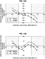
- Figure 12A is a graph illustrating a relation between a pair cross angle between a work roll and a backup roll, and upper and lower backup-roll rolling direction force differences in the kiss roll state.
- Figure 12B is a graph illustrating a relation between a pair cross angle between a work roll and a backup roll, and upper and lower work-roll rolling direction force differences in the kiss roll state.
- the object of the roll chock position control is ⁇ 0.1° or less, and by controlling the positions of the roll chocks so that a rolling direction force difference in that range becomes zero, the load distribution between rolls can be made uniform and inter-roll thrust forces can be suppressed.
- Figure 13 is an explanatory drawing illustrating the arrangement of the work rolls 1 and 2 and the backup rolls 3 and 4 of a rolling mill in which the roll gap is in an open state.
- Figure 14 is a graph illustrating one relation between a work roll cross angle and upper and lower work-roll rolling direction force differences in a state in which the roll gap is open.
- the roll gap between the upper work roll 1 and the lower work roll 2 was set in an open state, and a state was formed in which an increase bending force was applied by increase bending apparatuses to the work roll chocks. Then, changes in the work-roll rolling direction force differences when the cross angles of the upper work roll 1 and the lower work roll 2 were changed, respectively, were investigated.
- the increase bending force was set to 0.5 tonf per roll chock.
- a conventional method and the method of the present invention were compared with respect to fifth to seventh stands of a hot finish rolling mill having the configuration illustrated in Figure 2A , in relation to reduction leveling setting that takes into consideration the influence of inter-roll thrust forces generated due to an inter-roll cross.
- rolling direction force differences of the respective rolls are measured before rolling, and the roll chock positions of the respective rolls are controlled with respect to a reference roll so that the rolling direction force differences enter an allowable range based on appropriate logic, and by this means an inter-roll cross itself is eliminated, and left-right asymmetric deformation of a workpiece that occurs due to thrust forces caused by an inter-roll cross can be eliminated. Therefore, a metal plate material can be stably produced without zigzagging and camber or with extremely little zigzagging and camber.
- the upper and lower work rolls were set in a kiss roll state, rolling direction force differences acting on the upper and lower work rolls were calculated, and the positions of the roll chocks of the upper and lower work rolls and backup rolls were controlled so that the rolling direction force differences in question fell within an allowable range that was set in advance.
- Table 1 shows actual measurement values for the occurrence of camber with regard to a representative number of rolled workpieces, with respect to the present invention and the conventional method.
- Table 1 shows actual measurement values for the occurrence of camber with regard to a representative number of rolled workpieces, with respect to the present invention and the conventional method.
- the actual measurement values for camber per 1 m of a front end position of the workpieces when the value for a time that is immediately before backup roll replacement and also immediately before housing liner replacement is seen, it is found that in the case of the present invention the value is kept to a relatively small value of 0.12 mm/m.
- the actual measurement value for camber is large in comparison to the case of the present invention.
- rolling direction forces of the work rolls are measured before rolling, and the chock positions of the respective rolls are controlled with respect to a reference roll so that the rolling direction forces enter an allowable range based on appropriate logic, and by this means an inter-roll cross itself is eliminated, and left-right asymmetric deformation of a workpiece that occurs due to thrust forces caused by an inter-roll cross can be eliminated. Therefore, a metal plate material can be stably produced without zigzagging and camber or with extremely little zigzagging and camber.
- the present invention is also applicable to a rolling mill of four-high or more.
- a reference roll to serve as the reference for adjustment of the positions of roll chocks is set, and in such case, it suffices to set a roll located at the lowermost part or the uppermost part among the respective rolls arranged in the vertical direction, as the reference roll.
- intermediate rolls 41 and 42 are provided between the work roll 1 and the backup roll 3, and the work roll 2 and the backup roll 4, respectively.
- the upper intermediate roll 41 is supported by an upper intermediate roll chock 43a on the work side and an upper intermediate roll chock 43b on the drive side.
- the lower intermediate roll 42 is supported by an upper intermediate roll chock 44a on the work side and an upper intermediate roll chock 44b on the drive side.
- the upper intermediate roll chocks 43a and 43b and the lower intermediate roll chocks 44a and 44b are also sometimes referred to as simply "roll chocks".
- the rolling direction force measurement apparatuses 24a to 24d that measure rolling direction forces applied to the upper work roll 1 are provided, and in the lower work roll 2, the rolling direction force measurement apparatuses 25a to 25d that measure rolling direction forces applied to the lower work roll 2 are provided.
- the rolling direction force measurement apparatuses 34a to 34d that measure rolling direction forces applied to the upper backup roll 3 are provided, and in the lower backup roll 4, the rolling direction force measurement apparatuses 35a to 35d that measure rolling direction forces applied to the lower backup roll 4 are provided.
- rolling direction force measurement apparatuses 46a to 46d that measure rolling direction forces applied to the upper intermediate roll 41 are provided, and in the lower intermediate roll 42, rolling direction force measurement apparatuses 47a to 47d that measure rolling direction forces applied to the lower intermediate roll 42 are provided.
- the adjustment is performed in sequence as follows: a first adjustment is performed that performs a roll chock adjustment between the upper backup roll chocks 7a and 7b of the upper backup roll 3 and the upper intermediate roll chocks 43a and 43b of the upper intermediate roll 41; a second adjustment is performed that performs a roll chock adjustment between the upper intermediate roll chocks 43a and 43b of the upper intermediate roll 41 and the upper work roll chocks 5a and 5b of the upper work roll 1; a third adjustment is performed that performs a roll chock adjustment between the upper work roll chocks 5a and 5b of the upper work roll 1 and the lower work roll chocks 6a and 6b of the lower work roll 2; a fourth adjustment is performed that performs a roll chock adjustment between the lower work roll chocks 6a and 6b of the lower work roll 2 and the lower intermediate roll chocks 44a and 44b of the lower intermediate roll 42; and a fifth adjustment is performed that performs a first adjustment is performed that performs a roll chock adjustment between the upper backup
- rolling direction force measurement apparatuses are not provided in the upper backup roll 3 and the lower backup roll 4, and similarly to Figure 15 , the rolling direction force measurement apparatuses 24a to 24d, 25a to 25d, 46a to 46d and 47a to 47d are provided only in the upper work roll 1, the lower work roll 2, the upper intermediate roll 41 and the lower intermediate roll 42, respectively.
- the roll gap between the work rolls 1 and 2 is set in an open state, and for the upper roll assembly and the lower roll assembly, respectively, a first adjustment is performed to adjust the positions between the roll chocks 43a, 43b, 44a and 44b of the intermediate rolls 41 and 42 and the roll chocks 7a, 7b, 8a and 8b of the backup rolls 3 and 4.
- the roll gap between the work rolls 1 and 2 is maintained in an open state, and for the upper roll assembly and the lower roll assembly, respectively, a second adjustment is performed to adjust the positions between the roll chocks 43a, 43b, 44a and 44b of the intermediate rolls 41 and 42 and the roll chocks 5a, 5b, 6a and 6b of the work rolls 1 and 2.
- the work rolls 1 and 2 are set in a kiss roll state, and either one of the upper roll assembly and the lower roll assembly is decided on as the reference roll assembly. In the example in Figure 20, the lower roll assembly is adopted as the reference roll assembly.
- the roll chock positions of the reference roll assembly are fixed as reference positions, and a third adjustment is performed in which the positions of the roll chocks are adjusted between the upper roll assembly and the lower roll assembly by controlling the roll chocks 5a, 5b, 43a, 43b, 7a and 7b of the respective rolls 1, 41, 3 of the upper roll assembly simultaneously and in the same direction while maintaining the relative positions between the roll chocks 5a, 5b, 43a, 43b, 7a and 7b.
- bending apparatuses of the intermediate rolls 41 and 42 are used to apply loads between the intermediate rolls 41 and 42 and the backup rolls 3 and 4, and the bending apparatuses of the work rolls 1 and 2 are set at zero or in a balanced state.
- the present invention is also applicable to a six-high rolling mill, and not just a four-high rolling mill. Furthermore, the present invention is similarly applicable to rolling mills other than a four-high rolling mill and a six-high rolling mill, and for example the present invention can also be applied to an eight-high rolling mill or a five-high rolling mill.
Abstract
Description
- The present invention relates to a rolling mill that rolls a workpiece, and a method for setting the rolling mill.
- In a hot rolling process, for example, zigzagging of a steel plate occurs as a phenomenon that is the cause of rolling trouble. A thrust force that is generated at a minute cross (also referred to as "roll skew") between rolls of a rolling apparatus is one cause of zigzagging of a steel plate, and it is difficult to directly measure such a thrust force. Therefore, in the past it has been proposed to measure a thrust counterforce that is detected as a counterforce that is the total value of thrust forces generated between rolls or a roll skew angle, and identify the thrust force generated between rolls based on the thrust counterforce or the roll skew angle and perform zigzagging control of the steel plate.
- For example,
Patent Document 1 discloses a plate rolling method which measures a thrust counterforce in the axial direction of a roll and a load in a vertical direction, determines either one of, or both of, a reduction position zero point and deformation properties of the rolling mill, and sets the reduction position at the time of rolling execution and controls rolling. Further,Patent Document 2 discloses a zigzagging control method that calculates a thrust force generated at a roll based on an inter-roll minute cross angle (skew angle) that is measured using a distance sensor provided inside a rolling mill and, based on the thrust force, calculates a differential load component that is a cause of zigzagging based on a load measurement value in the vertical direction and performs reduction leveling control. In addition,Patent Document 3 discloses a cross-point correcting device which corrects a deviation in a point (cross point) at which the central axes of upper and lower rolls cross in the horizontal direction in a pair cross rolling mill. The apparatus includes an actuator that absorbs play that arises between a crosshead and roll chocks, and a detector that detects roll chock positions, and corrects a deviation in the cross point based on the roll chock positions. -
- Patent Document 1:
JP3499107B - Patent Document 2:
JP2014-4599A - Patent Document 3:
JP8-294713A - However, according to the technique disclosed in
Patent Document 1, although it is necessary to perform measurement of the thrust counterforce of rolls other than a backup roll at a time of reduction position zero point adjustment and during rolling, in the case of measuring thrust counterforces during rolling, in some cases characteristics such as the working point of the thrust counterforce change depending on changes in the rolling conditions such as the rolling load, and asymmetric deformation that accompanies the thrust force cannot be correctly identified. Therefore, there is the possibility that reduction leveling control cannot be accurately performed. - Further, according to the technique disclosed in
Patent Document 2, a roll skew angle is determined based on a distance in the horizontal direction of a roll that is measured by a distance sensor such as a vortex sensor. However, because a roll vibrates in the horizontal direction depending on the degree of machining precision such as the eccentricity or cylindricity of a roll body length portion, and chock positions in the horizontal direction fluctuate due to impact at the time of biting at the start of rolling and the like, it is difficult to accurately measure the horizontal displacement of a roll which is a factor that causes the generation of a thrust force. Furthermore, the coefficient of friction of a roll is constantly changing because the degree of roughness of a roll changes with time as the number of rolled workpieces increases. Therefore, calculation of a thrust force without identification of the coefficient of friction cannot be performed accurately based on only a roll skew angle measurement. - In addition, according to the technique disclosed in
Patent Document 3, an inter-roll cross angle arises due to relative crossing of rolls, and since there is also looseness in roll bearings and the like, even if position control of each roll chock position is individually performed in the rolling direction, deviations in the relative positional relation between the rolls themselves are not eliminated. Consequently, thrust forces that are generated due to inter-roll cross angles cannot be eliminated. - Further, as normal preparation operations before rolling, after replacing work rolls, the zero point of the reduction position in a kiss roll state is adjusted by an operator based on the values of vertical roll loads on the work side and the drive side. At such time, if an inter-roll thrust force is generated due to an inter-roll minute cross, in some cases a difference arises between the vertical roll load on the work side and the vertical roll load on the drive side, and the reduction position zero point adjustment cannot be correctly performed. However, it is not possible to reduce an inter-roll thrust force prior to reduction position zero point adjustment by employing a technique disclosed in any of the patent documents described above.
- The present invention has been made in view of the problems described above, and an objective of the present invention is to provide a novel and improved method for setting a rolling mill, and a rolling mill, before zero point of reduction position adjustment or before starting rolling, by reducing thrust forces generated between rolls and suppressing the occurrence of zigzagging and camber of a workpiece.
- To solve the problems described above, according to one aspect of the present invention there is provided a rolling mill of four-high or more that includes a plurality of rolls including at least a pair of work rolls and a pair of backup rolls supporting the work rolls, wherein any one roll among respective rolls arranged in a vertical direction is adopted as a reference roll, the rolling mill including: a measurement apparatus which measures at least rolling direction forces in a rolling direction which act on roll chocks on a work side and roll chocks on a drive side of each of the rolls other than the backup rolls; a pressing apparatus which, with respect to at least roll chocks of the rolls other than the reference roll, is provided on either one of an entrance side and an exit side in the rolling direction, the pressing apparatus pressing a workpiece in the rolling direction; a driving apparatus which, with respect to at least roll chocks of the rolls other than the reference roll, is provided so as to face the pressing apparatus in the rolling direction, the driving apparatus moving a workpiece in the rolling direction; and a position control unit that fixes a rolling direction position of roll chocks of the reference roll as a reference position, and based on a rolling direction force difference that is a difference between a rolling direction force on the work side and a rolling direction force on the drive side, drives the driving apparatus to control positions in the rolling direction of the roll chocks of the rolls other than the reference roll so that the rolling direction force difference of each of the rolls becomes a value within an allowable range.
- A roll located at a lowermost part or an uppermost part in the vertical direction among the plurality of rolls may be adopted as the reference roll.
- Further, the rolling mill may be provided a bending apparatus that imparts a bending force to the rolls, the position control unit sets a roll gap between the work rolls in an open state, and imparts a bending force by means of the bending apparatus to the roll chocks of the work rolls.
- The driving apparatus may be a hydraulic cylinder comprising a roll chock position detection apparatus.
- Further, to solve the problem described above, according to a different aspect of the present invention there is provided a method for setting a rolling mill, the rolling mill being a rolling mill of four-high or more that includes a plurality of rolls including at least a pair of work rolls and a pair of backup rolls supporting the work rolls, the method for setting a rolling mill being executed before reduction position zero point adjustment or before starting rolling, wherein any one roll among respective rolls arranged in a vertical direction is adopted as a reference roll, the method including: measuring at least rolling direction forces in a rolling direction that act on roll chocks on a work side and roll chocks on a drive side of the rolls other than the backup rolls, and fixing a rolling direction position of roll chocks of the reference roll as a reference position, and moving roll chocks of the rolls other than the reference roll in a rolling direction of a workpiece to adjust positions of the roll chocks so that a rolling direction force difference that is a difference between a rolling direction force measured on the work side and a rolling direction force measured on the drive side falls within an allowable range.
- A roll located at a lowermost part or an uppermost part in the vertical direction among the plurality of rolls may be adopted as the reference roll.
- In order from a roll assembly on an opposite side to the reference roll, the roll chocks of the rolls may be moved in the rolling direction of the workpiece to adjust the positions of the roll chocks so that the rolling direction force differences arising at the rolls that are adjacent fall within an allowable range, and at such time, the roll chocks of the rolls for which the position of the roll chocks is already adjusted may be controlled simultaneously and in a same direction while maintaining relative positions with respect to the roll chocks of the roll that is being adjusted.
- Further, in the rolling mill that is a four-high rolling mill, a plurality of rolls provided on an upper side in the vertical direction with respect to the workpiece are adopted as an upper roll assembly, and a plurality of rolls provided on a lower side in the vertical direction with respect to the workpiece are adopted as a lower roll assembly; the method may including performing: a first adjustment in which a roll gap between the work rolls is set in an open state, and with respect to each of the upper roll assembly and the lower roll assembly, positions of the roll chocks of the work roll and the roll chocks of the backup roll are adjusted, and after the first adjustment ends, a second adjustment in which the work rolls are set in a kiss roll state, and either one of the upper roll assembly and the lower roll assembly is adopted as a reference roll assembly, and positions of the roll chocks of each roll of the other roll assembly are adjusted by controlling the roll chocks simultaneously and in a same direction while maintaining relative positions between the roll chocks; and in the first adjustment, with respect to each of the upper roll assembly and the lower roll assembly, in a state in which a bending force is applied to the roll chocks of the work rolls having a bending apparatus, the roll chocks of the work roll on the reference roll side and either one of the roll chocks of the work roll and the roll chocks of the backup roll of the roll assembly on the opposite side to the reference roll are moved in the rolling direction of the workpiece to adjust positions of the roll chocks so that the rolling direction force difference measured falls within an allowable range.
- Further, in the rolling mill that is a six-high rolling mill comprising intermediate rolls between the work rolls and the backup rolls, respectively, a plurality of rolls provided on an upper side in the vertical direction with respect to the workpiece are adopted as an upper roll assembly, and a plurality of rolls provided on a lower side in the vertical direction with respect to the workpiece are adopted as a lower roll assembly; the method may including performing: a first adjustment in which a roll gap between the work rolls is set in an open state, and with respect to each of the upper roll assembly and the lower roll assembly, positions of the roll chocks of the intermediate roll and the roll chocks of the backup roll are adjusted, after the first adjustment ends, a second adjustment in which the roll gap between the work rolls is maintained in an open state, and with respect to each of the upper roll assembly and the lower roll assembly, positions of the roll chocks of the intermediate roll and the roll chocks of the work roll are adjusted, and after the second adjustment ends, a third adjustment in which the work rolls are set in a kiss roll state, either one of the upper roll assembly and the lower roll assembly is adopted as a reference roll assembly, and positions of the roll chocks of each roll of the other roll assembly are adjusted by controlling the roll chocks simultaneously and in a same direction while maintaining relative positions between the roll chocks; wherein, the first adjustment and the second adjustment are performed in a state in which a bending force is applied to the roll chocks of the intermediate rolls and the roll chocks of the work rolls that have a bending apparatus; in the first adjustment, with respect to each of the upper roll assembly and the lower roll assembly, the roll chocks of the intermediate roll on the reference roll side and either one of the roll chocks of the intermediate roll and the roll chocks of the backup roll of the roll assembly on the opposite side to the reference roll are moved in the rolling direction of the workpiece to adjust positions of the roll chocks so that the rolling direction force differences measured fall within an allowable range; and in the second adjustment, with respect to each of the upper roll assembly and the lower roll assembly, the roll chocks of the work roll on the reference roll side and either one of the roll chocks of the work roll and the roll chocks of the intermediate roll of the roll assembly on the opposite side to the reference roll are moved in the rolling direction of the workpiece to adjust positions of the roll chocks so that the rolling direction force differences measured fall within an allowable range, and in a case of moving the roll chocks of the intermediate roll of the roll assembly on the opposite side to the reference roll, the roll chocks of the intermediate roll and the roll chocks of the backup roll that is adjacent to the intermediate roll are controlled simultaneously and in a same direction while maintaining relative positions between the roll chocks of the intermediate roll and the roll chocks of the backup roll.
- As described above, according to the present invention, thrust forces generated between rolls can be reduced and the occurrence of zigzagging and camber of a workpiece can be suppressed.
-
- [
Figure 1] Figure 1 is a multiple view drawing including a schematic side view and a schematic front view of a rolling mill for describing a thrust force and a thrust counterforce which are generated between rolls of a rolling mill during rolling. - [
Figure 2A] Figure 2A is an explanatory drawing illustrating the configuration of a rolling mill according to a first embodiment of the present invention, and an apparatus for controlling the rolling mill. - [
Figure 2B] Figure 2B is an explanatory drawing illustrating rolling direction force measurement apparatuses that are arranged on an entrance side and an exit side of the rolling mill illustrated inFigure 2A . - [
Figure 3A] Figure 3A is a flowchart describing a method for setting a rolling mill according to the first embodiment, which illustrates an example of a case of performing position adjustment from a roll on an opposite side to a reference roll. - [
Figure 3B] Figure 3B is a flowchart describing a method for setting a rolling mill according to the first embodiment, which illustrates an example of a case of performing position adjustment from a roll on an opposite side to a reference roll. - [
Figure 3C] Figure 3C is a flowchart describing a method for setting a rolling mill according to the first embodiment, which illustrates an example of a case of performing position adjustment from a roll on an opposite side to a reference roll. - [
Figure 4] Figure 4 is an explanatory drawing showing procedures for roll position adjustment in the method for setting a rolling mill illustrated inFigure 3A to Figure 3C . - [
Figure 5] Figure 5 is an explanatory drawing illustrating the configuration of a rolling mill according to a second embodiment of the present invention, and an apparatus for controlling the rolling mill. - [
Figure 6A] Figure 6A is a flowchart describing the method for setting a rolling mill according to the second embodiment. - [
Figure 6B] Figure 6B is a flowchart describing the method for setting a rolling mill according to the second embodiment. - [
Figure 7] Figure 7 is an explanatory drawing showing procedures for roll position adjustment in the method for setting a rolling mill illustrated inFigure 6A andFigure 6B . - [
Figure 8] Figure 8 is an explanatory drawing illustrating the arrangement of work rolls and backup rolls of a rolling mill set in a kiss roll state, that shows a state without a pair cross. - [
Figure 9] Figure 9 is an explanatory drawing showing the definition of an inter-roll cross angle. - [
Figure 10] Figure 10 is a graph showing a relation between a backup roll cross angle and a backup-roll rolling direction force in the kiss roll state illustrated inFigure 9 . - [
Figure 11] Figure 11 is an explanatory drawing illustrating the arrangement of work rolls and backup rolls of a rolling mill set in a kiss roll state, that shows a state with a pair cross. - [
Figure 12A] Figure 12A is a graph illustrating a relation between a pair cross angle between a work roll and a backup roll, and upper and lower backup-roll rolling direction force differences in the kiss roll state illustrated inFigure 11 . - [
Figure 12B] Figure 12B is a graph illustrating a relation between a pair cross angle between a work roll and a backup roll, and upper and lower work-roll rolling direction force differences in the kiss roll state illustrated inFigure 11 . - [
Figure 13] Figure 13 is an explanatory drawing illustrating the arrangement of work rolls and backup rolls of a rolling mill in which a roll gap is in an open state. - [
Figure 14] Figure 14 is a graph illustrating a relation between a backup roll cross angle and a work-roll rolling direction force, in a state in which a roll gap is open. - [
Figure 15] Figure 15 is an explanatory drawing illustrating procedures for roll position adjustment in a case where the method for setting a rolling mill illustrated inFigure 4 is applied to a six-high rolling mill. - [
Figure 16] Figure 16 is an explanatory drawing illustrating procedures for roll position adjustment in a case where the method for setting a rolling mill illustrated inFigure 7 is applied to a six-high rolling mill. - Hereunder, preferred embodiments of the present invention are described in detail while referring to the accompanying drawings. Note that, in the present specification and the accompanying drawings, constituent elements having substantially the same functional configuration are denoted by the same reference characters and a duplicate description thereof is omitted.
- An objective of a rolling mill as well as a method for setting the rolling mill according to the embodiments of the present invention is to eliminate thrust forces generated between rolls, and enable the stable production of products without zigzagging and camber or with extremely little zigzagging and camber. In
Figure 1 , a schematic side view and a schematic front view of a rolling mill are illustrated for describing a thrust force and a thrust counterforce which are generated between rolls of a rolling mill during rolling of a workpiece S. Hereunder, as illustrated inFigure 1 , the work side in the axial direction of rolls is represented by "WS", and the drive side is represented by "DS". - The rolling mill illustrated in
Figure 1 has a pair of work rolls consisting of anupper work roll 1 and alower work roll 2, and a pair of backup rolls consisting of anupper backup roll 3 that supports theupper work roll 1 in the vertical direction (Z direction) and alower backup roll 4 that supports thelower work roll 2 in the vertical direction. The work side of theupper work roll 1 is supported by an upper work roll chock 5a, and the drive side of theupper work roll 1 is supported by an upper work roll chock 5b. The work side of thelower work roll 2 is supported by a lower work roll chock 6a, and the drive side of thelower work roll 2 is supported by a lower work roll chock 6b. Similarly, the work side of theupper backup roll 3 is supported by an upper backup roll chock 7a, and the drive side of theupper backup roll 3 is supported by an upper backup roll chock 7b. The work side of thelower backup roll 4 is supported by a lower backup roll chock 8a, and the drive side of thelower backup roll 4 is supported by a lower backup roll chock 8b. - The
upper work roll 1, thelower work roll 2, theupper backup roll 3 and thelower backup roll 4 are arranged in a manner in which the axial directions of the respective rolls are parallel, so as to be orthogonal with the conveyance direction of the workpiece S. However, if a roll rotates slightly about an axis (Z-axis) that is parallel with the vertical direction and a deviation arises between the axial directions of theupper work roll 1 and theupper backup roll 3, or a deviation arises between the axial directions of thelower work roll 2 and thelower backup roll 4, a thrust force that acts in the axial direction of the rolls arises between the work roll and the backup roll. An inter-roll thrust force gives an extra moment to the rolls, and causes asymmetric roll deformation to occur due to the aforementioned moment. The asymmetric roll deformation is a factor that causes the rolling to enter an unstable state, and for example gives rise to zigzagging or camber. The inter-roll thrust force is generated as a result of an inter-roll cross angle arising due to the occurrence of a deviation between the axial directions of a work roll and a backup roll. For example, let us assume that an inter-roll cross angle arises between thelower work roll 2 and thelower backup roll 4. At such time, a thrust force is generated between thelower work roll 2 and thelower backup roll 4, and as a result, a moment occurs at thelower backup roll 4, and the load distribution between the rolls changes to balance with the moment, and thus an asymmetric roll deformation occurs. Zigzagging or camber or the like is caused by the asymmetric roll deformation, and the rolling becomes unstable. - As described above, an objective of the present invention is, during rolling of a workpiece by a rolling mill, to adjust roll chock positions of each roll so that inter-roll thrust forces generated between rolls are eliminated, based on a left-right difference in rolling direction forces before reduction position zero point adjustment or before the start of rolling, and thereby enable the stable production of products without zigzagging and camber or with extremely little zigzagging and camber.
- The configuration of a rolling mill according to a first embodiment of the present invention and an apparatus for controlling the rolling mill, as well as a method for setting a rolling mill will be described based on
Figure 2A to Figure 4 . In the first embodiment, before reduction position zero point adjustment or before the start of rolling, the positions of roll chocks are adjusted so as to make an inter-roll cross angle between a backup roll serving as a reference and other rolls zero, to thereby realize rolling in which thrust forces do not arise. - First, the rolling mill according to the present embodiment and an apparatus for controlling the rolling mill will be described based on
Figure 2A andFigure 2B .Figure 2A is an explanatory drawing illustrating the configuration of the rolling mill according to the present embodiment, and an apparatus for controlling the rolling mill.Figure 2B is an explanatory drawing illustrating rolling direction force measurement apparatuses that are arranged on an entrance side and an exit side of the rolling mill illustrated inFigure 2A . Note that, it is assumed that the rolling mill illustrated inFigure 2A is shown in a state as seen from the work side in the axial direction of the rolls. Further, inFigure 2A , a configuration in a case where the lower backup roll is adopted as the reference roll is illustrated. Note that, the reference roll is preferably a roll for which the area of contact between the chocks and the housing is large, and which is located at the lowermost part or the uppermost part, where the position is stable. - The rolling mill illustrated in
Figure 2A is a four-high rolling mill having a pair of work rolls 1 and 2 and a pair of backup rolls 3 and 4 that support the pair of work rolls 1 and 2. In the four-high rolling mill, theupper work roll 1, thelower work roll 2, theupper backup roll 3 and thelower backup roll 4 are a plurality of rolls which are arranged in the vertical direction. Theupper work roll 1 and thelower work roll 2 are rotationally driven by a drivingelectric motor 21. As illustrated inFigure 2B , theupper work roll 1 is supported by upperwork roll chocks lower work roll 2 is supported by lowerwork roll chocks Figure 2A , the upper work roll chock 5b and the lower work roll chock 6b that are illustrated inFigure 2B are provided on the drive side that is on the side facing away from the viewer inFigure 2A . As illustrated inFigure 2B , the upperwork roll chocks work roll chocks force measurement apparatuses 24a to 24d, 25a to 25d, 34a to 34d and 35a to 35d which detect a load in the rolling direction, respectively. The rolling directionforce measurement apparatuses force measurement apparatus backup roll chocks 8 are sometimes referred to as simply "roll chocks". Further, the rolling directionforce measurement apparatuses 24a to 24d, 25a to 25d, 34a to 34d and 35a to 35d are likewise sometimes referred to as simply "measurement apparatuses". - The
upper backup roll 3 is supported by the upper backup roll chocks 7a and 7b, and thelower backup roll 4 is supported by the lower backup roll chocks 8a and 8b. Although only the upper backup roll chock 7a and the lower backup roll chock 8a on the work side are illustrated inFigure 2A , the upper backup roll chock 7b and the lower backup roll chock 8b that are illustrated inFigure 2B are provided on the drive side that is on the side facing away from the viewer inFigure 2A . The upperwork roll chocks work roll chocks housing 30. - The upper
work roll chocks pressing apparatus 9 which is provided on the entrance side in the rolling direction and which presses the upperwork roll chocks position detection function 11 which is provided on the exit side in the rolling direction and which detects the position in the rolling direction and drives the upperwork roll chocks force measurement apparatuses 24a to 24d which measure rolling direction forces applied to theupper work roll 1 are provided in theupper work roll 1. - Similarly, the lower
work roll chocks apparatus 10 which is provided on the entrance side in the rolling direction and which presses the lowerwork roll chocks position detection function 12 which is provided on the exit side in the rolling direction and which detects the position in the rolling direction and drives the lowerwork roll chocks position detection function 11, the driving apparatus with lower work roll chockposition detection function 12, a drive mechanism of the upper work roll chockpressing apparatus 9 and a drive mechanism of the lower work roll chock pressingapparatus 10. Note that, whilst the upper and lower driving apparatuses with work roll chockposition detection function pressing apparatuses Figure 2A , these apparatuses are also similarly provided on the side facing away from the viewer (drive side) inFigure 2A . - The upper backup roll chocks 7a and 7b are provided with an upper backup roll chock pressing
apparatus 13 which is provided on the exit side in the rolling direction and which presses the upper backup roll chocks 7a and 7b in the rolling direction, and a driving apparatus with upper backup roll chockposition detection function 14 which is provided on the entrance side in the rolling direction and which detects the position in the rolling direction and drives the upper backup roll chocks 7a and 7b in the rolling direction. For example, a hydraulic cylinder is used as the driving apparatus with upper backup roll chockposition detection function 14 and the drive mechanism of the upper backup roll chock pressingapparatus 13. Note that, whilst the driving apparatus with upper backup roll chockposition detection function 14 and the upper backup roll chock pressingapparatus 13 are shown only on the work side inFigure 2A , these apparatuses are also similarly provided on the side facing away from the viewer (drive side) inFigure 2A . - On the other hand, with respect to the lower backup roll chocks 8a and 8b, since the
lower backup roll 4 is adopted as the reference roll in the present embodiment, the lower backup roll chocks 8a and 8b serve as reference backup roll chocks. Accordingly, since the lower backup roll chocks 8a and 8b are not driven to perform position adjustment, the lower backup roll chocks 8a and 8b do not necessarily need to be equipped with a driving apparatus and a position detection apparatus as in the case of the upper backup roll chocks 7a and 7b. However, a configuration may be adopted in which, for example, a lower backup roll chock pressingapparatus 40 or the like is provided on the entrance side or the exit side in the rolling direction to suppress the occurrence of looseness of the lower backup roll chocks 8a and 8b so that the position of the reference backup roll chocks that serve as the reference for position adjustment does not change. Note that, whilst the lower backup roll chock pressingapparatus 40 is shown only on the work side inFigure 2A , this apparatus is also similarly provided on the side facing away from the viewer (drive side) inFigure 2A . - The upper work roll chock
pressing apparatus 9, the lower work roll chock pressingapparatus 10, the upper backup roll chock pressingapparatus 13 and the lower backup roll chock pressingapparatus 40 are provided on either one of the entrance side and the exit side in the rolling direction of the workpiece, and are pressing apparatuses that press the roll chocks in the rolling direction, and are sometimes referred to as simply "pressing apparatuses". It suffices that the pressing apparatuses are provided with respect to at least the roll chocks of the rolls other than the reference roll. Further, the driving apparatus with upper work roll chockposition detection function 11, the driving apparatus with lower work roll chockposition detection function 12 and the driving apparatus with upper backup roll chockposition detection function 14 are provided so as to face the pressing apparatuses in the rolling direction, and are driving apparatuses that move the roll chocks in the rolling direction, and are sometimes referred to as simply "driving apparatuses". It suffices that the driving apparatuses also are provided with respect to at least the roll chocks of the rolls other than the reference roll. - As apparatuses for controlling the rolling mill, for example, as illustrated in
Figure 2A , the configuration includes a roll chock rolling directionforce control unit 15, a roll chockposition control unit 16, a driving electricmotor control unit 22 and an inter-rollcross control unit 23. - The roll chock rolling direction
force control unit 15 controls a pressing force in the rolling direction of the upper work roll chockpressing apparatus 9, the lower work roll chock pressingapparatus 10, the upper backup roll chock pressingapparatus 13 and the lower backup roll chock pressingapparatus 40. Based on a control instruction of the inter-rollcross control unit 23 that is described later, the roll chock rolling directionforce control unit 15 drives the upper work roll chockpressing apparatus 9, the lower work roll chock pressingapparatus 10, and the upper backup roll chock pressingapparatus 13 that are control objects with respect to chock positions to thereby produce a state in which it is possible to control the chock positions by application of a predetermined pressing force. - The roll chock
position control unit 16 performs drive control of the driving apparatus with upper work roll chockposition detection function 11, the driving apparatus with lower work roll chockposition detection function 12 and the driving apparatus with upper backup roll chockposition detection function 14. The roll chockposition control unit 16 is also referred to as simply "position control unit". Based on a control instruction of the inter-rollcross control unit 23, the roll chockposition control unit 16 drives the driving apparatus with upper work roll chockposition detection function 11, the driving apparatus with lower work roll chockposition detection function 12 and the driving apparatus with upper backup roll chockposition detection function 14 so that a rolling direction force difference that is a difference between a rolling direction force acting on the roll chocks on the work side and a rolling direction force acting on the roll chocks on the drive side is within a predetermined range. The driving apparatuses with position detection functions 11, 12 and 14 are disposed on both the work side and the drive side, and with respect to the positions in the rolling direction on the work side and the drive side, by controlling the driving apparatuses with position detection functions 11, 12 and 14 so that the positions change by the same amount in opposite directions on the work side and the drive side, can change a roll cross angle only, without changing the average rolling direction position of the work side and drive side. - The driving electric
motor control unit 22 controls the drivingelectric motor 21 that rotationally drives theupper work roll 1 and thelower work roll 2. The driving electricmotor control unit 22 according to the present embodiment controls driving of theupper work roll 1 or thelower work roll 2 based on an instruction from the inter-rollcross control unit 23. - The inter-roll
cross control unit 23 controls the position of each of theupper work roll 1, thelower work roll 2, theupper backup roll 3 and thelower backup roll 4 constituting the rolling mill by adjusting the positions of the roll chocks, so that an inter-roll cross angle is zero. In the rolling mill according to the present embodiment, the positions of the roll chocks are adjusted by making a difference (rolling direction force difference) between a rolling direction force acting on roll chocks on the work side and a rolling direction force acting on roll chocks on the drive side become a value within a predetermined range. - With regard to the upper work roll chock 5a on the work side, a difference between a rolling direction force measured by the entrance-side rolling direction
force measurement apparatus 24a and a rolling direction force measured by the exit-side rolling directionforce measurement apparatus 24b on the work side is calculated by an upper work roll work-side rolling direction forcecalculation apparatus 26, and is taken as the rolling direction force on the work side of theupper work roll 1. Similarly, a difference between a rolling direction force measured by the entrance-side rolling directionforce measurement apparatus 24c and a rolling direction force measured by the exit-side rolling directionforce measurement apparatus 24d on the drive side is calculated by an upper work roll drive-side rolling direction force calculation apparatus (not illustrated in the drawings), and is taken as the rolling direction force on the drive side of theupper work roll 1. Further, a difference between a calculated value f11 of the rolling direction force on the work side and a calculated value f12 of the rolling direction force on the drive side of theupper work roll 1 is calculated by an upper work roll work side-drive sidedifference calculation apparatus 28 to thereby calculate a rolling direction force difference acting on the upperwork roll chocks - With regard to the lower work roll chock 6a on the work side, a difference between a rolling direction force measured by the entrance-side rolling direction
force measurement apparatus 25a and a rolling direction force measured by the exit-side rolling directionforce measurement apparatus 25b on the work side is calculated by a lower work roll work-side rolling direction forcecalculation apparatus 27, and is taken as the rolling direction force on the work side of thelower work roll 2. Similarly, a difference between a rolling direction force measured by the entrance-side rolling directionforce measurement apparatus 25c and a rolling direction force measured by the exit-side rolling directionforce measurement apparatus 25d on the drive side is calculated by a lower work roll drive-side rolling direction force calculation apparatus (not illustrated in the drawings), and is taken as the rolling direction force on the drive side of thelower work roll 2. Further, a difference between a calculated value f21 of the rolling direction force on the work side and a calculated value f22 of the rolling direction force on the drive side of thelower work roll 2 is calculated by a lower work roll work side-drive sidedifference calculation apparatus 29 to thereby calculate a rolling direction force difference acting on the lowerwork roll chocks - With regard to the upper backup roll chock 7a on the work side, a difference between a rolling direction force measured by the entrance-side rolling direction
force measurement apparatus 34a and a rolling direction force measured by the exit-side rolling directionforce measurement apparatus 34b on the work side is calculated by an upper backup roll work-side rolling direction forcecalculation apparatus 36, and is taken as the rolling direction force on the work side of theupper backup roll 3. Similarly, a difference between a rolling direction force measured by the entrance-side rolling directionforce measurement apparatus 34c and a rolling direction force measured by the exit-side rolling directionforce measurement apparatus 34d on the drive side is calculated by an upper backup roll drive-side rolling direction force calculation apparatus (not illustrated in the drawings), and is taken as the rolling direction force on the drive side of theupper backup roll 3. Further, a difference between a calculated value f31 of the rolling direction force on the work side and a calculated value f32 of the rolling direction force on the drive side of theupper backup roll 3 is calculated by an upper backup roll work side-drive sidedifference calculation apparatus 38 to thereby calculate a rolling direction force difference acting on the upper backup roll chocks 7a and 7b. - With regard to the lower backup roll chock 8a on the work side, a difference between a rolling direction force measured by the entrance-side rolling direction
force measurement apparatus 35a and a rolling direction force measured by the exit-side rolling directionforce measurement apparatus 35b on the work side is calculated by a lower backup roll work-side rolling direction forcecalculation apparatus 37, and is taken as the rolling direction force on the work side of thelower backup roll 4. Similarly, a difference between a rolling direction force measured by the entrance-side rolling directionforce measurement apparatus 35c and a rolling direction force measured by the exit-side rolling directionforce measurement apparatus 35d on the drive side is calculated by a lower backup roll drive-side rolling direction force calculation apparatus (not illustrated in the drawings), and is taken as the rolling direction force on the drive side of thelower backup roll 4. Further, a difference between a calculated value f41 of the rolling direction force on the work side and a calculated value f42 of the rolling direction force on the drive side of thelower backup roll 4 is calculated by a lower backup roll work side-drive sidedifference calculation apparatus 39 to thereby calculate a rolling direction force difference acting on the lower backup roll chocks 8a and 8b. - Based on the rolling direction force differences calculated by the upper work roll work side-drive side
difference calculation apparatus 28, the lower work roll work side-drive sidedifference calculation apparatus 29, the upper backup roll work side-drive sidedifference calculation apparatus 38 and the lower backup roll work side-drive sidedifference calculation apparatus 39, the inter-rollcross control unit 23 issues control instructions to the roll chock rolling directionforce control unit 15, the roll chockposition control unit 16 and the driving electricmotor control unit 22 so that the rolling direction force differences become values that are not more than an allowable range, so that crosses that occurred between the rolls are eliminated. Note that the details of the method for setting the rolling mill are described later. - Although an example has been described above in which, with respect to the work roll chocks 5 and 6, the driving apparatuses with position detection functions 11 and 12 are arranged on the exit side and the
pressing apparatuses position detection function 14 is arranged on the entrance side and thepressing apparatus 13 is arranged on the exit side of the rolling mill, the present invention is not limited to this example. For example, the arrangement of these apparatuses with respect to the entrance side and the exit side of the rolling mill may be the reverse of the arrangement in the above example, or these apparatuses may be installed in the same direction with respect to the work rolls and the backup rolls. In addition, with regard to the driving apparatuses with position detection functions 11, 12 and 14, whilst an example has been described in which these apparatuses are provided on both the work side and the drive side and the respective apparatuses are subjected to position control, the present invention is not limited to this example. These apparatuses may be provided on only one side among the work side and the drive side, or alternatively it is possible to adopt a configuration so that only the apparatuses provided on one side are actuated and to control a roll cross angle by performing position control by taking the opposite side thereto as the support point of rotation, and it need scarcely be said that the same effect of reducing an inter-roll cross is obtained. - Further, whilst an example has been described above in which all of the rolls are provided with a rolling direction force measurement apparatus, the present invention is not limited to this example. For example, it is possible to perform similar control even in a case where only the upper work roll rolling direction
force measurement apparatuses 24a to 24d and the lower work roll rolling directionforce measurement apparatuses 25a to 25d are provided, or a case where the upper backup roll rolling directionforce measurement apparatuses 34a to 34d or the lower backup roll rolling directionforce measurement apparatuses 35a to 35d are also provided in addition to theaforementioned measurement apparatuses 24a to 24d and 25a to 25d. The control procedures for such cases are described later. - Furthermore, whilst an example has been described above in which rolling direction force measurement apparatuses are provided on both the entrance side and the exit side, the present invention is not limited to this example. For example, in a case where work rolls are offset in the rolling direction on one side among the entrance side and the exit side of the rolling mill, or a case where the force of the roll chock pressing apparatuses is large and rolling direction forces act only in the direction of one side among the entrance side and the exit side of the rolling mill, control can be similarly performed by providing the rolling direction force measurement apparatuses on one side among the entrance side and the exit side that is the side in the direction in which the rolling direction forces act, and calculating the differences between the work side and the drive side of these rolling direction forces that act on one side.
- In addition, whilst an example has been described above in which a driving apparatus with a position detection function is provided on the work side and the drive side for all of the rolls except the reference roll, the present invention is not limited to this example. For example, all of the rolls may be provided with a driving apparatus with a position detection function, and the reference roll may be changed according to the situation, and control may be performed based on the changed reference roll. Alternatively, a driving apparatus with a position detection function may be provided on either one side among the work side and the drive side, with the opposite side being taken as a pivot, and the inter-roll cross angle may be similarly controlled by controlling only the roll chock positions on one side.
- The method for setting a rolling mill according to the present embodiment will now be described based on
Figure 3A to Figure 4 . The method for setting a rolling mill according to the present embodiment is a method which is executed before reduction position zero point adjustment or before the start of rolling, and which adjusts the positions of roll chocks from a roll on an opposite side to a reference roll, and in which rolling direction force differences of all the rolls are measured in order to perform position adjustment of the roll chocks.Figure 3A to Figure 3C are flowcharts for describing the method for setting a rolling mill according to the present embodiment, and show an example of a case of performing position adjustment from a roll on the opposite side to the reference roll.Figure 4 is an explanatory drawing showing procedures for roll position adjustment in the method for setting a rolling mill according to the present embodiment. Note that, inFigure 4 , a description of the distribution of loads acting between rolls is omitted, and a situation is described in which only inter-roll thrust forces that are the target appear as measurement values of the rolling direction forces. - Although in the following description the
lower backup roll 4 is described as the reference roll, in the present embodiment it suffices to set either the roll at the uppermost part or the roll at the lowermost part in the vertical direction as the reference roll, and in some cases theupper backup roll 3 serves as the reference roll. In this case also, by similar procedures as described hereunder, it suffices to perform position adjustment of rolls in order from the roll assembly on the opposite side to the reference roll in a manner such that, first, position adjustment is performed between the roll (lower backup roll 4) that is furthest from the reference roll (upper backup roll 3) and the roll (lower work roll 2) that is second furthest from the reference roll, followed by position adjustment between the aforementioned two rolls and the roll (upper work roll 1) that is third furthest from the reference roll, and finally position adjustment between the aforementioned three rolls and the reference roll. - As shown in
Figure 3A , first, the inter-rollcross control unit 23 outputs an instruction to a pressing-down device 50 to adjust roll positions in the vertical direction so that theupper work roll 1 and thelower work roll 2 enter a predetermined kiss roll state (S100). The pressing-down device 50 applies a predetermined load to the rolls based on the instruction to thereby set the work rolls 1 and 2 in a kiss roll state. Further, the inter-rollcross control unit 23 instructs the driving electricmotor control unit 22 so as to cause theupper work roll 1 and thelower work roll 2 to rotate at a predetermined rotational speed (S102). - Next, position adjustment of the respective rolls is performed in a stepwise manner. At such time, the rolling direction position of the roll chocks of the reference roll is fixed as a reference position, and the positions in the rolling direction of the roll chocks of the rolls other than the reference roll are moved to thereby adjust the positions of the roll chocks.
- In the first adjustment, as illustrated in
Figure 4 , the positions of the upper backup roll chocks 7a and 7b are adjusted so that a rolling direction force difference acting on theupper backup roll 3 that is in the roll assembly on the opposite side to thelower backup roll 4 that is the reference roll becomes zero (P11). Therefore, first, the inter-rollcross control unit 23 drives the drivingelectric motor 21 by means of the driving electricmotor control unit 22 to cause the respective rolls to rotate. Next, rolling direction forces acting on theupper backup roll 3 are measured by the rolling directionforce measurement apparatuses 34a to 34d (S104). Upon the rolling direction forces on the entrance side and the exit side of the upper backup roll chocks 7a and 7b that are on the work side being measured by the rolling directionforce measurement apparatuses upper backup roll 3 is calculated by the upper backup roll work-side rolling direction forcecalculation apparatus 36. Further, upon the rolling direction forces on the entrance side and the exit side of the upper backup roll chocks 7a and 7b that are on the drive side being measured by the rolling directionforce measurement apparatuses upper backup roll 3 is calculated by the upper backup roll drive-side rolling direction force calculation apparatus (not illustrated in the drawings). Subsequently, a rolling direction force difference acting on theupper backup roll 3 that is the difference between the rolling direction force on the work side and the rolling direction force on the drive side of theupper backup roll 3 is calculated by the upper backup roll work side-drive side difference calculation apparatus 38 (S106). The rolling direction force difference acting on theupper backup roll 3 is output to the inter-rollcross control unit 23. - Next, the inter-roll
cross control unit 23 controls the positions of the upper backup roll chocks 7a and 7b so that the measured rolling direction force difference acting on theupper backup roll 3 falls within an allowable range (S108). The upper and lower limit values with respect to the values in an allowable range of the rolling direction force difference may be determined after performing roll deformation analysis under kiss roll conditions, and converting an asymmetric deformation amount into a reduction leveling amount. For example, it suffices to calculate upper and lower limit values within an allowable range of a roll cross angle based on an existing rolling model in which a limit value of camber that is required for a product or a limit value of camber at which tail crash occurs is taken as a reference. - The inter-roll
cross control unit 23 instructs the roll chock rolling directionforce control unit 15 and the roll chockposition control unit 16 so as to adjust the positions of the upper backup roll chocks 7a and 7b so that the rolling direction force difference falls within the allowable range. While detecting the positions of the upper backup roll chocks 7a and 7b by means of the roll chockposition control unit 16, the positions of the upper backup roll chocks 7a and 7b are adjusted by the roll chock rolling directionforce control unit 15 until the rolling direction force difference acting on theupper backup roll 3 falls within the allowable range (S110). - Subsequently, in step S110, when it is determined that the rolling direction force difference acting on the
upper backup roll 3 is within the allowable range, position adjustment of the upper backup roll chocks 7a and 7b ends. By performing the first adjustment, an inter-roll cross between theupper backup roll 3 and theupper work roll 1 is adjusted to within an allowable range. - Next, in the second adjustment, as illustrated in
Figure 4 , the rolling mill is adjusted so that a rolling direction force difference acting on theupper work roll 1 that is in the roll assembly on the opposite side to thelower backup roll 4 that is the reference roll becomes zero (P12). As shown inFigure 3B , in a state in which the respective rolls are being rotated by the drivingelectric motor 21, the inter-rollcross control unit 23 measures rolling direction forces acting on theupper work roll 1 by means of the rolling directionforce measurement apparatuses 24a to 24d (S112). Upon the rolling direction forces on the entrance side and the exit side of the upperwork roll chocks force measurement apparatuses upper work roll 1 is calculated by the upper work roll work-side rolling direction forcecalculation apparatus 26. Further, upon the rolling direction forces on the entrance side and the exit side of the upperwork roll chocks force measurement apparatuses upper work roll 1 is calculated by the upper work roll drive-side rolling direction force calculation apparatus (not illustrated in the drawings). Subsequently, a rolling direction force difference acting on theupper work roll 1 that is the difference between the rolling direction force on the work side and the rolling direction force on the drive side of theupper work roll 1 is calculated by the upper work roll work side-drive side difference calculation apparatus 28 (S114). The rolling direction force difference acting on theupper work roll 1 is output to the inter-rollcross control unit 23. - Next, the inter-roll
cross control unit 23 controls the positions of the upperwork roll chocks upper work roll 1 falls within an allowable range (S116). The inter-rollcross control unit 23 instructs the roll chock rolling directionforce control unit 15 and the roll chockposition control unit 16 so as to adjust the positions of the upperwork roll chocks work roll chocks position control unit 16, the positions of the upperwork roll chocks force control unit 15 until the rolling direction force difference acting on theupper work roll 1 falls within the allowable range (S118). At this time, control of the positions of the upper backup roll chocks 7a and 7b is performed so that theupper backup roll 3 for which the inter-roll cross with respect to theupper work roll 1 was already adjusted also moves simultaneously with and in the same direction as theupper work roll 1 while maintaining the relative positions between the roll chocks with respect to theupper work roll 1. By this means, adjustment of an inter-roll cross between theupper backup roll 3, theupper work roll 1 and thelower work roll 2 can be performed. - Subsequently, in step S118, when it is determined that the rolling direction force difference acting on the
upper work roll 1 is within the allowable range, position adjustment of the upperwork roll chocks upper backup roll 3, theupper work roll 1 and thelower work roll 2 is adjusted to within an allowable range. - Next, in the third adjustment, as illustrated in
Figure 3C andFigure 4 , roll chock positions are adjusted so that rolling direction force differences acting on thelower work roll 2 that is in the roll assembly on the same side as thelower backup roll 4 that is the reference roll, or thelower backup roll 4 becomes zero (P13). Because the inter-roll cross of the roll assembly on the upper side relative to thelower work roll 2 has already been adjusted, an inter-roll cross exists only between thelower work roll 2 and thelower backup roll 4, and thrust counterforces are generated due to the inter-roll cross. At such time, thrust counterforces of the same magnitude with different signs are generated between thelower work roll 2 and thelower backup roll 4. Therefore, the inter-roll cross can be made zero by adjusting the chock positions so that either of the rolling direction force differences is made zero. - In a state in which the respective rolls are being rotated by the driving
electric motor 21, the inter-rollcross control unit 23 issues an instruction so as to measure rolling direction forces acting on thelower work roll 2 by means of the rolling directionforce measurement apparatuses 25a to 25d, or to measure rolling direction forces acting on thelower backup roll 4 by means of the rolling directionforce measurement apparatuses 35a to 35d (S120). - In a case where the rolling direction forces acting on the
lower work roll 2 were measured by the rolling directionforce measurement apparatuses 25a to 25d, rolling direction forces on the work side and on the drive side of thelower work roll 2 are calculated by the lower work roll work-side rolling direction forcecalculation apparatus 27 and the lower work roll drive-side rolling direction force calculation apparatus (not illustrated in the drawings), respectively. The difference between the rolling direction force acting on the work side and the rolling direction force acting on the drive side of thelower work roll 2 is then calculated by the lower work roll work side-drive sidedifference calculation apparatus 29. On the other hand, in a case where the rolling direction forces acting on thelower backup roll 4 were measured by the rolling directionforce measurement apparatuses 35a to 35d, rolling direction forces on the work side and on the drive side of thelower backup roll 4 are calculated by the lower backup roll work-side rolling direction forcecalculation apparatus 37 and the lower backup roll drive-side rolling direction force calculation apparatus (not illustrated in the drawings), respectively. The difference between the rolling direction force acting on the work side and the rolling direction force acting on the drive side of thelower backup roll 4 is then calculated by the lower backup roll work side-drive side difference calculation apparatus 39 (S122). - The rolling direction force difference acting on the
lower work roll 2 or the rolling direction force difference acting on thelower backup roll 4 calculated in this manner is output to the inter-rollcross control unit 23. - Next, the inter-roll
cross control unit 23 controls the positions of the lowerwork roll chocks cross control unit 23 instructs the roll chock rolling directionforce control unit 15 and the roll chockposition control unit 16 so as to adjust the positions of the lowerwork roll chocks work roll chocks position control unit 16, the positions of the lowerwork roll chocks force control unit 15 until the rolling direction force difference calculated in step S124 falls within the allowable range (S126). At this time, control of the positions of the upperwork roll chocks upper work roll 1 and theupper backup roll 3 for which an inter-roll cross with respect to thelower work roll 2 was already adjusted also move simultaneously with and in the same direction as thelower work roll 2 while maintaining the relative positions between the roll chocks. By this means, adjustment of an inter-roll cross between theupper backup roll 3, theupper work roll 1, thelower work roll 2 and thelower backup roll 4 can be performed. - Subsequently, in step S126, when it is determined that the rolling direction force difference calculated in step S122 is within the allowable range, position adjustment of the lower
work roll chocks upper backup roll 3, theupper work roll 1, thelower work roll 2 and thelower backup roll 4 is adjusted to within an allowable range. When an inter-roll cross between all the rolls of the rolling mill has been made to fall within an allowable range in this manner, the inter-rollcross control unit 23 causes the pressing-down device 50 to adjust the roll gap between theupper work roll 1 and thelower work roll 2 so that the roll gap becomes a predetermined size (S128). Thereafter, rolling of a workpiece by the rolling mill is started. - A rolling mill and a method for setting a rolling mill according to the first embodiment of the present invention have been described above.
- Next, a rolling mill according to a second embodiment of the present invention, the configuration of an apparatus for controlling the rolling mill, and a method for setting a rolling mill will be described based on
Figure 5 to Figure 7 . In the second embodiment, first, with respect to an upper roll assembly that is composed of theupper work roll 1 and theupper backup roll 3, and a lower roll assembly that is composed of thelower work roll 2 and thelower backup roll 4, operations are performed to make rolling direction force differences acting on the work rolls 1 and 2 zero, respectively. Thereafter, theupper work roll 1 and thelower work roll 2 are set in a kiss roll state, and operations are performed to make rolling direction force differences acting on theupper work roll 1 and thelower work roll 2 zero. By this means, adjustment is performed to make inter-roll cross angles for all the rolls constituting the rolling mill zero, and thus rolling is realized in which thrust forces do not arise. - First, the rolling mill according to the present embodiment and an apparatus for controlling the rolling mill will be described based on
Figure 5. Figure 5 is an explanatory drawing illustrating the configuration of the rolling mill according to the present embodiment and an apparatus for controlling the rolling mill. The rolling mill illustrated inFigure 5 is shown in a state as seen from the work side in the axial direction of the rolls, and inFigure 5 a configuration in a case where the lower backup roll is adopted as the reference roll is illustrated. Note that, in the invention according to the present embodiment, it suffices to set any one roll among the respective rolls arranged in the vertical direction as the reference roll. The reference roll is preferably a roll for which the area of contact between the chocks and the housing is large, and which is located at the lowermost part or the uppermost part, where the position is stable. - The rolling mill according to the present embodiment that is illustrated in
Figure 5 is a four-high rolling mill having a pair of work rolls 1 and 2 and a pair of backup rolls 3 and 4 that support the pair of work rolls 1 and 2. The configuration of the rolling mill according to the present embodiment differs from the configuration of the rolling mill of the first embodiment illustrated inFigure 2A in that the rolling directionforce measurement apparatuses 34a to 34d of the upper backup roll chocks 7a and 7b and the rolling directionforce measurement apparatuses 35a to 35d of the lower backup roll chocks 8a and 8b are not provided in the rolling mill of the present embodiment, and in that the rolling mill of the present embodiment includesincrease bending apparatuses 61a to 61d and 62a to 62d and an increasebending control unit 63 that controls theincrease bending apparatuses 61a to 61d and 62a to 62d. The remaining configuration is the same as the configuration of the rolling mill of the first embodiment illustrated inFigure 2A , and therefore a description thereof is omitted in the present embodiment. - The rolling mill according to the present embodiment includes an entrance-side upper
increase bending apparatus 61a and an exit-side upperincrease bending apparatus 61b on a project block between the upperwork roll chocks housing 30, and includes an entrance-side lowerincrease bending apparatus 62a and an exit-side lowerincrease bending apparatus 62b on a project block between the lowerwork roll chocks housing 30. Further, although not illustrated in the drawings, on the side facing away from the viewer (drive side) inFigure 7 , an entrance-side upper increase bending apparatus 61c, an exit-side upper increase bending apparatus 61d, an entrance-side lower increase bending apparatus 62c and an exit-side lower increase bending apparatus 62d for the drive side are similarly provided. The respective increase bending apparatuses impart an increase bending force to the work roll chocks to apply a load to theupper work roll 1 and theupper backup roll 3, and thelower work roll 2 and thelower backup roll 4. - The increase
bending control unit 63 is an apparatus that controls each of theincrease bending apparatus 61a to 61d and 62a to 62d. The increasebending control unit 63 according to the present embodiment controls the increase bending apparatuses so as to impart increase bending forces to the work roll chocks, based on an instruction from the inter-rollcross control unit 23. Note that, the increasebending control unit 63 may also be used in cases other than a case of performing adjustment of an inter-roll cross according to the present embodiment, for example, when performing crown control or shape control of a workpiece. Further, the entrance-side upperincrease bending apparatuses 61a and 61c, the exit-side upperincrease bending apparatuses 61b and 61d, the entrance-side lowerincrease bending apparatuses 62a and 62c and the exit-side lowerincrease bending apparatuses 62b and 62d are bending apparatuses that impart a bending force to rolls, and in some cases are also referred to simply as "bending apparatuses". - Next, the method for setting a rolling mill according to the present embodiment will be described based on
Figure 6A to Figure 7 .Figure 6A andFigure 6B are flowcharts illustrating the method for setting a rolling mill according to the present embodiment.Figure 7 is an explanatory drawing showing procedures for roll position adjustment in the method for setting a rolling mill illustrated inFigure 6A andFigure 6B . Note that, inFigure 7 , a description of the distribution of loads acting between rolls is omitted, and a situation is described in which only inter-roll thrust forces that are the target appear as measurement values of the rolling direction forces. - In the method for setting a rolling mill according to the present embodiment, first, a roll gap between the
upper work roll 1 and thelower work roll 2 is set in an open state, and then, with respect to the upper roll assembly and the lower roll assembly, operations are performed independently and respectively to adjust the positions of the work roll chocks that have an increase bending apparatus so that a rolling direction force acting on each work roll becomes zero, and an inter-roll cross between the rolls is made to fall within an allowable range. Next, theupper work roll 1 and thelower work roll 2 are set in a kiss roll state, and thereafter the positions of the roll chocks of either one of the roll assemblies are adjusted so that rolling direction forces acting on theupper work roll 1 and thelower work roll 2 become zero. By this means, an inter-roll cross between the upper roll assembly and the lower roll assembly falls within an allowable range, and an inter-roll cross between all the rolls constituting the rolling mill is made to fall within an allowable range. Thus, in the present embodiment also, the rolling direction position of the roll chocks of the reference roll is fixed as a reference position, and the positions in the rolling direction of the roll chocks of rolls other than the reference roll are moved to thereby adjust the positions of the roll chocks. These operations are described in detail hereunder. - In a first adjustment in which position adjustment is performed in a state in which the roll gap is open, the upper work roll and the lower work roll are set in an open state, increase bending forces are imparted to apply loads between the work rolls and backup rolls, and the positions of the upper and lower work roll chocks are controlled so that a left-right difference between rolling direction forces that arises due to changes in the load distribution between the rolls that occur due to thrust forces between the relevant rolls in that state becomes a predetermined target value. First, as illustrated in
Figure 6A , the inter-rollcross control unit 23 causes the pressing-down device 50 to adjust the roll positions in the vertical direction so that the roll gap between theupper work roll 1 and thelower work roll 2 becomes an open state having a predetermined gap (S200). Based on the relevant instruction, the pressing-down device 50 sets the increase bending forces in a balanced state, and sets the roll gap between the work rolls 1 and 2 in an open state. Note that, as used herein, the term "balanced state" refers to a state in which a bending force of a degree that lifts up the self-weight of the work roll, roll chocks or the like is applied, and means that a load acting between the work roll and the backup roll is approximately zero. - Further, the inter-roll
cross control unit 23 instructs the increasebending control unit 63 so as to apply a predetermined increase bending force from the balanced state to the work roll chocks 5 and 6 by means of theincrease bending apparatuses 61a to 61d and 62a to 62d (S202). The increasebending control unit 63 controls the respectiveincrease bending apparatuses 61a to 61d and 62a to 62d based on the instruction, to thereby apply a predetermined increase bending force to the work roll chocks 5 and 6. By this means, a predetermined load can be applied only between the work roll and backup roll on the upper side and lower side, respectively, without causing a load to act between the upper and lower work rolls. Note that, either step among step S200 and step S202 may be executed first. - Next, the inter-roll
cross control unit 23 drives the drivingelectric motor 21 by means of the driving electricmotor control unit 22 to cause the upper and lower work rolls 1 and 2 to rotate (S204). Subsequently, the rolling direction forces acting on the upper and lower work rolls are measured (S206), and a rolling direction force difference is calculated (S208). - With respect to the rolling direction forces acting on the
upper work roll 1, first, based on rolling direction forces measured by the rolling directionforce measurement apparatuses 24a to 24d, the rolling direction forces on the work side and the drive side of theupper work roll 1 are calculated by the upper work roll work-side rolling direction forcecalculation apparatus 26 and the upper work roll drive-side rolling direction force calculation apparatus (not illustrated in the drawings), respectively. Next, the difference between the rolling direction force acting on the work side and the rolling direction force acting on the drive side of theupper work roll 1 is calculated by the upper work roll work side-drive sidedifference calculation apparatus 28, to thereby calculate a rolling direction force difference acting on theupper work roll 1. - On the other hand, with respect to the rolling direction forces acting on the
lower work roll 2, first, based on rolling direction forces measured by the rolling directionforce measurement apparatuses 25a to 25d, the rolling direction forces on the work side and the drive side of thelower work roll 2 are calculated by the lower work roll work-side rolling direction forcecalculation apparatus 27 and the lower work roll drive-side rolling direction force calculation apparatus (not illustrated in the drawings), respectively. Next, the difference between the rolling direction force acting on the work side and the rolling direction force acting on the drive side of thelower work roll 2 is calculated by the lower work roll work side-drive sidedifference calculation apparatus 29, to thereby calculate a rolling direction force difference acting on thelower work roll 2. - The rolling direction force differences acting on the upper and lower work rolls that are calculated are output to the inter-roll
cross control unit 23. The inter-rollcross control unit 23 then controls the positions of the roll chocks of the rolls that have a bending apparatus, that is, the work roll chocks 5 and 6, so that the rolling direction force differences acting on the upper and lower work rolls become values that are within an allowable range (first adjustment inFigure 7 (P21, P22), S210). While the roll chock rolling directionforce control unit 15 imparts a predetermined pressing force in the rolling direction, and the positions of the work roll chocks 5 and 6 are being detected by the roll chockposition control unit 16, the positions of the work roll chocks 5 and 6 are adjusted until the rolling direction force differences acting on the work rolls fall within an allowable range (S212). Note that, whilst a case has been described above in which the upperwork roll chocks Figure 7 ), it is also possible to execute the first adjustment by another method. For example, with respect to the upper roll assembly, the first adjustment may be performed by performing position control of the backup roll of the roll assembly on the opposite side to the reference roll, that is, position control of the upper backup roll chocks 7a and 7b (P23 inFigure 7 ), so that a rolling direction force difference acting on the upper work roll of the upper roll assembly becomes a value within an allowable range. At such time, with respect to the lower roll assembly, the positions of the lower work roll chocks 6 are adjusted (P24) in a similar manner to P22 inFigure 7 . - Subsequently, in step S212, with respect to the upper roll assembly and the lower roll assembly, when it is determined that rolling direction force differences acting on the work rolls or backup rolls are within an allowable range, position adjustment of the work roll chocks 5 and 6 ends. By means of the first adjustment performed in this manner, an inter-roll cross between the
upper backup roll 3 and theupper work roll 1, and an inter-roll cross between thelower backup roll 4 and thelower work roll 2 are each adjusted to within an allowable range. Note that, whilst an example has been described here in which operations to adjust inter-roll crosses of the upper roll assembly and the lower roll assembly are executed concurrently, the present invention is not limited to this example, and operations may be performed in a manner such that the inter-roll cross of one of the roll assemblies is adjusted first, and thereafter the inter-roll cross of the other roll assembly is adjusted. Further, at the stage at which the processing up to step S212 has ended, driving of the drivingelectric motor 21 may be temporarily stopped, or the operations may proceed to the next step while maintaining the state in which rotation of the rolls is continuing. - In each of the upper roll assembly and the lower roll assembly, when an inter-roll cross between the work roll and the backup roll has been adjusted, next, as a second adjustment, the inter-roll
cross control unit 23 adjusts an inter-roll cross between the upper roll assembly and the lower roll assembly, as illustrated on the lower side inFigure 7 . As shown inFigure 6B , first, the inter-rollcross control unit 23 causes the pressing-down device 50 to adjust roll positions in the vertical direction so that theupper work roll 1 and thelower work roll 2 enter a predetermined kiss roll state (S214). The pressing-down device 50 applies a predetermined load to the rolls based on the instruction to thereby cause the work rolls 1 and 2 to come in contact and enter a kiss roll state. - Next, the inter-roll
cross control unit 23 causes the drivingelectric motor 21 to drive by means of the driving electricmotor control unit 22 to cause each roll to rotate, and rolling direction force differences acting on theupper work roll 1 and thelower work roll 2 are determined by measuring rolling direction forces by means of the rolling directionforce measurement apparatuses 24a to 24d and 25a to 25d (S216), and calculating the rolling direction force differences based on the measured rolling direction forces (S218). It suffices to perform the processing in steps S216 and S218 in a similar manner to the processing in steps S206 and S208, and hence a description of the processing in steps S216 and S218 is omitted here. The calculated rolling direction force differences are output to the inter-rollcross control unit 23. - Next, the inter-roll
cross control unit 23 controls the positions of the work roll chocks and the backup roll chocks of the upper roll assembly or the lower roll assembly simultaneously and in the same direction while maintaining the relative position between the roll chocks, so that rolling direction force differences acting on theupper work roll 1 and thelower work roll 2 become a value within an allowable range (S220). For example, when it is assumed that the lower roll assembly is adopted as a reference roll assembly, the positions of the upperwork roll chocks Figure 7 ). - The inter-roll
cross control unit 23 instructs the roll chock rolling directionforce control unit 15 and the roll chockposition control unit 16 so as to adjust the positions of the work roll chocks and the backup roll chocks on the opposite side to the reference roll assembly. While detecting the positions of the work roll chocks and the backup roll chocks by means of the roll chockposition control unit 16, the roll chock rolling directionforce control unit 15 adjusts the positions of the work roll chocks and the backup roll chocks until rolling direction force differences acting on theupper work roll 1 and thelower work roll 2 fall within the allowable range (S222). At this time, the inter-roll cross of the upper roll assembly and the inter-roll cross of the lower roll assembly have already been adjusted. Therefore, position control of not only the work roll chocks but also the backup roll chocks is performed so that the backup rolls move simultaneously with and in the same direction as the work rolls while maintaining the relative positions between the roll chocks. - Subsequently, in step S222, when it is determined that the rolling direction force differences acting on the
upper work roll 1 and thelower work roll 2 have entered the allowable range, the inter-roll cross between theupper backup roll 3, theupper work roll 1, thelower work roll 2 and thelower backup roll 4 is adjusted to within an allowable range. When the inter-roll cross with respect to all of the rolls of the rolling mill falls within the allowable range in this manner, the inter-rollcross control unit 23 causes the pressing-down device 50 to perform adjustment so that the roll gap between theupper work roll 1 and thelower work roll 2 becomes a predetermined size (S224). Thereafter, rolling of a workpiece by the rolling mill is started. - A rolling mill and a method for setting a rolling mill according to the second embodiment of the present invention have been described above. Note that, whilst an example in which only the upper and lower work rolls are provided with rolling direction force measurement apparatuses is described above, the present invention is not limited to this example. For example, it need scarcely be said that control can be similarly performed in a case where, in addition to providing the rolling direction force measurement apparatuses for the upper and lower work rolls, rolling direction force measurement apparatuses are provided for at least one of the upper backup roll and the lower backup roll also.
- In the methods for setting a rolling mill according to the first and second embodiments that are described above, position control of roll chocks is performed so that rolling direction force differences become zero or become a value within an allowable range in order to eliminate an inter-roll cross. This is based on the finding that the correlation described hereunder exists between rolling direction force differences and an inter-roll cross angle. Hereunder, based on
Figure 8 to Figure 14 , the relation between an inter-roll cross angle and various values will be described based on the results of experiments performed using a small rolling mill with a work roll diameter of 80 mm. - Next, based on
Figure 8 to Figure 10 , the relation between an inter-roll cross and various values in a case where the work rolls are in a kiss roll state will be described.Figure 8 is an explanatory drawing illustrating the arrangement of the work rolls 1 and 2 and the backup rolls 3 and 4 of the rolling mill that has been set in a kiss roll state.Figure 9 is an explanatory drawing showing the definition of an inter-roll cross angle.Figure 10 is a graph showing a relation between a backup roll cross angle and backup-roll rolling direction force differences in a kiss roll state. Note that, inFigure 10 , with respect to the backup-roll rolling direction force differences, values are shown that were obtained by measuring the backup-roll rolling direction force differences in both a case where a backup roll cross angle was set in an increasing direction and a case where a backup roll cross angle was set in a decreasing direction, respectively, and averaging the measurement values for the increasing direction and the measurement values for the decreasing direction. As illustrated inFigure 9 , with respect to the cross angle of a backup roll, a direction in which the work side of a roll axis Aroll extending in the axial direction of the roll extends from the width direction (X-direction) toward the exit side is represented as positive. - In this case, as illustrated in
Figure 8 , changes in the backup-roll rolling direction force difference when theupper work roll 1 and thelower work roll 2 were set in a kiss roll state and the cross angles of theupper backup roll 3 and thelower backup roll 4 were changed, respectively, were investigated. At such time, a kiss roll tightening load was made 0.5 tonf. As illustrated inFigure 9 , with respect to the cross angle of a backup roll, a direction in which the work side of a roll axis Aroll extending in the axial direction of the roll extends from the width direction (X-direction) toward the exit side is represented as positive. - As a result it was found that, as illustrated in
Figure 10 , there is a relation such that, as the cross angle of theupper backup roll 3 and thelower backup roll 4 gradually increases from a negative angle to an angle of zero to a positive angle, the value for the backup-roll rolling direction force difference increases in a similar manner to the cross angle when the cross angle is within the range of -0.2° to 0.2°. Further, with respect to the backup-roll rolling direction force differences, it was ascertained that these values also approach zero when the cross angle of the relevant backup roll is zero. Note that, in general, a minute cross angle is ±0.1° or less, and with respect to adjustment of the cross angle, it is sufficient to confirm the behavior of the rolling direction force difference in that range. - It is considered that the reason that a rolling direction force difference changes together with the cross angle is that the load distribution between rolls changes so that moments generated by inter-roll thrust forces enter a balanced state, and a left-right difference arises in a tangential force between rolls due to a left-right difference in the load distribution between rolls. Therefore, by controlling the positions of the roll chocks so that the rolling direction force difference becomes zero, the inter-roll load distribution can be made uniform and inter-roll thrust forces can be suppressed.
- Therefore, in a tightened state in the kiss roll state, it is possible to ascertain the influence of thrust forces attributable to an inter-roll cross angle between a backup roll and a work roll of each roll assembly based on the values of backup-roll rolling direction force differences. Further, it is known that it is possible to reduce inter-roll thrust forces by controlling the positions of roll chocks so that these values become zero.
- Next, the relation between an inter-roll cross and various values in a case where the work rolls are in a kiss roll state will be described based on
Figure 11 to Figure 12B .Figure 11 is an explanatory drawing illustrating the arrangement of the work rolls 1 and 2 and the backup rolls 3 and 4 of a rolling mill that has been set in a kiss roll state.Figure 12A is a graph illustrating a relation between a pair cross angle between a work roll and a backup roll, and upper and lower backup-roll rolling direction force differences in the kiss roll state.Figure 12B is a graph illustrating a relation between a pair cross angle between a work roll and a backup roll, and upper and lower work-roll rolling direction force differences in the kiss roll state. Note that, inFigure 12A and Figure 12B , values are shown that were obtained by measuring upper and lower backup-roll rolling direction force differences and upper and lower work-roll rolling direction force differences in both a case where a pair cross angle was set in an increasing direction and a case where a pair cross angle was set in a decreasing direction, respectively, and averaging the measurement values for the increasing direction and the measurement values for the decreasing direction. - In this case, as illustrated in
Figure 11 , changes in the work-roll rolling direction force difference and the backup-roll rolling direction force difference when theupper work roll 1 and thelower work roll 2 were set in a kiss roll state and pair cross angles between the work rolls and the backup rolls were changed, respectively, were investigated. At such time, a kiss roll tightening load was made 3.0 tonf per side. - As a result it was found that, as illustrated in
Figure 12A and Figure 12B , as the pair cross angle gradually increases from a negative angle to an angle of zero to a positive angle, the rolling direction force differences of the backup roll and the work roll change together with changes in the cross angle between the work roll and the backup roll, and when the pair cross angle is zero, these measurement values also become approximately zero. By this means, in a state in which a kiss roll tightening load is applied, it is possible to detect the influence of thrust forces attributable to a cross between upper and lower work rolls based on the work-roll rolling direction force differences. Further, it was confirmed that there is a possibility that inter-roll thrust forces between upper and lower work rolls can be reduced by controlling roll chock positions in a manner that takes work rolls and backup rolls on the top and bottom, respectively, as a single body so that the aforementioned values become zero. - Note that, with respect to rolling direction force differences of the work rolls, although behavior is seen for a case where an extreme value is taken and is increased and decreased, when the cross angle is 0° the rolling direction force differences are approximately zero. The object of the roll chock position control is ±0.1° or less, and by controlling the positions of the roll chocks so that a rolling direction force difference in that range becomes zero, the load distribution between rolls can be made uniform and inter-roll thrust forces can be suppressed.
- The relation between an inter-roll cross and various values in a case where the roll gap between the work rolls is in an open state will now be described based on
Figure 13 to Figure 14. Figure 13 is an explanatory drawing illustrating the arrangement of the work rolls 1 and 2 and the backup rolls 3 and 4 of a rolling mill in which the roll gap is in an open state.Figure 14 is a graph illustrating one relation between a work roll cross angle and upper and lower work-roll rolling direction force differences in a state in which the roll gap is open. Note that, inFigure 14 , values are shown that were obtained by measuring upper and lower work-roll rolling direction force differences in both a case where a work roll cross angle was set in an increasing direction and a case where a work roll cross angle was set in a decreasing direction, respectively, and averaging the measurement values for the increasing direction and the measurement values for the decreasing direction. - As illustrated in
Figure 13 , the roll gap between theupper work roll 1 and thelower work roll 2 was set in an open state, and a state was formed in which an increase bending force was applied by increase bending apparatuses to the work roll chocks. Then, changes in the work-roll rolling direction force differences when the cross angles of theupper work roll 1 and thelower work roll 2 were changed, respectively, were investigated. The increase bending force was set to 0.5 tonf per roll chock. - As a result it was found that, as illustrated in
Figure 14 , there is a relation such that, as the cross angle of theupper work roll 1 and thelower work roll 2 gradually increases from a negative angle to an angle of zero to a positive angle, the value for the work-roll rolling direction force difference gradually increases when the cross angle is within the range of -0.2° to 0.2°. Further, with respect to the work-roll rolling direction force differences, it was ascertained that these values also become zero when the cross angle of the work roll is zero. - Therefore, in a state in which the roll gap is in an open state and an increase bending force is applied, it is possible to ascertain the influence of thrust forces attributable to an inter-roll cross angle between a backup roll and a work roll of each roll assembly based on the values of work-roll rolling direction force differences. Further, it is known that it is possible to reduce inter-roll thrust forces by controlling the positions of roll chocks so that these values become zero.
- A conventional method and the method of the present invention were compared with respect to fifth to seventh stands of a hot finish rolling mill having the configuration illustrated in
Figure 2A , in relation to reduction leveling setting that takes into consideration the influence of inter-roll thrust forces generated due to an inter-roll cross. - First, in the conventional method, without using the functions of the inter-roll cross control unit of the present invention, replacement of housing liners and chock liners was periodically performed, and equipment management was conducted so that an inter-roll cross would not occur. As a result, in a period immediately before replacement of the housing liner, when a thin and wide material having an exit side plate thickness of 1.2 mm and a width of 1200 mm was rolled, zigzagging of 100 mm or more occurred at the sixth stand, and tail crash occurred as a result.
- On the other hand, in the method of the present invention, using the functions of the inter-roll cross control unit according to the first embodiment that is described above, in a kiss roll tightened state, rolling direction forces of the respective rolls were measured, and in accordance with the processing flow illustrated in
Figure 3A to Figure 3C , the roll chock positions of the respective rolls were controlled so that the rolling direction force differences prior to rolling fell within an allowable range that was set in advance. As a result, in a period immediately before replacement of the housing liner also, even in a case where a thin and wide material having an exit side plate thickness of 1.2 mm and a width of 1200 mm with respect to which tail crash occurred in the conventional method was rolled, the occurrence of zigzagging stayed at 12 mm or less, and the workpiece could be passed through the rolling line without causing tail crash to occur in the workpiece. - As described above, according to the method of the present invention, rolling direction force differences of the respective rolls are measured before rolling, and the roll chock positions of the respective rolls are controlled with respect to a reference roll so that the rolling direction force differences enter an allowable range based on appropriate logic, and by this means an inter-roll cross itself is eliminated, and left-right asymmetric deformation of a workpiece that occurs due to thrust forces caused by an inter-roll cross can be eliminated. Therefore, a metal plate material can be stably produced without zigzagging and camber or with extremely little zigzagging and camber.
- Next, a conventional method and the method of the present invention were compared with respect to a hot rolled thick-gauge plate rolling mill having the configuration illustrated in
Figure 5 , in relation to reduction leveling setting that takes into consideration the influence of thrust forces generated due to an inter-roll cross. - First, in the conventional method, without using the functions of the inter-roll cross control unit of the present invention, replacement of housing liners and chock liners was periodically performed, and equipment management was conducted so that an inter-roll cross would not occur.
- On the other hand, in the method of the present invention, using the functions of the inter-roll cross control unit according to the second embodiment that is described above, adjustment of the positions of roll chocks was performed in accordance with the processing flow illustrated in
Figure 6A andFigure 6B before rolling. That is, first, in a state in which the roll gap was set in an open state and an increase bending force was applied, rolling direction forces acting on the upper and lower work rolls were measured and the positions of the upper and lower work roll chocks were controlled. Next, the upper and lower work rolls were set in a kiss roll state, rolling direction force differences acting on the upper and lower work rolls were calculated, and the positions of the roll chocks of the upper and lower work rolls and backup rolls were controlled so that the rolling direction force differences in question fell within an allowable range that was set in advance. - Table 1 shows actual measurement values for the occurrence of camber with regard to a representative number of rolled workpieces, with respect to the present invention and the conventional method. Among the actual measurement values for camber per 1 m of a front end position of the workpieces, when the value for a time that is immediately before backup roll replacement and also immediately before housing liner replacement is seen, it is found that in the case of the present invention the value is kept to a relatively small value of 0.12 mm/m. In contrast, in the case of the conventional method, in a period immediately before backup roll replacement and immediately before housing liner replacement, the actual measurement value for camber is large in comparison to the case of the present invention.
[Table 1] Actual Measurement Values for Camber per 1 m at Front End Portion (mm/m) Immediately After Backup Roll Replacement Immediately Before Backup Roll Replacement Immediately Before Backup Roll Replacement and Immediately Before Housing Liner Replacement Present Invention 0.12 0.14 0.14 Conventional Method 0.20 0.55 0.87 - As described above, according to the method of the present invention, rolling direction forces of the work rolls are measured before rolling, and the chock positions of the respective rolls are controlled with respect to a reference roll so that the rolling direction forces enter an allowable range based on appropriate logic, and by this means an inter-roll cross itself is eliminated, and left-right asymmetric deformation of a workpiece that occurs due to thrust forces caused by an inter-roll cross can be eliminated. Therefore, a metal plate material can be stably produced without zigzagging and camber or with extremely little zigzagging and camber.
- Whilst preferred embodiments of the present invention have been described in detail above with reference to the accompanying drawings, the present invention is not limited to the above examples. It is clear that a person having common knowledge in the field of the art to which the present invention pertains will be able to contrive various examples of changes and modifications within the category of the technical idea described in the appended claims, and it should be understood that they also naturally belong to the technical scope of the present invention.
- For example, whilst a four-high rolling mill having a pair of work rolls and a pair of backup rolls has been described in the above embodiments, the present invention is also applicable to a rolling mill of four-high or more. For example, in the case of a six-high rolling mill, a reference roll to serve as the reference for adjustment of the positions of roll chocks is set, and in such case, it suffices to set a roll located at the lowermost part or the uppermost part among the respective rolls arranged in the vertical direction, as the reference roll.
- For example, as illustrated in
Figure 15 , in a six-high rolling mill, as the plurality of rolls,intermediate rolls work roll 1 and thebackup roll 3, and thework roll 2 and thebackup roll 4, respectively. The upperintermediate roll 41 is supported by an upper intermediate roll chock 43a on the work side and an upper intermediate roll chock 43b on the drive side. The lowerintermediate roll 42 is supported by an upper intermediate roll chock 44a on the work side and an upper intermediate roll chock 44b on the drive side. Note that, the upperintermediate roll chocks intermediate roll chocks - In the
upper work roll 1, the rolling directionforce measurement apparatuses 24a to 24d that measure rolling direction forces applied to theupper work roll 1 are provided, and in thelower work roll 2, the rolling directionforce measurement apparatuses 25a to 25d that measure rolling direction forces applied to thelower work roll 2 are provided. Similarly, in theupper backup roll 3, the rolling directionforce measurement apparatuses 34a to 34d that measure rolling direction forces applied to theupper backup roll 3 are provided, and in thelower backup roll 4, the rolling directionforce measurement apparatuses 35a to 35d that measure rolling direction forces applied to thelower backup roll 4 are provided. Further, in the upperintermediate roll 41, rolling directionforce measurement apparatuses 46a to 46d that measure rolling direction forces applied to the upperintermediate roll 41 are provided, and in the lowerintermediate roll 42, rolling directionforce measurement apparatuses 47a to 47d that measure rolling direction forces applied to the lowerintermediate roll 42 are provided. - For example, when performing adjustment of an inter-roll cross angle in a kiss roll state, as illustrated in
Figure 15 , similarly to the case of the four-high rolling mill illustrated inFigure 4 , it suffices to perform adjustment of the roll chock positions in sequence from the roll chocks of the backup roll on the opposite side to the reference roll so that the rolling direction force differences fall within an allowable range. - That is, when performing adjustment of the six-high rolling mill illustrated in
Figure 15 , the adjustment is performed in sequence as follows: a first adjustment is performed that performs a roll chock adjustment between the upper backup roll chocks 7a and 7b of theupper backup roll 3 and the upperintermediate roll chocks intermediate roll 41; a second adjustment is performed that performs a roll chock adjustment between the upperintermediate roll chocks intermediate roll 41 and the upperwork roll chocks upper work roll 1; a third adjustment is performed that performs a roll chock adjustment between the upperwork roll chocks upper work roll 1 and the lowerwork roll chocks lower work roll 2; a fourth adjustment is performed that performs a roll chock adjustment between the lowerwork roll chocks lower work roll 2 and the lowerintermediate roll chocks intermediate roll 42; and a fifth adjustment is performed that performs a roll chock adjustment between the lowerintermediate roll chocks intermediate roll 42 and the lower backup roll chocks 8a and 8b of thelower backup roll 4. At this time, in the second adjustment to fifth adjustment, the roll chocks that were already adjusted prior thereto are controlled simultaneously with and in the same direction as the roll chocks that are being adjusted, while maintaining the relative positions with respect to the roll chocks that are being adjusted. - Further, when performing adjustment of an inter-roll cross angle when the roll gap is in an open state, for example as illustrated in
Figure 16 , similarly to the case of the four-high rolling mill illustrated inFigure 7 , it suffices to set the upper work roll and the lower work roll in an open state and perform adjustment of the roll chocks of the upper roll assembly and the lower roll assembly, respectively, and thereafter set the upper work roll and the lower work roll in a kiss roll state and perform adjustment between the roll chocks of the upper roll assembly and the roll chocks of the lower roll assembly. Note that, in the six-high rolling mill illustrated inFigure 16 , rolling direction force measurement apparatuses are not provided in theupper backup roll 3 and thelower backup roll 4, and similarly toFigure 15 , the rolling directionforce measurement apparatuses 24a to 24d, 25a to 25d, 46a to 46d and 47a to 47d are provided only in theupper work roll 1, thelower work roll 2, the upperintermediate roll 41 and the lowerintermediate roll 42, respectively. - For example, when performing adjustment of the six-high rolling mill illustrated in
Figure 16 , first, the roll gap between the work rolls 1 and 2 is set in an open state, and for the upper roll assembly and the lower roll assembly, respectively, a first adjustment is performed to adjust the positions between theroll chocks intermediate rolls roll chocks roll chocks intermediate rolls roll chocks roll chocks respective rolls roll chocks - Note that, in the first adjustment and the second adjustment, bending apparatuses of the
intermediate rolls intermediate rolls - Thus, the present invention is also applicable to a six-high rolling mill, and not just a four-high rolling mill. Furthermore, the present invention is similarly applicable to rolling mills other than a four-high rolling mill and a six-high rolling mill, and for example the present invention can also be applied to an eight-high rolling mill or a five-high rolling mill.
-
- 1 Upper work roll
- 2 Lower work roll
- 3 Upper backup roll
- 4 Lower backup roll
- 5a Upper work roll chock (work side)
- 5b Upper work roll chock (drive side)
- 6a Lower work roll chock (work side)
- 6b Lower work roll chock (drive side)
- 7a Upper backup roll chock (work side)
- 7b Upper backup roll chock (drive side)
- 8a Lower backup roll chock (work side)
- 8b Lower backup roll chock (drive side)
- 9 Upper work roll chock pressing apparatus
- 10 Lower work roll chock pressing apparatus
- 11 Driving apparatus with upper work roll chock position detection function
- 12 Driving apparatus with lower work roll chock position detection function
- 13 Upper backup roll chock pressing apparatus
- 14 Driving apparatus with upper backup roll chock position detection function
- 15 Roll chock rolling direction force control unit
- 16 Roll chock position control unit
- 21 Driving electric motor
- 22 Driving electric motor control unit
- 23 Inter-roll cross control unit
- 24a Upper work roll chocks entrance-side rolling direction force measurement apparatus (work side)
- 24b Upper work roll chocks exit-side rolling direction force measurement apparatus (work side)
- 24c Upper work roll chocks entrance-side rolling direction force measurement apparatus (drive side)
- 24d Upper work roll chocks exit-side rolling direction force measurement apparatus (drive side)
- 25a Lower work roll chocks entrance-side rolling direction force measurement apparatus (work side)
- 25b Lower work roll chocks exit-side rolling direction force measurement apparatus (work side)
- 25c Lower work roll chocks entrance-side rolling direction force measurement apparatus (drive side)
- 25d Lower work roll chocks exit-side rolling direction force measurement apparatus (drive side)
- 26 Upper work-roll rolling direction force calculation apparatus (work side)
- 27 Lower work-roll rolling direction force calculation apparatus (work side)
- 28 Upper work roll work side-drive side difference calculation apparatus (work side)
- 29 Lower work roll work side-drive side difference calculation apparatus (work side)
- 30 Housing
- 34a Upper backup roll chocks entrance-side rolling direction force measurement apparatus (work side)
- 34b Upper backup roll chocks exit-side rolling direction force measurement apparatus (work side)
- 34c Upper backup roll chocks entrance-side rolling direction force measurement apparatus (drive side)
- 34d Upper backup roll chocks exit-side rolling direction force measurement apparatus (drive side)
- 35a Lower backup roll chocks entrance-side rolling direction force measurement apparatus (work side)
- 35b Lower backup roll chocks exit-side rolling direction force measurement apparatus (work side)
- 35c Lower backup roll chocks entrance-side rolling direction force measurement apparatus (drive side)
- 35d Lower backup roll chocks exit-side rolling direction force measurement apparatus (drive side)
- 36 Upper backup roll rolling direction force calculation apparatus (work side)
- 37 Lower backup roll rolling direction force calculation apparatus (work side)
- 38 Upper backup roll work side-drive side difference calculation apparatus (work side)
- 39 Lower backup roll work side-drive side difference calculation apparatus (work side)
- 40 Lower backup roll chock pressing apparatus
- 41 Upper intermediate roll
- 42 Lower intermediate roll
- 43a Upper intermediate roll chock (work side)
- 43b Upper intermediate roll chock (drive side)
- 44a Lower intermediate roll chock (work side)
- 44b Lower intermediate roll chock (drive side)
- 46a Upper intermediate roll chocks entrance-side rolling direction force measurement apparatus (work side)
- 46b Upper intermediate roll chocks exit-side rolling direction force measurement apparatus (work side)
- 46c Upper intermediate roll chocks entrance-side rolling direction force measurement apparatus (drive side)
- 46d Upper intermediate roll chocks exit-side rolling direction force measurement apparatus (drive side)
- 47a Lower intermediate roll chocks entrance-side rolling direction force measurement apparatus (work side)
- 47b Lower intermediate roll chocks exit-side rolling direction force measurement apparatus (work side)
- 47c Lower intermediate roll chocks entrance-side rolling direction force measurement apparatus (drive side)
- 47d Lower intermediate roll chocks exit-side rolling direction force measurement apparatus (drive side)
- 50 Pressing-down device
- 61a Entrance-side upper increase bending apparatus (work side)
- 61b Exit-side upper increase bending apparatus (work side)
- 61c Entrance-side upper increase bending apparatus (drive side)
- 61d Exit-side upper increase bending apparatus (drive side)
- 62a Entrance-side lower increase bending apparatus (work side)
- 62b Exit-side lower increase bending apparatus (work side)
- 62c Entrance-side lower increase bending apparatus (drive side)
- 62d Exit-side lower increase bending apparatus (drive side)
- 63 Increase bending control unit
Claims (9)
- A rolling mill of four-high or more that includes a plurality of rolls including at least a pair of work rolls and a pair of backup rolls supporting the work rolls,
wherein any one roll among respective rolls arranged in a vertical direction is adopted as a reference roll,
the rolling mill comprising:a measurement apparatus which measures at least rolling direction forces in a rolling direction which act on roll chocks on a work side and roll chocks on a drive side of each of the rolls other than the backup rolls;a pressing apparatus which, with respect to at least roll chocks of the rolls other than the reference roll, is provided on either one of an entrance side and an exit side in the rolling direction, the pressing apparatus pressing a workpiece in the rolling direction;a driving apparatus which, with respect to at least roll chocks of the rolls other than the reference roll, is provided so as to face the pressing apparatus in the rolling direction, the driving apparatus moving a workpiece in the rolling direction; anda position control unit that fixes a rolling direction position of roll chocks of the reference roll as a reference position, and based on a rolling direction force difference that is a difference between a rolling direction force on the work side and a rolling direction force on the drive side, drives the driving apparatus to control positions in the rolling direction of the roll chocks of the rolls other than the reference roll so that the rolling direction force difference of each of the rolls becomes a value within an allowable range. - The rolling mill according to claim 1, wherein a roll located at a lowermost part or an uppermost part in the vertical direction among the plurality of rolls is adopted as the reference roll.
- The rolling mill according to claim 1 or 2, comprising:a bending apparatus that imparts a bending force to the rolls;wherein the position control unit sets a roll gap between the work rolls in an open state, and imparts a bending force by means of the bending apparatus to the roll chocks of the work rolls.
- The rolling mill according to any one of claims 1 to 3, wherein the driving apparatus is a hydraulic cylinder comprising a roll chock position detection apparatus.
- A method for setting a rolling mill,
the rolling mill being a rolling mill of four-high or more that includes a plurality of rolls including at least a pair of work rolls and a pair of backup rolls supporting the work rolls,
the method for setting a rolling mill being executed before reduction position zero point adjustment or before starting rolling,
wherein any one roll among respective rolls arranged in a vertical direction is adopted as a reference roll,
the method comprising:measuring at least rolling direction forces in a rolling direction that act on roll chocks on a work side and roll chocks on a drive side of the rolls other than the backup rolls, andfixing a rolling direction position of roll chocks of the reference roll as a reference position, and moving roll chocks of the rolls other than the reference roll in a rolling direction of a workpiece to adjust positions of the roll chocks so that a rolling direction force difference that is a difference between a rolling direction force measured on the work side and a rolling direction force measured on the drive side falls within an allowable range. - The method for setting a rolling mill according to claim 5, wherein a roll located at a lowermost part or an uppermost part in the vertical direction among the plurality of rolls is adopted as the reference roll.
- The method for setting a rolling mill according to claim 6, wherein:in order from a roll assembly on an opposite side to the reference roll, the roll chocks of the rolls are moved in the rolling direction of the workpiece to adjust the positions of the roll chocks so that the rolling direction force differences arising at the rolls that are adjacent fall within an allowable range, andat such time, the roll chocks of the rolls for which the position of the roll chocks is already adjusted are controlled simultaneously and in a same direction while maintaining relative positions with respect to the roll chocks of the roll that is being adjusted.
- The method for setting a rolling mill according to claim 6, wherein:in the rolling mill that is a four-high rolling mill,a plurality of rolls provided on an upper side in the vertical direction with respect to the workpiece are adopted as an upper roll assembly, anda plurality of rolls provided on a lower side in the vertical direction with respect to the workpiece are adopted as a lower roll assembly;the method including performing:a first adjustment in which a roll gap between the work rolls is set in an open state, and with respect to each of the upper roll assembly and the lower roll assembly, positions of the roll chocks of the work roll and the roll chocks of the backup roll are adjusted, andafter the first adjustment ends, a second adjustment in which the work rolls are set in a kiss roll state, and either one of the upper roll assembly and the lower roll assembly is adopted as a reference roll assembly, and positions of the roll chocks of each roll of the other roll assembly are adjusted by controlling the roll chocks simultaneously and in a same direction while maintaining relative positions between the roll chocks; andin the first adjustment, with respect to each of the upper roll assembly and the lower roll assembly, in a state in which a bending force is applied to the roll chocks of the work rolls having a bending apparatus,
the roll chocks of the work roll on the reference roll side and either one of the roll chocks of the work roll and the roll chocks of the backup roll of the roll assembly on the opposite side to the reference roll are moved in the rolling direction of the workpiece to adjust positions of the roll chocks so that the rolling direction force difference measured falls within an allowable range. - The method for setting a rolling mill according to claim 6, wherein:in the rolling mill that is a six-high rolling mill comprising intermediate rolls between the work rolls and the backup rolls, respectively,a plurality of rolls provided on an upper side in the vertical direction with respect to the workpiece are adopted as an upper roll assembly, anda plurality of rolls provided on a lower side in the vertical direction with respect to the workpiece are adopted as a lower roll assembly;the method including performing:a first adjustment in which a roll gap between the work rolls is set in an open state, and with respect to each of the upper roll assembly and the lower roll assembly, positions of the roll chocks of the intermediate roll and the roll chocks of the backup roll are adjusted,after the first adjustment ends, a second adjustment in which the roll gap between the work rolls is maintained in an open state, and with respect to each of the upper roll assembly and the lower roll assembly, positions of the roll chocks of the intermediate roll and the roll chocks of the work roll are adjusted, andafter the second adjustment ends, a third adjustment in which the work rolls are set in a kiss roll state, either one of the upper roll assembly and the lower roll assembly is adopted as a reference roll assembly, and positions of the roll chocks of each roll of the other roll assembly are adjusted by controlling the roll chocks simultaneously and in a same direction while maintaining relative positions between the roll chocks;wherein:the first adjustment and the second adjustment are performed in a state in which a bending force is applied to the roll chocks of the intermediate rolls and the roll chocks of the work rolls that have a bending apparatus;in the first adjustment, with respect to each of the upper roll assembly and the lower roll assembly, the roll chocks of the intermediate roll on the reference roll side and either one of the roll chocks of the intermediate roll and the roll chocks of the backup roll of the roll assembly on the opposite side to the reference roll are moved in the rolling direction of the workpiece to adjust positions of the roll chocks so that the rolling direction force differences measured fall within an allowable range; andin the second adjustment, with respect to each of the upper roll assembly and the lower roll assembly:the roll chocks of the work roll on the reference roll side and either one of the roll chocks of the work roll and the roll chocks of the intermediate roll of the roll assembly on the opposite side to the reference roll are moved in the rolling direction of the workpiece to adjust positions of the roll chocks so that the rolling direction force differences measured fall within an allowable range, andin a case of moving the roll chocks of the intermediate roll of the roll assembly on the opposite side to the reference roll, the roll chocks of the intermediate roll and the roll chocks of the backup roll that is adjacent to the intermediate roll are controlled simultaneously and in a same direction while maintaining relative positions between the roll chocks of the intermediate roll and the roll chocks of the backup roll.
Applications Claiming Priority (2)
| Application Number | Priority Date | Filing Date | Title |
|---|---|---|---|
| JP2018102656 | 2018-05-29 | ||
| PCT/JP2019/021425 WO2019230850A1 (en) | 2018-05-29 | 2019-05-29 | Rolling mill and method for setting rolling mill |
Publications (3)
| Publication Number | Publication Date |
|---|---|
| EP3804870A1 true EP3804870A1 (en) | 2021-04-14 |
| EP3804870A4 EP3804870A4 (en) | 2022-02-09 |
| EP3804870B1 EP3804870B1 (en) | 2023-05-03 |
Family
ID=68697597
Family Applications (1)
| Application Number | Title | Priority Date | Filing Date |
|---|---|---|---|
| EP19810340.0A Active EP3804870B1 (en) | 2018-05-29 | 2019-05-29 | Rolling mill and method for setting rolling mill |
Country Status (7)
| Country | Link |
|---|---|
| US (1) | US11872613B2 (en) |
| EP (1) | EP3804870B1 (en) |
| JP (1) | JP6939996B2 (en) |
| KR (1) | KR102364190B1 (en) |
| CN (1) | CN112243394B (en) |
| BR (1) | BR112020021777A2 (en) |
| WO (1) | WO2019230850A1 (en) |
Families Citing this family (1)
| Publication number | Priority date | Publication date | Assignee | Title |
|---|---|---|---|---|
| DE102018128536A1 (en) * | 2018-11-14 | 2020-05-14 | Osram Opto Semiconductors Gmbh | Conversion elements comprising an infiltration matrix |
Family Cites Families (32)
| Publication number | Priority date | Publication date | Assignee | Title |
|---|---|---|---|---|
| JPS499107B1 (en) | 1970-02-04 | 1974-03-01 | ||
| JPS499107A (en) | 1972-05-11 | 1974-01-26 | ||
| FR2212185B3 (en) * | 1972-12-30 | 1976-10-15 | Siemag Siegener Masch Bau | |
| US3938360A (en) * | 1973-05-02 | 1976-02-17 | Hitachi, Ltd. | Shape control method and system for a rolling mill |
| DE3331339A1 (en) * | 1983-08-31 | 1985-03-14 | Mannesmann AG, 4000 Düsseldorf | Roll stand with working and supporting rolls, and intermediate rolls provided between these |
| JP3426398B2 (en) | 1995-04-21 | 2003-07-14 | 新日本製鐵株式会社 | Cross point correcting device and cross point correcting method for pair cross rolling mill |
| JP3499107B2 (en) * | 1997-03-24 | 2004-02-23 | 新日本製鐵株式会社 | Plate rolling method and plate rolling machine |
| JP3396428B2 (en) * | 1998-06-08 | 2003-04-14 | 新日本製鐵株式会社 | Roll setting method and rolling control method for sheet rolling mill |
| JP4402264B2 (en) * | 1999-08-11 | 2010-01-20 | 三菱重工業株式会社 | Rolling mill |
| CN100335189C (en) * | 2000-03-01 | 2007-09-05 | 株式会社日立制作所 | Rolling mill, and device for eliminating loose for roll bearing box |
| DE60023188T2 (en) * | 2000-03-01 | 2006-07-13 | Hitachi, Ltd. | ROLLING AND TANDEM ROLLING PLANT FOR HOT ROLLING |
| TW497999B (en) * | 2000-10-18 | 2002-08-11 | Hitachi Ltd | Rolling mill, looseness eliminating device of roll bearing housing, rolling method, method of modifying rolling mill, and hot finishing tandem rolling equipment |
| CN100398226C (en) * | 2003-03-20 | 2008-07-02 | 新日本制铁株式会社 | Method and apparatus for rolling metallic plate material |
| WO2004082860A1 (en) * | 2003-03-20 | 2004-09-30 | Nippon Steel Corporation | Method and apparatus for rolling metallic plate material |
| JP4150276B2 (en) * | 2003-03-20 | 2008-09-17 | 新日本製鐵株式会社 | Rolling method and rolling apparatus for metal sheet |
| JP4214069B2 (en) * | 2004-03-11 | 2009-01-28 | 新日本製鐵株式会社 | Rolling method and rolling apparatus for metal sheet |
| JP4214099B2 (en) * | 2004-09-17 | 2009-01-28 | 新日本製鐵株式会社 | Rolling method and rolling apparatus for metal sheet |
| JP4267609B2 (en) * | 2004-09-17 | 2009-05-27 | 新日本製鐵株式会社 | Rolling method and rolling apparatus for metal sheet |
| JP4903676B2 (en) * | 2006-12-05 | 2012-03-28 | 新日本製鐵株式会社 | Rolling method and rolling apparatus for metal sheet |
| JP4962334B2 (en) * | 2008-01-31 | 2012-06-27 | Jfeスチール株式会社 | Rolling mill control method |
| JP5491090B2 (en) * | 2009-07-22 | 2014-05-14 | 三菱日立製鉄機械株式会社 | Rolling mill and tandem rolling mill equipped with the rolling mill |
| JP4819202B1 (en) * | 2010-04-13 | 2011-11-24 | 新日本製鐵株式会社 | Rolling mill and zero adjustment method of rolling mill |
| CN102107212B (en) * | 2010-11-09 | 2013-01-16 | 燕山大学 | Micro-scale six-roller mill with static stability |
| JP5742703B2 (en) * | 2010-12-27 | 2015-07-01 | 新日鐵住金株式会社 | Metal plate rolling machine and rolling method |
| JP5533754B2 (en) * | 2011-03-25 | 2014-06-25 | 新日鐵住金株式会社 | Tandem rolling equipment and hot rolling method for metal sheet |
| JP5811048B2 (en) * | 2011-09-06 | 2015-11-11 | 新日鐵住金株式会社 | Metal plate rolling apparatus and rolling method |
| JP6212732B2 (en) | 2012-06-21 | 2017-10-18 | Jfeスチール株式会社 | Meander control method and meander control apparatus |
| CN104023864B (en) * | 2012-06-26 | 2016-05-11 | 新日铁住金株式会社 | The rolling device of sheet metal |
| US9770746B2 (en) * | 2012-06-26 | 2017-09-26 | Nippon Steel & Sumitomo Metal Corporation | Rolling apparatus for flat-rolled metal materials |
| JP6135295B2 (en) * | 2013-05-17 | 2017-05-31 | 横浜ゴム株式会社 | Conveyor belt support roller climbing resistance measurement device |
| JP6470134B2 (en) * | 2015-07-08 | 2019-02-13 | Primetals Technologies Japan株式会社 | Rolling mill and rolling method |
| US11247253B2 (en) * | 2016-11-07 | 2022-02-15 | Primetals Technologies Japan, Ltd. | Rolling mill and rolling mill adjustment method |
-
2019
- 2019-05-29 JP JP2020522569A patent/JP6939996B2/en active Active
- 2019-05-29 CN CN201980036821.1A patent/CN112243394B/en active Active
- 2019-05-29 BR BR112020021777-8A patent/BR112020021777A2/en unknown
- 2019-05-29 KR KR1020207037599A patent/KR102364190B1/en active IP Right Grant
- 2019-05-29 WO PCT/JP2019/021425 patent/WO2019230850A1/en unknown
- 2019-05-29 EP EP19810340.0A patent/EP3804870B1/en active Active
- 2019-05-29 US US17/055,656 patent/US11872613B2/en active Active
Also Published As
| Publication number | Publication date |
|---|---|
| CN112243394A (en) | 2021-01-19 |
| WO2019230850A1 (en) | 2019-12-05 |
| JP6939996B2 (en) | 2021-09-22 |
| BR112020021777A2 (en) | 2021-02-23 |
| KR102364190B1 (en) | 2022-02-17 |
| EP3804870B1 (en) | 2023-05-03 |
| US11872613B2 (en) | 2024-01-16 |
| JPWO2019230850A1 (en) | 2021-04-22 |
| EP3804870A4 (en) | 2022-02-09 |
| KR20210014144A (en) | 2021-02-08 |
| US20210229148A1 (en) | 2021-07-29 |
| CN112243394B (en) | 2022-10-11 |
Similar Documents
| Publication | Publication Date | Title |
|---|---|---|
| EP2489447B1 (en) | Rolling mill and zero ajustment process in rolling mill | |
| US5560237A (en) | Rolling mill and method | |
| EP3674008B1 (en) | Rolling mill and method for setting rolling mill | |
| EP3804870B1 (en) | Rolling mill and method for setting rolling mill | |
| JP7127447B2 (en) | How to set the rolling mill | |
| WO2009113413A1 (en) | Plate rolling mill and plate rolling method | |
| US11400499B2 (en) | Method for setting rolling mill, and rolling mill | |
| US11612921B2 (en) | Rolling mill, and method for setting rolling mill | |
| JP7127446B2 (en) | How to set the rolling mill | |
| KR102252361B1 (en) | Cross-angle identification method, cross-angle identification device, and rolling mill | |
| WO2023067696A1 (en) | Rolling machine and rolling method | |
| MX2008002631A (en) | Method for thickness regulation during a hot-rolling process. |
Legal Events
| Date | Code | Title | Description |
|---|---|---|---|
| STAA | Information on the status of an ep patent application or granted ep patent |
Free format text: STATUS: THE INTERNATIONAL PUBLICATION HAS BEEN MADE |
|
| STAA | Information on the status of an ep patent application or granted ep patent |
Free format text: STATUS: THE INTERNATIONAL PUBLICATION HAS BEEN MADE |
|
| PUAI | Public reference made under article 153(3) epc to a published international application that has entered the european phase |
Free format text: ORIGINAL CODE: 0009012 |
|
| STAA | Information on the status of an ep patent application or granted ep patent |
Free format text: STATUS: REQUEST FOR EXAMINATION WAS MADE |
|
| 17P | Request for examination filed |
Effective date: 20201106 |
|
| AK | Designated contracting states |
Kind code of ref document: A1 Designated state(s): AL AT BE BG CH CY CZ DE DK EE ES FI FR GB GR HR HU IE IS IT LI LT LU LV MC MK MT NL NO PL PT RO RS SE SI SK SM TR |
|
| AX | Request for extension of the european patent |
Extension state: BA ME |
|
| DAV | Request for validation of the european patent (deleted) | ||
| DAX | Request for extension of the european patent (deleted) | ||
| A4 | Supplementary search report drawn up and despatched |
Effective date: 20220112 |
|
| RIC1 | Information provided on ipc code assigned before grant |
Ipc: B21B 37/68 20060101ALI20220105BHEP Ipc: B21C 51/00 20060101ALI20220105BHEP Ipc: B21B 38/00 20060101ALI20220105BHEP Ipc: B21B 37/30 20060101ALI20220105BHEP Ipc: B21B 29/00 20060101ALI20220105BHEP Ipc: B21B 31/02 20060101AFI20220105BHEP |
|
| REG | Reference to a national code |
Ref country code: DE Ref legal event code: R079 Ref document number: 602019028483 Country of ref document: DE Free format text: PREVIOUS MAIN CLASS: B21B0031020000 Ipc: B21B0013140000 |
|
| RIC1 | Information provided on ipc code assigned before grant |
Ipc: B21B 37/68 20060101ALI20221213BHEP Ipc: B21B 13/14 20060101AFI20221213BHEP |
|
| INTG | Intention to grant announced |
Effective date: 20230104 |
|
| GRAS | Grant fee paid |
Free format text: ORIGINAL CODE: EPIDOSNIGR3 |
|
| STAA | Information on the status of an ep patent application or granted ep patent |
Free format text: STATUS: GRANT OF PATENT IS INTENDED |
|
| GRAA | (expected) grant |
Free format text: ORIGINAL CODE: 0009210 |
|
| STAA | Information on the status of an ep patent application or granted ep patent |
Free format text: STATUS: THE PATENT HAS BEEN GRANTED |
|
| AK | Designated contracting states |
Kind code of ref document: B1 Designated state(s): AL AT BE BG CH CY CZ DE DK EE ES FI FR GB GR HR HU IE IS IT LI LT LU LV MC MK MT NL NO PL PT RO RS SE SI SK SM TR |
|
| REG | Reference to a national code |
Ref country code: GB Ref legal event code: FG4D |
|
| REG | Reference to a national code |
Ref country code: DE Ref legal event code: R096 Ref document number: 602019028483 Country of ref document: DE |
|
| REG | Reference to a national code |
Ref country code: AT Ref legal event code: REF Ref document number: 1564138 Country of ref document: AT Kind code of ref document: T Effective date: 20230515 Ref country code: CH Ref legal event code: EP |
|
| REG | Reference to a national code |
Ref country code: IE Ref legal event code: FG4D |
|
| PGFP | Annual fee paid to national office [announced via postgrant information from national office to epo] |
Ref country code: FR Payment date: 20230629 Year of fee payment: 5 Ref country code: DE Payment date: 20230428 Year of fee payment: 5 |
|
| REG | Reference to a national code |
Ref country code: LT Ref legal event code: MG9D |
|
| REG | Reference to a national code |
Ref country code: NL Ref legal event code: MP Effective date: 20230503 |
|
| REG | Reference to a national code |
Ref country code: AT Ref legal event code: MK05 Ref document number: 1564138 Country of ref document: AT Kind code of ref document: T Effective date: 20230503 |
|
| PG25 | Lapsed in a contracting state [announced via postgrant information from national office to epo] |
Ref country code: SE Free format text: LAPSE BECAUSE OF FAILURE TO SUBMIT A TRANSLATION OF THE DESCRIPTION OR TO PAY THE FEE WITHIN THE PRESCRIBED TIME-LIMIT Effective date: 20230503 Ref country code: PT Free format text: LAPSE BECAUSE OF FAILURE TO SUBMIT A TRANSLATION OF THE DESCRIPTION OR TO PAY THE FEE WITHIN THE PRESCRIBED TIME-LIMIT Effective date: 20230904 Ref country code: NO Free format text: LAPSE BECAUSE OF FAILURE TO SUBMIT A TRANSLATION OF THE DESCRIPTION OR TO PAY THE FEE WITHIN THE PRESCRIBED TIME-LIMIT Effective date: 20230803 Ref country code: NL Free format text: LAPSE BECAUSE OF FAILURE TO SUBMIT A TRANSLATION OF THE DESCRIPTION OR TO PAY THE FEE WITHIN THE PRESCRIBED TIME-LIMIT Effective date: 20230503 Ref country code: ES Free format text: LAPSE BECAUSE OF FAILURE TO SUBMIT A TRANSLATION OF THE DESCRIPTION OR TO PAY THE FEE WITHIN THE PRESCRIBED TIME-LIMIT Effective date: 20230503 Ref country code: AT Free format text: LAPSE BECAUSE OF FAILURE TO SUBMIT A TRANSLATION OF THE DESCRIPTION OR TO PAY THE FEE WITHIN THE PRESCRIBED TIME-LIMIT Effective date: 20230503 |
|
| PGFP | Annual fee paid to national office [announced via postgrant information from national office to epo] |
Ref country code: IT Payment date: 20230830 Year of fee payment: 5 Ref country code: GB Payment date: 20230622 Year of fee payment: 5 |
|
| PG25 | Lapsed in a contracting state [announced via postgrant information from national office to epo] |
Ref country code: RS Free format text: LAPSE BECAUSE OF FAILURE TO SUBMIT A TRANSLATION OF THE DESCRIPTION OR TO PAY THE FEE WITHIN THE PRESCRIBED TIME-LIMIT Effective date: 20230503 Ref country code: PL Free format text: LAPSE BECAUSE OF FAILURE TO SUBMIT A TRANSLATION OF THE DESCRIPTION OR TO PAY THE FEE WITHIN THE PRESCRIBED TIME-LIMIT Effective date: 20230503 Ref country code: LV Free format text: LAPSE BECAUSE OF FAILURE TO SUBMIT A TRANSLATION OF THE DESCRIPTION OR TO PAY THE FEE WITHIN THE PRESCRIBED TIME-LIMIT Effective date: 20230503 Ref country code: LT Free format text: LAPSE BECAUSE OF FAILURE TO SUBMIT A TRANSLATION OF THE DESCRIPTION OR TO PAY THE FEE WITHIN THE PRESCRIBED TIME-LIMIT Effective date: 20230503 Ref country code: IS Free format text: LAPSE BECAUSE OF FAILURE TO SUBMIT A TRANSLATION OF THE DESCRIPTION OR TO PAY THE FEE WITHIN THE PRESCRIBED TIME-LIMIT Effective date: 20230903 Ref country code: HR Free format text: LAPSE BECAUSE OF FAILURE TO SUBMIT A TRANSLATION OF THE DESCRIPTION OR TO PAY THE FEE WITHIN THE PRESCRIBED TIME-LIMIT Effective date: 20230503 Ref country code: GR Free format text: LAPSE BECAUSE OF FAILURE TO SUBMIT A TRANSLATION OF THE DESCRIPTION OR TO PAY THE FEE WITHIN THE PRESCRIBED TIME-LIMIT Effective date: 20230804 |
|
| PG25 | Lapsed in a contracting state [announced via postgrant information from national office to epo] |
Ref country code: FI Free format text: LAPSE BECAUSE OF FAILURE TO SUBMIT A TRANSLATION OF THE DESCRIPTION OR TO PAY THE FEE WITHIN THE PRESCRIBED TIME-LIMIT Effective date: 20230503 |
|
| REG | Reference to a national code |
Ref country code: CH Ref legal event code: PL |
|
| PG25 | Lapsed in a contracting state [announced via postgrant information from national office to epo] |
Ref country code: SK Free format text: LAPSE BECAUSE OF FAILURE TO SUBMIT A TRANSLATION OF THE DESCRIPTION OR TO PAY THE FEE WITHIN THE PRESCRIBED TIME-LIMIT Effective date: 20230503 |
|
| REG | Reference to a national code |
Ref country code: BE Ref legal event code: MM Effective date: 20230531 |
|
| PG25 | Lapsed in a contracting state [announced via postgrant information from national office to epo] |
Ref country code: SM Free format text: LAPSE BECAUSE OF FAILURE TO SUBMIT A TRANSLATION OF THE DESCRIPTION OR TO PAY THE FEE WITHIN THE PRESCRIBED TIME-LIMIT Effective date: 20230503 Ref country code: SK Free format text: LAPSE BECAUSE OF FAILURE TO SUBMIT A TRANSLATION OF THE DESCRIPTION OR TO PAY THE FEE WITHIN THE PRESCRIBED TIME-LIMIT Effective date: 20230503 Ref country code: RO Free format text: LAPSE BECAUSE OF FAILURE TO SUBMIT A TRANSLATION OF THE DESCRIPTION OR TO PAY THE FEE WITHIN THE PRESCRIBED TIME-LIMIT Effective date: 20230503 Ref country code: LU Free format text: LAPSE BECAUSE OF NON-PAYMENT OF DUE FEES Effective date: 20230529 Ref country code: LI Free format text: LAPSE BECAUSE OF NON-PAYMENT OF DUE FEES Effective date: 20230531 Ref country code: EE Free format text: LAPSE BECAUSE OF FAILURE TO SUBMIT A TRANSLATION OF THE DESCRIPTION OR TO PAY THE FEE WITHIN THE PRESCRIBED TIME-LIMIT Effective date: 20230503 Ref country code: DK Free format text: LAPSE BECAUSE OF FAILURE TO SUBMIT A TRANSLATION OF THE DESCRIPTION OR TO PAY THE FEE WITHIN THE PRESCRIBED TIME-LIMIT Effective date: 20230503 Ref country code: CZ Free format text: LAPSE BECAUSE OF FAILURE TO SUBMIT A TRANSLATION OF THE DESCRIPTION OR TO PAY THE FEE WITHIN THE PRESCRIBED TIME-LIMIT Effective date: 20230503 Ref country code: CH Free format text: LAPSE BECAUSE OF NON-PAYMENT OF DUE FEES Effective date: 20230531 |
|
| REG | Reference to a national code |
Ref country code: DE Ref legal event code: R097 Ref document number: 602019028483 Country of ref document: DE |
|
| PG25 | Lapsed in a contracting state [announced via postgrant information from national office to epo] |
Ref country code: MC Free format text: LAPSE BECAUSE OF FAILURE TO SUBMIT A TRANSLATION OF THE DESCRIPTION OR TO PAY THE FEE WITHIN THE PRESCRIBED TIME-LIMIT Effective date: 20230503 |
|
| REG | Reference to a national code |
Ref country code: IE Ref legal event code: MM4A |
|
| PG25 | Lapsed in a contracting state [announced via postgrant information from national office to epo] |
Ref country code: MC Free format text: LAPSE BECAUSE OF FAILURE TO SUBMIT A TRANSLATION OF THE DESCRIPTION OR TO PAY THE FEE WITHIN THE PRESCRIBED TIME-LIMIT Effective date: 20230503 |
|
| PLBE | No opposition filed within time limit |
Free format text: ORIGINAL CODE: 0009261 |
|
| STAA | Information on the status of an ep patent application or granted ep patent |
Free format text: STATUS: NO OPPOSITION FILED WITHIN TIME LIMIT |
|
| 26N | No opposition filed |
Effective date: 20240206 |