EP3804842A1 - Method for manufacturing hollow fiber membrane module and hollow fiber membrane module manufactured by same - Google Patents
Method for manufacturing hollow fiber membrane module and hollow fiber membrane module manufactured by same Download PDFInfo
- Publication number
- EP3804842A1 EP3804842A1 EP18921341.6A EP18921341A EP3804842A1 EP 3804842 A1 EP3804842 A1 EP 3804842A1 EP 18921341 A EP18921341 A EP 18921341A EP 3804842 A1 EP3804842 A1 EP 3804842A1
- Authority
- EP
- European Patent Office
- Prior art keywords
- body unit
- hollow fiber
- unit
- fiber membrane
- locking
- Prior art date
- Legal status (The legal status is an assumption and is not a legal conclusion. Google has not performed a legal analysis and makes no representation as to the accuracy of the status listed.)
- Pending
Links
Images


Classifications
-
- B—PERFORMING OPERATIONS; TRANSPORTING
- B01—PHYSICAL OR CHEMICAL PROCESSES OR APPARATUS IN GENERAL
- B01D—SEPARATION
- B01D63/00—Apparatus in general for separation processes using semi-permeable membranes
- B01D63/02—Hollow fibre modules
- B01D63/021—Manufacturing thereof
- B01D63/0231—Manufacturing thereof using supporting structures, e.g. filaments for weaving mats
-
- B—PERFORMING OPERATIONS; TRANSPORTING
- B01—PHYSICAL OR CHEMICAL PROCESSES OR APPARATUS IN GENERAL
- B01D—SEPARATION
- B01D63/00—Apparatus in general for separation processes using semi-permeable membranes
- B01D63/02—Hollow fibre modules
- B01D63/021—Manufacturing thereof
-
- B—PERFORMING OPERATIONS; TRANSPORTING
- B01—PHYSICAL OR CHEMICAL PROCESSES OR APPARATUS IN GENERAL
- B01D—SEPARATION
- B01D63/00—Apparatus in general for separation processes using semi-permeable membranes
- B01D63/02—Hollow fibre modules
- B01D63/021—Manufacturing thereof
- B01D63/022—Encapsulating hollow fibres
- B01D63/0223—Encapsulating hollow fibres by fixing the hollow fibres prior to encapsulation
-
- B—PERFORMING OPERATIONS; TRANSPORTING
- B01—PHYSICAL OR CHEMICAL PROCESSES OR APPARATUS IN GENERAL
- B01D—SEPARATION
- B01D63/00—Apparatus in general for separation processes using semi-permeable membranes
- B01D63/02—Hollow fibre modules
- B01D63/04—Hollow fibre modules comprising multiple hollow fibre assemblies
-
- B—PERFORMING OPERATIONS; TRANSPORTING
- B01—PHYSICAL OR CHEMICAL PROCESSES OR APPARATUS IN GENERAL
- B01D—SEPARATION
- B01D63/00—Apparatus in general for separation processes using semi-permeable membranes
- B01D63/02—Hollow fibre modules
- B01D63/04—Hollow fibre modules comprising multiple hollow fibre assemblies
- B01D63/043—Hollow fibre modules comprising multiple hollow fibre assemblies with separate tube sheets
-
- B—PERFORMING OPERATIONS; TRANSPORTING
- B01—PHYSICAL OR CHEMICAL PROCESSES OR APPARATUS IN GENERAL
- B01D—SEPARATION
- B01D65/00—Accessories or auxiliary operations, in general, for separation processes or apparatus using semi-permeable membranes
- B01D65/003—Membrane bonding or sealing
-
- B—PERFORMING OPERATIONS; TRANSPORTING
- B01—PHYSICAL OR CHEMICAL PROCESSES OR APPARATUS IN GENERAL
- B01D—SEPARATION
- B01D69/00—Semi-permeable membranes for separation processes or apparatus characterised by their form, structure or properties; Manufacturing processes specially adapted therefor
- B01D69/08—Hollow fibre membranes
-
- H—ELECTRICITY
- H01—ELECTRIC ELEMENTS
- H01M—PROCESSES OR MEANS, e.g. BATTERIES, FOR THE DIRECT CONVERSION OF CHEMICAL ENERGY INTO ELECTRICAL ENERGY
- H01M8/00—Fuel cells; Manufacture thereof
- H01M8/02—Details
- H01M8/0202—Collectors; Separators, e.g. bipolar separators; Interconnectors
- H01M8/023—Porous and characterised by the material
- H01M8/0239—Organic resins; Organic polymers
-
- H—ELECTRICITY
- H01—ELECTRIC ELEMENTS
- H01M—PROCESSES OR MEANS, e.g. BATTERIES, FOR THE DIRECT CONVERSION OF CHEMICAL ENERGY INTO ELECTRICAL ENERGY
- H01M8/00—Fuel cells; Manufacture thereof
- H01M8/04—Auxiliary arrangements, e.g. for control of pressure or for circulation of fluids
- H01M8/04082—Arrangements for control of reactant parameters, e.g. pressure or concentration
- H01M8/04089—Arrangements for control of reactant parameters, e.g. pressure or concentration of gaseous reactants
- H01M8/04119—Arrangements for control of reactant parameters, e.g. pressure or concentration of gaseous reactants with simultaneous supply or evacuation of electrolyte; Humidifying or dehumidifying
- H01M8/04126—Humidifying
- H01M8/04149—Humidifying by diffusion, e.g. making use of membranes
-
- B—PERFORMING OPERATIONS; TRANSPORTING
- B01—PHYSICAL OR CHEMICAL PROCESSES OR APPARATUS IN GENERAL
- B01D—SEPARATION
- B01D2313/00—Details relating to membrane modules or apparatus
- B01D2313/02—Specific tightening or locking mechanisms
-
- B—PERFORMING OPERATIONS; TRANSPORTING
- B01—PHYSICAL OR CHEMICAL PROCESSES OR APPARATUS IN GENERAL
- B01D—SEPARATION
- B01D2313/00—Details relating to membrane modules or apparatus
- B01D2313/02—Specific tightening or locking mechanisms
- B01D2313/025—Specific membrane holders
-
- B—PERFORMING OPERATIONS; TRANSPORTING
- B01—PHYSICAL OR CHEMICAL PROCESSES OR APPARATUS IN GENERAL
- B01D—SEPARATION
- B01D2313/00—Details relating to membrane modules or apparatus
- B01D2313/08—Flow guidance means within the module or the apparatus
-
- B—PERFORMING OPERATIONS; TRANSPORTING
- B01—PHYSICAL OR CHEMICAL PROCESSES OR APPARATUS IN GENERAL
- B01D—SEPARATION
- B01D2313/00—Details relating to membrane modules or apparatus
- B01D2313/20—Specific housing
- B01D2313/201—Closed housing, vessels or containers
-
- B—PERFORMING OPERATIONS; TRANSPORTING
- B01—PHYSICAL OR CHEMICAL PROCESSES OR APPARATUS IN GENERAL
- B01D—SEPARATION
- B01D2313/00—Details relating to membrane modules or apparatus
- B01D2313/20—Specific housing
- B01D2313/203—Open housings
- B01D2313/2031—Frame or cage-like structures
-
- B—PERFORMING OPERATIONS; TRANSPORTING
- B01—PHYSICAL OR CHEMICAL PROCESSES OR APPARATUS IN GENERAL
- B01D—SEPARATION
- B01D2313/00—Details relating to membrane modules or apparatus
- B01D2313/23—Specific membrane protectors, e.g. sleeves or screens
-
- B—PERFORMING OPERATIONS; TRANSPORTING
- B01—PHYSICAL OR CHEMICAL PROCESSES OR APPARATUS IN GENERAL
- B01D—SEPARATION
- B01D2313/00—Details relating to membrane modules or apparatus
- B01D2313/44—Cartridge types
-
- B—PERFORMING OPERATIONS; TRANSPORTING
- B01—PHYSICAL OR CHEMICAL PROCESSES OR APPARATUS IN GENERAL
- B01D—SEPARATION
- B01D2313/00—Details relating to membrane modules or apparatus
- B01D2313/56—Specific mechanisms for loading the membrane in a module
-
- Y—GENERAL TAGGING OF NEW TECHNOLOGICAL DEVELOPMENTS; GENERAL TAGGING OF CROSS-SECTIONAL TECHNOLOGIES SPANNING OVER SEVERAL SECTIONS OF THE IPC; TECHNICAL SUBJECTS COVERED BY FORMER USPC CROSS-REFERENCE ART COLLECTIONS [XRACs] AND DIGESTS
- Y02—TECHNOLOGIES OR APPLICATIONS FOR MITIGATION OR ADAPTATION AGAINST CLIMATE CHANGE
- Y02E—REDUCTION OF GREENHOUSE GAS [GHG] EMISSIONS, RELATED TO ENERGY GENERATION, TRANSMISSION OR DISTRIBUTION
- Y02E60/00—Enabling technologies; Technologies with a potential or indirect contribution to GHG emissions mitigation
- Y02E60/30—Hydrogen technology
- Y02E60/50—Fuel cells
-
- Y—GENERAL TAGGING OF NEW TECHNOLOGICAL DEVELOPMENTS; GENERAL TAGGING OF CROSS-SECTIONAL TECHNOLOGIES SPANNING OVER SEVERAL SECTIONS OF THE IPC; TECHNICAL SUBJECTS COVERED BY FORMER USPC CROSS-REFERENCE ART COLLECTIONS [XRACs] AND DIGESTS
- Y02—TECHNOLOGIES OR APPLICATIONS FOR MITIGATION OR ADAPTATION AGAINST CLIMATE CHANGE
- Y02P—CLIMATE CHANGE MITIGATION TECHNOLOGIES IN THE PRODUCTION OR PROCESSING OF GOODS
- Y02P70/00—Climate change mitigation technologies in the production process for final industrial or consumer products
- Y02P70/50—Manufacturing or production processes characterised by the final manufactured product
Definitions
- the present disclosure relates to a method of manufacturing a hollow fiber membrane module using an openable hollow fiber membrane cartridge and a hollow fiber membrane module manufactured by the same.
- a fuel cell is a power generation cell that combines hydrogen and oxygen to generate electricity.
- Such a fuel cell has advantages in that it is possible to continuously generate electricity as long as hydrogen and oxygen are supplied, unlike a general chemical cell, such as a dry cell or a storage cell, and in that there is no heat loss, whereby efficiency of the fuel cell is about twice as high as efficiency of an internal combustion engine.
- the fuel cell directly converts chemical energy generated by combination of hydrogen and oxygen into electrical energy, whereby the volume of contaminants that are discharged is small. Consequently, the fuel cell has advantages in that the fuel cell is environmentally friendly and in that a concern about depletion of resources due to an increase in energy consumption can be reduced.
- such a fuel cell may be generally classified as a polymer electrolyte membrane fuel cell (PEMFC), a phosphoric acid fuel cell (PAFC), a molten carbonate fuel cell (MCFC), a solid oxide fuel cell (SOFC), or an alkaline fuel cell (AFC) .
- PEMFC polymer electrolyte membrane fuel cell
- PAFC phosphoric acid fuel cell
- MCFC molten carbonate fuel cell
- SOFC solid oxide fuel cell
- AFC alkaline fuel cell
- the polymer electrolyte membrane fuel cell is known as being the most favorable to a transportation system as well as small-scale stationary power generation equipment, since the polymer electrolyte membrane fuel cell is operated at a lower temperature than the other fuel cells and the output density of the polymer electrolyte membrane fuel cell is high, whereby it is possible to miniaturize the polymer electrolyte membrane fuel cell.
- PEM polymer electrolyte membrane
- MEA membrane electrode assembly
- a bubbler humidification method of filling a pressure-resistant container with water and allowing a target gas to pass through a diffuser in order to supply moisture 2) a direct injection method of calculating the amount of moisture to be supplied that is necessary for fuel cell reaction and directly supplying moisture to a gas stream pipe through a solenoid valve, and 3) a humidification membrane method of supplying moisture to a gas fluid bed using a polymer separation membrane are used as methods of humidifying the polymer electrolyte membrane.
- the humidification membrane method which provides water vapor to a gas that is supplied to the polymer electrolyte membrane using a membrane configured to selectively transmit only water vapor included in an exhaust gas in order to humidify the polymer electrolyte membrane, is advantageous in that it is possible to reduce the weight and size of a humidifier.
- a hollow fiber membrane having large transmission area per unit volume is preferably used as the selective transmission membrane used in the humidification membrane method. That is, in the case in which a membrane humidifier is manufactured using a hollow fiber membrane, high integration of the hollow fiber membranes having large contact surface area is possible, whereby it is possible to sufficiently humidify a fuel cell even in the case of a small capacity, it is possible to use a low-priced material, and it is possible to collect moisture and heat included in a non-reaction gas discharged from the fuel cell at a high temperature and to reuse the collected moisture and heat through the humidifier.
- the humidifier using the hollow fiber membrane however, a plurality of hollow fiber membranes is integrated in order to increase the capacity of the humidifier.
- the flow of a gas that flows outside the hollow fiber membranes is not uniform in the entirety of the humidifier due to resistance caused by the highly integrated hollow fiber membranes.
- a hollow fiber membrane module is configured to have a plurality of cartridges, which is mounted in a membrane humidifier housing in order to achieve uniform flow of a gas. That is, a hollow fiber membrane bundle is housed in each cartridge, and a plurality of cartridges is mounted in the membrane humidifier housing such that a gas introduced into the membrane humidifier housing flows in the cartridges, whereby the flow of the gas is uniform.
- a conventional cartridge system has the following problems in manufacture.
- the conventional cartridge system uses a closed type cartridge that is open at the upper and lower surfaces thereof and is closed at the side surface thereof. Consequently, hollow fiber membranes in a dry state must be inserted into the cartridge in a longitudinal direction of the cartridge in the state in which the cartridge is stood on end. In the case in which hollow fiber membranes in a dry state are inserted into the cartridge, the hollow fiber membranes are bent during insertion thereof.
- hollow fiber membranes are damaged due to various causes, such as friction between hollow fiber membranes that have already been inserted and hollow fiber membranes that are being inserted or disturbance occurring during insertion of hollow fiber membranes.
- the hollow fiber membranes in order to insert hollow fiber membranes in a dry state into the cartridge without damage thereto, the hollow fiber membranes must be inserted somewhat sparsely, whereby the packing density (PD) of the hollow fiber membranes is reduced.
- PD packing density
- the present disclosure has been made in view of the above problems, and it is an object of the present disclosure to provide a method of manufacturing a hollow fiber membrane module capable of preventing damage to a hollow fiber membrane bundle and a decrease in packing density of the hollow fiber membrane bundle caused in a process of inserting the hollow fiber membrane bundle into a cartridge and capable of reducing process time and manpower requirement and a hollow fiber membrane module manufactured by the same.
- the hollow fiber membrane cartridge may include a body unit having a mesh unit formed at each of the upper part and the lower part thereof and a locking unit configured to fasten the body unit in a hinged fashion.
- the locking unit may include a locking cover formed at one side of the body unit and a locking protrusion formed at the other side of the body unit so as to protrude therefrom.
- the locking unit may include a locking cover configured to open the entire surface of one side of the body unit and a locking protrusion formed on the body unit so as to protrude therefrom.
- the lower surface of the body unit, both side surfaces of the body unit, and the lower side of the upper surface of the body unit may be integrally formed, and the upper side of the upper surface of the body unit may be capable of being separated from one of the side surfaces of the body unit so as open the body unit in one direction.
- the hollow fiber membrane cartridge may include a body unit having a mesh unit formed at each of the upper part and the lower part thereof and a locking unit configured to fasten the body unit in a sliding fashion.
- the locking unit may include a locking cover configured to slide along one side of the body unit in order to open or close the body unit and a sliding groove formed at the one side of the body unit such that the locking cover can slide along the sliding groove.
- the body unit may be formed so as to be dividable into an upper surface and a lower surface, one of the upper surface and the lower surface of the body unit may be a locking cover configured to slide along the other surface in order to open or close the body unit, and
- the other surface may be provided with a sliding groove configured to allow the locking cover to slide therealong.
- the lower surface of the body unit, both side surfaces of the body unit, and the lower side of the upper surface of the body unit may be integrally formed, the upper side of the upper surface of the body unit may be formed so as to be capable of being separated from the side surfaces of the body unit, the upper side of the upper surface of the body unit may be a locking cover configured to slide in order to open or close the body unit, and the lower surface of the body unit may be provided with a sliding groove configured to allow the upper side of the upper surface to slide therealong.
- the mesh unit may include a plurality of ribs configured to guide the flow direction of a fluid and a window formed so as to be surrounded by the plurality of ribs, wherein the corner curvature of each of the ribs may be 0.7 or more.
- a hollow fiber membrane module includes: a housing unit including a first fluid inlet, a first fluid outlet, a second fluid inlet, and a second fluid outlet; and at least one openable cartridge installed in the housing unit, the openable cartridge having a plurality of hollow fiber membranes housed therein.
- the hollow fiber membrane cartridge may include a body unit having a mesh unit formed at each of the upper part and the lower part thereof and a locking unit configured to fasten the body unit in a hinged fashion.
- the locking unit may include a locking cover formed at one side of the body unit and a locking protrusion formed at the other side of the body unit so as to protrude therefrom.
- the locking unit may include a locking cover configured to open the entire surface of one side of the body unit and a locking protrusion formed on the body unit so as to protrude therefrom.
- the lower surface of the body unit, both side surfaces of the body unit, and the lower side of the upper surface of the body unit may be integrally formed, and the upper side of the upper surface of the body unit may be capable of being separated from one of the side surfaces of the body unit so as to open the body unit in one direction.
- the hollow fiber membrane cartridge may include a body unit having a mesh unit formed at each of the upper part and the lower part thereof and a locking unit configured to fasten the body unit in a sliding fashion.
- the locking unit may include a locking cover configured to slide along one side of the body unit in order to open or close the body unit and a sliding groove formed at the one side of the body unit such that the locking cover can slide along the sliding groove.
- the body unit may be formed so as to be dividable into an upper surface and a lower surface, one of the upper surface and the lower surface of the body unit may be a locking cover configured to slide along the other surface in order to open or close the body unit, and the other surface may be provided with a sliding groove configured to allow the locking cover to slide therealong.
- the lower surface of the body unit, both side surfaces of the body unit, and the lower side of the upper surface of the body unit may be integrally formed, the upper side of the upper surface of the body unit may be formed so as to be capable of being separated from the side surfaces of the body unit, the upper side of the upper surface of the body unit may be a locking cover configured to slide in order to open or close the body unit, and the lower surface of the body unit may be provided with a sliding groove configured to allow the upper side of the upper surface to slide therealong.
- the mesh unit may include a plurality of ribs configured to guide the flow direction of a fluid and a window formed so as to be surrounded by the plurality of ribs, wherein the corner curvature of each of the ribs may be 0.7 or more.
- hollow fiber membranes are disposed in the state in which a cartridge is open, whereby it is possible to prevent damage to hollow fiber membranes caused when the hollow fiber membranes are inserted into the cartridge as in the conventional art.
- hollow fiber membranes in a conventional hollow fiber membrane insertion process, dried hollow fiber membranes must be used in order to insert hollow fiber membranes into a closed type cartridge.
- hollow fiber membranes are not inserted into the cartridge but are disposed in the cartridge in an open state. Consequently, it is possible to dispose not only hollow fiber membranes in a wet state but also hollow fiber membranes in a dry state in the cartridge.
- a separate mesh net is necessary to prevent the hollow fiber membranes from being cut.
- a mesh unit is included, whereby it is possible to prevent the hollow fiber membranes from being cut, and therefore no separate mesh net is necessary.
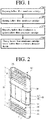
- FIG. 1 is a flowchart showing a method of manufacturing a hollow fiber membrane module according to an embodiment of the present disclosure
- FIG. 2 is a perspective view showing an example of an openable hollow fiber membrane cartridge used in the method of manufacturing the hollow fiber membrane module according to the embodiment of the present disclosure
- FIG. 3 is a plan view showing the state in which the openable hollow fiber membrane cartridge of FIG. 2 is open (unfolded).
- FIGS. 4 to 9 are perspective views showing various embodiments of the openable hollow fiber membrane cartridge.
- the method of manufacturing the hollow fiber membrane module includes a step of preparing a hollow fiber membrane cartridge (S100), a step of opening the hollow fiber membrane cartridge (S200), a step of disposing hollow fiber membranes in the opened hollow fiber membrane cartridge (S300), and a step of closing the hollow fiber membrane cartridge having the hollow fiber membranes disposed therein (S400).
- the hollow fiber membrane cartridge is prepared (S100).
- the hollow fiber membrane cartridge used in the present disclosure is an openable hollow fiber membrane cartridge 100 (hereinafter referred to as a "cartridge") shown in each of FIGS. 2 to 9 .
- the cartridge 100 includes a body unit 110 having a mesh unit 130 formed at each of the upper and lower parts thereof and a locking unit 120 configured to fasten the body unit 110.
- a hinge type locking unit 120 fastens the body unit 110.
- at least a portion of the body unit 110 is capable of being separated, and a sliding type locking unit 120 couples and fastens the body unit 110.
- the cartridge including the hinge type locking unit 120 will be described with reference to FIGS. 2 to 5 .
- the body unit 110 may be formed in a rectangular parallelepiped shape rounded at both side surfaces thereof, a cylindrical shape having a circular section, or an oval cylindrical shape having an oval section. This is only an illustration of the shape of the body unit 110, and the present disclosure is not limited thereto.
- the body unit 110 is preferably made of a material that has high dimensional stability, high resin flowability, and high resistance to thermal deformation. Examples of such a material include polycarbonate (PC), acrylonitrile butadiene styrene (ABS), and nylon.
- the body unit 110 includes a folding portion 111 configured to allow the cartridge 100 to be unfolded when the state in which the body unit 110 is locked by the locking unit 120 is released.
- the folding portion 111 is a groove formed inside the body unit 110.
- the folding portion 111 may be a V-shaped groove or a U-shaped groove.
- the body unit 110 includes a separation-preventing hook 112 configured to prevent the cartridge 100 from being separated from a housing unit 200 (see FIG. 12) when the cartridge 100 is inserted into the housing unit 200.
- the separation-preventing hook 112 may be formed in the shape of a protrusion formed on at least one of the upper surface or the lower surface of the body unit 110 so as to protrude a predetermined length therefrom.
- the locking unit 120 may be formed at one side surface of the body unit 110.
- the locking unit 120 includes a locking cover 121 connected to one side of the body unit 110 and a locking protrusion 122 formed at the other side of the body unit 110 so as to protrude therefrom.
- the locking unit 120 may include a locking protrusion (not shown) formed on the locking cover 121 and a locking recess (not shown) formed in the body unit such that the locking protrusion is inserted into the locking recess.
- the locking unit 120 may be configured to open the entire surface of one side of the body unit 110.
- the locking unit 120 includes a locking cover 121 configured to open or close the entire surface of one side of the body unit 110 and a locking protrusion 122 formed on the body unit 110 so as to protrude therefrom. In this case, it is not necessary to form the folding portion 111 at the body unit 110, whereby it is possible to improve durability of the cartridge 100.
- the locking unit 120 may be configured to open a portion of the upper surface of the body unit 110 in one direction.
- the lower surface and both side surfaces of the body unit 110 are integrally formed, the lower side 113 of the upper surface is formed integrally with the side surfaces of the body unit 110, and the upper side 114 of the upper surface of the body unit is capable of being separated from one of the side surfaces of the body unit 110 so as to open the body unit in one direction in a hinged fashion. That is, the upper side 114 of the upper surface of the body unit 110 is formed so as to be rotatable with a predetermined angle about the other side surface of the body unit 110 as an axis.
- the upper side 114 of the upper surface of the body unit 110 may perform the function of a locking cover, a locking protrusion (not shown) may be formed on the upper side 114 of the upper surface of the body unit 110, and a locking recess (not shown) may be formed in a portion corresponding thereto.
- a locking recess may be formed in the upper side 114 of the upper surface of the body unit 110, and a locking protrusion may be formed on a portion corresponding thereto.
- the cartridge including the sliding type locking unit 120 will be described with reference to FIGS. 6 to 9 .
- the locking unit 120 may be configured to slide along at least a portion of the body unit 110.
- the locking unit 120 slides along one side of the body unit 110 in order to open or close the body unit 110.
- One side surface of the body 110 may be capable of being separated in order to form the locking unit 120.
- the locking unit 120 may include a locking cover 121 configured to slide along one side of the body unit 110 in an upward-downward direction in order to open or close the body unit 110 and a sliding groove 123 formed at the one side of the body unit such that the locking cover can slide along the sliding groove.
- the locking cover 121 may be formed in a curved shape.
- the present disclosure is not limited thereto. In this case, it is not necessary to form the folding portion 111 at the body unit 110, whereby it is possible to improve durability of the cartridge 100.
- the body unit 110 is formed so as to be dividable into an upper surface 110a and a lower surface 110b. At least one of the upper surface 110a or the lower surface 110b performs the function of a locking cover.
- the upper surface 110a of the body unit 110 may be a locking cover.
- a sliding groove 123 may be formed in the lower surface 110b of the body unit 110 such that the upper surface 110a can slide along the sliding groove.
- the locking unit 120 may include the upper surface 110a of the body unit 110 and the sliding groove 123. Even in this case, it is not necessary to form the folding portion 111 at the body unit 110, whereby it is possible to improve durability of the cartridge 100.
- the cartridge 100 of FIG. 7 is useful when hollow fiber membranes in a wet state are inserted into the cartridge 100.
- the locking unit 120 is configured to open a portion of the upper surface of the body unit 110, in a similar manner to FIG. 5 .
- the lower surface and both side surfaces of the body unit 110 are integrally formed, the lower side 113 of the upper surface of the body unit is formed integrally with the side surfaces of the body unit 110, and the upper side 114 of the upper surface is capable of being separated from the side surfaces of the body unit 110 so as to open the body unit in a sliding fashion.
- the upper side 114 of the upper surface may perform the function of a locking cover.
- a sliding groove 123 may be formed in a portion of the lower surface 110b of the body unit 110 such that the upper side 114 of the upper surface can slide along the sliding groove.
- the locking unit 120 may include the upper side 114 of the upper surface of the body unit and the sliding groove 123. Even in this case, it is not necessary to form the folding portion 111 at the body unit 110, whereby it is possible to improve durability of the cartridge 100.
- the hollow fiber membranes in the dry state are inserted in an amount equivalent to only about half the capacity of the cartridge when the hollow fiber membranes are inserted higher than the height of the lower surface 110b, since there is no structure capable of supporting the hollow fiber membranes.
- the hollow fiber membranes in a dry state are inserted into the cartridge of FIG. 8 , on the other hand, it is possible to insert the hollow fiber membranes in the dry state in an amount equivalent to the capacity of the cartridge, since the lower side 113 of the upper surface integrally formed with the lower surface 110b serves as a structure capable of supporting the hollow fiber membranes in the dry state.
- hollow fiber membranes in a wet state may be inserted into the cartridge in an amount equivalent to the capacity of the cartridge since the hollow fiber membranes in the wet state are united with each other due to moisture.
- FIG. 9 exemplarily shows the case in which the body unit 110 of the cartridge 100 is generally formed in a cylindrical shape.
- a portion of the cylinder may be capable of being separated in order to form a locking cover, half of the cylinder may be capable of being separated in order to form a locking cover, or a portion of the cylinder may be integrally formed while the remaining portion of the cylinder may be capable of being separated in order to form a locking cover, and a sliding groove may be formed at a position corresponding to the locking cover.
- the locking cover and the sliding groove may constitute a locking unit.
- this is merely one illustration, and the shape of the body unit 110 of the cartridge 100 is not limited thereto.
- a mesh unit 130 is formed at each of the upper part and the lower part of the body unit 110.
- the mesh unit 130 allows a second fluid introduced through a second fluid inlet 231, a description of which will follow, to be introduced into the cartridge 100 through windows 132 such that moisture exchange is performed between the second fluid and a first fluid introduced through a first fluid inlet 221 in the cartridge 100.
- the mesh unit 130 may prevent a portion of the introduced second fluid from directly colliding with the hollow fiber membranes disposed in the cartridge 100, whereby it is possible to prevent damage to the hollow fiber membranes.
- each rib constituting the mesh unit 130 may guide the flow direction of the introduced second fluid, whereby it is possible to prevent damage to the hollow fiber membrane bundle located immediately below each rib 131. At this time, the extent to which the hollow fiber membrane bundle is damaged is changed depending on the corner curvature of each rib 131. Test results are shown in Table 1 below. [Table 1] R Number of cut fiber membranes 0.3 23 of 1800 fiber membranes 0.5 19 of 1800 fiber membranes 0.7 8 of 1800 fiber membranes 0.9 None of 1800 fiber membranes
- the corner curvature R of each rib 131 be 0.7 or more.
- the corner curvature R is equal to or less than 0.5, 1% or more of the total number of hollow fiber membranes is cut, which may adversely affect overall humidification efficiency.
- the corner curvature R is equal to or greater than 0.7, on the other hand, only a few of the hollow fiber membranes are cut, and therefore the effect thereof on overall humidification efficiency is insignificant.
- the length L2+L3 of the mesh unit 130 is set so as to be equivalent to 10 to 70% of the overall length L1 of the cartridge, and the total area of the windows 132 formed so as to be surrounded by the ribs 131 is set so as to be equivalent to 30 to 70% of the overall area of the cartridge.
- the total area of the windows 132 exceeds 70% of the overall area of the cartridge, the size of the space in which the second fluid introduced through the second fluid inlet 231 is capable of transferring moisture through the hollow fiber membranes is reduced, which adversely affects overall humidification efficiency.
- the mesh unit 130 is included, whereby it is possible to prevent the hollow fiber membranes from being cut, and therefore no separate mesh net is necessary.
- the locking unit 120 formed at the side surface of the body unit 110 is pulled to release the coupled state between the locking cover 121 and the locking protrusion 122 and thus to open the body unit 110.
- the locking cover is slid in one direction to open the side surface of the body unit 110.
- hollow fiber membranes are disposed in the cartridge 100 in the state in which the hollow fiber membrane cartridge 100 is open (S300). At this time, hollow fiber membranes in a dry state may be disposed. Alternatively, hollow fiber membranes in a wet state may be disposed.
- Hollow fiber membranes are washed and are then sufficiently dried.
- the hollow fiber membranes in a dry state are disposed in the cartridge 100.
- the hollow fiber membranes are disposed in the right part of the body unit 110 (the part of the body unit at which the locking cover is formed) in an open state, shown in FIG. 3 .
- the locking unit 120 is configured to open the entire surface of one side of the body unit 110, as shown in FIG. 4 , or in the case in which the locking unit 120 is configured to slide along one side of the body unit 110, as shown in FIG. 6 , the entire surface of one side of the body unit 110 may be opened, the cartridge 100 may be positioned such that the opened entire surface of one side of the body unit 110 faces upwards, and hollow fiber membranes H may be inserted into the cartridge 100 such that the longitudinal direction of each of the hollow fiber membranes is parallel to the opened side of the body unit 110, whereby the hollow fiber membranes may be easily disposed in the cartridge 100.
- the locking unit 120 is configured to open a portion of the upper surface of the body unit 110 in one direction, as shown in FIG. 5 or 8 , the upper side 114 of the upper surface of the body unit 110 is opened, and hollow fiber membranes in a dry state or a wet state are disposed in the opened portion of the body unit.
- the upper surface 110a of the body unit is slid so as open the body unit, as shown in FIG. 7 , the upper surface 110a of the body unit is opened, and hollow fiber membranes in a wet state are disposed in the opened portion of the body unit.
- the hollow fiber membranes are disposed in the cartridge in the state in which the cartridge is open, and therefore damage to the hollow fiber membranes, which occurs when the hollow fiber membranes are inserted into a closed type cartridge, as in the conventional art, does not occur.
- hollow fiber membranes may be washed, and then the hollow fiber membranes in a wet state may be disposed in the cartridge 100 without being dried. That is, in a conventional hollow fiber membrane insertion process, dried hollow fiber membranes must be used in order to insert hollow fiber membranes into a closed type cartridge. In the present disclosure, however, hollow fiber membranes are not inserted into a cartridge but are disposed in the cartridge in an open state. Consequently, it is possible to dispose not only hollow fiber membranes in a wet state but also hollow fiber membranes in a dry state in the cartridge.
- the hollow fiber membrane cartridge in which the hollow fiber membranes are disposed, is closed (S400).
- the locking cover 121 and the locking protrusion 122 are fastened to each other to close the cartridge.
- the locking cover 121 is slid in the other direction to close the body unit 110.
- the ends of the hollow fiber membranes are bound and potted. Gaps between the hollow fiber membranes are filled through a potting process.
- the potting process may be performed in the step of disposing the hollow fiber membranes in the cartridge (S300), although the potting process may be performed after the cartridge is closed. That is, a hollow fiber membrane bundle may be formed using a plurality of hollow fiber membranes, the ends of hollow fiber membrane bundles may be bound and potted, and the potted hollow fiber membrane bundles may be disposed in the cartridge.
- the hollow fiber membranes are disposed in the openable hollow fiber membrane cartridge and then the cartridge is closed through the above processes, whereby the cartridge 100 is manufactured.
- One or more cartridges 100 are manufactured and disposed in a housing unit 200, as shown in FIG. 11 .
- the hollow fiber membrane module according to the embodiment of the present disclosure at least one cartridge 100 is disposed in a housing unit 200, and hollow fiber membranes are housed in the cartridge.
- the cartridge is manufactured using the above method, and includes a body unit 110 having a mesh unit 130 formed at each of the upper part and the lower part thereof and a locking unit 120 configured to lock the body unit 110.
- the hollow fiber membrane module includes a housing unit 200 and at least one cartridge 100 installed in the housing unit 200, the housing unit having a plurality of hollow fiber membranes housed therein.
- the housing unit 200 defines the external appearance of the hollow fiber membrane module.
- the housing unit 200 may include a housing body 210 and housing caps 220, which may be integrally coupled to each other.
- Each of the housing body 210 and the housing caps 220 may be made of hard plastic, such as polypropylene 5 (PP5), polyphenylene sulfide (PPS), polyamide 6 (PA6), polyamide 66 (PA66), polyphthalamide (PPA), or polycarbonate, or metal.
- each of the housing body 210 and the housing caps 220 may be a polygon or a circle.
- the polygon may be a rectangle, a square, a trapezoid, a parallelogram, a pentagon, or a hexagon, and corners of the polygon may be round.
- the circle may be an oval.
- the housing body 210 is provided in both ends thereof with a second fluid inlet 231, through which a second fluid is introduced, and a second fluid outlet 232, through which the second fluid is discharged.
- At least one cartridge 100 in which a plurality of hollow fiber membranes configured to allow moisture to selectively pass therethrough are housed, is disposed in the housing unit 200.
- each of the hollow fiber membranes is made of a known material, and therefore a detailed description thereof will be omitted from this specification.
- the cartridge 100 is provided at both ends thereof with potting units (not shown) configured to bind the hollow fiber membranes and to fill gaps between the hollow fiber membranes. As a result, the both ends of the cartridge 100 are blocked by the potting units, whereby a flow channel configured to allow the second fluid to pass therethrough is defined in the cartridge.
- potting units are made of a known material, and therefore a detailed description thereof will be omitted from this specification.
- the housing caps 220 are coupled to both ends of the housing body 210.
- a first fluid inlet 221 and a first fluid outlet 222 are formed in the housing caps 220.
- a first fluid introduced through the first fluid inlet 221 formed in one of the housing caps 220 is introduced into the cartridge, flows through an inner pipeline of each of the hollow fiber membranes, flows out of the cartridge, and is discharged outside through the first fluid outlet 222 formed in the other housing cap 220.
- At least one insertion hole 240 in which the cartridge 100 can be mounted, is formed in the housing unit 200, and the cartridge 100 is inserted into the insertion hole 240.
- a protrusion of a separation-preventing hook 112 formed on the cartridge protrudes from the end of the insertion hole 240, whereby the mounting of the cartridge 100 is completed.
- the withdrawal of the cartridge from the insertion hole in the reverse direction is prevented by the protrusion of a separation-preventing hook 112, whereby it is possible to prevent the cartridge 100 mounted in the insertion hole 240 from being separated from the insertion hole in the reverse direction.
- the cartridge 100 may be pushed in the direction opposite the insertion direction thereof in the state in which the protrusion is pushed with strong force, whereby the cartridge 100 may be withdrawn from the insertion hole.
- the first fluid may be a low-humidity fluid
- the second fluid may be a high-humidity fluid
- the first fluid may be a high-humidity fluid
- the first fluid is introduced into the housing unit 200 and the cartridge 100 through the first fluid inlet 221 formed in one of the housing caps 220, flows in the hollow fiber membranes, and is discharged out of the hollow fiber membrane module through the first fluid outlet 222 formed in the other housing cap 220. Meanwhile, the first fluid may be introduced through the first fluid outlet 222 and may then flow in the direction in which the first fluid is discharged through the first fluid inlet 221.
- the second fluid is introduced into the housing body 210 through the second fluid inlet 231 of the housing body 210, flows outside the hollow fiber membranes through a mesh unit 130a of the cartridge 100, flows into the housing body 210 through a mesh unit 130b of the cartridge 100, and is discharged outside through the second fluid outlet 232 of the housing body 210.
- the second fluid may be introduced through the second fluid outlet 232 and may then flow in the direction in which the second fluid is discharged through the second fluid inlet 231. That is, the first fluid and the second fluid may flow in opposite directions, or may flow in the same direction.
- the first fluid and the second fluid flow inside and outside the hollow fiber membranes, and exchange a substance, such as moisture, or heat with each other through the hollow fiber membranes.
- Hollow fiber membrane cartridge 110 Body unit 120: Locking unit 130: Mesh unit 200: Housing unit 210: Housing body 220: Housing cap 240: Insertion hole
Landscapes
- Chemical & Material Sciences (AREA)
- Chemical Kinetics & Catalysis (AREA)
- Engineering & Computer Science (AREA)
- Manufacturing & Machinery (AREA)
- Life Sciences & Earth Sciences (AREA)
- Sustainable Development (AREA)
- Sustainable Energy (AREA)
- Electrochemistry (AREA)
- General Chemical & Material Sciences (AREA)
- Separation Using Semi-Permeable Membranes (AREA)
- Fuel Cell (AREA)
Abstract
Description
- The present disclosure relates to a method of manufacturing a hollow fiber membrane module using an openable hollow fiber membrane cartridge and a hollow fiber membrane module manufactured by the same.
- A fuel cell is a power generation cell that combines hydrogen and oxygen to generate electricity. Such a fuel cell has advantages in that it is possible to continuously generate electricity as long as hydrogen and oxygen are supplied, unlike a general chemical cell, such as a dry cell or a storage cell, and in that there is no heat loss, whereby efficiency of the fuel cell is about twice as high as efficiency of an internal combustion engine.
- In addition, the fuel cell directly converts chemical energy generated by combination of hydrogen and oxygen into electrical energy, whereby the volume of contaminants that are discharged is small. Consequently, the fuel cell has advantages in that the fuel cell is environmentally friendly and in that a concern about depletion of resources due to an increase in energy consumption can be reduced.
- Based on the kind of an electrolyte that is used, such a fuel cell may be generally classified as a polymer electrolyte membrane fuel cell (PEMFC), a phosphoric acid fuel cell (PAFC), a molten carbonate fuel cell (MCFC), a solid oxide fuel cell (SOFC), or an alkaline fuel cell (AFC) .
- These fuel cells are operated fundamentally by the same principle, but are different from each other in terms of the kind of fuel that is used, operating temperature, catalyst, and electrolyte. Among these fuel cells, the polymer electrolyte membrane fuel cell is known as being the most favorable to a transportation system as well as small-scale stationary power generation equipment, since the polymer electrolyte membrane fuel cell is operated at a lower temperature than the other fuel cells and the output density of the polymer electrolyte membrane fuel cell is high, whereby it is possible to miniaturize the polymer electrolyte membrane fuel cell.
- One of the most important factors to improve the performance of the polymer electrolyte membrane fuel cell is to supply a predetermined amount or more of moisture to a polymer electrolyte membrane (PEM) (also referred to as a proton exchange membrane) of a membrane electrode assembly (MEA) in order to retain water content. The reason for this is that, in the case in which the polymer electrolyte membrane becomes dry, power generation efficiency is abruptly reduced.
- 1) A bubbler humidification method of filling a pressure-resistant container with water and allowing a target gas to pass through a diffuser in order to supply moisture, 2) a direct injection method of calculating the amount of moisture to be supplied that is necessary for fuel cell reaction and directly supplying moisture to a gas stream pipe through a solenoid valve, and 3) a humidification membrane method of supplying moisture to a gas fluid bed using a polymer separation membrane are used as methods of humidifying the polymer electrolyte membrane.
- Among these methods, the humidification membrane method, which provides water vapor to a gas that is supplied to the polymer electrolyte membrane using a membrane configured to selectively transmit only water vapor included in an exhaust gas in order to humidify the polymer electrolyte membrane, is advantageous in that it is possible to reduce the weight and size of a humidifier.
- In the case in which a module is formed, a hollow fiber membrane having large transmission area per unit volume is preferably used as the selective transmission membrane used in the humidification membrane method. That is, in the case in which a membrane humidifier is manufactured using a hollow fiber membrane, high integration of the hollow fiber membranes having large contact surface area is possible, whereby it is possible to sufficiently humidify a fuel cell even in the case of a small capacity, it is possible to use a low-priced material, and it is possible to collect moisture and heat included in a non-reaction gas discharged from the fuel cell at a high temperature and to reuse the collected moisture and heat through the humidifier.
- In the case of the humidifier using the hollow fiber membrane, however, a plurality of hollow fiber membranes is integrated in order to increase the capacity of the humidifier. In this case, the flow of a gas that flows outside the hollow fiber membranes is not uniform in the entirety of the humidifier due to resistance caused by the highly integrated hollow fiber membranes.
- In order to solve this, a hollow fiber membrane module is configured to have a plurality of cartridges, which is mounted in a membrane humidifier housing in order to achieve uniform flow of a gas. That is, a hollow fiber membrane bundle is housed in each cartridge, and a plurality of cartridges is mounted in the membrane humidifier housing such that a gas introduced into the membrane humidifier housing flows in the cartridges, whereby the flow of the gas is uniform.
- However, a conventional cartridge system has the following problems in manufacture.
- The conventional cartridge system uses a closed type cartridge that is open at the upper and lower surfaces thereof and is closed at the side surface thereof. Consequently, hollow fiber membranes in a dry state must be inserted into the cartridge in a longitudinal direction of the cartridge in the state in which the cartridge is stood on end. In the case in which hollow fiber membranes in a dry state are inserted into the cartridge, the hollow fiber membranes are bent during insertion thereof.
- In a process of inserting a plurality of hollow fiber membranes in a dry state into the cartridge, hollow fiber membranes are damaged due to various causes, such as friction between hollow fiber membranes that have already been inserted and hollow fiber membranes that are being inserted or disturbance occurring during insertion of hollow fiber membranes.
- Also, in order to insert hollow fiber membranes in a dry state into the cartridge without damage thereto, the hollow fiber membranes must be inserted somewhat sparsely, whereby the packing density (PD) of the hollow fiber membranes is reduced.
- Also, in order to insert hollow fiber membranes into the cartridge without damage thereto, it is necessary for a worker to carefully insert the hollow fiber membranes into the cartridge, which leads to an increase in process time and manpower requirement.
- The present disclosure has been made in view of the above problems, and it is an object of the present disclosure to provide a method of manufacturing a hollow fiber membrane module capable of preventing damage to a hollow fiber membrane bundle and a decrease in packing density of the hollow fiber membrane bundle caused in a process of inserting the hollow fiber membrane bundle into a cartridge and capable of reducing process time and manpower requirement and a hollow fiber membrane module manufactured by the same.
- A method of manufacturing a hollow fiber membrane module according to an embodiment of the present disclosure includes:
- preparing a hollow fiber membrane cartridge; opening the hollow fiber membrane cartridge; disposing hollow fiber membranes in the opened hollow fiber membrane cartridge; and closing the hollow fiber membrane cartridge having the hollow fiber membranes disposed therein.
- In the method of manufacturing the hollow fiber membrane module according to the embodiment of the present disclosure, the hollow fiber membrane cartridge may include a body unit having a mesh unit formed at each of the upper part and the lower part thereof and a locking unit configured to fasten the body unit in a hinged fashion.
- In the method of manufacturing the hollow fiber membrane module according to the embodiment of the present disclosure, the locking unit may include a locking cover formed at one side of the body unit and a locking protrusion formed at the other side of the body unit so as to protrude therefrom.
- In the method of manufacturing the hollow fiber membrane module according to the embodiment of the present disclosure, the locking unit may include a locking cover configured to open the entire surface of one side of the body unit and a locking protrusion formed on the body unit so as to protrude therefrom.
- In the method of manufacturing the hollow fiber membrane module according to the embodiment of the present disclosure, the lower surface of the body unit, both side surfaces of the body unit, and the lower side of the upper surface of the body unit may be integrally formed, and
the upper side of the upper surface of the body unit may be capable of being separated from one of the side surfaces of the body unit so as open the body unit in one direction. - In the method of manufacturing the hollow fiber membrane module according to the embodiment of the present disclosure, the hollow fiber membrane cartridge may include a body unit having a mesh unit formed at each of the upper part and the lower part thereof and a locking unit configured to fasten the body unit in a sliding fashion.
- In the method of manufacturing the hollow fiber membrane module according to the embodiment of the present disclosure, the locking unit may include a locking cover configured to slide along one side of the body unit in order to open or close the body unit and a sliding groove formed at the one side of the body unit such that the locking cover can slide along the sliding groove.
- In the method of manufacturing the hollow fiber membrane module according to the embodiment of the present disclosure, the body unit may be formed so as to be dividable into an upper surface and a lower surface, one of the upper surface and the lower surface of the body unit may be a locking cover configured to slide along the other surface in order to open or close the body unit, and
- the other surface may be provided with a sliding groove configured to allow the locking cover to slide therealong.
- In the method of manufacturing the hollow fiber membrane module according to the embodiment of the present disclosure, the lower surface of the body unit, both side surfaces of the body unit, and the lower side of the upper surface of the body unit may be integrally formed, the upper side of the upper surface of the body unit may be formed so as to be capable of being separated from the side surfaces of the body unit, the upper side of the upper surface of the body unit may be a locking cover configured to slide in order to open or close the body unit, and the lower surface of the body unit may be provided with a sliding groove configured to allow the upper side of the upper surface to slide therealong.
- In the method of manufacturing the hollow fiber membrane module according to the embodiment of the present disclosure, the mesh unit may include a plurality of ribs configured to guide the flow direction of a fluid and a window formed so as to be surrounded by the plurality of ribs, wherein the corner curvature of each of the ribs may be 0.7 or more.
- A hollow fiber membrane module according to an embodiment of the present disclosure includes:
a housing unit including a first fluid inlet, a first fluid outlet, a second fluid inlet, and a second fluid outlet; and at least one openable cartridge installed in the housing unit, the openable cartridge having a plurality of hollow fiber membranes housed therein. - In the hollow fiber membrane module according to the embodiment of the present disclosure, the hollow fiber membrane cartridge may include a body unit having a mesh unit formed at each of the upper part and the lower part thereof and a locking unit configured to fasten the body unit in a hinged fashion.
- In the hollow fiber membrane module according to the embodiment of the present disclosure, the locking unit may include a locking cover formed at one side of the body unit and a locking protrusion formed at the other side of the body unit so as to protrude therefrom.
- In the hollow fiber membrane module according to the embodiment of the present disclosure, the locking unit may include a locking cover configured to open the entire surface of one side of the body unit and a locking protrusion formed on the body unit so as to protrude therefrom.
- In the hollow fiber membrane module according to the embodiment of the present disclosure, the lower surface of the body unit, both side surfaces of the body unit, and the lower side of the upper surface of the body unit may be integrally formed, and the upper side of the upper surface of the body unit may be capable of being separated from one of the side surfaces of the body unit so as to open the body unit in one direction.
- In the hollow fiber membrane module according to the embodiment of the present disclosure, the hollow fiber membrane cartridge may include a body unit having a mesh unit formed at each of the upper part and the lower part thereof and a locking unit configured to fasten the body unit in a sliding fashion.
- In the hollow fiber membrane module according to the embodiment of the present disclosure, the locking unit may include a locking cover configured to slide along one side of the body unit in order to open or close the body unit and a sliding groove formed at the one side of the body unit such that the locking cover can slide along the sliding groove.
- In the hollow fiber membrane module according to the embodiment of the present disclosure, the body unit may be formed so as to be dividable into an upper surface and a lower surface, one of the upper surface and the lower surface of the body unit may be a locking cover configured to slide along the other surface in order to open or close the body unit, and the other surface may be provided with a sliding groove configured to allow the locking cover to slide therealong.
- In the hollow fiber membrane module according to the embodiment of the present disclosure, the lower surface of the body unit, both side surfaces of the body unit, and the lower side of the upper surface of the body unit may be integrally formed, the upper side of the upper surface of the body unit may be formed so as to be capable of being separated from the side surfaces of the body unit, the upper side of the upper surface of the body unit may be a locking cover configured to slide in order to open or close the body unit, and the lower surface of the body unit may be provided with a sliding groove configured to allow the upper side of the upper surface to slide therealong.
- In the hollow fiber membrane module according to the embodiment of the present disclosure, the mesh unit may include a plurality of ribs configured to guide the flow direction of a fluid and a window formed so as to be surrounded by the plurality of ribs, wherein the corner curvature of each of the ribs may be 0.7 or more.
- The details of other embodiments according to various aspects of the present disclosure are included in the following detailed description of the present disclosure.
- According to embodiments of the present disclosure, hollow fiber membranes are disposed in the state in which a cartridge is open, whereby it is possible to prevent damage to hollow fiber membranes caused when the hollow fiber membranes are inserted into the cartridge as in the conventional art.
- In addition, since there is no concern of hollow fiber membranes being damaged during disposition thereof, it is possible to dispose hollow fiber membranes in the cartridge at higher density than in the conventional art, whereby it is possible to increase packing density (PD) of a hollow fiber membrane bundle.
- In addition, it is sufficient to appropriately dispose the hollow fiber membranes in the opened cartridge, whereby it is possible to reduce worker labor more than in the case in which the hollow fiber membranes are inserted into a closed type cartridge, and therefore it is possible to reduce process time and manpower requirement.
- Also, in a conventional hollow fiber membrane insertion process, dried hollow fiber membranes must be used in order to insert hollow fiber membranes into a closed type cartridge. In the present disclosure, however, hollow fiber membranes are not inserted into the cartridge but are disposed in the cartridge in an open state. Consequently, it is possible to dispose not only hollow fiber membranes in a wet state but also hollow fiber membranes in a dry state in the cartridge.
- In addition, conventionally, a separate mesh net is necessary to prevent the hollow fiber membranes from being cut. In the cartridge according to the present disclosure, however, a mesh unit is included, whereby it is possible to prevent the hollow fiber membranes from being cut, and therefore no separate mesh net is necessary.
-
-
FIG. 1 is a flowchart showing a method of manufacturing a hollow fiber membrane module according to an embodiment of the present disclosure. -
FIG. 2 is a perspective view showing an example of an openable hollow fiber membrane cartridge used in the method of manufacturing the hollow fiber membrane module according to the embodiment of the present disclosure. -
FIG. 3 is a plan view showing the state in which the openable hollow fiber membrane cartridge ofFIG. 2 is open (unfolded). -
FIGS. 4 to 9 are perspective views showing various embodiments of the openable hollow fiber membrane cartridge. -
FIG. 10 is a sectional view taken along line A-A' ofFIG. 2 , showing the flow direction of a fluid that is introduced through a mesh unit. -
FIG. 11 is an exploded perspective view showing a hollow fiber membrane module according to an embodiment of the present disclosure. - The present disclosure may be changed in various manners and may have various embodiments, wherein specific embodiments will be illustrated and described in detail in the following detailed description. However, the present disclosure is not limited to the specific embodiments, and it should be understood that the present disclosure includes all modifications, equivalents, or substitutions included in the idea and technical scope of the present disclosure.
- The terms used in the present disclosure are provided only to describe the specific embodiments, and do not limit the present disclosure. Singular forms are intended to include plural forms as well, unless the context clearly indicates otherwise. In the present disclosure, it should be understood that the terms "includes," "has," etc. specify the presence of features, numbers, steps, operations, elements, components, or combinations thereof described in the specification, but do not preclude the presence or addition of one or more other features, numbers, steps, operations, elements, components, or combinations thereof. Hereinafter, fuel cell membrane humidifiers according to embodiments of the present disclosure will be described with reference to the accompanying drawings.
-
FIG. 1 is a flowchart showing a method of manufacturing a hollow fiber membrane module according to an embodiment of the present disclosure,FIG. 2 is a perspective view showing an example of an openable hollow fiber membrane cartridge used in the method of manufacturing the hollow fiber membrane module according to the embodiment of the present disclosure,FIG. 3 is a plan view showing the state in which the openable hollow fiber membrane cartridge ofFIG. 2 is open (unfolded).FIGS. 4 to 9 are perspective views showing various embodiments of the openable hollow fiber membrane cartridge. - As shown in
FIG. 1 , the method of manufacturing the hollow fiber membrane module according to the embodiment of the present disclosure includes a step of preparing a hollow fiber membrane cartridge (S100), a step of opening the hollow fiber membrane cartridge (S200), a step of disposing hollow fiber membranes in the opened hollow fiber membrane cartridge (S300), and a step of closing the hollow fiber membrane cartridge having the hollow fiber membranes disposed therein (S400). - First, the hollow fiber membrane cartridge is prepared (S100).
- The hollow fiber membrane cartridge used in the present disclosure is an openable hollow fiber membrane cartridge 100 (hereinafter referred to as a "cartridge") shown in each of
FIGS. 2 to 9 . Thecartridge 100 includes abody unit 110 having amesh unit 130 formed at each of the upper and lower parts thereof and alocking unit 120 configured to fasten thebody unit 110. - In the
cartridge 100 shown in each ofFIGS. 2 to 5 , a hingetype locking unit 120 fastens thebody unit 110. In thecartridge 100 shown in each ofFIGS. 6 to 9 , at least a portion of thebody unit 110 is capable of being separated, and a slidingtype locking unit 120 couples and fastens thebody unit 110. - First, the cartridge including the hinge
type locking unit 120 will be described with reference toFIGS. 2 to 5 . - Referring to
FIGS. 2 and3 , thebody unit 110 may be formed in a rectangular parallelepiped shape rounded at both side surfaces thereof, a cylindrical shape having a circular section, or an oval cylindrical shape having an oval section. This is only an illustration of the shape of thebody unit 110, and the present disclosure is not limited thereto. - The
body unit 110 is preferably made of a material that has high dimensional stability, high resin flowability, and high resistance to thermal deformation. Examples of such a material include polycarbonate (PC), acrylonitrile butadiene styrene (ABS), and nylon. Thebody unit 110 includes afolding portion 111 configured to allow thecartridge 100 to be unfolded when the state in which thebody unit 110 is locked by thelocking unit 120 is released. Thefolding portion 111 is a groove formed inside thebody unit 110. For example, thefolding portion 111 may be a V-shaped groove or a U-shaped groove. - The
body unit 110 includes a separation-preventinghook 112 configured to prevent thecartridge 100 from being separated from a housing unit 200 (see FIG. 12) when thecartridge 100 is inserted into thehousing unit 200. The separation-preventinghook 112 may be formed in the shape of a protrusion formed on at least one of the upper surface or the lower surface of thebody unit 110 so as to protrude a predetermined length therefrom. - The
locking unit 120 may be formed at one side surface of thebody unit 110. Thelocking unit 120 includes a lockingcover 121 connected to one side of thebody unit 110 and a lockingprotrusion 122 formed at the other side of thebody unit 110 so as to protrude therefrom. However, the present disclosure is not limited thereto. Thelocking unit 120 may include a locking protrusion (not shown) formed on the lockingcover 121 and a locking recess (not shown) formed in the body unit such that the locking protrusion is inserted into the locking recess. - As shown in
FIG. 4 , thelocking unit 120 may be configured to open the entire surface of one side of thebody unit 110. In this case, thelocking unit 120 includes a lockingcover 121 configured to open or close the entire surface of one side of thebody unit 110 and a lockingprotrusion 122 formed on thebody unit 110 so as to protrude therefrom. In this case, it is not necessary to form thefolding portion 111 at thebody unit 110, whereby it is possible to improve durability of thecartridge 100. - As shown in
FIG. 5 , thelocking unit 120 may be configured to open a portion of the upper surface of thebody unit 110 in one direction. In this case, the lower surface and both side surfaces of thebody unit 110 are integrally formed, thelower side 113 of the upper surface is formed integrally with the side surfaces of thebody unit 110, and theupper side 114 of the upper surface of the body unit is capable of being separated from one of the side surfaces of thebody unit 110 so as to open the body unit in one direction in a hinged fashion. That is, theupper side 114 of the upper surface of thebody unit 110 is formed so as to be rotatable with a predetermined angle about the other side surface of thebody unit 110 as an axis. In this case, theupper side 114 of the upper surface of thebody unit 110 may perform the function of a locking cover, a locking protrusion (not shown) may be formed on theupper side 114 of the upper surface of thebody unit 110, and a locking recess (not shown) may be formed in a portion corresponding thereto. Of course, a locking recess may be formed in theupper side 114 of the upper surface of thebody unit 110, and a locking protrusion may be formed on a portion corresponding thereto. - Next, the cartridge including the sliding
type locking unit 120 will be described with reference toFIGS. 6 to 9 . As shown inFIGS. 6 to 9 , thelocking unit 120 may be configured to slide along at least a portion of thebody unit 110. - In the
cartridge 100 shown inFIG. 6 , thelocking unit 120 slides along one side of thebody unit 110 in order to open or close thebody unit 110. One side surface of thebody 110 may be capable of being separated in order to form thelocking unit 120. Thelocking unit 120 may include a lockingcover 121 configured to slide along one side of thebody unit 110 in an upward-downward direction in order to open or close thebody unit 110 and a slidinggroove 123 formed at the one side of the body unit such that the locking cover can slide along the sliding groove. As shown, the lockingcover 121 may be formed in a curved shape. However, the present disclosure is not limited thereto. In this case, it is not necessary to form thefolding portion 111 at thebody unit 110, whereby it is possible to improve durability of thecartridge 100. - In the
cartridge 100 shown inFIG. 7 , thebody unit 110 is formed so as to be dividable into anupper surface 110a and alower surface 110b. At least one of theupper surface 110a or thelower surface 110b performs the function of a locking cover. For example, theupper surface 110a of thebody unit 110 may be a locking cover. In this case, a slidinggroove 123 may be formed in thelower surface 110b of thebody unit 110 such that theupper surface 110a can slide along the sliding groove. At this time, thelocking unit 120 may include theupper surface 110a of thebody unit 110 and the slidinggroove 123. Even in this case, it is not necessary to form thefolding portion 111 at thebody unit 110, whereby it is possible to improve durability of thecartridge 100. In particular, thecartridge 100 ofFIG. 7 is useful when hollow fiber membranes in a wet state are inserted into thecartridge 100. - In the
cartridge 100 shown inFIG. 8 , thelocking unit 120 is configured to open a portion of the upper surface of thebody unit 110, in a similar manner toFIG. 5 . The lower surface and both side surfaces of thebody unit 110 are integrally formed, thelower side 113 of the upper surface of the body unit is formed integrally with the side surfaces of thebody unit 110, and theupper side 114 of the upper surface is capable of being separated from the side surfaces of thebody unit 110 so as to open the body unit in a sliding fashion. Theupper side 114 of the upper surface may perform the function of a locking cover. A slidinggroove 123 may be formed in a portion of thelower surface 110b of thebody unit 110 such that theupper side 114 of the upper surface can slide along the sliding groove. At this time, thelocking unit 120 may include theupper side 114 of the upper surface of the body unit and the slidinggroove 123. Even in this case, it is not necessary to form thefolding portion 111 at thebody unit 110, whereby it is possible to improve durability of thecartridge 100. - In the case in which hollow fiber membranes in a dry state are inserted into the cartridge of
FIG. 7 , the hollow fiber membranes in the dry state are inserted in an amount equivalent to only about half the capacity of the cartridge when the hollow fiber membranes are inserted higher than the height of thelower surface 110b, since there is no structure capable of supporting the hollow fiber membranes. In the case in which hollow fiber membranes in a dry state are inserted into the cartridge ofFIG. 8 , on the other hand, it is possible to insert the hollow fiber membranes in the dry state in an amount equivalent to the capacity of the cartridge, since thelower side 113 of the upper surface integrally formed with thelower surface 110b serves as a structure capable of supporting the hollow fiber membranes in the dry state. Even in the case in which the cartridge ofFIG. 7 is used, hollow fiber membranes in a wet state may be inserted into the cartridge in an amount equivalent to the capacity of the cartridge since the hollow fiber membranes in the wet state are united with each other due to moisture. -
FIG. 9 exemplarily shows the case in which thebody unit 110 of thecartridge 100 is generally formed in a cylindrical shape. Similarly toFIGS. 6 to 8 , a portion of the cylinder may be capable of being separated in order to form a locking cover, half of the cylinder may be capable of being separated in order to form a locking cover, or a portion of the cylinder may be integrally formed while the remaining portion of the cylinder may be capable of being separated in order to form a locking cover, and a sliding groove may be formed at a position corresponding to the locking cover. The locking cover and the sliding groove may constitute a locking unit. However, this is merely one illustration, and the shape of thebody unit 110 of thecartridge 100 is not limited thereto. - A
mesh unit 130 is formed at each of the upper part and the lower part of thebody unit 110. Themesh unit 130 allows a second fluid introduced through a secondfluid inlet 231, a description of which will follow, to be introduced into thecartridge 100 throughwindows 132 such that moisture exchange is performed between the second fluid and a first fluid introduced through a firstfluid inlet 221 in thecartridge 100. Themesh unit 130 may prevent a portion of the introduced second fluid from directly colliding with the hollow fiber membranes disposed in thecartridge 100, whereby it is possible to prevent damage to the hollow fiber membranes. - As shown in
FIG. 10 , each rib constituting themesh unit 130 may guide the flow direction of the introduced second fluid, whereby it is possible to prevent damage to the hollow fiber membrane bundle located immediately below eachrib 131. At this time, the extent to which the hollow fiber membrane bundle is damaged is changed depending on the corner curvature of eachrib 131. Test results are shown in Table 1 below.[Table 1] R Number of cut fiber membranes 0.3 23 of 1800 fiber membranes 0.5 19 of 1800 fiber membranes 0.7 8 of 1800 fiber membranes 0.9 None of 1800 fiber membranes - Referring to Table 1 above, it is preferable that the corner curvature R of each
rib 131 be 0.7 or more. In the case in which the corner curvature R is equal to or less than 0.5, 1% or more of the total number of hollow fiber membranes is cut, which may adversely affect overall humidification efficiency. In the case in which the corner curvature R is equal to or greater than 0.7, on the other hand, only a few of the hollow fiber membranes are cut, and therefore the effect thereof on overall humidification efficiency is insignificant. - The length L2+L3 of the
mesh unit 130 is set so as to be equivalent to 10 to 70% of the overall length L1 of the cartridge, and the total area of thewindows 132 formed so as to be surrounded by theribs 131 is set so as to be equivalent to 30 to 70% of the overall area of the cartridge. In the case in which the total area of thewindows 132 exceeds 70% of the overall area of the cartridge, the size of the space in which the second fluid introduced through the secondfluid inlet 231 is capable of transferring moisture through the hollow fiber membranes is reduced, which adversely affects overall humidification efficiency. - Meanwhile, conventionally, a separate mesh net is necessary to prevent the hollow fiber membranes from being cut. In the
cartridge 100 according to the present disclosure, however, themesh unit 130 is included, whereby it is possible to prevent the hollow fiber membranes from being cut, and therefore no separate mesh net is necessary. - Subsequently, the
cartridge 100 prepared as described above is opened (S200). - In the case of the cartridge including the hinge type locking unit, as shown in
FIGS. 2 to 5 , thelocking unit 120 formed at the side surface of thebody unit 110 is pulled to release the coupled state between the lockingcover 121 and the lockingprotrusion 122 and thus to open thebody unit 110. - In the case of the cartridge including the sliding type locking unit, as shown in
FIGS. 6 to 9 , the locking cover is slid in one direction to open the side surface of thebody unit 110. - Subsequently, hollow fiber membranes are disposed in the
cartridge 100 in the state in which the hollowfiber membrane cartridge 100 is open (S300). At this time, hollow fiber membranes in a dry state may be disposed. Alternatively, hollow fiber membranes in a wet state may be disposed. - Hollow fiber membranes are washed and are then sufficiently dried. The hollow fiber membranes in a dry state are disposed in the
cartridge 100. The hollow fiber membranes are disposed in the right part of the body unit 110 (the part of the body unit at which the locking cover is formed) in an open state, shown inFIG. 3 . - Meanwhile, in the case in which the
locking unit 120 is configured to open the entire surface of one side of thebody unit 110, as shown inFIG. 4 , or in the case in which thelocking unit 120 is configured to slide along one side of thebody unit 110, as shown inFIG. 6 , the entire surface of one side of thebody unit 110 may be opened, thecartridge 100 may be positioned such that the opened entire surface of one side of thebody unit 110 faces upwards, and hollow fiber membranes H may be inserted into thecartridge 100 such that the longitudinal direction of each of the hollow fiber membranes is parallel to the opened side of thebody unit 110, whereby the hollow fiber membranes may be easily disposed in thecartridge 100. - Meanwhile, in the case in which the
locking unit 120 is configured to open a portion of the upper surface of thebody unit 110 in one direction, as shown inFIG. 5 or8 , theupper side 114 of the upper surface of thebody unit 110 is opened, and hollow fiber membranes in a dry state or a wet state are disposed in the opened portion of the body unit. - Meanwhile, in the case in which the
upper surface 110a of the body unit is slid so as open the body unit, as shown inFIG. 7 , theupper surface 110a of the body unit is opened, and hollow fiber membranes in a wet state are disposed in the opened portion of the body unit. - According to various embodiments of the present disclosure, the hollow fiber membranes are disposed in the cartridge in the state in which the cartridge is open, and therefore damage to the hollow fiber membranes, which occurs when the hollow fiber membranes are inserted into a closed type cartridge, as in the conventional art, does not occur.
- In addition, there is no concern of the hollow fiber membranes being damaged during disposition of the hollow fiber membranes. Consequently, it is possible to dispose the hollow fiber membranes in the cartridge at higher density than in the conventional art, whereby it is possible to improve packing density (PD) of the hollow fiber membrane bundle.
- In addition, it is sufficient to appropriately dispose the hollow fiber membranes in the opened cartridge, whereby it is possible to reduce worker labor more than in the case in which the hollow fiber membranes are inserted into a closed type cartridge, and therefore it is possible to reduce process time and manpower requirement.
- Meanwhile, in the case in which an openable cartridge is used, as in the present disclosure, hollow fiber membranes may be washed, and then the hollow fiber membranes in a wet state may be disposed in the
cartridge 100 without being dried. That is, in a conventional hollow fiber membrane insertion process, dried hollow fiber membranes must be used in order to insert hollow fiber membranes into a closed type cartridge. In the present disclosure, however, hollow fiber membranes are not inserted into a cartridge but are disposed in the cartridge in an open state. Consequently, it is possible to dispose not only hollow fiber membranes in a wet state but also hollow fiber membranes in a dry state in the cartridge. - Subsequently, the hollow fiber membrane cartridge, in which the hollow fiber membranes are disposed, is closed (S400).
- In the case of the cartridge including the hinge type locking unit, as shown in
FIGS. 2 to 5 , the lockingcover 121 and the lockingprotrusion 122 are fastened to each other to close the cartridge. - In the case of the cartridge including the sliding type locking unit, as shown in
FIGS. 6 to 9 , the lockingcover 121 is slid in the other direction to close thebody unit 110. - After the cartridge is closed, the ends of the hollow fiber membranes are bound and potted. Gaps between the hollow fiber membranes are filled through a potting process.
- Meanwhile, the potting process may be performed in the step of disposing the hollow fiber membranes in the cartridge (S300), although the potting process may be performed after the cartridge is closed. That is, a hollow fiber membrane bundle may be formed using a plurality of hollow fiber membranes, the ends of hollow fiber membrane bundles may be bound and potted, and the potted hollow fiber membrane bundles may be disposed in the cartridge.
- The hollow fiber membranes are disposed in the openable hollow fiber membrane cartridge and then the cartridge is closed through the above processes, whereby the
cartridge 100 is manufactured. One ormore cartridges 100 are manufactured and disposed in ahousing unit 200, as shown inFIG. 11 . - Hereinafter, a hollow fiber membrane module according to an embodiment of the present disclosure will be described with reference to
FIG. 11 . In the hollow fiber membrane module according to the embodiment of the present disclosure, at least onecartridge 100 is disposed in ahousing unit 200, and hollow fiber membranes are housed in the cartridge. Here, the cartridge is manufactured using the above method, and includes abody unit 110 having amesh unit 130 formed at each of the upper part and the lower part thereof and alocking unit 120 configured to lock thebody unit 110. - As shown in
FIG. 11 , the hollow fiber membrane module according to the embodiment of the present disclosure includes ahousing unit 200 and at least onecartridge 100 installed in thehousing unit 200, the housing unit having a plurality of hollow fiber membranes housed therein. - The
housing unit 200 defines the external appearance of the hollow fiber membrane module. Thehousing unit 200 may include a housing body 210 andhousing caps 220, which may be integrally coupled to each other. Each of the housing body 210 and thehousing caps 220 may be made of hard plastic, such as polypropylene 5 (PP5), polyphenylene sulfide (PPS), polyamide 6 (PA6), polyamide 66 (PA66), polyphthalamide (PPA), or polycarbonate, or metal. - In addition, the lateral sectional shape of each of the housing body 210 and the
housing caps 220 may be a polygon or a circle. The polygon may be a rectangle, a square, a trapezoid, a parallelogram, a pentagon, or a hexagon, and corners of the polygon may be round. In addition, the circle may be an oval. - The housing body 210 is provided in both ends thereof with a second
fluid inlet 231, through which a second fluid is introduced, and a secondfluid outlet 232, through which the second fluid is discharged. - At least one
cartridge 100, in which a plurality of hollow fiber membranes configured to allow moisture to selectively pass therethrough are housed, is disposed in thehousing unit 200. Here, each of the hollow fiber membranes is made of a known material, and therefore a detailed description thereof will be omitted from this specification. - The
cartridge 100 is provided at both ends thereof with potting units (not shown) configured to bind the hollow fiber membranes and to fill gaps between the hollow fiber membranes. As a result, the both ends of thecartridge 100 are blocked by the potting units, whereby a flow channel configured to allow the second fluid to pass therethrough is defined in the cartridge. Each of the potting units is made of a known material, and therefore a detailed description thereof will be omitted from this specification. - Meanwhile, the
housing caps 220 are coupled to both ends of the housing body 210. Afirst fluid inlet 221 and a firstfluid outlet 222 are formed in the housing caps 220. A first fluid introduced through the firstfluid inlet 221 formed in one of thehousing caps 220 is introduced into the cartridge, flows through an inner pipeline of each of the hollow fiber membranes, flows out of the cartridge, and is discharged outside through the firstfluid outlet 222 formed in theother housing cap 220. - At least one
insertion hole 240, in which thecartridge 100 can be mounted, is formed in thehousing unit 200, and thecartridge 100 is inserted into theinsertion hole 240. At this time, a protrusion of a separation-preventinghook 112 formed on the cartridge protrudes from the end of theinsertion hole 240, whereby the mounting of thecartridge 100 is completed. The withdrawal of the cartridge from the insertion hole in the reverse direction is prevented by the protrusion of a separation-preventinghook 112, whereby it is possible to prevent thecartridge 100 mounted in theinsertion hole 240 from being separated from the insertion hole in the reverse direction. - In the case in which it is necessary to withdraw the
cartridge 100 from theinsertion hole 240 for repair and washing, thecartridge 100 may be pushed in the direction opposite the insertion direction thereof in the state in which the protrusion is pushed with strong force, whereby thecartridge 100 may be withdrawn from the insertion hole. - Hereinafter, a process of moisture exchange between the first fluid and the second fluid in the hollow fiber membrane module constructed as described above will be described. In the following description, the first fluid may be a low-humidity fluid, and the second fluid may be a high-humidity fluid. Alternatively, the second fluid may be a low-humidity fluid, and the first fluid may be a high-humidity fluid.
- The first fluid is introduced into the
housing unit 200 and thecartridge 100 through the firstfluid inlet 221 formed in one of thehousing caps 220, flows in the hollow fiber membranes, and is discharged out of the hollow fiber membrane module through the firstfluid outlet 222 formed in theother housing cap 220. Meanwhile, the first fluid may be introduced through the firstfluid outlet 222 and may then flow in the direction in which the first fluid is discharged through the firstfluid inlet 221. - The second fluid is introduced into the housing body 210 through the second
fluid inlet 231 of the housing body 210, flows outside the hollow fiber membranes through a mesh unit 130a of thecartridge 100, flows into the housing body 210 through a mesh unit 130b of thecartridge 100, and is discharged outside through the secondfluid outlet 232 of the housing body 210. - Meanwhile, the second fluid may be introduced through the second
fluid outlet 232 and may then flow in the direction in which the second fluid is discharged through the secondfluid inlet 231. That is, the first fluid and the second fluid may flow in opposite directions, or may flow in the same direction. - The first fluid and the second fluid flow inside and outside the hollow fiber membranes, and exchange a substance, such as moisture, or heat with each other through the hollow fiber membranes.
- Although embodiments of the present disclosure have been described above, it will be apparent to a person having ordinary skill in the art to which the present disclosure pertains that the present disclosure can be variously modified and altered through addition, change, deletion, or supplement of components without departing from the idea of the present disclosure recited in the following claims and that such modifications and alterations fall within the scope of right of the present disclosure.
-
100: Hollow fiber membrane cartridge 110: Body unit 120: Locking unit 130: Mesh unit 200: Housing unit 210: Housing body 220: Housing cap 240: Insertion hole
Claims (20)
- A method of manufacturing a hollow fiber membrane module, the method comprising:preparing a hollow fiber membrane cartridge;opening the hollow fiber membrane cartridge;disposing hollow fiber membranes in the opened hollow fiber membrane cartridge; andclosing the hollow fiber membrane cartridge having the hollow fiber membranes disposed therein.
- The method according to claim 1, wherein the hollow fiber membrane cartridge comprises:a body unit having a mesh unit formed at each of an upper part and a lower part thereof; anda locking unit configured to fasten the body unit in a hinged fashion.
- The method according to claim 2, wherein the locking unit comprises:a locking cover formed at one side of the body unit; anda locking protrusion formed at the other side of the body unit so as to protrude therefrom.
- The method according to claim 2, wherein the locking unit comprises:a locking cover configured to open an entire surface of one side of the body unit; anda locking protrusion formed on the body unit so as to protrude therefrom.
- The method according to claim 2, wherein,
a lower surface of the body unit, both side surfaces of the body unit, and a lower side of an upper surface of the body unit are integrally formed, and
an upper side of the upper surface of the body unit is capable of being separated from one of the side surfaces of the body unit so as open the body unit in one direction. - The method according to claim 1, wherein the hollow fiber membrane cartridge comprises:a body unit having a mesh unit formed at each of an upper part and a lower part thereof; anda locking unit configured to fasten the body unit in a sliding fashion.
- The method according to claim 6, wherein the locking unit comprises:a locking cover configured to slide along one side of the body unit in order to open or close the body unit; anda sliding groove formed at the one side of the body unit such that the locking cover can slide along the sliding groove.
- The method according to claim 6, wherein,
the body unit is formed so as to be dividable into an upper surface and a lower surface,
one of the upper surface and the lower surface of the body unit is a locking cover configured to slide along the other surface in order to open or close the body unit, and
the other surface is provided with a sliding groove configured to allow the locking cover to slide therealong. - The method according to claim 6, wherein,
a lower surface of the body unit, both side surfaces of the body unit, and a lower side of an upper surface of the body unit are integrally formed,
an upper side of the upper surface of the body unit is formed so as to be capable of being separated from the side surfaces of the body unit,
the upper side of the upper surface of the body unit is a locking cover configured to slide in order to open or close the body unit, and
the lower surface of the body unit is provided with a sliding groove configured to allow the upper side of the upper surface to slide therealong. - The method according to any one of claims 2 to 9, wherein the mesh unit comprises:a plurality of ribs configured to guide a flow direction of a fluid; anda window formed so as to be surrounded by the plurality of ribs, andwherein a corner curvature of each of the ribs is 0.7 or more.
- A hollow fiber membrane module comprising:a housing unit comprising a first fluid inlet, a first fluid outlet, a second fluid inlet, and a second fluid outlet; andat least one openable cartridge installed in the housing unit, the openable cartridge having a plurality of hollow fiber membranes housed therein.
- The hollow fiber membrane module according to claim 11, wherein the openable hollow fiber membrane cartridge comprises:a body unit having a mesh unit formed at each of an upper part and a lower part thereof; anda locking unit configured to fasten the body unit in a hinged fashion.
- The hollow fiber membrane module according to claim 12, wherein the locking unit comprises:a locking cover formed at one side of the body unit; anda locking protrusion formed at the other side of the body unit so as to protrude therefrom.
- The hollow fiber membrane module according to claim 12, wherein the locking unit comprises:a locking cover configured to open an entire surface of one side of the body unit; anda locking protrusion formed on the body unit so as to protrude therefrom.
- The hollow fiber membrane module according to claim 12, wherein,
a lower surface of the body unit, both side surfaces of the body unit, and a lower side of an upper surface of the body unit are integrally formed, and
an upper side of the upper surface of the body unit is capable of being separated from one of the side surfaces of the body unit so as to open the body unit in one direction. - The hollow fiber membrane module according to claim 11, wherein the openable hollow fiber membrane cartridge comprises:a body unit having a mesh unit formed at each of an upper part and a lower part thereof; anda locking unit configured to fasten the body unit in a sliding fashion.
- The hollow fiber membrane module according to claim 16, wherein the locking unit comprises:a locking cover configured to slide along one side of the body unit in order to open or close the body unit; anda sliding groove formed at the one side of the body unit such that the locking cover can slide along the sliding groove.
- The hollow fiber membrane module according to claim 16, wherein,
the body unit is formed so as to be dividable into an upper surface and a lower surface,
one of the upper surface and the lower surface of the body unit is a locking cover configured to slide along the other surface in order to open or close the body unit, and
the other surface is provided with a sliding groove configured to allow the locking cover to slide therealong. - The hollow fiber membrane module according to claim 16, wherein,
a lower surface of the body unit, both side surfaces of the body unit, and a lower side of an upper surface of the body unit are integrally formed,
an upper side of the upper surface of the body unit is formed so as to be capable of being separated from the side surfaces of the body unit,
the upper side of the upper surface of the body unit is a locking cover configured to slide in order to open or close the body unit, and
the lower surface of the body unit is provided with a sliding groove configured to allow the upper side of the upper surface to slide therealong. - The hollow fiber membrane module according to any one of claims 12 to 19, wherein the mesh unit comprises:a plurality of ribs configured to guide a flow direction of a fluid; anda window formed so as to be surrounded by the plurality of ribs, andwherein a corner curvature of each of the ribs is 0.7 or more.
Applications Claiming Priority (2)
| Application Number | Priority Date | Filing Date | Title |
|---|---|---|---|
| KR1020180066392A KR102264517B1 (en) | 2018-06-08 | 2018-06-08 | Method of hollow fiber membrane module and hollow fiber membrane module using it |
| PCT/KR2018/006843 WO2019235676A1 (en) | 2018-06-08 | 2018-06-18 | Method for manufacturing hollow fiber membrane module and hollow fiber membrane module manufactured by same |
Publications (2)
| Publication Number | Publication Date |
|---|---|
| EP3804842A1 true EP3804842A1 (en) | 2021-04-14 |
| EP3804842A4 EP3804842A4 (en) | 2022-03-02 |
Family
ID=68769409
Family Applications (1)
| Application Number | Title | Priority Date | Filing Date |
|---|---|---|---|
| EP18921341.6A Pending EP3804842A4 (en) | 2018-06-08 | 2018-06-18 | Method for manufacturing hollow fiber membrane module and hollow fiber membrane module manufactured by same |
Country Status (6)
| Country | Link |
|---|---|
| US (1) | US20210178330A1 (en) |
| EP (1) | EP3804842A4 (en) |
| JP (2) | JP7097993B2 (en) |
| KR (1) | KR102264517B1 (en) |
| CN (1) | CN112261987B (en) |
| WO (1) | WO2019235676A1 (en) |
Cited By (2)
| Publication number | Priority date | Publication date | Assignee | Title |
|---|---|---|---|---|
| EP4300641A4 (en) * | 2021-05-17 | 2024-12-11 | Kolon Industries, Inc. | Cartridge for fuel cell humidifier, and fuel cell humidifier |
| EP4670827A4 (en) * | 2023-02-21 | 2026-06-10 | Nok Corp | HOLLOW FIBER MEMBRANE MODULE |
Families Citing this family (13)
| Publication number | Priority date | Publication date | Assignee | Title |
|---|---|---|---|---|
| KR102915994B1 (en) * | 2020-07-02 | 2026-01-27 | 코오롱인더스트리 주식회사 | Humidifier for Fuel Cell |
| KR102768554B1 (en) * | 2020-11-04 | 2025-02-17 | 코오롱인더스트리 주식회사 | Cartridge of Humidifier for Fuel Cell and Humidifier for Fuel Cell |
| WO2022139172A1 (en) * | 2020-12-21 | 2022-06-30 | 코오롱인더스트리 주식회사 | Cartridge of humidifier for fuel cell and humidifier for fuel cell |
| KR102824559B1 (en) * | 2021-06-16 | 2025-06-25 | 코오롱인더스트리 주식회사 | Humidifier for Fuel |
| KR102824560B1 (en) | 2021-06-16 | 2025-06-25 | 코오롱인더스트리 주식회사 | Humidifier for Fuel |
| KR102824562B1 (en) * | 2021-08-31 | 2025-06-25 | 코오롱인더스트리 주식회사 | Fuel cell humidifier |
| KR102824558B1 (en) * | 2021-08-31 | 2025-06-25 | 코오롱인더스트리 주식회사 | Fuel cell humidifier |
| WO2023033340A1 (en) * | 2021-09-01 | 2023-03-09 | 코오롱인더스트리 주식회사 | Hollow fiber membrane cartridge |
| KR102844832B1 (en) * | 2021-09-02 | 2025-08-08 | 코오롱인더스트리 주식회사 | Cartridge for membrane humidifier and fuel cell humidifier comprising it |
| KR102886570B1 (en) * | 2021-09-30 | 2025-11-13 | 코오롱인더스트리 주식회사 | Hollow fiber membrane cartridge and Hollow fiber membrane module having the same |
| CN114156509A (en) * | 2021-12-20 | 2022-03-08 | 有研资源环境技术研究院(北京)有限公司 | Membrane humidifier of fuel cell and fuel cell system |
| CN118765212A (en) * | 2022-02-28 | 2024-10-11 | 日本碍子株式会社 | Reactor components and separation membrane components |
| KR20250142619A (en) * | 2024-03-22 | 2025-09-30 | 코오롱인더스트리 주식회사 | Fuel cell membrane humidifier for easy cartridge exchange |
Family Cites Families (27)
| Publication number | Priority date | Publication date | Assignee | Title |
|---|---|---|---|---|
| FR2231421B1 (en) * | 1973-05-30 | 1976-05-07 | Rhone Poulenc Ind | |
| SE515122C2 (en) * | 1999-01-29 | 2001-06-11 | Gambro Lundia Ab | Filters and method of manufacturing filters for dialysis |
| JP2003126661A (en) | 2001-10-26 | 2003-05-07 | Kurita Water Ind Ltd | Membrane module vessel |
| EP1466657B1 (en) | 2003-04-11 | 2012-10-03 | Gambro Lundia AB | Filter device having more than one filtration compartment |
| JP4852873B2 (en) | 2005-04-13 | 2012-01-11 | Nok株式会社 | Method for producing hollow fiber membrane module |
| JP5012109B2 (en) | 2006-03-24 | 2012-08-29 | Nok株式会社 | Hollow fiber membrane module |
| KR101278398B1 (en) | 2007-08-01 | 2013-06-24 | 코오롱인더스트리 주식회사 | Hollow Fiber Membrane and Method for Manufacturing The Same |
| JP5071070B2 (en) * | 2007-09-18 | 2012-11-14 | Nok株式会社 | Hollow fiber membrane module and method for producing hollow fiber membrane module |
| KR101398779B1 (en) | 2007-12-03 | 2014-05-28 | 코오롱인더스트리 주식회사 | Fuel Cell Humidifier with Improved Cold Resistance |
| KR20090128005A (en) | 2008-06-10 | 2009-12-15 | 주식회사 코오롱 | Humidification system for fuel cell and fuel cell system using same |
| KR20100108092A (en) | 2009-03-27 | 2010-10-06 | 주식회사 코오롱 | Humidifier for fuel cell |
| KR101375447B1 (en) | 2009-06-08 | 2014-03-17 | 코오롱인더스트리 주식회사 | Humidifier for Fuel Cell |
| KR20110001022A (en) | 2009-06-29 | 2011-01-06 | 코오롱인더스트리 주식회사 | Polymer electrolyte membrane for fuel cell and manufacturing method thereof |
| KR101577828B1 (en) | 2009-07-13 | 2015-12-28 | 코오롱인더스트리 주식회사 | Filling System used for preparation of Polymer Electrolyte Membrane and Method of manufacturing Polymer Electrolyte Membrane using the same |
| KR20110006122A (en) | 2009-07-13 | 2011-01-20 | 코오롱인더스트리 주식회사 | Polymer electrolyte membrane for fuel cell and manufacturing method thereof |
| KR20110021217A (en) | 2009-08-25 | 2011-03-04 | 코오롱인더스트리 주식회사 | Polymer electrolyte membrane for fuel cell and manufacturing method thereof |
| KR20110026696A (en) | 2009-09-08 | 2011-03-16 | 코오롱인더스트리 주식회사 | Humidifier for fuel cell and its manufacturing method |
| WO2011068383A2 (en) | 2009-12-04 | 2011-06-09 | Kolon Industries, Inc. | Humidifier for fuel cell |
| JP2013099703A (en) * | 2010-02-25 | 2013-05-23 | Asahi Kasei Chemicals Corp | Header member, membrane module and method for producing membrane module |
| KR101185326B1 (en) * | 2010-03-31 | 2012-09-26 | 코오롱인더스트리 주식회사 | Humidifier for fuel cell |
| KR101393558B1 (en) * | 2012-09-20 | 2014-05-09 | 기아자동차 주식회사 | Humidification device for fuel cell |
| KR101938340B1 (en) * | 2012-09-21 | 2019-01-14 | 코오롱인더스트리 주식회사 | Humidifier for fuel cell |
| KR101558357B1 (en) * | 2013-08-16 | 2015-10-07 | 현대자동차 주식회사 | Humidification device for fuel cell |
| CN103752181B (en) * | 2014-01-03 | 2016-01-13 | 南昌航空大学 | A kind of preparation method and equipment of hollow fiber composite membrane |
| CN104785110B (en) * | 2014-01-22 | 2018-12-07 | 珠海格力电器股份有限公司 | Hollow fiber membrane packaging tool and using method thereof |
| KR101996477B1 (en) * | 2014-12-23 | 2019-07-04 | 코오롱인더스트리 주식회사 | Hollow Fiber Membrane Humidifier Module of Cartridge Type and Method for Manufacturing thereof |
| KR102186187B1 (en) * | 2016-12-29 | 2020-12-03 | 코오롱인더스트리 주식회사 | Method of hollow fiber membrane module and hollow fiber membrane module using it |
-
2018
- 2018-06-08 KR KR1020180066392A patent/KR102264517B1/en active Active
- 2018-06-18 CN CN201880094435.3A patent/CN112261987B/en active Active
- 2018-06-18 JP JP2020563935A patent/JP7097993B2/en active Active
- 2018-06-18 WO PCT/KR2018/006843 patent/WO2019235676A1/en not_active Ceased
- 2018-06-18 EP EP18921341.6A patent/EP3804842A4/en active Pending
- 2018-06-18 US US17/058,210 patent/US20210178330A1/en not_active Abandoned
-
2022
- 2022-06-24 JP JP2022102005A patent/JP7311682B2/en active Active
Cited By (3)
| Publication number | Priority date | Publication date | Assignee | Title |
|---|---|---|---|---|
| EP4300641A4 (en) * | 2021-05-17 | 2024-12-11 | Kolon Industries, Inc. | Cartridge for fuel cell humidifier, and fuel cell humidifier |
| US12633551B2 (en) | 2021-05-17 | 2026-05-19 | Kolon Industries, Inc. | Cartridge for fuel cell humidifier, and fuel cell humidifier |
| EP4670827A4 (en) * | 2023-02-21 | 2026-06-10 | Nok Corp | HOLLOW FIBER MEMBRANE MODULE |
Also Published As
| Publication number | Publication date |
|---|---|
| CN112261987B (en) | 2022-11-08 |
| JP2021521006A (en) | 2021-08-26 |
| CN112261987A (en) | 2021-01-22 |
| KR20190139656A (en) | 2019-12-18 |
| JP2022130548A (en) | 2022-09-06 |
| EP3804842A4 (en) | 2022-03-02 |
| WO2019235676A1 (en) | 2019-12-12 |
| KR102264517B1 (en) | 2021-06-11 |
| JP7097993B2 (en) | 2022-07-08 |
| JP7311682B2 (en) | 2023-07-19 |
| US20210178330A1 (en) | 2021-06-17 |
Similar Documents
| Publication | Publication Date | Title |
|---|---|---|
| US20210178330A1 (en) | Method For Manufacturing hollow fiber membrane module and Hollow Fiber membrane module manufactured by same | |
| US20250279447A1 (en) | Membrane humidifier for fuel cell | |
| KR102186187B1 (en) | Method of hollow fiber membrane module and hollow fiber membrane module using it | |
| JP7175343B2 (en) | Assembled cartridge block and hollow fiber membrane module including the same | |
| KR102846031B1 (en) | Fuel cell humidifier | |
| US20250050278A1 (en) | Hollow fiber membrane cartridge and hollow fiber membrane module including same | |
| JP7642862B2 (en) | Fuel Cell Membrane Humidifier | |
| EP4033576A1 (en) | Fuel cell membrane humidifier capable of controlling flow direction of fluid | |
| US20240021848A1 (en) | Cartridge of fuel cell humidifier, and fuel cell humidifier | |
| JP2024515090A (en) | Fuel Cell Membrane Humidifier | |
| KR102834892B1 (en) | Hollow fiber membrane cartridge | |
| JP7639177B2 (en) | Fuel Cell Membrane Humidifier | |
| KR102844832B1 (en) | Cartridge for membrane humidifier and fuel cell humidifier comprising it | |
| KR102824562B1 (en) | Fuel cell humidifier | |
| CA3204668A1 (en) | Automatic flow rate control cartridge and fuel cell membrane humidifier comprising same | |
| CN216872043U (en) | Fuel cell membrane humidifier | |
| JP7709554B2 (en) | Fuel Cell Membrane Humidifier | |
| CN216872048U (en) | Fuel cell membrane humidifier | |
| CN216872046U (en) | Fuel cell membrane humidifier | |
| CN216872049U (en) | Fuel cell membrane humidifier | |
| CN117678096A (en) | fuel cell membrane humidifier |
Legal Events
| Date | Code | Title | Description |
|---|---|---|---|
| STAA | Information on the status of an ep patent application or granted ep patent |
Free format text: STATUS: THE INTERNATIONAL PUBLICATION HAS BEEN MADE |
|
| PUAI | Public reference made under article 153(3) epc to a published international application that has entered the european phase |
Free format text: ORIGINAL CODE: 0009012 |
|
| STAA | Information on the status of an ep patent application or granted ep patent |
Free format text: STATUS: REQUEST FOR EXAMINATION WAS MADE |
|
| 17P | Request for examination filed |
Effective date: 20201112 |
|
| AK | Designated contracting states |
Kind code of ref document: A1 Designated state(s): AL AT BE BG CH CY CZ DE DK EE ES FI FR GB GR HR HU IE IS IT LI LT LU LV MC MK MT NL NO PL PT RO RS SE SI SK SM TR |
|
| AX | Request for extension of the european patent |
Extension state: BA ME |
|
| DAV | Request for validation of the european patent (deleted) | ||
| DAX | Request for extension of the european patent (deleted) | ||
| A4 | Supplementary search report drawn up and despatched |
Effective date: 20220131 |
|
| RIC1 | Information provided on ipc code assigned before grant |
Ipc: B01D 63/04 20060101ALI20220125BHEP Ipc: H01M 8/04119 20160101ALI20220125BHEP Ipc: B01D 63/02 20060101AFI20220125BHEP |
|
| STAA | Information on the status of an ep patent application or granted ep patent |
Free format text: STATUS: EXAMINATION IS IN PROGRESS |
|
| 17Q | First examination report despatched |
Effective date: 20250404 |