EP3804820B1 - Exercise machines having a resistance fan that directs air for cooling a user - Google Patents
Exercise machines having a resistance fan that directs air for cooling a user Download PDFInfo
- Publication number
- EP3804820B1 EP3804820B1 EP20199567.7A EP20199567A EP3804820B1 EP 3804820 B1 EP3804820 B1 EP 3804820B1 EP 20199567 A EP20199567 A EP 20199567A EP 3804820 B1 EP3804820 B1 EP 3804820B1
- Authority
- EP
- European Patent Office
- Prior art keywords
- housing
- exercise machine
- shroud
- resistance
- openings
- Prior art date
- Legal status (The legal status is an assumption and is not a legal conclusion. Google has not performed a legal analysis and makes no representation as to the accuracy of the status listed.)
- Active
Links
Images


Classifications
-
- F—MECHANICAL ENGINEERING; LIGHTING; HEATING; WEAPONS; BLASTING
- F04—POSITIVE - DISPLACEMENT MACHINES FOR LIQUIDS; PUMPS FOR LIQUIDS OR ELASTIC FLUIDS
- F04D—NON-POSITIVE-DISPLACEMENT PUMPS
- F04D25/00—Pumping installations or systems
- F04D25/02—Units comprising pumps and their driving means
- F04D25/08—Units comprising pumps and their driving means the working fluid being air, e.g. for ventilation
-
- A—HUMAN NECESSITIES
- A63—SPORTS; GAMES; AMUSEMENTS
- A63B—APPARATUS FOR PHYSICAL TRAINING, GYMNASTICS, SWIMMING, CLIMBING, OR FENCING; BALL GAMES; TRAINING EQUIPMENT
- A63B21/00—Exercising apparatus for developing or strengthening the muscles or joints of the body by working against a counterforce, with or without measuring devices
- A63B21/008—Exercising apparatus for developing or strengthening the muscles or joints of the body by working against a counterforce, with or without measuring devices using hydraulic or pneumatic force-resisters
- A63B21/0085—Exercising apparatus for developing or strengthening the muscles or joints of the body by working against a counterforce, with or without measuring devices using hydraulic or pneumatic force-resisters using pneumatic force-resisters
- A63B21/0088—Exercising apparatus for developing or strengthening the muscles or joints of the body by working against a counterforce, with or without measuring devices using hydraulic or pneumatic force-resisters using pneumatic force-resisters by moving the surrounding air
-
- A—HUMAN NECESSITIES
- A63—SPORTS; GAMES; AMUSEMENTS
- A63B—APPARATUS FOR PHYSICAL TRAINING, GYMNASTICS, SWIMMING, CLIMBING, OR FENCING; BALL GAMES; TRAINING EQUIPMENT
- A63B22/00—Exercising apparatus specially adapted for conditioning the cardio-vascular system, for training agility or co-ordination of movements
- A63B22/0002—Exercising apparatus specially adapted for conditioning the cardio-vascular system, for training agility or co-ordination of movements involving an exercising of arms
- A63B22/001—Exercising apparatus specially adapted for conditioning the cardio-vascular system, for training agility or co-ordination of movements involving an exercising of arms by simultaneously exercising arms and legs, e.g. diagonally in anti-phase
-
- A—HUMAN NECESSITIES
- A63—SPORTS; GAMES; AMUSEMENTS
- A63B—APPARATUS FOR PHYSICAL TRAINING, GYMNASTICS, SWIMMING, CLIMBING, OR FENCING; BALL GAMES; TRAINING EQUIPMENT
- A63B22/00—Exercising apparatus specially adapted for conditioning the cardio-vascular system, for training agility or co-ordination of movements
- A63B22/0046—Details of the support elements or their connection to the exercising apparatus, e.g. adjustment of size or orientation
-
- A—HUMAN NECESSITIES
- A63—SPORTS; GAMES; AMUSEMENTS
- A63B—APPARATUS FOR PHYSICAL TRAINING, GYMNASTICS, SWIMMING, CLIMBING, OR FENCING; BALL GAMES; TRAINING EQUIPMENT
- A63B22/00—Exercising apparatus specially adapted for conditioning the cardio-vascular system, for training agility or co-ordination of movements
- A63B22/06—Exercising apparatus specially adapted for conditioning the cardio-vascular system, for training agility or co-ordination of movements with support elements performing a rotating cycling movement, i.e. a closed path movement
- A63B22/0605—Exercising apparatus specially adapted for conditioning the cardio-vascular system, for training agility or co-ordination of movements with support elements performing a rotating cycling movement, i.e. a closed path movement performing a circular movement, e.g. ergometers
-
- F—MECHANICAL ENGINEERING; LIGHTING; HEATING; WEAPONS; BLASTING
- F04—POSITIVE - DISPLACEMENT MACHINES FOR LIQUIDS; PUMPS FOR LIQUIDS OR ELASTIC FLUIDS
- F04D—NON-POSITIVE-DISPLACEMENT PUMPS
- F04D25/00—Pumping installations or systems
- F04D25/02—Units comprising pumps and their driving means
-
- F—MECHANICAL ENGINEERING; LIGHTING; HEATING; WEAPONS; BLASTING
- F04—POSITIVE - DISPLACEMENT MACHINES FOR LIQUIDS; PUMPS FOR LIQUIDS OR ELASTIC FLUIDS
- F04D—NON-POSITIVE-DISPLACEMENT PUMPS
- F04D29/00—Details, component parts, or accessories
- F04D29/40—Casings; Connections of working fluid
- F04D29/52—Casings; Connections of working fluid for axial pumps
- F04D29/522—Casings; Connections of working fluid for axial pumps especially adapted for elastic fluid pumps
-
- F—MECHANICAL ENGINEERING; LIGHTING; HEATING; WEAPONS; BLASTING
- F04—POSITIVE - DISPLACEMENT MACHINES FOR LIQUIDS; PUMPS FOR LIQUIDS OR ELASTIC FLUIDS
- F04D—NON-POSITIVE-DISPLACEMENT PUMPS
- F04D29/00—Details, component parts, or accessories
- F04D29/40—Casings; Connections of working fluid
- F04D29/52—Casings; Connections of working fluid for axial pumps
- F04D29/522—Casings; Connections of working fluid for axial pumps especially adapted for elastic fluid pumps
- F04D29/524—Casings; Connections of working fluid for axial pumps especially adapted for elastic fluid pumps shiftable members for obturating part of the flow path
-
- F—MECHANICAL ENGINEERING; LIGHTING; HEATING; WEAPONS; BLASTING
- F04—POSITIVE - DISPLACEMENT MACHINES FOR LIQUIDS; PUMPS FOR LIQUIDS OR ELASTIC FLUIDS
- F04D—NON-POSITIVE-DISPLACEMENT PUMPS
- F04D29/00—Details, component parts, or accessories
- F04D29/70—Suction grids; Strainers; Dust separation; Cleaning
- F04D29/701—Suction grids; Strainers; Dust separation; Cleaning especially adapted for elastic fluid pumps
- F04D29/703—Suction grids; Strainers; Dust separation; Cleaning especially adapted for elastic fluid pumps specially for fans, e.g. fan guards
-
- A—HUMAN NECESSITIES
- A63—SPORTS; GAMES; AMUSEMENTS
- A63B—APPARATUS FOR PHYSICAL TRAINING, GYMNASTICS, SWIMMING, CLIMBING, OR FENCING; BALL GAMES; TRAINING EQUIPMENT
- A63B2220/00—Measuring of physical parameters relating to sporting activity
- A63B2220/70—Measuring or simulating ambient conditions, e.g. weather, terrain or surface conditions
- A63B2220/76—Wind conditions
-
- A—HUMAN NECESSITIES
- A63—SPORTS; GAMES; AMUSEMENTS
- A63B—APPARATUS FOR PHYSICAL TRAINING, GYMNASTICS, SWIMMING, CLIMBING, OR FENCING; BALL GAMES; TRAINING EQUIPMENT
- A63B2225/00—Miscellaneous features of sport apparatus, devices or equipment
- A63B2225/66—Cooled
Definitions
- the present disclosure relates to exercise machines, for example stationary cycles having a resistance fan that directs air for cooling a user.
- U.S. Patent No. 4,589,656 discloses a device for aerobic exercise having an elongate frame, a housing enclosing the frame, a stress imposing pedal-driven fan carried by one end portion of the frame and a user supporting and positioning seat carried by the other end portion of the frame opposite the fan.
- the positioning seat has a seat portion inclined from front to rear at a predetermined acute angle to the horizontal, and a backrest portion inclined at a predetermined acute angle to the vertical, with at least the backrest portion having ventilation openings therein which communicate with the front and rear surfaces of the backrest portion.
- Air passages communicate with the discharge side of the fan and also with the ventilation openings in the backrest portion and serve for directing air discharged by the fan through the ventilation openings to the forward surface of the backrest portion and outwardly therefrom whereby the air cools the user and substantially increases the user's comfort, particularly during long periods of use.
- U.S. Patent No. 4,932,650 discloses an exercise cycle having a frame, a pedal actuated gear arrangement and an impeller, mechanically associated with that gearing arrangement.
- the impeller is housed within a chamber defined within a housing mounted on the frame.
- the chamber includes an inlet opening for introducing a stream of environmental air into the chamber and an outlet opening adapted for directing a flow of pressurized air generated by the impeller's rotation over the body of the user.
- U.S. Patent No. 5,920,212 discloses an exercise cycle including a frame having a front wheel assembly and handlebars.
- the front wheel assembly includes a fan wheel having side plates one of which has an intake port, and an intake assembly around the intake port, the intake assembly having openings which may be opened and closed. By opening and closing the intake openings, the resistance of the wheel to the air can be varied without changing the rotational rate of the wheel.
- the handlebars of the exercise cycle are pivotally connected to the cycle intermediate their ends.
- the lower ends of the handlebars are pivotally connected to a cam arm which is removably connected to the shaft to which the pedal is mounted. By connecting or disconnecting the cam arm to or from the pedal shaft, the handlebars can be selectively moved between a stationary mode and a mode in which the handlebars reciprocate between forward and backward positions.
- U.S. Patent No. 6,960,156 discloses a device for directing a concentrated airflow at the user of an air resisted exercise machine.
- the cowling is constructed from either a semi-rigid material or low-porosity fabric and can be removably attached to the cage covering the fan type blades usually associated with such machines.
- Various means can be used to attach the device to the cage, one means being the use of elastic cords routed through welts.
- the device of the current invention directs air at the user of the machine.
- the device is lightweight and portable, and a user can carry the device along for use on machines in a variety of places.
- 4,932,650 discloses an exercise cycle having a frame, a pedal actuated gear arrangement and an impeller, mechanically associated with that gearing arrangement, is disclosed.
- the impeller is housed within a chamber defined within a housing mounted on the frame.
- the chamber includes an inlet opening for introducing a stream of environmental air into the chamber and an outlet opening adapted for directing a flow of pressurized air generated by the impeller's rotation over the body of the user.
- an exercise machine has a supporting frame; a resistance fan on the supporting frame, the resistance fan being configured to provide an amount of resistance to a user of the exercise machine; a housing enclosing the resistance fan, the housing having a plurality of openings through which air from the resistance fan is directed towards the user of the exercise machine; and a shroud on the housing.
- the shroud is movable into a plurality of positions with respect to the housing and the plurality of openings.
- the plurality of openings defines a total cross-sectional area through which the air, upon use of the machine, flows through the housing.
- the shroud covers an equal portion of the total cross-sectional area so that an equal portion of the air from the resistance fan is redirected, whereby air is redirected from the resistance fan without changing the amount of resistance provided to the user of the exercise machine.
- the shroud is located on a rear side of the housing, the rear side of the housing being towards the user of the exercise machine.
- the shroud is movable along the housing from an extreme first position to an opposite, extreme second position, and as the shroud is moved into and between the extreme first position and the opposite, extreme second position, the shroud continuously covers an equal portion of the cross-sectional area.
- the resistance fan is circular and has an outer diameter
- the housing comprises a radially outer perimeter, and the plurality of openings are disposed along the radially outer perimeter.
- the air upon use of the machine, flows from the resistance fan through each opening in the plurality of openings in a different direction, respectively.
- the shroud comprises a sleeve that is slide-able along the radially outer perimeter of the housing.
- the sleeve comprises a leading edge and an opposite, trailing edge, and as the shroud is movable along the radially outer perimeter of the housing the trailing edge to uncover a portion of the total cross-sectional area of the plurality of openings as the leading edge covers an equal portion of the total cross-sectional area of the plurality of openings.
- the sleeve is disposed outside of the housing.
- the sleeve comprises first and second arms that together form a U-shape.
- the resistance fan is rotatable about a center axle, and the housing comprises axially opposite side faces, and the first and second arms are coupled to the axially opposite side faces, respectively.
- the exercise machine further comprises arcuate tracks on the axially opposite side faces, and the first and second arms are engaged with and slide along the arcuate tracks, respectively.
- the sleeve is disposed on the inside of the housing.
- the housing comprises a wire grate and the plurality of openings are defined by gaps within the wire grate.
- the exercise machine is an exercise cycle.
- the present inventors have determined that conventional stationary exercise machines having resistance fans do not provide the user with the ability to change a flow of air contacting them during use without also modifying the level of resistance provided by the resistance fan.
- the present inventors realize that the total surface area of the fan housing through which the air can flow will affect the resistance encountered by the fan.
- the prior art mentioned herein above allows the user to change the direction of airflow through the fan housing; however only in arrangements that also change the noted cross-sectional area and thus the resistance. This is disadvantageous.
- the present inventors endeavored to provide an exercise machine, in particular a stationary exercise machine, that overcomes these disadvantages of the prior art.
- the present disclosure is a result of these efforts.
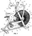
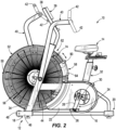
- FIGS. 1-3 depict a stationary exercise machine according to the present disclosure, which in the illustrated example is a stationary cycle 10.
- the stationary cycle has a supporting frame 12 that supports an adjustable seat 14 with respect to the ground.
- the supporting frame 12 has an axially elongated base member 16 and transversely elongated forward and rearward brace members 18, 20.
- a pedal housing 22 contains a pair of pedal members 24.
- Each pedal member 24 has a pedal 26 for supporting a user's foot and a crank arm 28 coupled to a laterally extending pedal axle 30.
- a seat pedestal 32 extends vertically upwardly from the pedal housing 22 and supports the seat 14.
- the position of the seat 14 can be adjusted relative to the seat pedestal 32 to accommodate users of different height, as is conventional and for example disclosed in U.S. Patent No.
- a forked, angularly extending support pillar 34 extends upwardly from the forward brace member 18 and has a support bracket 38 on its upper end for supporting a display panel, control panel, and/or the like 39, for use by the user sitting on the seat 14.
- a pair of handle members 40 are pivot-ably coupled to the support pillar 34, each having a handlebar 42 that can be manually grasped by the user sitting on the seat 14.
- the handle members 40 are manually pivotable back and forth relative to each other and to the support pillar 34.
- the type and configuration of the handlebar 42 can also vary from what is shown.
- a pair of stationary foot support pegs 44 are fixed to and laterally extend from the support pillar 34, and are for supporting a user's feet when the pedal members 24 are not being operated by the user.
- a pair of wheel brackets 46 extend forwardly from opposite ends of the forward brace member 18 and have wheels 48 facilitating transport of the stationary cycle 10 during periods of non-use.
- the supporting frame 12 can be pivoted forwardly about the wheel brackets 46 to thereby raise the rearward brace member 20 off the ground and allow the supporting frame 12 to be rolled along the ground via wheels 48.
- a resistance fan 50 is supported on the supporting frame 12, and particularly located within a housing 52, which in the illustrated example is a wire grate having a plurality of openings 54 (shown best in FIGS. 4-6 ) defined by gaps within the wire grate.
- the resistance fan 50 has a generally circular outer profile and rotates about a center axle 56.
- the resistance fan 50 is operably coupled to the pedal members 24 by for example gearing and/or belt(s) and/or chain(s) and/or the like (not shown) such that operating the pedal members 24 (i.e., pedaling the pedal members 24 with respect to the pedal axle 30) rotates the resistance fan 50 about the center axle 56.
- the resistance fan 50 is also operatively coupled to the handle members 40 by for example gearing and/or belt(s) and/or chain(s) and/or the like (not shown) such that operating the handlebars 42 (i.e., pushing and/or pulling the handlebars 42 back and forth with respect to the support pillar 34) rotates the resistance fan 50 about the center axle 56, all as is conventional.
- the resistance fan 50 has contours (e.g. ridges, plates, holes, slots, curvatures, etc.) such that when rotated, the resistance fan 50 encounters resistance from the surrounding air, which resistance in turn is applied to the user pedaling the pedal members 24 and/or operating the handle members 40, all as is conventional.
- the resistance fan 50 is configured to provide resistance to the user of the stationary cycle 10 via the pedal members 24 and/or handlebars 42, all as is conventional.
- the air that is encountered by the resistance fan 50 is forced outwardly away from the resistance fan 50 and towards the through the openings 54 in the housing 52.
- the particular contours of the resistance fan 50 can vary, examples of which are known in the art and for example disclosed in the above-referenced patents.
- a novel, movable shroud 58 is located on the housing 52, and particularly on a rearward side of the housing 52, between the seat 14 and the handle members 40.
- a fixed cowling (not shown) can be located on the housing 52, and particularly on the portions of the housing 52 located forwardly of the support pillar 34, and thus preventing flow of air through the housing 52 at the locations of the fixed cowling.
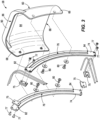
- the movable shroud 58 includes a generally U-shaped sleeve 60 disposed on the rear, radially outer perimeter 62 of the housing 52.
- the sleeve 60 has a body 64 and opposing first and second arms 66, 68 that together form the U-shape.
- the first and second arms 66, 68 are coupled to axially opposite side faces of the housing 52 via arcuate tracks 74.
- the arcuate tracks 74 are fixed to the opposing side faces via backing brackets 75 and fasteners 77.
- the arcuate tracks 74 have elongated slots 76 that generally follow the profile of the radially outer perimeter 62 of the housing 52.
- a pair of fasteners 80 extend through the first and second arms 66, 68 and are disposed in and configured to slide along the arcuate tracks 74, and thus facilitate sliding movement of the sleeve 60 along the arcuate tracks 74 and along the rear, radially outer perimeter 62 of the housing 52.
- Engagement between the fasteners 80 with the opposite ends 82, 84 of the slots 76 defines first and second extreme positions into which the shroud 58 is slide-able with respect to the housing 52.
- the sleeve 60 has a leading edge 86 and an opposite, trailing edge 88, and a handle 90 located proximate to the leading edge 86 and facilitating manual grasping and sliding of the sleeve 60 with respect to the housing 52 into and between the noted extreme positions.
- the plurality of openings 54 in the wire grate that are not covered by the noted fixed cowling thus define a total cross-sectional area through which the air flows through the housing 52.
- the plurality of openings 54 is defined, at least in part, along the radially outer perimeter 62 of the housing 52, which is along the housing 52 between the pedal members 24 and the handle members 40, such that air encountered by the resistance fan 50 is forced radially from the housing 52 and directed onto the user sitting on the seat 14. This forces air onto and cools the user sitting on the seat 14.
- Each opening 54 directs the air from the resistance fan 50 in a slightly different respective radial direction. A portion of the total cross-sectional area for flow of air through the housing 52 is blocked by the shroud 58.
- the total cross-sectional area of the housing 52 through which air can flow is a factor that determines the amount of resistance provided by the fan 50.
- the greater the cross-sectional area the less resistance provided by the fan 50, and vice versa.
- the shroud 58 is configured so as to be movable with respect to the plurality of openings 54 so as to redirect the air from the resistance fan 50 without changing the amount of resistance provided to the user of the stationary cycle 10.
- the trailing edge 88 uncovers a portion of the total cross-sectional area of the plurality of openings 54 as the leading edge 86 simultaneously covers an equal portion of the total cross-sectional area of the plurality of openings 54.
- the shroud 58 is movable with respect to the housing 52 into and between a plurality of positions; however in each position an equal portion of the air from the resistance fan 50 is blocked and/or redirected. This causes the total resistance provided by the resistance fan 50 to the user to remain unchanged during and after said movement.
- the shroud 58 As the shroud 58 is moved into and between the extreme positions defined by engagement between the tabs 80 and the ends 82, 84 of the arcuate tracks 74, the shroud 58 continuously covers an equal portion of the cross-sectional area, thus causing the resistance provided by the resistance fan 50 to remain unchanged. That is, in all positions along the radially outer perimeter 62 of the housing 52, the shroud 58 advantageously covers an equal portion of the total cross-sectional area, thus leaving the total resistance provided by the resistance fan 50 unchanged.
- FIG. 4 depicts another example of a shroud 58a according to the present disclosure.
- the shroud 58a instead of being coupled to the housing 52 via the above-described arcuate tracks 74, the shroud 58a has elongated first and second arms 66a, 68b that are pivot-ably coupled to the housing 52 and/or support pillar 34, and thus pivotable about a lateral pivot axis 92.
- An opening 94 is defined between the first and second arms 66a, 66b through which air from the resistance fan 50 can pass.
- the shroud 58a advantageously covers an equal portion of the total cross-sectional area, thus leaving the total resistance provided by the resistance fan 50 unchanged.
- FIG. 5 depicts another example of a shroud 58b according to the present disclosure.
- the shroud 58b differs from what is shown in FIGS. 1-3 in that it has a body 64 that is disposed inside of the housing 52.
- an elongated track 96 is formed through the radially outer perimeter 62 of the housing 52.
- the shroud 58b has a handle 90b that extends through the elongated track 96 and facilitates manual sliding of the shroud 58b along the interior of the radially outer perimeter 62 of the housing 52 into and between extreme first and second positions, all as described herein above.
- the shroud 58b advantageously covers an equal portion of the total cross-sectional area, thus leaving the total resistance provided by the resistance fan 50 unchanged.
- FIG. 6 depicts another example of a shroud 58a according to the present disclosure.
- Like reference numbers are used for like components shown in the example of FIGS 1-3 .
- an elongated track 96 is formed through the radially outer perimeter 62 of the housing 52.
- the shroud 58c differs from what is shown in FIG. 5 , in that the body 64 is disposed outside of the housing 52 and is slide-ably engaged with the elongated track 96 (via for example a pin or tab, not shown, that extends through the elongated track 96 in a relationship similar to the engagement between the handle 90b shown in FIG. 5 ).
- the shroud 58c has a handle 90c that facilitates manual sliding of the shroud 58c along the exterior of the radially outer perimeter 62 of the housing 52 into and between extreme first and second positions, all as described herein above. In all positions along the radially outer perimeter 62 of the housing 52, the shroud 58c advantageously covers an equal portion of the total cross-sectional area, thus leaving the total resistance provided by the resistance fan 50 unchanged.
- the stationary cycle 10 can include a user-operable control unit 39, such as disclosed in U.S. Patent No. 10071286 .
- the user-operable control unit can for example be mounted on the support bracket 38 and be programmed to automatically move the shroud 58, 58a-58c, via for example an electric motor, hydraulic actuator, or any other similar known actuation device for moving components on an exercise machine.
- Such a mechanism can be powered by electricity, for example as disclosed in U.S. Patent No. 9942718 .
- Automatically controlling movement of the shroud 58 can be based on user inputs to the noted user-operable control unit and/or programmed exercise routines run by the control unit, and/or based on current characteristics of the user (e.g., the user's heart-rate) as sensed by biometric sensors, all as well known in the art, one example being disclosed in U.S. Patent No. 8082029 .
- the present disclosure thus advantageously provides a novel exercise cycle having supporting frame; pedals for performing a cycling exercise motion relative to the supporting frame; and a resistance fan operatively coupled to the pedals such that performance of the cycling exercise motion causes rotation of the resistance fan, which thereby provides an amount of resistance to the cycling exercise motion via the pedals.
- a housing encloses the resistance fan and having a plurality of openings through which air from the resistance fan is directed towards a user of the exercise cycle.
- a shroud is located on the housing and is movable with respect to the plurality of openings so as to redirect the air from the resistance fan without changing the amount of resistance provided to the user of the exercise cycle.
Landscapes
- Health & Medical Sciences (AREA)
- Engineering & Computer Science (AREA)
- General Health & Medical Sciences (AREA)
- Physical Education & Sports Medicine (AREA)
- Cardiology (AREA)
- Vascular Medicine (AREA)
- General Engineering & Computer Science (AREA)
- Mechanical Engineering (AREA)
- Life Sciences & Earth Sciences (AREA)
- Biophysics (AREA)
- Orthopedic Medicine & Surgery (AREA)
- Structures Of Non-Positive Displacement Pumps (AREA)
- Professional, Industrial, Or Sporting Protective Garments (AREA)
Description
- The present disclosure relates to exercise machines, for example stationary cycles having a resistance fan that directs air for cooling a user.
-
U.S. Patent No. 4,589,656 discloses a device for aerobic exercise having an elongate frame, a housing enclosing the frame, a stress imposing pedal-driven fan carried by one end portion of the frame and a user supporting and positioning seat carried by the other end portion of the frame opposite the fan. The positioning seat has a seat portion inclined from front to rear at a predetermined acute angle to the horizontal, and a backrest portion inclined at a predetermined acute angle to the vertical, with at least the backrest portion having ventilation openings therein which communicate with the front and rear surfaces of the backrest portion. Air passages communicate with the discharge side of the fan and also with the ventilation openings in the backrest portion and serve for directing air discharged by the fan through the ventilation openings to the forward surface of the backrest portion and outwardly therefrom whereby the air cools the user and substantially increases the user's comfort, particularly during long periods of use. -
U.S. Patent No. 4,932,650 discloses an exercise cycle having a frame, a pedal actuated gear arrangement and an impeller, mechanically associated with that gearing arrangement. The impeller is housed within a chamber defined within a housing mounted on the frame. The chamber includes an inlet opening for introducing a stream of environmental air into the chamber and an outlet opening adapted for directing a flow of pressurized air generated by the impeller's rotation over the body of the user. -
U.S. Patent No. 5,920,212 discloses an exercise cycle including a frame having a front wheel assembly and handlebars. The front wheel assembly includes a fan wheel having side plates one of which has an intake port, and an intake assembly around the intake port, the intake assembly having openings which may be opened and closed. By opening and closing the intake openings, the resistance of the wheel to the air can be varied without changing the rotational rate of the wheel. The handlebars of the exercise cycle are pivotally connected to the cycle intermediate their ends. The lower ends of the handlebars are pivotally connected to a cam arm which is removably connected to the shaft to which the pedal is mounted. By connecting or disconnecting the cam arm to or from the pedal shaft, the handlebars can be selectively moved between a stationary mode and a mode in which the handlebars reciprocate between forward and backward positions. -
U.S. Patent No. 6,960,156 (following the publicationUS 2003-0216227 A1 ) discloses a device for directing a concentrated airflow at the user of an air resisted exercise machine. The cowling is constructed from either a semi-rigid material or low-porosity fabric and can be removably attached to the cage covering the fan type blades usually associated with such machines. Various means can be used to attach the device to the cage, one means being the use of elastic cords routed through welts. In use, the device of the current invention directs air at the user of the machine. The device is lightweight and portable, and a user can carry the device along for use on machines in a variety of places. Moreover,U.S. Patent No. 4,932,650 discloses an exercise cycle having a frame, a pedal actuated gear arrangement and an impeller, mechanically associated with that gearing arrangement, is disclosed. The impeller is housed within a chamber defined within a housing mounted on the frame. The chamber includes an inlet opening for introducing a stream of environmental air into the chamber and an outlet opening adapted for directing a flow of pressurized air generated by the impeller's rotation over the body of the user. - This Summary is provided to introduce a selection of concepts that are further described herein below in the Detailed Description. This Summary is not intended to identify key or essential features of the claimed subject matter, nor is it intended to be used as an aid in limiting scope of the claimed subject matter. In certain examples disclosed herein: an exercise machine has a supporting frame; a resistance fan on the supporting frame, the resistance fan being configured to provide an amount of resistance to a user of the exercise machine; a housing enclosing the resistance fan, the housing having a plurality of openings through which air from the resistance fan is directed towards the user of the exercise machine; and a shroud on the housing. The shroud is movable into a plurality of positions with respect to the housing and the plurality of openings. The plurality of openings defines a total cross-sectional area through which the air, upon use of the machine, flows through the housing. In each of the plurality of positions the shroud covers an equal portion of the total cross-sectional area so that an equal portion of the air from the resistance fan is redirected, whereby air is redirected from the resistance fan without changing the amount of resistance provided to the user of the exercise machine. The shroud is located on a rear side of the housing, the rear side of the housing being towards the user of the exercise machine.
- Optionally, the shroud is movable along the housing from an extreme first position to an opposite, extreme second position, and as the shroud is moved into and between the extreme first position and the opposite, extreme second position, the shroud continuously covers an equal portion of the cross-sectional area.
- Optionally, the resistance fan is circular and has an outer diameter, and the housing comprises a radially outer perimeter, and the plurality of openings are disposed along the radially outer perimeter.
- Optionally, the air, upon use of the machine, flows from the resistance fan through each opening in the plurality of openings in a different direction, respectively.
- Optionally, the shroud comprises a sleeve that is slide-able along the radially outer perimeter of the housing.
- Optionally, the sleeve comprises a leading edge and an opposite, trailing edge, and as the shroud is movable along the radially outer perimeter of the housing the trailing edge to uncover a portion of the total cross-sectional area of the plurality of openings as the leading edge covers an equal portion of the total cross-sectional area of the plurality of openings.
- Optionally, the sleeve is disposed outside of the housing.
- Optionally, the sleeve comprises first and second arms that together form a U-shape.
- Optionally, the resistance fan is rotatable about a center axle, and the housing comprises axially opposite side faces, and the first and second arms are coupled to the axially opposite side faces, respectively.
- Optionally, the exercise machine further comprises arcuate tracks on the axially opposite side faces, and the first and second arms are engaged with and slide along the arcuate tracks, respectively.
- Optionally, the sleeve is disposed on the inside of the housing.
- Optionally, the housing comprises a wire grate and the plurality of openings are defined by gaps within the wire grate.
- Optionally, the exercise machine is an exercise cycle.
- Examples of exercise machines are herein disclosed with reference to the following drawing figures. The same numbers are used throughout to reference like features and components.
-
FIG. 1 is a perspective view of an exercise machine according to the present disclosure, which in the illustrated example is a stationary cycle. -
FIG. 2 is a side view of the stationary cycle. -
FIG. 3 is an exploded view of a shroud that is configured to redirect air from a resistance fan of the stationary cycle. -
FIG. 4 is a second example of the shroud on the housing of the resistance fan. -
FIG. 5 is a third example of the shroud on the housing of the resistance fan. -
FIG. 6 is a fourth example of the shroud on the housing of the resistance fan. - Through research and development, the present inventors have determined that conventional stationary exercise machines having resistance fans do not provide the user with the ability to change a flow of air contacting them during use without also modifying the level of resistance provided by the resistance fan. In particular, the present inventors realize that the total surface area of the fan housing through which the air can flow will affect the resistance encountered by the fan. The prior art mentioned herein above allows the user to change the direction of airflow through the fan housing; however only in arrangements that also change the noted cross-sectional area and thus the resistance. This is disadvantageous. Upon this realization, the present inventors endeavored to provide an exercise machine, in particular a stationary exercise machine, that overcomes these disadvantages of the prior art. The present disclosure is a result of these efforts.
-
FIGS. 1-3 depict a stationary exercise machine according to the present disclosure, which in the illustrated example is astationary cycle 10. The stationary cycle has a supportingframe 12 that supports anadjustable seat 14 with respect to the ground. The supportingframe 12 has an axiallyelongated base member 16 and transversely elongated forward and rearwardbrace members pedal housing 22 contains a pair ofpedal members 24. Eachpedal member 24 has apedal 26 for supporting a user's foot and acrank arm 28 coupled to a laterally extendingpedal axle 30. Aseat pedestal 32 extends vertically upwardly from thepedal housing 22 and supports theseat 14. Optionally, the position of theseat 14 can be adjusted relative to theseat pedestal 32 to accommodate users of different height, as is conventional and for example disclosed inU.S. Patent No. 8496297 . A forked, angularly extendingsupport pillar 34 extends upwardly from theforward brace member 18 and has a support bracket 38 on its upper end for supporting a display panel, control panel, and/or the like 39, for use by the user sitting on theseat 14. A pair ofhandle members 40 are pivot-ably coupled to thesupport pillar 34, each having ahandlebar 42 that can be manually grasped by the user sitting on theseat 14. Thehandle members 40 are manually pivotable back and forth relative to each other and to thesupport pillar 34. The type and configuration of thehandlebar 42 can also vary from what is shown. Optionally, a pair of stationary foot support pegs 44 are fixed to and laterally extend from thesupport pillar 34, and are for supporting a user's feet when thepedal members 24 are not being operated by the user. A pair ofwheel brackets 46 extend forwardly from opposite ends of theforward brace member 18 and havewheels 48 facilitating transport of thestationary cycle 10 during periods of non-use. As is conventional, the supportingframe 12 can be pivoted forwardly about thewheel brackets 46 to thereby raise therearward brace member 20 off the ground and allow the supportingframe 12 to be rolled along the ground viawheels 48. - A
resistance fan 50 is supported on the supportingframe 12, and particularly located within ahousing 52, which in the illustrated example is a wire grate having a plurality of openings 54 (shown best inFIGS. 4-6 ) defined by gaps within the wire grate. Theresistance fan 50 has a generally circular outer profile and rotates about acenter axle 56. Theresistance fan 50 is operably coupled to thepedal members 24 by for example gearing and/or belt(s) and/or chain(s) and/or the like (not shown) such that operating the pedal members 24 (i.e., pedaling thepedal members 24 with respect to the pedal axle 30) rotates theresistance fan 50 about thecenter axle 56. Optionally theresistance fan 50 is also operatively coupled to thehandle members 40 by for example gearing and/or belt(s) and/or chain(s) and/or the like (not shown) such that operating the handlebars 42 (i.e., pushing and/or pulling thehandlebars 42 back and forth with respect to the support pillar 34) rotates theresistance fan 50 about thecenter axle 56, all as is conventional. - Referring briefly to
FIGS. 4-6 , theresistance fan 50 has contours (e.g. ridges, plates, holes, slots, curvatures, etc.) such that when rotated, theresistance fan 50 encounters resistance from the surrounding air, which resistance in turn is applied to the user pedaling thepedal members 24 and/or operating thehandle members 40, all as is conventional. Thus, theresistance fan 50 is configured to provide resistance to the user of thestationary cycle 10 via thepedal members 24 and/orhandlebars 42, all as is conventional. The air that is encountered by theresistance fan 50 is forced outwardly away from theresistance fan 50 and towards the through theopenings 54 in thehousing 52. The particular contours of theresistance fan 50 can vary, examples of which are known in the art and for example disclosed in the above-referenced patents. The manner in which theresistance fan 50 is operably coupled to thepedal members 24 can vary, examples of which are known in the art and for example disclosed in the above-referenced patents. The manner in which theresistance fan 50 is operably coupled to thehandle members 40 is conventional and can vary. Examples of conventional stationary cycles are disclosed inU.S. Patent No. 6913560 . - Referring now to
FIGS. 1-3 , according to the present disclosure, a novel,movable shroud 58 is located on thehousing 52, and particularly on a rearward side of thehousing 52, between theseat 14 and thehandle members 40. Optionally, a fixed cowling (not shown) can be located on thehousing 52, and particularly on the portions of thehousing 52 located forwardly of thesupport pillar 34, and thus preventing flow of air through thehousing 52 at the locations of the fixed cowling. In the example shown inFIG. 3 , themovable shroud 58 includes a generallyU-shaped sleeve 60 disposed on the rear, radiallyouter perimeter 62 of thehousing 52. Thesleeve 60 has abody 64 and opposing first andsecond arms second arms housing 52 via arcuate tracks 74. The arcuate tracks 74 are fixed to the opposing side faces viabacking brackets 75 andfasteners 77. The arcuate tracks 74 have elongatedslots 76 that generally follow the profile of the radiallyouter perimeter 62 of thehousing 52. A pair offasteners 80 extend through the first andsecond arms arcuate tracks 74, and thus facilitate sliding movement of thesleeve 60 along thearcuate tracks 74 and along the rear, radiallyouter perimeter 62 of thehousing 52. Engagement between thefasteners 80 with the opposite ends 82, 84 of theslots 76 defines first and second extreme positions into which theshroud 58 is slide-able with respect to thehousing 52. Thesleeve 60 has aleading edge 86 and an opposite, trailingedge 88, and ahandle 90 located proximate to the leadingedge 86 and facilitating manual grasping and sliding of thesleeve 60 with respect to thehousing 52 into and between the noted extreme positions. - The plurality of
openings 54 in the wire grate that are not covered by the noted fixed cowling thus define a total cross-sectional area through which the air flows through thehousing 52. The plurality ofopenings 54 is defined, at least in part, along the radiallyouter perimeter 62 of thehousing 52, which is along thehousing 52 between thepedal members 24 and thehandle members 40, such that air encountered by theresistance fan 50 is forced radially from thehousing 52 and directed onto the user sitting on theseat 14. This forces air onto and cools the user sitting on theseat 14. Eachopening 54 directs the air from theresistance fan 50 in a slightly different respective radial direction. A portion of the total cross-sectional area for flow of air through thehousing 52 is blocked by theshroud 58. The total cross-sectional area of thehousing 52 through which air can flow is a factor that determines the amount of resistance provided by thefan 50. The greater the cross-sectional area, the less resistance provided by thefan 50, and vice versa. Advantageously, theshroud 58 is configured so as to be movable with respect to the plurality ofopenings 54 so as to redirect the air from theresistance fan 50 without changing the amount of resistance provided to the user of thestationary cycle 10. In particular, as theshroud 58 is moved along the radiallyouter perimeter 62 of thehousing 52, the trailingedge 88 uncovers a portion of the total cross-sectional area of the plurality ofopenings 54 as the leadingedge 86 simultaneously covers an equal portion of the total cross-sectional area of the plurality ofopenings 54. In other words, theshroud 58 is movable with respect to thehousing 52 into and between a plurality of positions; however in each position an equal portion of the air from theresistance fan 50 is blocked and/or redirected. This causes the total resistance provided by theresistance fan 50 to the user to remain unchanged during and after said movement. As theshroud 58 is moved into and between the extreme positions defined by engagement between thetabs 80 and theends arcuate tracks 74, theshroud 58 continuously covers an equal portion of the cross-sectional area, thus causing the resistance provided by theresistance fan 50 to remain unchanged. That is, in all positions along the radiallyouter perimeter 62 of thehousing 52, theshroud 58 advantageously covers an equal portion of the total cross-sectional area, thus leaving the total resistance provided by theresistance fan 50 unchanged. -
FIG. 4 depicts another example of ashroud 58a according to the present disclosure. Like reference numbers are used for like components shown in the example ofFIGS 1-3 . In this example, instead of being coupled to thehousing 52 via the above-describedarcuate tracks 74, theshroud 58a has elongated first andsecond arms housing 52 and/orsupport pillar 34, and thus pivotable about a lateral pivot axis 92. Anopening 94 is defined between the first andsecond arms 66a, 66b through which air from theresistance fan 50 can pass. In all positions along the radiallyouter perimeter 62 of thehousing 52, theshroud 58a advantageously covers an equal portion of the total cross-sectional area, thus leaving the total resistance provided by theresistance fan 50 unchanged. -
FIG. 5 depicts another example of ashroud 58b according to the present disclosure. Like reference numbers are used for like components shown in the example ofFIGS 1-3 . Theshroud 58b differs from what is shown inFIGS. 1-3 in that it has abody 64 that is disposed inside of thehousing 52. In this example, anelongated track 96 is formed through the radiallyouter perimeter 62 of thehousing 52. Theshroud 58b has ahandle 90b that extends through theelongated track 96 and facilitates manual sliding of theshroud 58b along the interior of the radiallyouter perimeter 62 of thehousing 52 into and between extreme first and second positions, all as described herein above. In all positions along the radiallyouter perimeter 62 of thehousing 52, theshroud 58b advantageously covers an equal portion of the total cross-sectional area, thus leaving the total resistance provided by theresistance fan 50 unchanged. -
FIG. 6 depicts another example of ashroud 58a according to the present disclosure. Like reference numbers are used for like components shown in the example ofFIGS 1-3 . Like the example shown inFIG. 5 , anelongated track 96 is formed through the radiallyouter perimeter 62 of thehousing 52. Theshroud 58c differs from what is shown inFIG. 5 , in that thebody 64 is disposed outside of thehousing 52 and is slide-ably engaged with the elongated track 96 (via for example a pin or tab, not shown, that extends through theelongated track 96 in a relationship similar to the engagement between thehandle 90b shown inFIG. 5 ). Theshroud 58c has ahandle 90c that facilitates manual sliding of theshroud 58c along the exterior of the radiallyouter perimeter 62 of thehousing 52 into and between extreme first and second positions, all as described herein above. In all positions along the radiallyouter perimeter 62 of thehousing 52, theshroud 58c advantageously covers an equal portion of the total cross-sectional area, thus leaving the total resistance provided by theresistance fan 50 unchanged. - In other examples, the
stationary cycle 10 can include a user-operable control unit 39, such as disclosed inU.S. Patent No. 10071286 shroud U.S. Patent No. 9942718 shroud 58 can be based on user inputs to the noted user-operable control unit and/or programmed exercise routines run by the control unit, and/or based on current characteristics of the user (e.g., the user's heart-rate) as sensed by biometric sensors, all as well known in the art, one example being disclosed inU.S. Patent No. 8082029 . - The present disclosure thus advantageously provides a novel exercise cycle having supporting frame; pedals for performing a cycling exercise motion relative to the supporting frame; and a resistance fan operatively coupled to the pedals such that performance of the cycling exercise motion causes rotation of the resistance fan, which thereby provides an amount of resistance to the cycling exercise motion via the pedals. A housing encloses the resistance fan and having a plurality of openings through which air from the resistance fan is directed towards a user of the exercise cycle. A shroud is located on the housing and is movable with respect to the plurality of openings so as to redirect the air from the resistance fan without changing the amount of resistance provided to the user of the exercise cycle.
- In the present description, certain terms have been used for brevity, clearness and understanding. No unnecessary limitations are to be implied therefrom beyond the requirement of the prior art because such terms are used for descriptive purposes only and are intended to be broadly construed. The different apparatuses described herein may be used alone or in combination with other apparatuses. The invention is defined by the appended claims.
Claims (13)
- An exercise machine (10) comprising:- a supporting frame (12);- a resistance fan (50) on the supporting frame (12), the resistance fan (50) being configured to provide an amount of resistance to a user of the exercise machine (10);- a housing (52) enclosing the resistance fan (50), the housing (52) having a plurality of openings (54) through which air from the resistance fan (50) is directed towards the user of the exercise machine (10);- a shroud (58, 58a, 58b, 58c) on the housing (52), the shroud (58, 58a, 58b, 58c) being movable into a plurality of positions with respect to the housing (52) and the plurality of openings (54), wherein the plurality of openings (54) defines a total cross-sectional area through which the air, upon use of the machine, flows through the housing (52), and wherein in each of the plurality of positions the shroud (58, 58a, 58b, 58c) covers an equal portion of the total cross-sectional area so that an equal portion of the air from the resistance fan is redirected, whereby air is redirected from the resistance fan (50) without changing the amount of resistance provided to the user of the exercise machine (10), characterized in that- the shroud (58, 58a, 58b, 58c) is located on a rear side of the housing (52), the rear side of the housing (52) being towards the user of the exercise machine (10).
- The exercise machine (10) according to claim 1, wherein the shroud (58, 58a, 58b, 58c) is movable along the housing (52) from an extreme first position to an opposite, extreme second position, and wherein as the shroud is moved into and between the extreme first position and the opposite, extreme second position, the shroud (58, 58a, 58b, 58c) continuously covers an equal portion of the cross-sectional area.
- The exercise machine (10) according to any one of the preceding claims, wherein the resistance fan (50) is circular and has an outer diameter, and wherein the housing (52) comprises a radially outer perimeter (62), and wherein the plurality of openings (52) are disposed along the radially outer perimeter (62).
- The exercise machine (10) according to claim 3, wherein the air, upon use of the machine, flows from the resistance fan (50) through each opening (54) in the plurality of openings in a different direction, respectively.
- The exercise machine according to claim 3 or 4, wherein the shroud (58, 58a) comprises a sleeve (60) that is slide-able along the radially outer perimeter (62) of the housing (52).
- The exercise machine (10) according to claim 5, wherein the sleeve (60) comprises a leading edge (86) and an opposite, trailing edge (88), and wherein as the shroud (58, 58a) is movable along the radially outer perimeter (62) of the housing (52) the trailing edge (86) to uncover a portion of the total cross-sectional area of the plurality of openings (54) as the leading edge (86) covers an equal portion of the total cross-sectional area of the plurality of openings (54).
- The exercise machine (10) according to claim 6, wherein the sleeve (60) is disposed outside of the housing (52).
- The exercise machine (10) according to claim 6 or 7, wherein the sleeve (60) comprises first and second arms (66, 68) that together form a U-shape.
- The exercise machine (10) according to claim 8, wherein the resistance fan (50) is rotatable about a center axle (56), and wherein the housing (52) comprises axially opposite side faces, and wherein the first and second arms (66, 68) are coupled to the axially opposite side faces, respectively.
- The exercise machine (10) according to claim 9, further comprising arcuate tracks (74) on the axially opposite side faces, and wherein the first and second arms (66, 68) are engaged with and slide along the arcuate tracks (74), respectively.
- The exercise machine (10) according to claim 6, wherein the sleeve (60) is disposed on the inside of the housing (52).
- The exercise machine according to any one of the preceding claims, wherein the housing (52) comprises a wire grate and wherein the plurality of openings (54) are defined by gaps within the wire grate.
- An exercise machine (10) according to any one of the preceding claims, wherein the exercise machine (10) is an exercise cycle.
Applications Claiming Priority (1)
| Application Number | Priority Date | Filing Date | Title |
|---|---|---|---|
| US16/595,679 US11161003B2 (en) | 2019-10-08 | 2019-10-08 | Exercise machines having a resistance fan that directs air for cooling a user |
Publications (3)
| Publication Number | Publication Date |
|---|---|
| EP3804820A1 EP3804820A1 (en) | 2021-04-14 |
| EP3804820C0 EP3804820C0 (en) | 2024-11-27 |
| EP3804820B1 true EP3804820B1 (en) | 2024-11-27 |
Family
ID=72852378
Family Applications (1)
| Application Number | Title | Priority Date | Filing Date |
|---|---|---|---|
| EP20199567.7A Active EP3804820B1 (en) | 2019-10-08 | 2020-10-01 | Exercise machines having a resistance fan that directs air for cooling a user |
Country Status (4)
| Country | Link |
|---|---|
| US (1) | US11161003B2 (en) |
| EP (1) | EP3804820B1 (en) |
| CN (1) | CN112628167B (en) |
| TW (1) | TWI842938B (en) |
Families Citing this family (8)
| Publication number | Priority date | Publication date | Assignee | Title |
|---|---|---|---|---|
| USD858663S1 (en) * | 2018-08-01 | 2019-09-03 | Coulter Ventures, LLC | Exercise bike |
| USD861809S1 (en) * | 2018-08-01 | 2019-10-01 | Coulter Ventures, LLC | Fan |
| US11161003B2 (en) * | 2019-10-08 | 2021-11-02 | Life Fitness, Llc | Exercise machines having a resistance fan that directs air for cooling a user |
| USD1010038S1 (en) * | 2021-08-26 | 2024-01-02 | Lifecore Fitness, Inc. | Exercise apparatus |
| USD1020935S1 (en) * | 2021-08-26 | 2024-04-02 | Lifecore Fitness, Inc. | Exercise apparatus |
| USD1010039S1 (en) * | 2021-08-26 | 2024-01-02 | Lifecore Fitness, Inc. | Exercise apparatus |
| US12343589B1 (en) | 2023-02-17 | 2025-07-01 | Daniel Bishop | Treadmill with calibrated airflow |
| AU2023442492A1 (en) * | 2023-04-07 | 2025-11-20 | Coulter Ventures, LLC | Exercise bike |
Family Cites Families (23)
| Publication number | Priority date | Publication date | Assignee | Title |
|---|---|---|---|---|
| US4589656A (en) | 1984-11-07 | 1986-05-20 | Nautilus Sports/Medical Industries, Inc. | Aerobic exercise device for increased user comfort |
| US4743011A (en) | 1986-07-07 | 1988-05-10 | Calvin Coffey | Exercise rowing machine |
| US4932650A (en) | 1989-01-13 | 1990-06-12 | Proform Fitness Products, Inc. | Semi-recumbent exercise cycle |
| US5048824A (en) * | 1990-07-11 | 1991-09-17 | Ya Te Industry Co., Ltd. | Air resistance excerciser with negative ion generator |
| US5290212A (en) * | 1991-09-03 | 1994-03-01 | Roadmaster Corporation | Exercise cycle |
| KR100194761B1 (en) | 1996-10-02 | 1999-06-15 | 이계철 | Controlled Continuous Ramp Converter |
| US20020137601A1 (en) | 2001-03-23 | 2002-09-26 | Tobias Andrew J. | Exercise device |
| US6913560B2 (en) | 2001-09-26 | 2005-07-05 | Brunswick Corporation | Stationary bike |
| US6960156B2 (en) | 2002-05-16 | 2005-11-01 | Paul Smith | Device for directing air flow at users of air resisted exercise machines |
| NL1024967C1 (en) * | 2003-12-08 | 2004-01-13 | Flow Fitness B V | Flywheel device for altering resistance level in air braked exercise machines, has flow of outgoing air regulated by sliding valve |
| US8021278B2 (en) | 2007-03-29 | 2011-09-20 | Brunswick Corporation | Seat mechanisms |
| US8082029B2 (en) | 2007-05-17 | 2011-12-20 | Brunswick Corporation | Adjustable sensors for use with exercise apparatus |
| US20100227542A1 (en) * | 2009-03-09 | 2010-09-09 | Richard Goldmann | Apparatus for cooling an exerciser for use with an exercise machine |
| US9579534B2 (en) | 2012-09-14 | 2017-02-28 | Brunswick Corporation | Methods and apparatus to power an exercise machine |
| CN204380089U (en) * | 2015-01-16 | 2015-06-10 | 中山生动力健身器材有限公司 | Pull rod exercise bicycle |
| TWM524735U (en) * | 2016-02-18 | 2016-07-01 | 必艾奇亞洲有限公司 | Treadmill |
| US10493311B2 (en) | 2016-03-23 | 2019-12-03 | Paradigm Health and Wellness | Adjustable air bike fan blades |
| US10071286B1 (en) | 2016-03-24 | 2018-09-11 | Brunswick Corporation | Systems and methods for determining and indicating a desired corrective change in exercise technique |
| US10300321B2 (en) * | 2017-03-09 | 2019-05-28 | Great Fitness Industrial Co., Ltd. | Exercise bicycle configured to provide fan-based resistance and fan wheel thereof |
| CN207822374U (en) * | 2018-01-29 | 2018-09-07 | 上海小莫网络科技有限公司 | A kind of flywheel structure and dynamic windage rowing machine of air quantity dual regulation |
| US10155132B2 (en) | 2018-04-26 | 2018-12-18 | Coulter Ventures Llc | Exercise bike |
| TWM579540U (en) * | 2018-12-26 | 2019-06-21 | 蔡育倫 | Treadmill with air blowing device |
| US11161003B2 (en) * | 2019-10-08 | 2021-11-02 | Life Fitness, Llc | Exercise machines having a resistance fan that directs air for cooling a user |
-
2019
- 2019-10-08 US US16/595,679 patent/US11161003B2/en active Active
-
2020
- 2020-08-03 TW TW109126184A patent/TWI842938B/en active
- 2020-09-27 CN CN202011034928.3A patent/CN112628167B/en active Active
- 2020-10-01 EP EP20199567.7A patent/EP3804820B1/en active Active
Also Published As
| Publication number | Publication date |
|---|---|
| EP3804820A1 (en) | 2021-04-14 |
| US11161003B2 (en) | 2021-11-02 |
| TWI842938B (en) | 2024-05-21 |
| CN112628167B (en) | 2026-03-13 |
| EP3804820C0 (en) | 2024-11-27 |
| TW202114757A (en) | 2021-04-16 |
| CN112628167A (en) | 2021-04-09 |
| US20210101042A1 (en) | 2021-04-08 |
Similar Documents
| Publication | Publication Date | Title |
|---|---|---|
| US11161003B2 (en) | Exercise machines having a resistance fan that directs air for cooling a user | |
| US5897460A (en) | Dual action air resistance treadmill | |
| EP3827885B1 (en) | Drop-in pivot configuration for stationary bike | |
| TWI573611B (en) | Elliptical exercise machine with an adjustable connection | |
| AU2014232303B2 (en) | Exercise machine | |
| US4589656A (en) | Aerobic exercise device for increased user comfort | |
| US5290212A (en) | Exercise cycle | |
| US8262163B2 (en) | Upholstered recliner chair with an adjustable backrest padding | |
| TWI755539B (en) | Exercise machine | |
| JP5482291B2 (en) | Lawn mower | |
| WO2021195773A1 (en) | Household appliance having an improved fan and motor assembly and fan and motor assembly for same | |
| US20240335699A1 (en) | Exercise Bike | |
| EP2324888B1 (en) | Stationary exercise apparatus | |
| CN221412109U (en) | Double-resistance adjustable rowing machine | |
| US20250257738A1 (en) | Household appliance having an improved fan and motor assembly and fan and motor assembly for same | |
| CN220365751U (en) | Hair drier | |
| CN224029224U (en) | Underwater bicycle | |
| HK1220658B (en) | Exercise machine | |
| JPH0856461A (en) | Mobile device for semimobile type plucking machine | |
| TWM510767U (en) | Synchronous crank type mini elliptical machine |
Legal Events
| Date | Code | Title | Description |
|---|---|---|---|
| PUAI | Public reference made under article 153(3) epc to a published international application that has entered the european phase |
Free format text: ORIGINAL CODE: 0009012 |
|
| STAA | Information on the status of an ep patent application or granted ep patent |
Free format text: STATUS: THE APPLICATION HAS BEEN PUBLISHED |
|
| AK | Designated contracting states |
Kind code of ref document: A1 Designated state(s): AL AT BE BG CH CY CZ DE DK EE ES FI FR GB GR HR HU IE IS IT LI LT LU LV MC MK MT NL NO PL PT RO RS SE SI SK SM TR |
|
| AX | Request for extension of the european patent |
Extension state: BA ME |
|
| STAA | Information on the status of an ep patent application or granted ep patent |
Free format text: STATUS: REQUEST FOR EXAMINATION WAS MADE |
|
| 17P | Request for examination filed |
Effective date: 20211012 |
|
| RBV | Designated contracting states (corrected) |
Designated state(s): AL AT BE BG CH CY CZ DE DK EE ES FI FR GB GR HR HU IE IS IT LI LT LU LV MC MK MT NL NO PL PT RO RS SE SI SK SM TR |
|
| P01 | Opt-out of the competence of the unified patent court (upc) registered |
Effective date: 20230524 |
|
| STAA | Information on the status of an ep patent application or granted ep patent |
Free format text: STATUS: EXAMINATION IS IN PROGRESS |
|
| 17Q | First examination report despatched |
Effective date: 20230810 |
|
| GRAP | Despatch of communication of intention to grant a patent |
Free format text: ORIGINAL CODE: EPIDOSNIGR1 |
|
| STAA | Information on the status of an ep patent application or granted ep patent |
Free format text: STATUS: GRANT OF PATENT IS INTENDED |
|
| INTG | Intention to grant announced |
Effective date: 20240515 |
|
| GRAS | Grant fee paid |
Free format text: ORIGINAL CODE: EPIDOSNIGR3 |
|
| GRAA | (expected) grant |
Free format text: ORIGINAL CODE: 0009210 |
|
| STAA | Information on the status of an ep patent application or granted ep patent |
Free format text: STATUS: THE PATENT HAS BEEN GRANTED |
|
| AK | Designated contracting states |
Kind code of ref document: B1 Designated state(s): AL AT BE BG CH CY CZ DE DK EE ES FI FR GB GR HR HU IE IS IT LI LT LU LV MC MK MT NL NO PL PT RO RS SE SI SK SM TR |
|
| REG | Reference to a national code |
Ref country code: GB Ref legal event code: FG4D |
|
| REG | Reference to a national code |
Ref country code: CH Ref legal event code: EP |
|
| REG | Reference to a national code |
Ref country code: IE Ref legal event code: FG4D |
|
| REG | Reference to a national code |
Ref country code: DE Ref legal event code: R096 Ref document number: 602020041954 Country of ref document: DE |
|
| U01 | Request for unitary effect filed |
Effective date: 20241217 |
|
| P04 | Withdrawal of opt-out of the competence of the unified patent court (upc) registered |
Free format text: CASE NUMBER: APP_649/2025 Effective date: 20250108 |
|
| U07 | Unitary effect registered |
Designated state(s): AT BE BG DE DK EE FI FR IT LT LU LV MT NL PT RO SE SI Effective date: 20250110 |
|
| PG25 | Lapsed in a contracting state [announced via postgrant information from national office to epo] |
Ref country code: HR Free format text: LAPSE BECAUSE OF FAILURE TO SUBMIT A TRANSLATION OF THE DESCRIPTION OR TO PAY THE FEE WITHIN THE PRESCRIBED TIME-LIMIT Effective date: 20241127 Ref country code: IS Free format text: LAPSE BECAUSE OF FAILURE TO SUBMIT A TRANSLATION OF THE DESCRIPTION OR TO PAY THE FEE WITHIN THE PRESCRIBED TIME-LIMIT Effective date: 20250327 |
|
| PG25 | Lapsed in a contracting state [announced via postgrant information from national office to epo] |
Ref country code: ES Free format text: LAPSE BECAUSE OF FAILURE TO SUBMIT A TRANSLATION OF THE DESCRIPTION OR TO PAY THE FEE WITHIN THE PRESCRIBED TIME-LIMIT Effective date: 20241127 |
|
| PG25 | Lapsed in a contracting state [announced via postgrant information from national office to epo] |
Ref country code: NO Free format text: LAPSE BECAUSE OF FAILURE TO SUBMIT A TRANSLATION OF THE DESCRIPTION OR TO PAY THE FEE WITHIN THE PRESCRIBED TIME-LIMIT Effective date: 20250227 |
|
| PG25 | Lapsed in a contracting state [announced via postgrant information from national office to epo] |
Ref country code: GR Free format text: LAPSE BECAUSE OF FAILURE TO SUBMIT A TRANSLATION OF THE DESCRIPTION OR TO PAY THE FEE WITHIN THE PRESCRIBED TIME-LIMIT Effective date: 20250228 |
|
| PG25 | Lapsed in a contracting state [announced via postgrant information from national office to epo] |
Ref country code: PL Free format text: LAPSE BECAUSE OF FAILURE TO SUBMIT A TRANSLATION OF THE DESCRIPTION OR TO PAY THE FEE WITHIN THE PRESCRIBED TIME-LIMIT Effective date: 20241127 |
|
| PG25 | Lapsed in a contracting state [announced via postgrant information from national office to epo] |
Ref country code: RS Free format text: LAPSE BECAUSE OF FAILURE TO SUBMIT A TRANSLATION OF THE DESCRIPTION OR TO PAY THE FEE WITHIN THE PRESCRIBED TIME-LIMIT Effective date: 20250227 |
|
| PG25 | Lapsed in a contracting state [announced via postgrant information from national office to epo] |
Ref country code: SM Free format text: LAPSE BECAUSE OF FAILURE TO SUBMIT A TRANSLATION OF THE DESCRIPTION OR TO PAY THE FEE WITHIN THE PRESCRIBED TIME-LIMIT Effective date: 20241127 |
|
| PG25 | Lapsed in a contracting state [announced via postgrant information from national office to epo] |
Ref country code: SK Free format text: LAPSE BECAUSE OF FAILURE TO SUBMIT A TRANSLATION OF THE DESCRIPTION OR TO PAY THE FEE WITHIN THE PRESCRIBED TIME-LIMIT Effective date: 20241127 |
|
| PG25 | Lapsed in a contracting state [announced via postgrant information from national office to epo] |
Ref country code: CZ Free format text: LAPSE BECAUSE OF FAILURE TO SUBMIT A TRANSLATION OF THE DESCRIPTION OR TO PAY THE FEE WITHIN THE PRESCRIBED TIME-LIMIT Effective date: 20241127 |
|
| PLBE | No opposition filed within time limit |
Free format text: ORIGINAL CODE: 0009261 |
|
| STAA | Information on the status of an ep patent application or granted ep patent |
Free format text: STATUS: NO OPPOSITION FILED WITHIN TIME LIMIT |
|
| PGFP | Annual fee paid to national office [announced via postgrant information from national office to epo] |
Ref country code: GB Payment date: 20250923 Year of fee payment: 6 |
|
| U20 | Renewal fee for the european patent with unitary effect paid |
Year of fee payment: 6 Effective date: 20250923 |
|
| 26N | No opposition filed |
Effective date: 20250828 |