EP3804817A1 - Fire suppressant system for aircraft cargo container - Google Patents
Fire suppressant system for aircraft cargo container Download PDFInfo
- Publication number
- EP3804817A1 EP3804817A1 EP19212737.1A EP19212737A EP3804817A1 EP 3804817 A1 EP3804817 A1 EP 3804817A1 EP 19212737 A EP19212737 A EP 19212737A EP 3804817 A1 EP3804817 A1 EP 3804817A1
- Authority
- EP
- European Patent Office
- Prior art keywords
- pressure vessel
- fire suppressant
- cargo container
- cargo
- opening
- Prior art date
- Legal status (The legal status is an assumption and is not a legal conclusion. Google has not performed a legal analysis and makes no representation as to the accuracy of the status listed.)
- Withdrawn
Links
- 238000000034 method Methods 0.000 claims description 8
- 229910000679 solder Inorganic materials 0.000 claims description 8
- 238000007789 sealing Methods 0.000 claims description 7
- YFMFNYKEUDLDTL-UHFFFAOYSA-N 1,1,1,2,3,3,3-heptafluoropropane Chemical compound FC(F)(F)C(F)C(F)(F)F YFMFNYKEUDLDTL-UHFFFAOYSA-N 0.000 claims description 3
- NSGXIBWMJZWTPY-UHFFFAOYSA-N 1,1,1,3,3,3-hexafluoropropane Chemical compound FC(F)(F)CC(F)(F)F NSGXIBWMJZWTPY-UHFFFAOYSA-N 0.000 claims description 3
- -1 2-BTP Chemical compound 0.000 claims description 3
- 229920004449 Halon® Polymers 0.000 claims description 3
- PXBRQCKWGAHEHS-UHFFFAOYSA-N dichlorodifluoromethane Chemical compound FC(F)(Cl)Cl PXBRQCKWGAHEHS-UHFFFAOYSA-N 0.000 claims description 3
- 230000005496 eutectics Effects 0.000 claims description 3
- RMLFHPWPTXWZNJ-UHFFFAOYSA-N novec 1230 Chemical compound FC(F)(F)C(F)(F)C(=O)C(F)(C(F)(F)F)C(F)(F)F RMLFHPWPTXWZNJ-UHFFFAOYSA-N 0.000 claims description 3
- GTLACDSXYULKMZ-UHFFFAOYSA-N pentafluoroethane Chemical compound FC(F)C(F)(F)F GTLACDSXYULKMZ-UHFFFAOYSA-N 0.000 claims description 3
- VPAYJEUHKVESSD-UHFFFAOYSA-N trifluoroiodomethane Chemical compound FC(F)(F)I VPAYJEUHKVESSD-UHFFFAOYSA-N 0.000 claims description 3
- 230000001629 suppression Effects 0.000 description 7
- 239000000463 material Substances 0.000 description 4
- 230000008018 melting Effects 0.000 description 4
- 238000002844 melting Methods 0.000 description 4
- 239000003795 chemical substances by application Substances 0.000 description 3
- 239000003381 stabilizer Substances 0.000 description 2
- 230000033228 biological regulation Effects 0.000 description 1
- 230000003111 delayed effect Effects 0.000 description 1
- 238000012986 modification Methods 0.000 description 1
- 230000004048 modification Effects 0.000 description 1
Images



Classifications
-
- A—HUMAN NECESSITIES
- A62—LIFE-SAVING; FIRE-FIGHTING
- A62C—FIRE-FIGHTING
- A62C3/00—Fire prevention, containment or extinguishing specially adapted for particular objects or places
- A62C3/002—Fire prevention, containment or extinguishing specially adapted for particular objects or places for warehouses, storage areas or other installations for storing goods
-
- A—HUMAN NECESSITIES
- A62—LIFE-SAVING; FIRE-FIGHTING
- A62C—FIRE-FIGHTING
- A62C3/00—Fire prevention, containment or extinguishing specially adapted for particular objects or places
- A62C3/07—Fire prevention, containment or extinguishing specially adapted for particular objects or places in vehicles, e.g. in road vehicles
- A62C3/08—Fire prevention, containment or extinguishing specially adapted for particular objects or places in vehicles, e.g. in road vehicles in aircraft
-
- A—HUMAN NECESSITIES
- A62—LIFE-SAVING; FIRE-FIGHTING
- A62C—FIRE-FIGHTING
- A62C35/00—Permanently-installed equipment
- A62C35/02—Permanently-installed equipment with containers for delivering the extinguishing substance
- A62C35/023—Permanently-installed equipment with containers for delivering the extinguishing substance the extinguishing material being expelled by compressed gas, taken from storage tanks, or by generating a pressure gas
-
- A—HUMAN NECESSITIES
- A62—LIFE-SAVING; FIRE-FIGHTING
- A62C—FIRE-FIGHTING
- A62C35/00—Permanently-installed equipment
- A62C35/02—Permanently-installed equipment with containers for delivering the extinguishing substance
- A62C35/10—Containers destroyed or opened by flames or heat
-
- A—HUMAN NECESSITIES
- A62—LIFE-SAVING; FIRE-FIGHTING
- A62C—FIRE-FIGHTING
- A62C37/00—Control of fire-fighting equipment
- A62C37/08—Control of fire-fighting equipment comprising an outlet device containing a sensor, or itself being the sensor, i.e. self-contained sprinklers
- A62C37/10—Releasing means, e.g. electrically released
- A62C37/11—Releasing means, e.g. electrically released heat-sensitive
- A62C37/12—Releasing means, e.g. electrically released heat-sensitive with fusible links
-
- A—HUMAN NECESSITIES
- A62—LIFE-SAVING; FIRE-FIGHTING
- A62C—FIRE-FIGHTING
- A62C37/00—Control of fire-fighting equipment
- A62C37/36—Control of fire-fighting equipment an actuating signal being generated by a sensor separate from an outlet device
- A62C37/46—Construction of the actuator
- A62C37/48—Thermally sensitive initiators
Definitions
- Exemplary embodiments pertain to the art of fire suppression systems and more specifically to a fire suppressant system for aircraft cargo container.
- Cargo containers are utilized in transporting materials by aircraft. Such cargo containers may carry flammable material, may be unconnected to sources of electrical power, and may be carried in significant quantities aboard cargo-carrying aircraft. In such aircraft, the cargo containers may be loaded into a typically unoccupied cargo compartment. Quick suppression of a fire in any one of the cargo containers is advantageous. Typical fire suppression systems, however, may rely on total flooding of the cargo bay with a fire suppressant when a fire breaches the cargo container. Such delayed action by the suppression system may damage the aircraft and some or all cargo stowed throughout the cargo bay.
- a fire suppressant system for a cargo container comprising: a pressure vessel disposed within the cargo container, an exterior surface of the pressure vessel defining a fire suppressant-opening; a seal member that covers the fire suppressant-opening; and a connection feature connects the seal member to the pressure vessel, wherein the connection feature that releases the seal member when exposed to a predetermined minimum temperature.
- connection feature is an eutectic solder.
- the predetermined minimum temperature is 300 degrees Fahrenheit.
- the pressure vessel is filled with a fire suppressant.
- the fire suppressant is compressed and is one of Halon, Novec 1230, CF3I, 2-BTP, HFC-227ea, HFC-125, and HFC-236fa.
- the fire suppressant-opening on the exterior surface of the pressure vessel has a first shape that is curved.
- the seal member has a perimeter with a second shape that matches the first shape of the fire suppressant-opening.
- the fire suppressant-opening on the exterior surface is circular.
- the exterior surface of the pressure vessel has a third shape that is spherical.
- a first diameter of the fire suppressant-opening is greater than twenty-five percent of a second diameter of the pressure vessel.
- the first diameter is greater than three inches and the second diameter is substantially twelve inches.
- a cargo container comprising a system having one or more of the above disclosed aspects.
- the cargo container includes a ceiling, and the pressure vessel is secured to the ceiling.
- the cargo container is a unit load device (ULD).
- ULD unit load device
- a ratio of a first volume of the pressure vessel to a second volume of the cargo container is at least 1:1500.
- the first volume is at most 0.1 cubic feet and the second volume is at least 150 cubic feet.
- an aircraft comprising: a cargo bay; and a cargo container having one or more of the above disclosed aspects.
- the cargo container is a first cargo container of a plurality of cargo containers stowed in the cargo bay, and each of the plurality of cargo containers includes the fire suppressant system.
- a method of configuring a pressure vessel for suppressing fire in a cargo container stowed in a cargo bay of an aircraft comprising: sealing a seal member to a pressure vessel with a connection feature so that the seal member covers a fire suppressant-opening on an external surface of the pressure vessel, wherein a first diameter of the fire suppressant-opening is greater than twenty-five percent of a second diameter of the pressure vessel, and wherein the connection feature is configured to dissolve at a predetermined minimum temperature.
- the method includes filling the pressure vessel with compressed fire suppressant before sealing the seal member to the pressure vessel.
- FIG. 1 illustrates an example of an aircraft 10.
- the aircraft 10 includes two wings 22, a horizontal stabilizer 32 and vertical stabilizer 30.
- the aircraft incudes aircraft engines on the two wings 22 or other locations surrounded by (or otherwise carried in) respective nacelles 20.
- the aircraft 10 is a commercial aircraft.
- the aircraft 10 includes a cargo bay 110 that, as illustrated, includes a plurality of cargo containers 130.
- the plurality of cargo containers 130 includes at least a first cargo container (cargo container) 120.
- the cargo container 120 may be a unit load device (ULD).
- a ULD is a pallet or container used to load luggage, freight, and mail on wide-body aircraft configured according to regulations published by the International Air Transport Association (IATA).
- IATA International Air Transport Association
- a fire suppressant system (system) 200 is installed in the cargo container 120 and configured to extinguish a fire within the cargo container 120. As will be disclosed in detail below, the system 200 enables quick suppression of a fire within the cargo container 120 before the fire breaches the cargo container 120, and without flooding the cargo bay 110.
- the system 200 includes a pressure vessel 210 within the cargo container 120.
- the pressure vessel 210 may be connected to a ceiling 214 of the cargo container 120 ( FIG. 4 ), supported for example by a rod 216 or other support structure.
- the pressure vessel 210 is filled with a pressurized gaseous fire suppressant (fire suppressant) 220 ( FIG. 2 ).
- the fire suppressant 220 may be Halon, Novec 1230, CF3I, 2-BTP, HFC-227ea, HFC-125, or HFC-236fa.
- Such fire suppressant 220 may be other materials capable of providing an inerting agent concentration inside the cargo container 120 upon agent release.
- An exterior surface 230 of the pressure vessel 210 defines a fire suppressant-opening 240 ( FIG. 3 , illustrated schematically).
- a seal member 250 is positioned against the exterior surface 230 of the pressure vessel 210 and covers the fire suppressant-opening 240.
- connection feature 260 ( FIGS. 2-3 , illustrated schematically) connects the seal member 250 to the pressure vessel 210.
- the connection feature 260 is configured to release the seal member when exposed to a predetermined minimum temperature, such as a temperature occurring during a fire.
- connection feature 260 is an eutectic solder (solder).
- solder has a relatively low melting temperature.
- the solder has a melting temperature of 300 degrees Fahrenheit.
- the connection feature 260 therefore functions as a valve for the pressure vessel 210.
- the cover 250 Upon melting of the solder, the cover 250 is released allowing an inerting concentration of the fire suppressant 220 to be released from the pressure vessel 210 through the fire suppressant-opening 240 into the cargo container 120.
- the disclosed embodiments enable suppressing fires within the cargo container 120 stored in the 110 cargo bay of the aircraft 10. Of the plurality of cargo containers 130, only the cargo container 120 is subjected to any impact of the container fire.
- the fire suppressant-opening 240 on the exterior surface 230 of the pressure vessel 210 may have a perimeter with a first shape S1 that is curved ( FIG. 3 ).
- the seal member 250 may have a second shape S2 that matches the first shape S1 of the fire suppressant-opening 240 ( FIG. 3 ).
- both the fire suppressant-opening 240 and the seal member 250 may be circular.
- the seal member 250 may be larger than the fire suppressant-opening 240 for sealing purposes.
- the seal member 250 may be formed from a plate so that it is disk shaped. Other shapes of the pressure vessel 210, the fire suppressant-opening 240 and the seal member 250 are within the scope of the disclosure.
- the pressure vessel 210 may have a third shape S3 that is spherical ( FIG. 3 ).
- a first diameter D1 of the fire suppressant-opening 240 is about at least twenty-five percent_of a second diameter D2 of the pressure vessel 210. This enables rapid expulsion of fire suppressant 220 from within the pressure vessel 210.
- the first diameter D1 of the fire suppressant-opening 240 is greater than three inches and the second diameter D2 of the pressure vessel 210 is substantially twelve inches.
- a ratio of a first volume V1 of the pressure vessel 210 to a second volume V2 of the cargo container 120 may be at least 1:1500 ( FIG. 4 ).
- the first volume V1 of the pressure vessel 210 may be at most 0.01 cubic feet and the second volume V2 of the cargo container 120 may be at least 150 cubic feet.
- This configuration enables storing enough of the fire suppressant 220 in the pressure vessel 210 to suppress a fire in the cargo container 120.
- the values mentioned in this paragraph are one embodiment. Depending upon the fire-fighting effectiveness of the agent being used, the values may differ from this one embodiment.
- the seal member 250 upon melting the solder forming the connection feature 260, the seal member 250 will become loose.
- the pressure of the fire suppressant 220 will decouple the seal member 250 from the pressure vessel 210, at least partially. This will release the fire suppressant 220 from the pressure vessel 210.
- the fire suppressant 220 will thus be discharged into the cargo container 120.
- a flow chart shows a method of configuring a pressure vessel 210 for suppressing fire in a cargo container 120 stowed in a cargo bay 110 of an aircraft 10.
- the method includes sealing a seal member 250 to a pressure vessel 210 with a connection feature 260 so that the seal member 250 covers a fire suppressant-opening 240 on an external surface 230 of the pressure vessel 210.
- a first diameter D1 of the fire suppressant-opening 240 is greater than twenty-five percent of a second diameter D2 of the pressure vessel 210, and a ratio of a first volume V1 of the pressure vessel 210 to a second volume V2 of the cargo container 120 is at least 1:1500.
- connection feature 260 is configured to dissolve at a predetermined minimum temperature, for example 300 degrees Fahrenheit.
- the method includes filling the pressure vessel 210 with compressed fire suppressant before sealing the seal member to the pressure vessel 210.
Landscapes
- Health & Medical Sciences (AREA)
- Public Health (AREA)
- Business, Economics & Management (AREA)
- Emergency Management (AREA)
- Engineering & Computer Science (AREA)
- Operations Research (AREA)
- Filling Or Discharging Of Gas Storage Vessels (AREA)
- Fire-Extinguishing By Fire Departments, And Fire-Extinguishing Equipment And Control Thereof (AREA)
Abstract
Description
- Exemplary embodiments pertain to the art of fire suppression systems and more specifically to a fire suppressant system for aircraft cargo container.
- Cargo containers are utilized in transporting materials by aircraft. Such cargo containers may carry flammable material, may be unconnected to sources of electrical power, and may be carried in significant quantities aboard cargo-carrying aircraft. In such aircraft, the cargo containers may be loaded into a typically unoccupied cargo compartment. Quick suppression of a fire in any one of the cargo containers is advantageous. Typical fire suppression systems, however, may rely on total flooding of the cargo bay with a fire suppressant when a fire breaches the cargo container. Such delayed action by the suppression system may damage the aircraft and some or all cargo stowed throughout the cargo bay.
- Disclosed is a fire suppressant system for a cargo container, the system comprising: a pressure vessel disposed within the cargo container, an exterior surface of the pressure vessel defining a fire suppressant-opening; a seal member that covers the fire suppressant-opening; and a connection feature connects the seal member to the pressure vessel, wherein the connection feature that releases the seal member when exposed to a predetermined minimum temperature.
- In addition to one or more of the above disclosed aspects or as an alternate the connection feature is an eutectic solder.
- In addition to one or more of the above disclosed aspects or as an alternate the predetermined minimum temperature is 300 degrees Fahrenheit.
- In addition to one or more of the above disclosed aspects or as an alternate the pressure vessel is filled with a fire suppressant.
- In addition to one or more of the above disclosed aspects or as an alternate the fire suppressant is compressed and is one of Halon, Novec 1230, CF3I, 2-BTP, HFC-227ea, HFC-125, and HFC-236fa.
- In addition to one or more of the above disclosed aspects or as an alternate the fire suppressant-opening on the exterior surface of the pressure vessel has a first shape that is curved.
- In addition to one or more of the above disclosed aspects or as an alternate the seal member has a perimeter with a second shape that matches the first shape of the fire suppressant-opening.
- In addition to one or more of the above disclosed aspects or as an alternate the fire suppressant-opening on the exterior surface is circular.
- In addition to one or more of the above disclosed aspects or as an alternate the exterior surface of the pressure vessel has a third shape that is spherical.
- In addition to one or more of the above disclosed aspects or as an alternate a first diameter of the fire suppressant-opening is greater than twenty-five percent of a second diameter of the pressure vessel.
- In addition to one or more of the above disclosed aspects or as an alternate the first diameter is greater than three inches and the second diameter is substantially twelve inches.
- Further disclosed is a cargo container comprising a system having one or more of the above disclosed aspects.
- In addition to one or more of the above disclosed aspects or as an alternate the cargo container includes a ceiling, and the pressure vessel is secured to the ceiling.
- In addition to one or more of the above disclosed aspects or as an alternate the cargo container is a unit load device (ULD).
- In addition to one or more of the above disclosed aspects or as an alternate a ratio of a first volume of the pressure vessel to a second volume of the cargo container is at least 1:1500.
- In addition to one or more of the above disclosed aspects or as an alternate the first volume is at most 0.1 cubic feet and the second volume is at least 150 cubic feet.
- Further disclosed is an aircraft comprising: a cargo bay; and a cargo container having one or more of the above disclosed aspects.
- In addition to one or more of the above disclosed aspects or as an alternate the cargo container is a first cargo container of a plurality of cargo containers stowed in the cargo bay, and each of the plurality of cargo containers includes the fire suppressant system.
- Further disclosed is a method of configuring a pressure vessel for suppressing fire in a cargo container stowed in a cargo bay of an aircraft, comprising: sealing a seal member to a pressure vessel with a connection feature so that the seal member covers a fire suppressant-opening on an external surface of the pressure vessel, wherein a first diameter of the fire suppressant-opening is greater than twenty-five percent of a second diameter of the pressure vessel, and wherein the connection feature is configured to dissolve at a predetermined minimum temperature.
- In addition to one or more of the above disclosed aspects or as an alternate the method includes filling the pressure vessel with compressed fire suppressant before sealing the seal member to the pressure vessel.
- The following descriptions should not be considered limiting in any way. With reference to the accompanying drawings, like elements are numbered alike:
-
FIG. 1 is a perspective view of an aircraft including a fire suppression system according to an embodiment; -
FIG. 2 is a side view of a pressure vessel of the fire suppression system ofFIG. 1 ; -
FIG. 3 is a bottom view of the pressure vessel; -
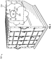
FIG. 4 shows a cargo container with the pressure vessel disposed therein; and -
FIG. 5 is a flow chart showing a method of configuring a pressure vessel for suppressing fire in a cargo container stowed in a cargo bay of an aircraft. - A detailed description of one or more embodiments of the disclosed apparatus and method are presented herein by way of exemplification and not limitation with reference to the Figures.
-
FIG. 1 illustrates an example of anaircraft 10. Theaircraft 10 includes twowings 22, ahorizontal stabilizer 32 andvertical stabilizer 30. The aircraft incudes aircraft engines on the twowings 22 or other locations surrounded by (or otherwise carried in)respective nacelles 20. In one embodiment theaircraft 10 is a commercial aircraft. Theaircraft 10 includes acargo bay 110 that, as illustrated, includes a plurality ofcargo containers 130. The plurality ofcargo containers 130 includes at least a first cargo container (cargo container) 120. Thecargo container 120 may be a unit load device (ULD). A ULD is a pallet or container used to load luggage, freight, and mail on wide-body aircraft configured according to regulations published by the International Air Transport Association (IATA). - A fire suppressant system (system) 200 is installed in the
cargo container 120 and configured to extinguish a fire within thecargo container 120. As will be disclosed in detail below, thesystem 200 enables quick suppression of a fire within thecargo container 120 before the fire breaches thecargo container 120, and without flooding the cargo bay 110. - Turning to
FIGS. 2 - 4 , thesystem 200 includes apressure vessel 210 within thecargo container 120. Thepressure vessel 210 may be connected to aceiling 214 of the cargo container 120 (FIG. 4 ), supported for example by arod 216 or other support structure. Thepressure vessel 210 is filled with a pressurized gaseous fire suppressant (fire suppressant) 220 (FIG. 2 ). The fire suppressant 220 may be Halon, Novec 1230, CF3I, 2-BTP, HFC-227ea, HFC-125, or HFC-236fa. Such fire suppressant 220 may be other materials capable of providing an inerting agent concentration inside thecargo container 120 upon agent release. - An
exterior surface 230 of thepressure vessel 210 defines a fire suppressant-opening 240 (FIG. 3 , illustrated schematically). Aseal member 250 is positioned against theexterior surface 230 of thepressure vessel 210 and covers the fire suppressant-opening 240. - A connection feature 260 (
FIGS. 2-3 , illustrated schematically) connects theseal member 250 to thepressure vessel 210. Theconnection feature 260 is configured to release the seal member when exposed to a predetermined minimum temperature, such as a temperature occurring during a fire. - According to an embodiments, the
connection feature 260 is an eutectic solder (solder). The solder has a relatively low melting temperature. For example, the solder has a melting temperature of 300 degrees Fahrenheit. Theconnection feature 260 therefore functions as a valve for thepressure vessel 210. - Upon melting of the solder, the
cover 250 is released allowing an inerting concentration of the fire suppressant 220 to be released from thepressure vessel 210 through the fire suppressant-opening 240 into thecargo container 120. Thus, the disclosed embodiments enable suppressing fires within thecargo container 120 stored in the 110 cargo bay of theaircraft 10. Of the plurality ofcargo containers 130, only thecargo container 120 is subjected to any impact of the container fire. - The fire suppressant-opening 240 on the
exterior surface 230 of thepressure vessel 210 may have a perimeter with a first shape S1 that is curved (FIG. 3 ). Theseal member 250 may have a second shape S2 that matches the first shape S1 of the fire suppressant-opening 240 (FIG. 3 ). For example, and as illustrated inFIG. 3 , both the fire suppressant-opening 240 and theseal member 250 may be circular. Theseal member 250 may be larger than the fire suppressant-opening 240 for sealing purposes. Theseal member 250 may be formed from a plate so that it is disk shaped. Other shapes of thepressure vessel 210, the fire suppressant-opening 240 and theseal member 250 are within the scope of the disclosure. - The
pressure vessel 210 may have a third shape S3 that is spherical (FIG. 3 ). In one embodiment a first diameter D1 of the fire suppressant-opening 240 is about at least twenty-five percent_of a second diameter D2 of thepressure vessel 210. This enables rapid expulsion offire suppressant 220 from within thepressure vessel 210. For example, the first diameter D1 of the fire suppressant-opening 240 is greater than three inches and the second diameter D2 of thepressure vessel 210 is substantially twelve inches. A ratio of a first volume V1 of thepressure vessel 210 to a second volume V2 of thecargo container 120 may be at least 1:1500 (FIG. 4 ). For example, the first volume V1 of thepressure vessel 210 may be at most 0.01 cubic feet and the second volume V2 of thecargo container 120 may be at least 150 cubic feet. This configuration enables storing enough of thefire suppressant 220 in thepressure vessel 210 to suppress a fire in thecargo container 120. The values mentioned in this paragraph are one embodiment. Depending upon the fire-fighting effectiveness of the agent being used, the values may differ from this one embodiment. - With the above disclosed embodiments, upon melting the solder forming the
connection feature 260, theseal member 250 will become loose. The pressure of thefire suppressant 220 will decouple theseal member 250 from thepressure vessel 210, at least partially. This will release thefire suppressant 220 from thepressure vessel 210. Thefire suppressant 220 will thus be discharged into thecargo container 120. - Turning to
FIG. 5 , a flow chart shows a method of configuring apressure vessel 210 for suppressing fire in acargo container 120 stowed in acargo bay 110 of anaircraft 10. As illustrated inblock 510 the method includes sealing aseal member 250 to apressure vessel 210 with aconnection feature 260 so that theseal member 250 covers a fire suppressant-opening 240 on anexternal surface 230 of thepressure vessel 210. As indicated a first diameter D1 of the fire suppressant-opening 240 is greater than twenty-five percent of a second diameter D2 of thepressure vessel 210, and a ratio of a first volume V1 of thepressure vessel 210 to a second volume V2 of thecargo container 120 is at least 1:1500. In addition, as indicated, theconnection feature 260 is configured to dissolve at a predetermined minimum temperature, for example 300 degrees Fahrenheit. As shown inblock 520 the method includes filling thepressure vessel 210 with compressed fire suppressant before sealing the seal member to thepressure vessel 210. - The terminology used herein is for the purpose of describing particular embodiments only and is not intended to be limiting of the present disclosure. As used herein, the singular forms "a", "an" and "the" are intended to include the plural forms as well, unless the context clearly indicates otherwise. It will be further understood that the terms "comprises" and/or "comprising," when used in this specification, specify the presence of stated features, integers, steps, operations, elements, and/or components, but do not preclude the presence or addition of one or more other features, integers, steps, operations, element components, and/or groups thereof.
- While the present disclosure has been described with reference to an exemplary embodiment or embodiments, it will be understood by those skilled in the art that various changes may be made and equivalents may be substituted for elements thereof without departing from the scope of the present disclosure. In addition, many modifications may be made to adapt a particular situation or material to the teachings of the present disclosure without departing from the essential scope thereof. Therefore, it is intended that the present disclosure not be limited to the particular embodiment disclosed as the best mode contemplated for carrying out this present disclosure, but that the present disclosure will include all embodiments falling within the scope of the claims.
Claims (15)
- A fire suppressant system for a cargo container, the system comprising:a pressure vessel disposed within the cargo container, a wall of the pressure vessel defining a fire suppressant-opening;a seal member that covers the fire suppressant-opening; anda connection feature connects the seal member to the pressure vessel, wherein the connection feature releases the seal member when exposed to a predetermined minimum temperature.
- The system of claim 1, wherein the connection feature is an eutectic solder.
- The system of claim 1 or 2, wherein the predetermined minimum temperature is 300 degrees Fahrenheit.
- The system of any preceding claim, wherein the pressure vessel is filled with a fire suppressant;
optionally wherein the fire suppressant is compressed and is one of Halon, Novec 1230, CF3I, 2-BTP, HFC-227ea, HFC-125, and HFC-236fa. - The system of any preceding claim, wherein the fire suppressant-opening on the exterior surface of the pressure vessel has a first shape that is curved.
- The system of claim 5, wherein the seal member has a perimeter with a second shape that matches the first shape of the fire suppressant-opening.
- The system of claim 5 or 6, wherein the fire suppressant-opening on the exterior surface is circular.
- The system of any preceding claim, wherein the exterior surface of the pressure vessel has a third shape that is spherical.
- The system of any preceding claim, wherein a first diameter of the fire suppressant-opening is greater than twenty-five percent of a second diameter of the pressure vessel;
optionally wherein the first diameter is greater than three inches and the second diameter is substantially twelve inches. - A cargo container comprising the system of any preceding claim; optionally wherein the cargo container is a unit load device (ULD).
- The cargo container of claim 10, wherein the cargo container includes a ceiling, and the pressure vessel is secured to the ceiling.
- The cargo container of claim 10 or 11, wherein a ratio of a first volume of the pressure vessel to a second volume of the cargo container is at least 1:1500; optionally, wherein the first volume is at most 0.1 cubic feet and the second volume is at least 150 cubic feet.
- An aircraft comprising:a cargo bay; andthe cargo container of claim 10, 11 or 12.
- The aircraft of claim 13, wherein the cargo container is a first cargo container of a plurality of cargo containers stowed in the cargo bay, and each of the plurality of cargo containers includes the fire suppressant system.
- A method of configuring a pressure vessel for suppressing fire in a cargo container stowed in a cargo bay of an aircraft, comprising:sealing a seal member to a pressure vessel with a connection feature so that the seal member covers a fire suppressant-opening on an external surface of the pressure vessel, wherein a first diameter of the fire suppressant-opening is greater than twenty-five percent of a second diameter of the pressure vessel and wherein the connection feature is configured to dissolve at a selected minimum temperature;optionally, further comprising filling the pressure vessel with compressed fire suppressant before sealing the seal member to the pressure vessel.
Applications Claiming Priority (1)
| Application Number | Priority Date | Filing Date | Title |
|---|---|---|---|
| US16/596,011 US11918838B2 (en) | 2019-10-08 | 2019-10-08 | Fire suppressant system for aircraft cargo container |
Publications (1)
| Publication Number | Publication Date |
|---|---|
| EP3804817A1 true EP3804817A1 (en) | 2021-04-14 |
Family
ID=68762507
Family Applications (1)
| Application Number | Title | Priority Date | Filing Date |
|---|---|---|---|
| EP19212737.1A Withdrawn EP3804817A1 (en) | 2019-10-08 | 2019-11-29 | Fire suppressant system for aircraft cargo container |
Country Status (2)
| Country | Link |
|---|---|
| US (1) | US11918838B2 (en) |
| EP (1) | EP3804817A1 (en) |
Citations (4)
| Publication number | Priority date | Publication date | Assignee | Title |
|---|---|---|---|---|
| EP0138195A2 (en) * | 1983-10-14 | 1985-04-24 | BAVARIA Feuerlösch-Apparatebau Albert Loos | Fire extinguisher |
| EP2937115A1 (en) * | 2014-04-24 | 2015-10-28 | Kidde Technologies, Inc. | Fire suppression system actuation apparatus and system |
| US20160263410A1 (en) * | 2010-12-30 | 2016-09-15 | William Armand Enk, SR. | Fire suppression system |
| WO2019160290A1 (en) * | 2018-02-13 | 2019-08-22 | 주식회사 뱅가드텍 | Automatic fire extinguisher |
Family Cites Families (11)
| Publication number | Priority date | Publication date | Assignee | Title |
|---|---|---|---|---|
| US3756321A (en) * | 1972-04-05 | 1973-09-04 | Star Sprinkler Corp | Flush type sprinkler |
| US3907037A (en) | 1974-08-05 | 1975-09-23 | Textron Inc | Disposable fire extinguisher |
| DE4224184C2 (en) * | 1992-07-22 | 1994-05-05 | Deugra Ges Fuer Brandschutzsys | Extinguishing agent container |
| US7456750B2 (en) | 2000-04-19 | 2008-11-25 | Federal Express Corporation | Fire suppression and indicator system and fire detection device |
| US6899184B2 (en) | 2001-07-30 | 2005-05-31 | The Boeing Company | Fire suppression system and method for an interior area of an aircraft lavatory waste container fire protection |
| CH697817B1 (en) * | 2002-06-12 | 2009-02-27 | Peter Kammer | reacting to heat closing a nozzle on a network for extinguishing agent. |
| US20080087446A1 (en) * | 2006-10-17 | 2008-04-17 | Ameron Global, Inc. | Self-activated fire extinguisher |
| US8752640B1 (en) | 2010-08-18 | 2014-06-17 | ULD Fire Systems, LLC | Method for detecting and suppressing fire in a container |
| US10343003B2 (en) * | 2014-10-02 | 2019-07-09 | The Boeing Company | Aircraft fire suppression system and method |
| US20170120089A1 (en) * | 2015-10-30 | 2017-05-04 | Firetrace Usa, Llc | Methods and apparatus for fire suppression system for transportable container |
| US10420969B2 (en) * | 2017-10-17 | 2019-09-24 | Kidde Technologies, Inc. | Commercial aviation fire extinguisher—strength increase method for in service and OEM fire protection |
-
2019
- 2019-10-08 US US16/596,011 patent/US11918838B2/en active Active
- 2019-11-29 EP EP19212737.1A patent/EP3804817A1/en not_active Withdrawn
Patent Citations (4)
| Publication number | Priority date | Publication date | Assignee | Title |
|---|---|---|---|---|
| EP0138195A2 (en) * | 1983-10-14 | 1985-04-24 | BAVARIA Feuerlösch-Apparatebau Albert Loos | Fire extinguisher |
| US20160263410A1 (en) * | 2010-12-30 | 2016-09-15 | William Armand Enk, SR. | Fire suppression system |
| EP2937115A1 (en) * | 2014-04-24 | 2015-10-28 | Kidde Technologies, Inc. | Fire suppression system actuation apparatus and system |
| WO2019160290A1 (en) * | 2018-02-13 | 2019-08-22 | 주식회사 뱅가드텍 | Automatic fire extinguisher |
Also Published As
| Publication number | Publication date |
|---|---|
| US11918838B2 (en) | 2024-03-05 |
| US20210101033A1 (en) | 2021-04-08 |
Similar Documents
| Publication | Publication Date | Title |
|---|---|---|
| US11752378B2 (en) | Fire suppressant device and method, including expansion agent | |
| US10625107B2 (en) | Device, system, and method for supplying fire suppressing agent to the interior of a container for an extended duration | |
| US9381388B2 (en) | Fire suppression system | |
| US20160263410A1 (en) | Fire suppression system | |
| US7614456B2 (en) | Fire retardant delivery system for fighting wild fires | |
| US8752640B1 (en) | Method for detecting and suppressing fire in a container | |
| EP2720760B1 (en) | Suppressing a fire condition in a cargo container | |
| US9227779B2 (en) | Cargo container for an aircraft | |
| US4763731A (en) | Fire suppression system for aircraft | |
| US9504862B2 (en) | Device for extinguishing fires | |
| US20130327548A1 (en) | Fire-protection storage means, a vehicle, and a method | |
| CN104602768B (en) | System and method for suppressing the condition of a fire in container | |
| US11918838B2 (en) | Fire suppressant system for aircraft cargo container | |
| GB2404431A (en) | Blast and fragmentation suppression device | |
| US10016641B2 (en) | Safety railcar | |
| JP2014512209A (en) | Fire extinguishing agent container and its practical provision method | |
| HK1233571A1 (en) | Method for supplying fire suppressing agent |
Legal Events
| Date | Code | Title | Description |
|---|---|---|---|
| PUAI | Public reference made under article 153(3) epc to a published international application that has entered the european phase |
Free format text: ORIGINAL CODE: 0009012 |
|
| STAA | Information on the status of an ep patent application or granted ep patent |
Free format text: STATUS: THE APPLICATION HAS BEEN PUBLISHED |
|
| AK | Designated contracting states |
Kind code of ref document: A1 Designated state(s): AL AT BE BG CH CY CZ DE DK EE ES FI FR GB GR HR HU IE IS IT LI LT LU LV MC MK MT NL NO PL PT RO RS SE SI SK SM TR |
|
| AX | Request for extension of the european patent |
Extension state: BA ME |
|
| STAA | Information on the status of an ep patent application or granted ep patent |
Free format text: STATUS: REQUEST FOR EXAMINATION WAS MADE |
|
| 17P | Request for examination filed |
Effective date: 20211014 |
|
| RBV | Designated contracting states (corrected) |
Designated state(s): AL AT BE BG CH CY CZ DE DK EE ES FI FR GB GR HR HU IE IS IT LI LT LU LV MC MK MT NL NO PL PT RO RS SE SI SK SM TR |
|
| STAA | Information on the status of an ep patent application or granted ep patent |
Free format text: STATUS: EXAMINATION IS IN PROGRESS |
|
| 17Q | First examination report despatched |
Effective date: 20221118 |
|
| STAA | Information on the status of an ep patent application or granted ep patent |
Free format text: STATUS: THE APPLICATION HAS BEEN WITHDRAWN |
|
| 18W | Application withdrawn |
Effective date: 20231221 |