EP3804637A1 - Handheld surgical instrument with heat management - Google Patents
Handheld surgical instrument with heat management Download PDFInfo
- Publication number
- EP3804637A1 EP3804637A1 EP20196528.2A EP20196528A EP3804637A1 EP 3804637 A1 EP3804637 A1 EP 3804637A1 EP 20196528 A EP20196528 A EP 20196528A EP 3804637 A1 EP3804637 A1 EP 3804637A1
- Authority
- EP
- European Patent Office
- Prior art keywords
- heat sink
- motor
- handpiece
- surgical instrument
- handheld surgical
- Prior art date
- Legal status (The legal status is an assumption and is not a legal conclusion. Google has not performed a legal analysis and makes no representation as to the accuracy of the status listed.)
- Granted
Links
Images




Classifications
-
- A—HUMAN NECESSITIES
- A61—MEDICAL OR VETERINARY SCIENCE; HYGIENE
- A61B—DIAGNOSIS; SURGERY; IDENTIFICATION
- A61B17/00—Surgical instruments, devices or methods
- A61B17/16—Instruments for performing osteoclasis; Drills or chisels for bones; Trepans
- A61B17/1613—Component parts
- A61B17/1622—Drill handpieces
-
- H—ELECTRICITY
- H02—GENERATION; CONVERSION OR DISTRIBUTION OF ELECTRIC POWER
- H02K—DYNAMO-ELECTRIC MACHINES
- H02K9/00—Arrangements for cooling or ventilating
- H02K9/22—Arrangements for cooling or ventilating by solid heat conducting material embedded in, or arranged in contact with, the stator or rotor, e.g. heat bridges
-
- A—HUMAN NECESSITIES
- A61—MEDICAL OR VETERINARY SCIENCE; HYGIENE
- A61B—DIAGNOSIS; SURGERY; IDENTIFICATION
- A61B17/00—Surgical instruments, devices or methods
- A61B17/16—Instruments for performing osteoclasis; Drills or chisels for bones; Trepans
- A61B17/1613—Component parts
- A61B17/1628—Motors; Power supplies
-
- A—HUMAN NECESSITIES
- A61—MEDICAL OR VETERINARY SCIENCE; HYGIENE
- A61B—DIAGNOSIS; SURGERY; IDENTIFICATION
- A61B17/00—Surgical instruments, devices or methods
- A61B17/24—Surgical instruments, devices or methods for use in the oral cavity, larynx, bronchial passages or nose; Tongue scrapers
-
- A—HUMAN NECESSITIES
- A61—MEDICAL OR VETERINARY SCIENCE; HYGIENE
- A61B—DIAGNOSIS; SURGERY; IDENTIFICATION
- A61B17/00—Surgical instruments, devices or methods
- A61B17/32—Surgical cutting instruments
-
- A—HUMAN NECESSITIES
- A61—MEDICAL OR VETERINARY SCIENCE; HYGIENE
- A61B—DIAGNOSIS; SURGERY; IDENTIFICATION
- A61B17/00—Surgical instruments, devices or methods
- A61B17/32—Surgical cutting instruments
- A61B17/320016—Endoscopic cutting instruments, e.g. arthroscopes, resectoscopes
- A61B17/32002—Endoscopic cutting instruments, e.g. arthroscopes, resectoscopes with continuously rotating, oscillating or reciprocating cutting instruments
-
- A—HUMAN NECESSITIES
- A61—MEDICAL OR VETERINARY SCIENCE; HYGIENE
- A61B—DIAGNOSIS; SURGERY; IDENTIFICATION
- A61B17/00—Surgical instruments, devices or methods
- A61B17/16—Instruments for performing osteoclasis; Drills or chisels for bones; Trepans
- A61B17/1662—Instruments for performing osteoclasis; Drills or chisels for bones; Trepans for particular parts of the body
- A61B17/1679—Instruments for performing osteoclasis; Drills or chisels for bones; Trepans for particular parts of the body for the ear
-
- A—HUMAN NECESSITIES
- A61—MEDICAL OR VETERINARY SCIENCE; HYGIENE
- A61B—DIAGNOSIS; SURGERY; IDENTIFICATION
- A61B17/00—Surgical instruments, devices or methods
- A61B17/16—Instruments for performing osteoclasis; Drills or chisels for bones; Trepans
- A61B17/1662—Instruments for performing osteoclasis; Drills or chisels for bones; Trepans for particular parts of the body
- A61B17/1688—Instruments for performing osteoclasis; Drills or chisels for bones; Trepans for particular parts of the body for the sinus or nose
-
- A—HUMAN NECESSITIES
- A61—MEDICAL OR VETERINARY SCIENCE; HYGIENE
- A61B—DIAGNOSIS; SURGERY; IDENTIFICATION
- A61B17/00—Surgical instruments, devices or methods
- A61B2017/00367—Details of actuation of instruments, e.g. relations between pushing buttons, or the like, and activation of the tool, working tip, or the like
- A61B2017/00398—Details of actuation of instruments, e.g. relations between pushing buttons, or the like, and activation of the tool, working tip, or the like using powered actuators, e.g. stepper motors, solenoids
-
- A—HUMAN NECESSITIES
- A61—MEDICAL OR VETERINARY SCIENCE; HYGIENE
- A61B—DIAGNOSIS; SURGERY; IDENTIFICATION
- A61B2217/00—General characteristics of surgical instruments
- A61B2217/002—Auxiliary appliance
- A61B2217/005—Auxiliary appliance with suction drainage system
Definitions
- This document pertains generally, but not by way of limitation, to surgical devices that can be used for various surgical procedures. More specifically, but not by way of limitation, the present application relates to a handheld surgical instrument.
- Occlusions within cavities of patients can cause a number of issues with a patient. These issues can include, for example, chronic rhinosinusitis, a deviated septum, nasal polyps, or the like.
- a physician can use a handheld surgical instrument having a microdebrider or a drill.
- Microdebriders can be used with a variety of implements depending on the procedure being performed.
- a microdebrider can include a cutting implement that can oscillate, i.e., moves in a back and forth rotational motion, and that can be used in Rhinologic procedures to remove softer tissues of the sinuses.
- a pre-bent implement having cutting implements can be used when surgery is being performed at difficult to reach surgical sites, such as the aforementioned sinus cavities.
- cutting implements that can facilitate 360-degree rotation can also be used with a single microdebrider.
- a single microdebrider can be used for a variety of procedures with a variety of implements.
- a drill can also be used.
- a drill can be used in Otologic procedures to remove bone in, and around, the ear.
- a microdebrider and/or a drill includes a motor, such as a DC motor, coupled with a driveshaft that rotates upon activation of the DC motor.
- the microdebrider and/or a drill can include a handpiece, where a user holds the microdebrider or the drill at the handpiece and manipulates the microdebrider or the drill using the handpiece during a procedure.
- the handpiece can be formed of a material having a relatively low thermal conductivity.
- the DC motor is usually positioned within the handpiece proximal to where the surgeon holds the microdebrider/drill.
- the DC motor can operate at high speed.
- the torque required by the DC motor to operate at high rpms draws great amounts of current.
- the increased current draw increases the heat dissipated by the DC motor during use.
- the handpiece is formed of a material having a relatively low thermal conductivity range, the handpiece can get very hot, thereby causing discomfort for a surgeon using the microdebrider/drill.
- a hotspot can form on the handpiece where the user holds the handpiece. In these situations, the user can be forced to stop using the microdebrider/drill until the handpiece cools sufficiently to allow holding.
- hot spotting may minimize the type of power that can be used with the microdebrider/drill.
- current designs preclude the use of motors with higher power outputs since these motors dissipate greater amounts of heat, which contribute to the problems discussed above.
- a handheld surgical device such as a microdebrider or a drill
- a handpiece that is capable of dissipating heat during use of the handheld surgical device.
- this handpiece should be able to dissipate heat for motors having increased power outputs.
- Examples of the present disclosure relate to a handpiece for a handheld surgical instrument that facilitates heat dissipation during use.
- examples of the present disclosure relate to a handheld surgical instrument that can include a handpiece, a motor having a motor housing, and a heat sink disposed around the motor housing.
- Examples of the present disclosure relate to a handpiece for a handheld surgical instrument that facilitates heat dissipation during use.
- a handheld surgical instrument can include a handpiece, a motor having a motor housing, and a heat sink disposed around the motor housing.
- the heat sink can include a plurality fins disposed along a length of the heat sink and that can radially extend from a surface of the heat sink. At least one fin of the plurality of fins can thermally couple with the handpiece.
- heat generated by the motor can be dissipated to the motor housing and then transferred to the heat sink. The heat can then be transferred to the handpiece via the fins.
- the handheld surgical instrument 100 can include a handpiece 102, a tube set 104, and a cutting assembly 106 that can include a cutting implement 108.
- the cutting implement 108 can be a burr or a blade.
- the handheld surgical instrument 100 can be a microdebrider that can be used to treat various rhinological conditions, such as chronic rhinosinusitis, a deviated septum, nasal polyps, or the like.
- the handheld surgical instrument 100 can be a drill that can be used in Otologic procedures to remove bone in, and around, the ear.
- the handpiece 102 can be formed of a material that can have a thermal conductivity in a range between about 1 W/m ⁇ K to about about 18 W/m ⁇ K, such as a polymer material.
- materials that can be used include Therma-TechTM Thermally Conducive Formulations available from PolyOneTM, headquartered in Avon Lake, Ohio.
- Therma-TechTM may include polyphenylene sulfide (PPS), polybutylene terephthalate (PBT), or Nylon 66.
- hot spotting can occur at a handpiece of the handheld surgical instrument.
- forming the handpiece 102 with a material that can have a thermal conductivity greater than about 1 W/m ⁇ K, to about 18 W/m ⁇ K and preferably in a range of about 10 W/m ⁇ K to about 18 W/m ⁇ K can allow dissipation of the heat generated by a motor of the handheld surgical instrument 100 during use.
- the material of the handpiece 102 can assist with reducing or minimizing hot spots in the handpiece 102.
- the handheld surgical instrument 100 can include a suction passage that allows for the passage of saline.
- a polymer material that can be used for the handpiece 102 can have a high electrical resistivity.
- using a polymer material for the handpiece 102 can act as an insulator to prevent electrical connection with potentially charged radio frequency saline that can pass through a suction passage of the handheld surgical instrument 100.
- the cutting implement 108 can be any type of blade that can be used for various procedures, such as functional endoscopic sinus surgery (FESS) procedures.
- the type of blades that can be used for the cutting implement 108 can include a standard blade with or without suction capability, bipolar and/or monopolar energy blades that can be used for hemostasis during a surgical procedure, or a rotatable blade.
- the cutting implement 108 can be a straight blade, an angled blade, or a turbinate blade.
- the handheld surgical instrument 100 can also include a burr in place of the cutting implement 108 for FESS procedures, such as a diamond bullet burr, a diamond ball burr, a diamond tapered burr, a fluted barrel burr, or an angled burr.
- the handheld surgical instrument 100 can be used for procedures other than FESS procedures. (the burr operation is the highest probability that can cause the temperature rise in the motor due to high speed and torque required to cut hard tissues such as bones. The blades 25k RPMs, have very minimal effect.).
- the handheld surgical instrument 100 can include a tonsil and adenoid blades and laryngeal blades.
- the handheld surgical instrument 100 can be used as a dental drill, as an ontology drill for ENT applications, or with a dremelTM.
- the handheld surgical instrument 100 can include a motor 110 disposed within the handpiece 102 that can provide power to the handheld surgical instrument 100 and can actuate the cutting implement 108, as shown with reference to Figures 2 and 3 .
- the motor 110 can be a DC motor capable of rotating at speeds up to about 35,000 rpms or higher.
- the motor 110 can be a DC motor capable of rotating at speeds up to about 100,000 rpms.
- the motor 110 can be cannulated to allow for the passage of components, such as a suction passage 112 from a suction connector 114, through the handpiece 102 and to a surgical site.
- components such as a suction passage 112 from a suction connector 114
- the suction passage 112 can allow for suction at a surgical site during use of the handheld surgical instrument 100.
- the suction passage 112 can allow for the passage of saline, such as RF saline, through the handheld surgical instrument 100 to a surgical site.
- the motor 110 can also have a motor housing 115 along with a motor shaft 116 disposed within the motor housing 115 where the motor shaft 116 can be communicatively coupled to the cutting implement 108.
- the motor shaft 116 can include a proximal end disposed within the motor housing and a distal end where the distal end of the motor shaft 116 can be communicatively coupled to the cutting implement 108.
- the distal end of the motor shaft 116 can include a rotatable debrider, a microdebrider, a rotatable cutting implement, or the like.
- the motor 110 can rotate the motor shaft 116 within and with respect to the motor housing 115 such that the cutting implement 108 can be actuated during a surgical procedure.
- An electrical communication pathway 118 can provide current to the motor 110 such that the motor 110 can rotate the motor shaft 116 and can actuate the cutting implement 108 during operation of the handheld surgical instrument 100.
- the motor 110 can be disposed within a heat sink 120 that can substantially enclose the motor 110.
- the heat sink 120 can extend between a first end 122 and a second end 124 where the motor 110 can be disposed within the heat sink 120 between the first and second ends 122 and 124.
- a coupling 126 can function to hold the motor 110 within the heat sink 120.
- the heat sink 120 can have an inner surface that is a substantially cylinder hollow.
- the coupling 126 can threadingly engage with the heat sink 120 at the second end 124.
- the coupling 126 can be secured to the heat sink 120 using any other technique that can allow for secure engagement between the heat sink 120 and the coupling 126, such as a frictional fit, an adhesive, welding, a dovetail connection, or the like.
- the suction connector 114 can threadingly engage with the coupling 126 such that suction can be provided via the suction passage 112 during use of the handheld surgical instrument 100.
- the suction connector 114 can be secured to the coupling 126 using any other technique that allows for secure engagement between the suction connector 114 and the coupling 126, such as a frictional fit, an adhesive, welding, a dovetail connection, or the like.
- the motor 110 can be cannulated. In examples where the motor 110 is cannulated, the suction connector 114 can provide suction via the suction passage 112 through the motor 110.
- the motor can include the motor shaft 116.
- the heat sink 120 can include an opening or passage through which the motor shaft 116 can pass, such as the heat sink opening 128 shown in Figure 4 .
- a seal 130 can sealingly engage with the motor shaft 116 at the heat sink opening 128 in order to seal the motor 110 within the heat sink 120.
- the seal 130 can be situated within a recess 132 of the heat sink 120 at the first end 122.
- the seal 130 can be any type of dynamic seal, such as a double-lip seal having a beveled edge.
- the seal 130 can include seal edges 134 and 136 that can sealingly engage with the motor shaft 116 such that as the motor shaft 116 rotates during operation, the seal edges 134 and 136 can remain in contact with the motor shaft 116.
- the seal 130 can be formed from VitonTM, any type of elastomer, fluoropolymer elastomer, or the like.
- the seal 130 can remain engaged with the motor shaft 116 via the seal edges 134 and 136 such that during reprocessing of the handheld surgical instrument 100, particulates, such as cleaning agents or any other type of fluids, do not enter the motor 110.
- other means can be used to seal the motor 110 with the heat sink 120, such as an o-ring or the like.
- the handheld surgical instrument 100 can include a seal 138 disposed in a recess 140 formed between the suction connector 114 and the coupling 126.
- the seal 138 can have characteristics that are similar to the seal 130.
- the seal 138 can be any type of dynamic seal, such as a double-lip seal having a beveled edge.
- the seal 138 can include seal edges that sealingly engage with the suction passage 112.
- the seal 138 can be formed from VitonTM, any type of elastomer, fluoropolymer elastomer, or the like.
- the seal 138 can remain engaged with the suction passage 112 via the seal edges such that during reprocessing of the handheld surgical instrument 100, particulates, such as cleaning agents or any other type of fluids, do not enter the motor 110.
- particulates such as cleaning agents or any other type of fluids
- other means can be used to seal the motor 110 with the heat sink 120, such as an o-ring or the like.
- the handheld surgical instrument 100 can include a coupling 142 disposed near or adjacent to the first end 122.
- the coupling 142 can threadingly engage with the heat sink 120 at the first end 122, as shown with reference to Figure 4 . While the coupling 142 is described as being secured to the heat sink 120 via threaded engagement, the coupling 142 can be secured to the heat sink 120 using any other technique that allows for secure engagement between the heat sink 120 and the coupling 142, such as a frictional fit, an adhesive, welding, a dovetail connection, or the like.
- the coupling 142 can include a coupling opening 144 through which the motor shaft 116 can pass when the motor 110 is disposed within the heat sink 120.
- the heat sink 120 can be configured to dissipate heat generated by the motor 110 during operation of the motor 110.
- the heat sink 120 can include fins 146 that extend outwardly from a bottom surface of the heat sink 120, such as in a radial direction, as more clearly shown with reference to Figures 6 and 7 .
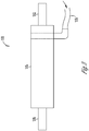
- the fins 146 can extend along a desired length of the heat sink 120, such as a length equivalent to a length of the motor 110 as shown with reference to Figure 6 .
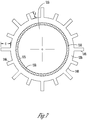
- the fins 146 can extend outwardly in a radial direction from a heat sink surface 148 of the heat sink 120, as shown in Figure 7 .
- the fins 146 can extend outwardly in a radial direction at different lengths X.
- each of the fins 146 can extend outwardly in a radial direction at a same length. In some examples, one or more of the fins 146 can physically contact the handpiece 102 as shown with reference to Figure 2 such that the fins 146 can be in thermal contact with the handpiece 102. In other examples, one or more of the fins 146 can be spaced apart from the handpiece 102 such that the fin does not physically contact the handpiece.
- the motor 110 can couple with the heat sink 120 using an adhesive putty 150.
- the adhesive putty 150 can be used during insertion of the motor 110 into the heat sink 120 where the adhesive putty 150 can thermally and physically couple the motor housing 115 with the heat sink 120.
- the adhesive putty 150 can ensure surface contact between the motor housing 115 and the heat sink 120.
- the adhesive putty 150 can adhere an outer surface of the motor housing 115 to an inner surface of the heat sink 120.
- using an adhesive putty 150 can obviate the need to use a keying mechanism or an anti-rotation feature.
- a keying mechanism would require the heat sink 120 to have a flat surface formed in a circular surface of the heat sink 120.
- an adhesive putty 150 can have a thermal conductivity in a range of about 2.0 W/m-K to about 6.0 W/m-K.
- examples of an adhesive putty 150 can include MasterbondTM Supreme 10ANHT available from MasterbondTM headquartered in Hackensack, New Jersey, and LiPolyTM Thermally Conductive S-Putty available from Shiu Li Technology LLC having a U.S. headquarters in San Jose, Ca.
- thermal adhesive can be used in place of the adhesive putty 150.
- An example of a thermal adhesive that can be used can include LoctiteTM Stik 'N SealTM available from Loctite Corporation having a global headquarters in Düsseldorf, Germany.
- other mechanisms can be used to couple the motor 110 with the heat sink 120.
- the heat sink 120 can be press fit around the motor housing 115 or the heat sink 120 can be welded to the motor housing 115. Further examples can include a shim or a coupling between the motor housing 115 and the heat sink 120.
- a ball and detent assembly can be used between the motor housing 115 and the heat sink 120.
- the heat sink 120 can be formed from any lightweight material having a high thermal conductivity, such as a thermal conductivity in a range between about 100W/m ⁇ K to about 250 W/m-K. Examples can include aluminum, gold, nickel, silver, zinc, and the like.
- the fins 146 can be formed from the same material used for the heat sink 120 or from a different material having a suitable thermal conductivity.
- the couplings 126 and 142 can be formed from any lightweight material having a high thermal conductivity, such as a thermal conductivity in a range between about 100W/m ⁇ K to about 250 W/m-K. Examples can include aluminum, gold, nickel, silver, zinc, and the like.
- the motor 110 can draw current from the electrical communication pathway, which increases an operating temperature of the motor 110.
- the motor 110 and the heat sink 120 being in thermal contact, such as via the adhesive putty 150, the heat generated from the motor 110 can be dissipated to the heat sink 120 from the motor 110 according to the second law of thermodynamics.
- the heat sink 120 is formed from a material having a high thermal conductivity as discussed above, the heat can quickly dissipate through the heat sink 120 and to the fins 146.
- the fins 146 can transfer heat either through convection (when one or more of the fins 146 is spaced apart from the handpiece 102), conduction (when one or more of the fins 146 contacts the handpiece 102) to the handpiece 102, thermal radiation, or a combination thereof.
- the handpiece 102 can be formed of a material having a low thermal conductivity in a range of about 1 W/m-K to about 18 W/m-K and can allow for even heat distribution and dissipation throughout the handpiece 102 in order to avoid hot spotting, as discussed above.
Landscapes
- Health & Medical Sciences (AREA)
- Surgery (AREA)
- Life Sciences & Earth Sciences (AREA)
- Engineering & Computer Science (AREA)
- Animal Behavior & Ethology (AREA)
- General Health & Medical Sciences (AREA)
- Biomedical Technology (AREA)
- Heart & Thoracic Surgery (AREA)
- Medical Informatics (AREA)
- Molecular Biology (AREA)
- Veterinary Medicine (AREA)
- Nuclear Medicine, Radiotherapy & Molecular Imaging (AREA)
- Public Health (AREA)
- Dentistry (AREA)
- Oral & Maxillofacial Surgery (AREA)
- Orthopedic Medicine & Surgery (AREA)
- Power Engineering (AREA)
- Otolaryngology (AREA)
- Pulmonology (AREA)
- Surgical Instruments (AREA)
Abstract
Description
- This application claims the benefit of priority to
U.S. Provisional Patent Application Serial No. 62/910,633, filed October 4, 2019 - This document pertains generally, but not by way of limitation, to surgical devices that can be used for various surgical procedures. More specifically, but not by way of limitation, the present application relates to a handheld surgical instrument.
- Occlusions within cavities of patients, such as sinus cavities, can cause a number of issues with a patient. These issues can include, for example, chronic rhinosinusitis, a deviated septum, nasal polyps, or the like. In order to remove these or other types of occlusions within cavities, a physician can use a handheld surgical instrument having a microdebrider or a drill. Microdebriders can be used with a variety of implements depending on the procedure being performed. A microdebrider can include a cutting implement that can oscillate, i.e., moves in a back and forth rotational motion, and that can be used in Rhinologic procedures to remove softer tissues of the sinuses. For example, a pre-bent implement having cutting implements can be used when surgery is being performed at difficult to reach surgical sites, such as the aforementioned sinus cavities. Moreover, cutting implements that can facilitate 360-degree rotation can also be used with a single microdebrider. Thus, a single microdebrider can be used for a variety of procedures with a variety of implements. As noted above, a drill can also be used. For example, a drill can be used in Otologic procedures to remove bone in, and around, the ear.
- Typically, a microdebrider and/or a drill includes a motor, such as a DC motor, coupled with a driveshaft that rotates upon activation of the DC motor. In addition, the microdebrider and/or a drill can include a handpiece, where a user holds the microdebrider or the drill at the handpiece and manipulates the microdebrider or the drill using the handpiece during a procedure. The handpiece can be formed of a material having a relatively low thermal conductivity. Moreover, the DC motor is usually positioned within the handpiece proximal to where the surgeon holds the microdebrider/drill.
- As the surgeon performs a procedure, the DC motor can operate at high speed. During a procedure, such as bone removal in an Otologic procedure, the torque required by the DC motor to operate at high rpms draws great amounts of current. As may be appreciated, the increased current draw increases the heat dissipated by the DC motor during use. Since the handpiece is formed of a material having a relatively low thermal conductivity range, the handpiece can get very hot, thereby causing discomfort for a surgeon using the microdebrider/drill. In particular, a hotspot can form on the handpiece where the user holds the handpiece. In these situations, the user can be forced to stop using the microdebrider/drill until the handpiece cools sufficiently to allow holding. Thus, hot spotting may minimize the type of power that can be used with the microdebrider/drill. In other words, current designs preclude the use of motors with higher power outputs since these motors dissipate greater amounts of heat, which contribute to the problems discussed above.
- Accordingly, what is needed is a handheld surgical device, such as a microdebrider or a drill, having a handpiece that is capable of dissipating heat during use of the handheld surgical device. Moreover, this handpiece should be able to dissipate heat for motors having increased power outputs.
- Examples of the present disclosure relate to a handpiece for a handheld surgical instrument that facilitates heat dissipation during use. In particular, examples of the present disclosure relate to a handheld surgical instrument that can include a handpiece, a motor having a motor housing, and a heat sink disposed around the motor housing.
-
-
Figure 1 illustrates a handheld surgical instrument in accordance with at least one example of the present disclosure. -
Figure 2 illustrates a handpiece of the handheld surgical instrument shown with reference toFigure 1 in accordance with at least one example of the present disclosure. -
Figure 3 shows a motor of the handheld surgical instrument in accordance with at least one example of the present disclosure. -
Figure 4 illustrates a motor disposed within a heat sink in accordance with at least one example of the present disclosure. -
Figure 5 shows a double-lip seal engaged with a motor shaft of the motor shown with reference toFigure 4 in accordance with at least one example of the present disclosure. -
Figures 6 and7 illustrate a heat sink and fins of the heat sink extending along the heat sink in accordance with at least one example of the present disclosure. - Examples of the present disclosure relate to a handpiece for a handheld surgical instrument that facilitates heat dissipation during use. In particular, examples of the present disclosure relate to a handheld surgical instrument that can include a handpiece, a motor having a motor housing, and a heat sink disposed around the motor housing. The heat sink can include a plurality fins disposed along a length of the heat sink and that can radially extend from a surface of the heat sink. At least one fin of the plurality of fins can thermally couple with the handpiece. Thus, during operation of the motor, heat generated by the motor can be dissipated to the motor housing and then transferred to the heat sink. The heat can then be transferred to the handpiece via the fins.
- Now making reference to the Figures, and more specifically
Figure 1 , a handheldsurgical instrument 100 is shown in accordance with at least one example of the present disclosure. The handheldsurgical instrument 100 can include ahandpiece 102, atube set 104, and acutting assembly 106 that can include acutting implement 108. Thecutting implement 108 can be a burr or a blade. In an example, the handheldsurgical instrument 100 can be a microdebrider that can be used to treat various rhinological conditions, such as chronic rhinosinusitis, a deviated septum, nasal polyps, or the like. In an example, the handheldsurgical instrument 100 can be a drill that can be used in Otologic procedures to remove bone in, and around, the ear. - During use of the handheld
surgical instrument 100, a surgeon can hold the handheldsurgical instrument 100 at thehandpiece 102 and can manipulate the handheldsurgical instrument 100 via thehandpiece 102. In various examples, thehandpiece 102 can be formed of a material that can have a thermal conductivity in a range between about 1 W/m·K to about about 18 W/m·K, such as a polymer material. Examples of materials that can be used include Therma-Tech™ Thermally Conducive Formulations available from PolyOne™, headquartered in Avon Lake, Ohio. In some examples, Therma-Tech™ may include polyphenylene sulfide (PPS), polybutylene terephthalate (PBT), or Nylon 66. As noted above, during use of prior art handheld surgical instruments, hot spotting can occur at a handpiece of the handheld surgical instrument. Here, forming thehandpiece 102 with a material that can have a thermal conductivity greater than about 1 W/m·K, to about 18 W/m·K and preferably in a range of about 10 W/m·K to about 18 W/m·K can allow dissipation of the heat generated by a motor of the handheldsurgical instrument 100 during use. As such, the material of thehandpiece 102 can assist with reducing or minimizing hot spots in thehandpiece 102. - Moreover, as will be detailed below, the handheld
surgical instrument 100 can include a suction passage that allows for the passage of saline. A polymer material that can be used for thehandpiece 102 can have a high electrical resistivity. Thus, using a polymer material for thehandpiece 102 can act as an insulator to prevent electrical connection with potentially charged radio frequency saline that can pass through a suction passage of the handheldsurgical instrument 100. - While the cutting
assembly 106 is shown engaged with a generic cutting implement 108, the cutting implement 108 can be any type of blade that can be used for various procedures, such as functional endoscopic sinus surgery (FESS) procedures. The type of blades that can be used for the cutting implement 108 can include a standard blade with or without suction capability, bipolar and/or monopolar energy blades that can be used for hemostasis during a surgical procedure, or a rotatable blade. Moreover, the cutting implement 108 can be a straight blade, an angled blade, or a turbinate blade. In addition, while the cutting implement 108 is shown, the handheldsurgical instrument 100 can also include a burr in place of the cutting implement 108 for FESS procedures, such as a diamond bullet burr, a diamond ball burr, a diamond tapered burr, a fluted barrel burr, or an angled burr. In addition, the handheldsurgical instrument 100 can be used for procedures other than FESS procedures. (the burr operation is the highest probability that can cause the temperature rise in the motor due to high speed and torque required to cut hard tissues such as bones. The blades 25k RPMs, have very minimal effect.). In these examples, the handheldsurgical instrument 100 can include a tonsil and adenoid blades and laryngeal blades. Moreover, in further examples, the handheldsurgical instrument 100 can be used as a dental drill, as an ontology drill for ENT applications, or with a dremel™. - Regardless of the type of cutting implement 108 used, the handheld
surgical instrument 100 can include amotor 110 disposed within thehandpiece 102 that can provide power to the handheldsurgical instrument 100 and can actuate the cutting implement 108, as shown with reference toFigures 2 and3 . In accordance with an example of the present disclosure, themotor 110 can be a DC motor capable of rotating at speeds up to about 35,000 rpms or higher. In further examples of the present disclosure where the handheldsurgical instrument 100 can function as a high speed drill, themotor 110 can be a DC motor capable of rotating at speeds up to about 100,000 rpms. In an example, themotor 110 can be cannulated to allow for the passage of components, such as asuction passage 112 from asuction connector 114, through thehandpiece 102 and to a surgical site. As those skilled in the art will appreciate, thesuction passage 112 can allow for suction at a surgical site during use of the handheldsurgical instrument 100. Moreover, thesuction passage 112 can allow for the passage of saline, such as RF saline, through the handheldsurgical instrument 100 to a surgical site. - The
motor 110 can also have amotor housing 115 along with amotor shaft 116 disposed within themotor housing 115 where themotor shaft 116 can be communicatively coupled to the cutting implement 108. In particular, themotor shaft 116 can include a proximal end disposed within the motor housing and a distal end where the distal end of themotor shaft 116 can be communicatively coupled to the cutting implement 108. In an example, the distal end of themotor shaft 116 can include a rotatable debrider, a microdebrider, a rotatable cutting implement, or the like. During operation, themotor 110 can rotate themotor shaft 116 within and with respect to themotor housing 115 such that the cutting implement 108 can be actuated during a surgical procedure. Anelectrical communication pathway 118 can provide current to themotor 110 such that themotor 110 can rotate themotor shaft 116 and can actuate the cutting implement 108 during operation of the handheldsurgical instrument 100. - In an example, the
motor 110 can be disposed within aheat sink 120 that can substantially enclose themotor 110. In particular, theheat sink 120 can extend between afirst end 122 and asecond end 124 where themotor 110 can be disposed within theheat sink 120 between the first and second ends 122 and 124. When themotor 110 is placed within theheat sink 120, in addition to thefirst end 122, acoupling 126 can function to hold themotor 110 within theheat sink 120. Theheat sink 120 can have an inner surface that is a substantially cylinder hollow. - In an example, the
coupling 126 can threadingly engage with theheat sink 120 at thesecond end 124. Alternatively or in addition, thecoupling 126 can be secured to theheat sink 120 using any other technique that can allow for secure engagement between theheat sink 120 and thecoupling 126, such as a frictional fit, an adhesive, welding, a dovetail connection, or the like. Thesuction connector 114 can threadingly engage with thecoupling 126 such that suction can be provided via thesuction passage 112 during use of the handheldsurgical instrument 100. Similar to thecoupling 126, while thesuction connector 114 is shown as being secured to thecoupling 126 via threaded engagement, thesuction connector 114 can be secured to thecoupling 126 using any other technique that allows for secure engagement between thesuction connector 114 and thecoupling 126, such as a frictional fit, an adhesive, welding, a dovetail connection, or the like. As previously mentioned, themotor 110 can be cannulated. In examples where themotor 110 is cannulated, thesuction connector 114 can provide suction via thesuction passage 112 through themotor 110. - As noted above, the motor can include the
motor shaft 116. In order to accommodate themotor shaft 116, theheat sink 120 can include an opening or passage through which themotor shaft 116 can pass, such as the heat sink opening 128 shown inFigure 4 . Moreover, aseal 130 can sealingly engage with themotor shaft 116 at the heat sink opening 128 in order to seal themotor 110 within theheat sink 120. Theseal 130 can be situated within arecess 132 of theheat sink 120 at thefirst end 122. Theseal 130 can be any type of dynamic seal, such as a double-lip seal having a beveled edge. For example, as shown with reference toFigure 5 , theseal 130 can include seal edges 134 and 136 that can sealingly engage with themotor shaft 116 such that as themotor shaft 116 rotates during operation, the seal edges 134 and 136 can remain in contact with themotor shaft 116. Theseal 130 can be formed from Viton™, any type of elastomer, fluoropolymer elastomer, or the like. In an example, theseal 130 can remain engaged with themotor shaft 116 via the seal edges 134 and 136 such that during reprocessing of the handheldsurgical instrument 100, particulates, such as cleaning agents or any other type of fluids, do not enter themotor 110. In addition to theseal 130, other means can be used to seal themotor 110 with theheat sink 120, such as an o-ring or the like. - Returning attention to
Figure 4 , the handheldsurgical instrument 100 can include aseal 138 disposed in arecess 140 formed between thesuction connector 114 and thecoupling 126. Theseal 138 can have characteristics that are similar to theseal 130. Thus, theseal 138 can be any type of dynamic seal, such as a double-lip seal having a beveled edge. Similar to theseal 130, theseal 138 can include seal edges that sealingly engage with thesuction passage 112. Theseal 138 can be formed from Viton™, any type of elastomer, fluoropolymer elastomer, or the like. Theseal 138 can remain engaged with thesuction passage 112 via the seal edges such that during reprocessing of the handheldsurgical instrument 100, particulates, such as cleaning agents or any other type of fluids, do not enter themotor 110. In addition to theseal 138, other means can be used to seal themotor 110 with theheat sink 120, such as an o-ring or the like. - The handheld
surgical instrument 100 can include acoupling 142 disposed near or adjacent to thefirst end 122. In an example, thecoupling 142 can threadingly engage with theheat sink 120 at thefirst end 122, as shown with reference toFigure 4 . While thecoupling 142 is described as being secured to theheat sink 120 via threaded engagement, thecoupling 142 can be secured to theheat sink 120 using any other technique that allows for secure engagement between theheat sink 120 and thecoupling 142, such as a frictional fit, an adhesive, welding, a dovetail connection, or the like. In order to allow themotor shaft 116 to engage with the cutting implement 108 or any other implement used with the handheldsurgical instrument 100, thecoupling 142 can include acoupling opening 144 through which themotor shaft 116 can pass when themotor 110 is disposed within theheat sink 120. - The
heat sink 120 can be configured to dissipate heat generated by themotor 110 during operation of themotor 110. Theheat sink 120 can includefins 146 that extend outwardly from a bottom surface of theheat sink 120, such as in a radial direction, as more clearly shown with reference toFigures 6 and7 . Thefins 146 can extend along a desired length of theheat sink 120, such as a length equivalent to a length of themotor 110 as shown with reference toFigure 6 . Moreover, thefins 146 can extend outwardly in a radial direction from aheat sink surface 148 of theheat sink 120, as shown inFigure 7 . In some examples, thefins 146 can extend outwardly in a radial direction at different lengths X. In other examples, each of thefins 146 can extend outwardly in a radial direction at a same length. In some examples, one or more of thefins 146 can physically contact thehandpiece 102 as shown with reference toFigure 2 such that thefins 146 can be in thermal contact with thehandpiece 102. In other examples, one or more of thefins 146 can be spaced apart from thehandpiece 102 such that the fin does not physically contact the handpiece. - In some examples, the
motor 110 can couple with theheat sink 120 using anadhesive putty 150. In particular, theadhesive putty 150 can be used during insertion of themotor 110 into theheat sink 120 where theadhesive putty 150 can thermally and physically couple themotor housing 115 with theheat sink 120. Theadhesive putty 150 can ensure surface contact between themotor housing 115 and theheat sink 120. Specifically, theadhesive putty 150 can adhere an outer surface of themotor housing 115 to an inner surface of theheat sink 120. Moreover, using anadhesive putty 150 can obviate the need to use a keying mechanism or an anti-rotation feature. To further illustrate, a keying mechanism would require theheat sink 120 to have a flat surface formed in a circular surface of theheat sink 120. Moreover, a keying mechanism would require that themotor housing 115 have a flat surface formed in a circular surface that is complementary to the flat surface formed in theheat sink 120. Thus, the flat surface of theheat sink 120 can abut the flat surface of themotor housing 115. By virtue of each of the flat surfaces abutting each other, themotor housing 115 can couple with theheat sink 120. In an example, anadhesive putty 150 can have a thermal conductivity in a range of about 2.0 W/m-K to about 6.0 W/m-K. Furthermore, examples of anadhesive putty 150 that can be used can include Masterbond™ Supreme 10ANHT available from Masterbond™ headquartered in Hackensack, New Jersey, and LiPoly™ Thermally Conductive S-Putty available from Shiu Li Technology LLC having a U.S. headquarters in San Jose, Ca. - In addition to using the
adhesive putty 150, other thermal materials can be used to couple themotor 110 with theheat sink 120. For example, a thermal adhesive can be used in place of theadhesive putty 150. An example of a thermal adhesive that can be used can include Loctite™ Stik 'N Seal™ available from Loctite Corporation having a global headquarters in Düsseldorf, Germany. Furthermore, other mechanisms can be used to couple themotor 110 with theheat sink 120. For example, theheat sink 120 can be press fit around themotor housing 115 or theheat sink 120 can be welded to themotor housing 115. Further examples can include a shim or a coupling between themotor housing 115 and theheat sink 120. In addition, a ball and detent assembly can be used between themotor housing 115 and theheat sink 120. - The
heat sink 120 can be formed from any lightweight material having a high thermal conductivity, such as a thermal conductivity in a range between about 100W/m·K to about 250 W/m-K. Examples can include aluminum, gold, nickel, silver, zinc, and the like. Thefins 146 can be formed from the same material used for theheat sink 120 or from a different material having a suitable thermal conductivity. Furthermore, thecouplings - During operation of the
motor 110, as noted above, themotor 110 can draw current from the electrical communication pathway, which increases an operating temperature of themotor 110. By virtue of themotor 110 and theheat sink 120 being in thermal contact, such as via theadhesive putty 150, the heat generated from themotor 110 can be dissipated to theheat sink 120 from themotor 110 according to the second law of thermodynamics. In an example where theheat sink 120 is formed from a material having a high thermal conductivity as discussed above, the heat can quickly dissipate through theheat sink 120 and to thefins 146. Thefins 146 can transfer heat either through convection (when one or more of thefins 146 is spaced apart from the handpiece 102), conduction (when one or more of thefins 146 contacts the handpiece 102) to thehandpiece 102, thermal radiation, or a combination thereof. As noted above, in some examples, thehandpiece 102 can be formed of a material having a low thermal conductivity in a range of about 1 W/m-K to about 18 W/m-K and can allow for even heat distribution and dissipation throughout thehandpiece 102 in order to avoid hot spotting, as discussed above. - The above detailed description includes references to the accompanying drawings, which form a part of the detailed description. The drawings show, by way of illustration, specific examples in which the invention can be practiced. These examples are also referred to herein as "examples." Such examples can include elements in addition to those shown or described. However, the present inventor also contemplates examples in which only those elements shown or described are provided. Moreover, the present inventor also contemplates examples using any combination or permutation of those elements shown or described (or one or more aspects thereof), either with respect to a particular example (or one or more aspects thereof), or with respect to other examples (or one or more aspects thereof) shown or described herein.
- In this document, the terms "a" or "an" are used, as is common in patent documents, to include one or more than one, independent of any other instances or usages of "at least one" or "one or more." In this document, the term "or" is used to refer to a nonexclusive or, such that "A or B" includes "A but not B," "B but not A," and "A and B," unless otherwise indicated. In this document, the terms "including" and "in which" are used as the plain-English equivalents of the respective terms "comprising" and "wherein." Also, in the following claims, the terms "including" and "comprising" are open-ended, that is, a system, device, article, composition, formulation, or process that includes elements in addition to those listed after such a term in a claim are still deemed to fall within the scope of that claim. Moreover, in the following claims, the terms "first," "second," and "third," etc. are used merely as labels, and are not intended to impose numerical requirements on their obj ects.
- Further examples of this disclosure are provided in the following paragraphs.
- Example 1. A handheld surgical instrument, comprising: a handpiece comprising a first material having a first thermal conductivity; a motor disposed within the handpiece and including a motor housing; and a heat sink disposed within the handpiece, the heat sink being thermally coupled to the motor housing, the heat sink comprising a second material having a second thermal conductivity that is greater in value than the first thermal conductivity.
- Example 2. The handheld surgical instrument of Example 1, further comprising a motor shaft, the motor shaft including: a proximal portion disposed within the motor; and a distal portion, wherein the distal portion of the motor shaft is coupled to a rotatable cutting implement.
- Example 3. The handheld surgical instrument of Example 1, wherein the heat sink is configured to enclose the motor.
- Example 4. The handheld surgical instrument of Example 1, further comprising a coupling configured to hold the motor within the heat sink.
- Example 5. The handheld surgical instrument of Example 1, wherein the first thermal conductivity is greater than or equal to approximately 1 W/m-K.
- Example 6. The handheld surgical instrument of Example 5, wherein the value of the second thermal conductivity is in a range between about 100W/m·K and about 250 W/m-K.
- Example 7. The handheld surgical instrument of Example 1, wherein the first thermal conductivity is in a range between about 1 W/m-K to about 18 W/m-K and the value of the second thermal conductivity is in a range between about 100W/m·K and about 250 W/m-K.
- Example 8. The handheld surgical instrument of Example 1, wherein the handpiece dissipates heat from the heat sink and the motor to reduce minimize one or more hot spots on the handpiece.
- Example 9. The handheld surgical instrument of Example 1, further comprising an adhesive disposed between the motor housing and the heat sink.
- Example 10. The handheld surgical instrument of Example 1, wherein the heat sink includes one or more fins radially extending from an outer surface of the heat sink.
- Example 11. The handheld surgical instrument of Example 10, wherein the one or more fins extends along a length of the heat sink that is substantially equal to a length of the motor.
- Example 12. The handheld surgical instrument of Example 10, wherein the one or more fins are thermally coupled with the handpiece.
- Example 13. The handheld surgical instrument of Example 10, wherein the one or more fins are spaced apart from the handpiece such that the heat sink and the one or more fins dissipate heat via convection to the handpiece.
- Example 14. The handheld surgical instrument of Example 10, wherein the one or more fins contact the handpiece such that the heat sink and the one or more fins dissipate heat via conduction to the handpiece.
- Example 15. A handpiece for a handheld surgical instrument, the handpiece comprising: a motor disposed within a motor housing, the motor and motor housing being partially disposed within the handpiece; and a heat sink disposed about the motor housing within the handpiece and being thermally coupled to the motor housing, the heat sink having a plurality of fins radially extending from a heat sink surface of the heat sink along a length of the heat sink where at least one of the fins is thermally coupled to the handpiece, wherein the handpiece has a first thermal conductivity and the heat sink has a second thermal conductivity that is greater in value than the first thermal conductivity.
- Example 16. The handpiece of Example 15, further comprising an adhesive disposed between the motor housing and the heat sink.
- Example 17. The handpiece of Example 15, wherein the first thermal conductivity is in a range between about 1 W/m-K and about 18 W/m-K.
- Example 18. The handpiece of Example 15, wherein the value of the second thermal conductivity is in a range between about 100W/m·K and about 250 W/m·K.
- Example 19. The handpiece of Example 15, wherein the handpiece dissipates heat from the heat sink and the motor to minimize one or more hot spots on the handpiece.
- Example 20. A handpiece for a handheld surgical instrument, the handpiece comprising: a motor disposed within a motor housing, the motor and motor housing being partially disposed within the handpiece; a heat sink disposed about the motor housing within the handpiece and being thermally coupled to the motor housing, the heat sink having a plurality of fins radially extending from a heat sink surface of the heat sink along a length of the heat sink where at least one of the fins is thermally coupled to the handpiece, wherein the handpiece has a first thermal conductivity and the heat sink has a second thermal conductivity that is greater in value than the first thermal conductivity; and an adhesive disposed between the motor housing and the heat sink, wherein the heat sink is configured to dissipate heat from the motor during operation of the motor.
- The above description is intended to be illustrative, and not restrictive. For example, the above-described examples (or one or more aspects thereof) can be used in combination with each other. Other examples can be used, such as by one of ordinary skill in the art upon reviewing the above description. The Abstract is provided to comply with 37 C.F.R. §1.72(b), to allow the reader to quickly ascertain the nature of the technical disclosure. It is submitted with the understanding that it will not be used to interpret or limit the scope or meaning of the claims. Also, in the above Detailed Description, various features can be grouped together to streamline the disclosure. This should not be interpreted as intending that an unclaimed disclosed feature is essential to any claim. Rather, inventive subject matter can lie in less than all features of a particular disclosed example. Thus, the following claims are hereby incorporated into the Detailed Description as examples or examples, with each claim standing on its own as a separate example, and it is contemplated that such examples can be combined with each other in various combinations or permutations. The scope of the invention should be determined with reference to the appended claims, along with the full scope of equivalents to which such claims are entitled.
Claims (15)
- A handheld surgical instrument, comprising:a handpiece comprising a first material having a first thermal conductivity;a motor at least partially disposed within the handpiece and including a motor housing; anda heat sink at least partially disposed within the handpiece, the heat sink being thermally coupled to the motor housing, the heat sink comprising a second material having a second thermal conductivity that is greater in value than the first thermal conductivity.
- The handheld surgical instrument of claim 1, further comprising a motor shaft, the motor shaft including:a proximal portion disposed within the motor; anda distal portion, wherein the distal portion of the motor shaft is coupled to a rotatable cutting implement.
- The handheld surgical instrument of claim 1 or 2, wherein the heat sink is configured to enclose the motor.
- The handheld surgical instrument of any of claims 1 to 3, further comprising a coupling configured to hold the motor within the heat sink.
- The handheld surgical instrument of any claims 1 to 4, wherein the first thermal conductivity is greater than or equal to approximately 1 W/m-K.
- The handheld surgical instrument of claim 5, wherein the first thermal conductivity is in a range between about 1 W/m·K to about 18 W/m-K.
- The handheld surgical instrument of any of claims 1 to 6, wherein the value of the second thermal conductivity is in a range between about 100W/m·K and about 250 W/m-K.
- The handheld surgical instrument of any of claims 1 to 7, wherein the handpiece dissipates heat from the heat sink and the motor to reduce minimize one or more hot spots on the handpiece.
- The handheld surgical instrument of any of claims 1 to 8, further comprising an adhesive disposed between the motor housing and the heat sink.
- The handheld surgical instrument of any of claims 1 to 9, wherein the heat sink includes one or more fins radially extending from an outer surface of the heat sink.
- The handheld surgical instrument of claim 10, wherein the one or more fins extends along a length of the heat sink that is substantially equal to a length of the motor.
- The handheld surgical instrument of claim 10 or 11, wherein the one or more fins are thermally coupled with the handpiece.
- The handheld surgical instrument of any of claims 10 to 12, wherein the one or more fins are spaced apart from the handpiece such that the heat sink and the one or more fins dissipate heat via convection to the handpiece.
- The handheld surgical instrument of any of claims 10 to 12, wherein the one or more fins contact the handpiece such that the heat sink and the one or more fins dissipate heat via conduction to the handpiece.
- A handpiece of a handheld surgical instrument according to any of claims 1 to 14, wherein the motor is disposed within the motor housing, the motor and motor housing being partially disposed within the handpiece; and
the heat sink is disposed about the motor housing within the handpiece and is thermally coupled to the motor housing, the heat sink having a plurality of fins radially extending from a heat sink surface of the heat sink along a length of the heat sink where at least one of the fins is thermally coupled to the handpiece.
Applications Claiming Priority (2)
| Application Number | Priority Date | Filing Date | Title |
|---|---|---|---|
| US201962910633P | 2019-10-04 | 2019-10-04 | |
| US17/004,111 US11777375B2 (en) | 2019-10-04 | 2020-08-27 | Handheld surgical instrument with heat management |
Publications (2)
| Publication Number | Publication Date |
|---|---|
| EP3804637A1 true EP3804637A1 (en) | 2021-04-14 |
| EP3804637B1 EP3804637B1 (en) | 2024-02-14 |
Family
ID=72560366
Family Applications (1)
| Application Number | Title | Priority Date | Filing Date |
|---|---|---|---|
| EP20196528.2A Active EP3804637B1 (en) | 2019-10-04 | 2020-09-16 | Handheld surgical instrument with heat management |
Country Status (3)
| Country | Link |
|---|---|
| US (1) | US11777375B2 (en) |
| EP (1) | EP3804637B1 (en) |
| JP (1) | JP2021058590A (en) |
Families Citing this family (1)
| Publication number | Priority date | Publication date | Assignee | Title |
|---|---|---|---|---|
| US12478359B2 (en) | 2022-09-13 | 2025-11-25 | Covidien Lp | Surgical instruments and manufacturing methods facilitating durable engagement between components of different materials |
Citations (5)
| Publication number | Priority date | Publication date | Assignee | Title |
|---|---|---|---|---|
| KR20100058206A (en) * | 2008-11-24 | 2010-06-03 | 안순애 | Handpiece including cooling means |
| WO2011085392A1 (en) * | 2010-01-11 | 2011-07-14 | Pro-Dex, Inc. | Handheld medical device with thermal padding |
| US20150201918A1 (en) * | 2014-01-02 | 2015-07-23 | Osseodyne Surgical Solutions, Llc | Surgical Handpiece |
| US20180078246A1 (en) * | 2015-04-08 | 2018-03-22 | Sciencemedic Co., Ltd. | Surgical handpiece having direction-shifting function |
| EP3524188A2 (en) * | 2018-02-13 | 2019-08-14 | Covidien LP | Powered tissue resecting device |
Family Cites Families (12)
| Publication number | Priority date | Publication date | Assignee | Title |
|---|---|---|---|---|
| US4759349A (en) | 1986-02-24 | 1988-07-26 | Vitalmetrics, Inc. | Surgical instrument having a heat sink for irrigation, aspiration, and illumination |
| US5543695A (en) | 1993-12-15 | 1996-08-06 | Stryker Corporation | Medical instrument with programmable torque control |
| US20020165549A1 (en) * | 2001-04-30 | 2002-11-07 | Medtronic, Inc. | Surgical instrument and attachment |
| US8388523B2 (en) | 2005-04-01 | 2013-03-05 | Welch Allyn, Inc. | Medical diagnostic instrument having portable illuminator |
| US8251916B2 (en) * | 2006-12-13 | 2012-08-28 | Devicor Medical Products, Inc. | Revolving tissue sample holder for biopsy device |
| DE502007005829D1 (en) | 2007-01-17 | 2011-01-13 | W & H Dentalwerk Buermoos Gmbh | Medical handle |
| US9072874B2 (en) | 2011-05-13 | 2015-07-07 | Boston Scientific Scimed, Inc. | Medical devices with a heat transfer region and a heat sink region and methods for manufacturing medical devices |
| DE102013001026A1 (en) | 2013-01-22 | 2014-07-24 | Karl Storz Gmbh & Co. Kg | Endoscopic and / or medical device and cooling device for an endoscope or a medical instrument |
| US9901364B2 (en) | 2014-02-20 | 2018-02-27 | Gyrus Acmi, Inc. | Heat pipe cooled burr including surgical instruments embodying same |
| US10178997B2 (en) * | 2014-09-24 | 2019-01-15 | Gyrus Acmi, Inc. | High-speed powered hand tool with improved motor cooling |
| JP2018082553A (en) * | 2016-11-16 | 2018-05-24 | 日本電産サンキョー株式会社 | motor |
| DE102018203314A1 (en) * | 2018-03-06 | 2019-09-12 | Geuder Ag | handle |
-
2020
- 2020-08-27 US US17/004,111 patent/US11777375B2/en active Active
- 2020-09-16 EP EP20196528.2A patent/EP3804637B1/en active Active
- 2020-10-02 JP JP2020167696A patent/JP2021058590A/en active Pending
Patent Citations (5)
| Publication number | Priority date | Publication date | Assignee | Title |
|---|---|---|---|---|
| KR20100058206A (en) * | 2008-11-24 | 2010-06-03 | 안순애 | Handpiece including cooling means |
| WO2011085392A1 (en) * | 2010-01-11 | 2011-07-14 | Pro-Dex, Inc. | Handheld medical device with thermal padding |
| US20150201918A1 (en) * | 2014-01-02 | 2015-07-23 | Osseodyne Surgical Solutions, Llc | Surgical Handpiece |
| US20180078246A1 (en) * | 2015-04-08 | 2018-03-22 | Sciencemedic Co., Ltd. | Surgical handpiece having direction-shifting function |
| EP3524188A2 (en) * | 2018-02-13 | 2019-08-14 | Covidien LP | Powered tissue resecting device |
Also Published As
| Publication number | Publication date |
|---|---|
| US20210104938A1 (en) | 2021-04-08 |
| EP3804637B1 (en) | 2024-02-14 |
| US11777375B2 (en) | 2023-10-03 |
| JP2021058590A (en) | 2021-04-15 |
Similar Documents
| Publication | Publication Date | Title |
|---|---|---|
| US11864824B2 (en) | Electrosurgical cutting instrument | |
| US12336731B2 (en) | High speed burr with flex shaft cooling and improved suction | |
| JP5696259B2 (en) | Blade holding mechanism for surgical instruments | |
| US10342572B2 (en) | Gear mechanism to drive oscillating shaft | |
| US20020165549A1 (en) | Surgical instrument and attachment | |
| US11777375B2 (en) | Handheld surgical instrument with heat management | |
| US20190365389A1 (en) | Integrated Suction and Cooling of Angled Burr | |
| US20200289151A1 (en) | Heat pipe cooled burr including surgical instruments embodying same | |
| US20180242986A1 (en) | Surgical Burs With Localized Auxiliary Flutes | |
| CA2551887A1 (en) | High speed surgical cutting instrument | |
| JP2008142551A (en) | Bipolar tissue debrider and its method | |
| CN103607965A (en) | Medical device with interference members to prevent reuse | |
| JP2015535483A (en) | Micro debrider with replaceable replaceable parts and method of attaching parts | |
| JP6695854B2 (en) | Device and method for cutting tissue | |
| JP2025113467A (en) | Surgical Cutting Bur | |
| US20240115286A1 (en) | Rf shaver auxiliary suction | |
| CN221450705U (en) | Milling handle and medical milling device | |
| US20230181237A1 (en) | Surgical device connection hub | |
| WO2002087422A2 (en) | Surgical instrument and attachment | |
| Zahedi et al. | Heat generation and thermal safety of powered instrumentation in endoscopic sinus surgery | |
| Mak et al. | Setup and Instruments | |
| Kazen | Modern electric handpieces feature improved benefits for today's dental surgeon | |
| CN117618078A (en) | Microdebrider with improved cutting and reduced obstruction | |
| CN108814683A (en) | A kind of soft tissue punching uses movement conversion mechanism |
Legal Events
| Date | Code | Title | Description |
|---|---|---|---|
| PUAI | Public reference made under article 153(3) epc to a published international application that has entered the european phase |
Free format text: ORIGINAL CODE: 0009012 |
|
| STAA | Information on the status of an ep patent application or granted ep patent |
Free format text: STATUS: REQUEST FOR EXAMINATION WAS MADE |
|
| STAA | Information on the status of an ep patent application or granted ep patent |
Free format text: STATUS: EXAMINATION IS IN PROGRESS |
|
| 17P | Request for examination filed |
Effective date: 20200916 |
|
| AK | Designated contracting states |
Kind code of ref document: A1 Designated state(s): AL AT BE BG CH CY CZ DE DK EE ES FI FR GB GR HR HU IE IS IT LI LT LU LV MC MK MT NL NO PL PT RO RS SE SI SK SM TR |
|
| AX | Request for extension of the european patent |
Extension state: BA ME |
|
| 17Q | First examination report despatched |
Effective date: 20210329 |
|
| RBV | Designated contracting states (corrected) |
Designated state(s): AL AT BE BG CH CY CZ DE DK EE ES FI FR GB GR HR HU IE IS IT LI LT LU LV MC MK MT NL NO PL PT RO RS SE SI SK SM TR |
|
| P01 | Opt-out of the competence of the unified patent court (upc) registered |
Effective date: 20230517 |
|
| GRAP | Despatch of communication of intention to grant a patent |
Free format text: ORIGINAL CODE: EPIDOSNIGR1 |
|
| STAA | Information on the status of an ep patent application or granted ep patent |
Free format text: STATUS: GRANT OF PATENT IS INTENDED |
|
| RIC1 | Information provided on ipc code assigned before grant |
Ipc: A61B 17/00 20060101ALN20230922BHEP Ipc: A61B 17/24 20060101ALI20230922BHEP Ipc: A61B 17/32 20060101ALI20230922BHEP Ipc: A61B 17/16 20060101AFI20230922BHEP |
|
| INTG | Intention to grant announced |
Effective date: 20231027 |
|
| RIC1 | Information provided on ipc code assigned before grant |
Ipc: A61B 17/00 20060101ALN20231017BHEP Ipc: A61B 17/24 20060101ALI20231017BHEP Ipc: A61B 17/32 20060101ALI20231017BHEP Ipc: A61B 17/16 20060101AFI20231017BHEP |
|
| GRAS | Grant fee paid |
Free format text: ORIGINAL CODE: EPIDOSNIGR3 |
|
| GRAA | (expected) grant |
Free format text: ORIGINAL CODE: 0009210 |
|
| STAA | Information on the status of an ep patent application or granted ep patent |
Free format text: STATUS: THE PATENT HAS BEEN GRANTED |
|
| AK | Designated contracting states |
Kind code of ref document: B1 Designated state(s): AL AT BE BG CH CY CZ DE DK EE ES FI FR GB GR HR HU IE IS IT LI LT LU LV MC MK MT NL NO PL PT RO RS SE SI SK SM TR |
|
| RAP3 | Party data changed (applicant data changed or rights of an application transferred) |
Owner name: GYRUS ACMI, INC. D/B/A OLYMPUS SURGICAL TECHNOLOGIES AMERICA |
|
| REG | Reference to a national code |
Ref country code: GB Ref legal event code: FG4D |
|
| REG | Reference to a national code |
Ref country code: CH Ref legal event code: EP |
|
| REG | Reference to a national code |
Ref country code: DE Ref legal event code: R096 Ref document number: 602020025564 Country of ref document: DE |
|
| REG | Reference to a national code |
Ref country code: IE Ref legal event code: FG4D |
|
| REG | Reference to a national code |
Ref country code: LT Ref legal event code: MG9D |
|
| REG | Reference to a national code |
Ref country code: NL Ref legal event code: MP Effective date: 20240214 |
|
| PG25 | Lapsed in a contracting state [announced via postgrant information from national office to epo] |
Ref country code: IS Free format text: LAPSE BECAUSE OF FAILURE TO SUBMIT A TRANSLATION OF THE DESCRIPTION OR TO PAY THE FEE WITHIN THE PRESCRIBED TIME-LIMIT Effective date: 20240614 |
|
| PG25 | Lapsed in a contracting state [announced via postgrant information from national office to epo] |
Ref country code: LT Free format text: LAPSE BECAUSE OF FAILURE TO SUBMIT A TRANSLATION OF THE DESCRIPTION OR TO PAY THE FEE WITHIN THE PRESCRIBED TIME-LIMIT Effective date: 20240214 |
|
| PG25 | Lapsed in a contracting state [announced via postgrant information from national office to epo] |
Ref country code: GR Free format text: LAPSE BECAUSE OF FAILURE TO SUBMIT A TRANSLATION OF THE DESCRIPTION OR TO PAY THE FEE WITHIN THE PRESCRIBED TIME-LIMIT Effective date: 20240515 |
|
| REG | Reference to a national code |
Ref country code: AT Ref legal event code: MK05 Ref document number: 1656363 Country of ref document: AT Kind code of ref document: T Effective date: 20240214 |
|
| PG25 | Lapsed in a contracting state [announced via postgrant information from national office to epo] |
Ref country code: NL Free format text: LAPSE BECAUSE OF FAILURE TO SUBMIT A TRANSLATION OF THE DESCRIPTION OR TO PAY THE FEE WITHIN THE PRESCRIBED TIME-LIMIT Effective date: 20240214 Ref country code: HR Free format text: LAPSE BECAUSE OF FAILURE TO SUBMIT A TRANSLATION OF THE DESCRIPTION OR TO PAY THE FEE WITHIN THE PRESCRIBED TIME-LIMIT Effective date: 20240214 Ref country code: RS Free format text: LAPSE BECAUSE OF FAILURE TO SUBMIT A TRANSLATION OF THE DESCRIPTION OR TO PAY THE FEE WITHIN THE PRESCRIBED TIME-LIMIT Effective date: 20240514 |
|
| PG25 | Lapsed in a contracting state [announced via postgrant information from national office to epo] |
Ref country code: ES Free format text: LAPSE BECAUSE OF FAILURE TO SUBMIT A TRANSLATION OF THE DESCRIPTION OR TO PAY THE FEE WITHIN THE PRESCRIBED TIME-LIMIT Effective date: 20240214 |
|
| PG25 | Lapsed in a contracting state [announced via postgrant information from national office to epo] |
Ref country code: AT Free format text: LAPSE BECAUSE OF FAILURE TO SUBMIT A TRANSLATION OF THE DESCRIPTION OR TO PAY THE FEE WITHIN THE PRESCRIBED TIME-LIMIT Effective date: 20240214 |
|
| PG25 | Lapsed in a contracting state [announced via postgrant information from national office to epo] |
Ref country code: RS Free format text: LAPSE BECAUSE OF FAILURE TO SUBMIT A TRANSLATION OF THE DESCRIPTION OR TO PAY THE FEE WITHIN THE PRESCRIBED TIME-LIMIT Effective date: 20240514 Ref country code: NO Free format text: LAPSE BECAUSE OF FAILURE TO SUBMIT A TRANSLATION OF THE DESCRIPTION OR TO PAY THE FEE WITHIN THE PRESCRIBED TIME-LIMIT Effective date: 20240514 Ref country code: NL Free format text: LAPSE BECAUSE OF FAILURE TO SUBMIT A TRANSLATION OF THE DESCRIPTION OR TO PAY THE FEE WITHIN THE PRESCRIBED TIME-LIMIT Effective date: 20240214 Ref country code: LT Free format text: LAPSE BECAUSE OF FAILURE TO SUBMIT A TRANSLATION OF THE DESCRIPTION OR TO PAY THE FEE WITHIN THE PRESCRIBED TIME-LIMIT Effective date: 20240214 Ref country code: IS Free format text: LAPSE BECAUSE OF FAILURE TO SUBMIT A TRANSLATION OF THE DESCRIPTION OR TO PAY THE FEE WITHIN THE PRESCRIBED TIME-LIMIT Effective date: 20240614 Ref country code: HR Free format text: LAPSE BECAUSE OF FAILURE TO SUBMIT A TRANSLATION OF THE DESCRIPTION OR TO PAY THE FEE WITHIN THE PRESCRIBED TIME-LIMIT Effective date: 20240214 Ref country code: GR Free format text: LAPSE BECAUSE OF FAILURE TO SUBMIT A TRANSLATION OF THE DESCRIPTION OR TO PAY THE FEE WITHIN THE PRESCRIBED TIME-LIMIT Effective date: 20240515 Ref country code: FI Free format text: LAPSE BECAUSE OF FAILURE TO SUBMIT A TRANSLATION OF THE DESCRIPTION OR TO PAY THE FEE WITHIN THE PRESCRIBED TIME-LIMIT Effective date: 20240214 Ref country code: ES Free format text: LAPSE BECAUSE OF FAILURE TO SUBMIT A TRANSLATION OF THE DESCRIPTION OR TO PAY THE FEE WITHIN THE PRESCRIBED TIME-LIMIT Effective date: 20240214 Ref country code: BG Free format text: LAPSE BECAUSE OF FAILURE TO SUBMIT A TRANSLATION OF THE DESCRIPTION OR TO PAY THE FEE WITHIN THE PRESCRIBED TIME-LIMIT Effective date: 20240214 Ref country code: AT Free format text: LAPSE BECAUSE OF FAILURE TO SUBMIT A TRANSLATION OF THE DESCRIPTION OR TO PAY THE FEE WITHIN THE PRESCRIBED TIME-LIMIT Effective date: 20240214 |
|
| PG25 | Lapsed in a contracting state [announced via postgrant information from national office to epo] |
Ref country code: PT Free format text: LAPSE BECAUSE OF FAILURE TO SUBMIT A TRANSLATION OF THE DESCRIPTION OR TO PAY THE FEE WITHIN THE PRESCRIBED TIME-LIMIT Effective date: 20240614 Ref country code: PL Free format text: LAPSE BECAUSE OF FAILURE TO SUBMIT A TRANSLATION OF THE DESCRIPTION OR TO PAY THE FEE WITHIN THE PRESCRIBED TIME-LIMIT Effective date: 20240214 |
|
| PG25 | Lapsed in a contracting state [announced via postgrant information from national office to epo] |
Ref country code: SE Free format text: LAPSE BECAUSE OF FAILURE TO SUBMIT A TRANSLATION OF THE DESCRIPTION OR TO PAY THE FEE WITHIN THE PRESCRIBED TIME-LIMIT Effective date: 20240214 Ref country code: PT Free format text: LAPSE BECAUSE OF FAILURE TO SUBMIT A TRANSLATION OF THE DESCRIPTION OR TO PAY THE FEE WITHIN THE PRESCRIBED TIME-LIMIT Effective date: 20240614 Ref country code: PL Free format text: LAPSE BECAUSE OF FAILURE TO SUBMIT A TRANSLATION OF THE DESCRIPTION OR TO PAY THE FEE WITHIN THE PRESCRIBED TIME-LIMIT Effective date: 20240214 Ref country code: LV Free format text: LAPSE BECAUSE OF FAILURE TO SUBMIT A TRANSLATION OF THE DESCRIPTION OR TO PAY THE FEE WITHIN THE PRESCRIBED TIME-LIMIT Effective date: 20240214 |
|
| PG25 | Lapsed in a contracting state [announced via postgrant information from national office to epo] |
Ref country code: DK Free format text: LAPSE BECAUSE OF FAILURE TO SUBMIT A TRANSLATION OF THE DESCRIPTION OR TO PAY THE FEE WITHIN THE PRESCRIBED TIME-LIMIT Effective date: 20240214 |
|
| PG25 | Lapsed in a contracting state [announced via postgrant information from national office to epo] |
Ref country code: SM Free format text: LAPSE BECAUSE OF FAILURE TO SUBMIT A TRANSLATION OF THE DESCRIPTION OR TO PAY THE FEE WITHIN THE PRESCRIBED TIME-LIMIT Effective date: 20240214 |
|
| PG25 | Lapsed in a contracting state [announced via postgrant information from national office to epo] |
Ref country code: CZ Free format text: LAPSE BECAUSE OF FAILURE TO SUBMIT A TRANSLATION OF THE DESCRIPTION OR TO PAY THE FEE WITHIN THE PRESCRIBED TIME-LIMIT Effective date: 20240214 Ref country code: EE Free format text: LAPSE BECAUSE OF FAILURE TO SUBMIT A TRANSLATION OF THE DESCRIPTION OR TO PAY THE FEE WITHIN THE PRESCRIBED TIME-LIMIT Effective date: 20240214 |
|
| PG25 | Lapsed in a contracting state [announced via postgrant information from national office to epo] |
Ref country code: SK Free format text: LAPSE BECAUSE OF FAILURE TO SUBMIT A TRANSLATION OF THE DESCRIPTION OR TO PAY THE FEE WITHIN THE PRESCRIBED TIME-LIMIT Effective date: 20240214 |
|
| PG25 | Lapsed in a contracting state [announced via postgrant information from national office to epo] |
Ref country code: SM Free format text: LAPSE BECAUSE OF FAILURE TO SUBMIT A TRANSLATION OF THE DESCRIPTION OR TO PAY THE FEE WITHIN THE PRESCRIBED TIME-LIMIT Effective date: 20240214 Ref country code: SK Free format text: LAPSE BECAUSE OF FAILURE TO SUBMIT A TRANSLATION OF THE DESCRIPTION OR TO PAY THE FEE WITHIN THE PRESCRIBED TIME-LIMIT Effective date: 20240214 Ref country code: RO Free format text: LAPSE BECAUSE OF FAILURE TO SUBMIT A TRANSLATION OF THE DESCRIPTION OR TO PAY THE FEE WITHIN THE PRESCRIBED TIME-LIMIT Effective date: 20240214 Ref country code: EE Free format text: LAPSE BECAUSE OF FAILURE TO SUBMIT A TRANSLATION OF THE DESCRIPTION OR TO PAY THE FEE WITHIN THE PRESCRIBED TIME-LIMIT Effective date: 20240214 Ref country code: DK Free format text: LAPSE BECAUSE OF FAILURE TO SUBMIT A TRANSLATION OF THE DESCRIPTION OR TO PAY THE FEE WITHIN THE PRESCRIBED TIME-LIMIT Effective date: 20240214 Ref country code: CZ Free format text: LAPSE BECAUSE OF FAILURE TO SUBMIT A TRANSLATION OF THE DESCRIPTION OR TO PAY THE FEE WITHIN THE PRESCRIBED TIME-LIMIT Effective date: 20240214 |
|
| REG | Reference to a national code |
Ref country code: DE Ref legal event code: R097 Ref document number: 602020025564 Country of ref document: DE |
|
| PG25 | Lapsed in a contracting state [announced via postgrant information from national office to epo] |
Ref country code: IT Free format text: LAPSE BECAUSE OF FAILURE TO SUBMIT A TRANSLATION OF THE DESCRIPTION OR TO PAY THE FEE WITHIN THE PRESCRIBED TIME-LIMIT Effective date: 20240214 |
|
| PLBE | No opposition filed within time limit |
Free format text: ORIGINAL CODE: 0009261 |
|
| STAA | Information on the status of an ep patent application or granted ep patent |
Free format text: STATUS: NO OPPOSITION FILED WITHIN TIME LIMIT |
|
| PG25 | Lapsed in a contracting state [announced via postgrant information from national office to epo] |
Ref country code: IT Free format text: LAPSE BECAUSE OF FAILURE TO SUBMIT A TRANSLATION OF THE DESCRIPTION OR TO PAY THE FEE WITHIN THE PRESCRIBED TIME-LIMIT Effective date: 20240214 |
|
| 26N | No opposition filed |
Effective date: 20241115 |
|
| PG25 | Lapsed in a contracting state [announced via postgrant information from national office to epo] |
Ref country code: MC Free format text: LAPSE BECAUSE OF FAILURE TO SUBMIT A TRANSLATION OF THE DESCRIPTION OR TO PAY THE FEE WITHIN THE PRESCRIBED TIME-LIMIT Effective date: 20240214 Ref country code: SI Free format text: LAPSE BECAUSE OF FAILURE TO SUBMIT A TRANSLATION OF THE DESCRIPTION OR TO PAY THE FEE WITHIN THE PRESCRIBED TIME-LIMIT Effective date: 20240214 |
|
| REG | Reference to a national code |
Ref country code: CH Ref legal event code: PL |
|
| PG25 | Lapsed in a contracting state [announced via postgrant information from national office to epo] |
Ref country code: LU Free format text: LAPSE BECAUSE OF NON-PAYMENT OF DUE FEES Effective date: 20240916 |
|
| GBPC | Gb: european patent ceased through non-payment of renewal fee |
Effective date: 20240916 |
|
| PG25 | Lapsed in a contracting state [announced via postgrant information from national office to epo] |
Ref country code: GB Free format text: LAPSE BECAUSE OF NON-PAYMENT OF DUE FEES Effective date: 20240916 |
|
| REG | Reference to a national code |
Ref country code: BE Ref legal event code: MM Effective date: 20240930 |
|
| PG25 | Lapsed in a contracting state [announced via postgrant information from national office to epo] |
Ref country code: BE Free format text: LAPSE BECAUSE OF NON-PAYMENT OF DUE FEES Effective date: 20240930 |
|
| PG25 | Lapsed in a contracting state [announced via postgrant information from national office to epo] |
Ref country code: FR Free format text: LAPSE BECAUSE OF NON-PAYMENT OF DUE FEES Effective date: 20240930 |
|
| PG25 | Lapsed in a contracting state [announced via postgrant information from national office to epo] |
Ref country code: CH Free format text: LAPSE BECAUSE OF NON-PAYMENT OF DUE FEES Effective date: 20240930 |
|
| PG25 | Lapsed in a contracting state [announced via postgrant information from national office to epo] |
Ref country code: IE Free format text: LAPSE BECAUSE OF NON-PAYMENT OF DUE FEES Effective date: 20240916 |
|
| PGFP | Annual fee paid to national office [announced via postgrant information from national office to epo] |
Ref country code: DE Payment date: 20250929 Year of fee payment: 6 |
|
| PG25 | Lapsed in a contracting state [announced via postgrant information from national office to epo] |
Ref country code: CY Free format text: LAPSE BECAUSE OF FAILURE TO SUBMIT A TRANSLATION OF THE DESCRIPTION OR TO PAY THE FEE WITHIN THE PRESCRIBED TIME-LIMIT; INVALID AB INITIO Effective date: 20200916 |
|
| PG25 | Lapsed in a contracting state [announced via postgrant information from national office to epo] |
Ref country code: HU Free format text: LAPSE BECAUSE OF FAILURE TO SUBMIT A TRANSLATION OF THE DESCRIPTION OR TO PAY THE FEE WITHIN THE PRESCRIBED TIME-LIMIT; INVALID AB INITIO Effective date: 20200916 |