EP3803291B1 - Sensor device for an aerodynamic element - Google Patents
Sensor device for an aerodynamic element Download PDFInfo
- Publication number
- EP3803291B1 EP3803291B1 EP19769049.8A EP19769049A EP3803291B1 EP 3803291 B1 EP3803291 B1 EP 3803291B1 EP 19769049 A EP19769049 A EP 19769049A EP 3803291 B1 EP3803291 B1 EP 3803291B1
- Authority
- EP
- European Patent Office
- Prior art keywords
- compliant
- sensor
- aerodynamic
- pitch angle
- sensor device
- Prior art date
- Legal status (The legal status is an assumption and is not a legal conclusion. Google has not performed a legal analysis and makes no representation as to the accuracy of the status listed.)
- Active
Links
Images



Classifications
-
- F—MECHANICAL ENGINEERING; LIGHTING; HEATING; WEAPONS; BLASTING
- F03—MACHINES OR ENGINES FOR LIQUIDS; WIND, SPRING, OR WEIGHT MOTORS; PRODUCING MECHANICAL POWER OR A REACTIVE PROPULSIVE THRUST, NOT OTHERWISE PROVIDED FOR
- F03D—WIND MOTORS
- F03D7/00—Controlling wind motors
- F03D7/02—Controlling wind motors the wind motors having rotation axis substantially parallel to the air flow entering the rotor
- F03D7/022—Adjusting aerodynamic properties of the blades
- F03D7/0224—Adjusting blade pitch
-
- G—PHYSICS
- G01—MEASURING; TESTING
- G01H—MEASUREMENT OF MECHANICAL VIBRATIONS OR ULTRASONIC, SONIC OR INFRASONIC WAVES
- G01H1/00—Measuring characteristics of vibrations in solids by using direct conduction to the detector
- G01H1/003—Measuring characteristics of vibrations in solids by using direct conduction to the detector of rotating machines
-
- F—MECHANICAL ENGINEERING; LIGHTING; HEATING; WEAPONS; BLASTING
- F03—MACHINES OR ENGINES FOR LIQUIDS; WIND, SPRING, OR WEIGHT MOTORS; PRODUCING MECHANICAL POWER OR A REACTIVE PROPULSIVE THRUST, NOT OTHERWISE PROVIDED FOR
- F03D—WIND MOTORS
- F03D17/00—Monitoring or testing of wind motors, e.g. diagnostics
-
- F—MECHANICAL ENGINEERING; LIGHTING; HEATING; WEAPONS; BLASTING
- F03—MACHINES OR ENGINES FOR LIQUIDS; WIND, SPRING, OR WEIGHT MOTORS; PRODUCING MECHANICAL POWER OR A REACTIVE PROPULSIVE THRUST, NOT OTHERWISE PROVIDED FOR
- F03D—WIND MOTORS
- F03D7/00—Controlling wind motors
- F03D7/02—Controlling wind motors the wind motors having rotation axis substantially parallel to the air flow entering the rotor
- F03D7/0296—Controlling wind motors the wind motors having rotation axis substantially parallel to the air flow entering the rotor to prevent, counteract or reduce noise emissions
-
- F—MECHANICAL ENGINEERING; LIGHTING; HEATING; WEAPONS; BLASTING
- F03—MACHINES OR ENGINES FOR LIQUIDS; WIND, SPRING, OR WEIGHT MOTORS; PRODUCING MECHANICAL POWER OR A REACTIVE PROPULSIVE THRUST, NOT OTHERWISE PROVIDED FOR
- F03D—WIND MOTORS
- F03D7/00—Controlling wind motors
- F03D7/02—Controlling wind motors the wind motors having rotation axis substantially parallel to the air flow entering the rotor
- F03D7/04—Automatic control; Regulation
- F03D7/042—Automatic control; Regulation by means of an electrical or electronic controller
-
- F—MECHANICAL ENGINEERING; LIGHTING; HEATING; WEAPONS; BLASTING
- F03—MACHINES OR ENGINES FOR LIQUIDS; WIND, SPRING, OR WEIGHT MOTORS; PRODUCING MECHANICAL POWER OR A REACTIVE PROPULSIVE THRUST, NOT OTHERWISE PROVIDED FOR
- F03D—WIND MOTORS
- F03D7/00—Controlling wind motors
- F03D7/02—Controlling wind motors the wind motors having rotation axis substantially parallel to the air flow entering the rotor
- F03D7/0256—Stall control
-
- F—MECHANICAL ENGINEERING; LIGHTING; HEATING; WEAPONS; BLASTING
- F05—INDEXING SCHEMES RELATING TO ENGINES OR PUMPS IN VARIOUS SUBCLASSES OF CLASSES F01-F04
- F05B—INDEXING SCHEME RELATING TO WIND, SPRING, WEIGHT, INERTIA OR LIKE MOTORS, TO MACHINES OR ENGINES FOR LIQUIDS COVERED BY SUBCLASSES F03B, F03D AND F03G
- F05B2270/00—Control
- F05B2270/30—Control parameters, e.g. input parameters
- F05B2270/328—Blade pitch angle
-
- F—MECHANICAL ENGINEERING; LIGHTING; HEATING; WEAPONS; BLASTING
- F05—INDEXING SCHEMES RELATING TO ENGINES OR PUMPS IN VARIOUS SUBCLASSES OF CLASSES F01-F04
- F05B—INDEXING SCHEME RELATING TO WIND, SPRING, WEIGHT, INERTIA OR LIKE MOTORS, TO MACHINES OR ENGINES FOR LIQUIDS COVERED BY SUBCLASSES F03B, F03D AND F03G
- F05B2270/00—Control
- F05B2270/30—Control parameters, e.g. input parameters
- F05B2270/333—Noise or sound levels
-
- F—MECHANICAL ENGINEERING; LIGHTING; HEATING; WEAPONS; BLASTING
- F05—INDEXING SCHEMES RELATING TO ENGINES OR PUMPS IN VARIOUS SUBCLASSES OF CLASSES F01-F04
- F05B—INDEXING SCHEME RELATING TO WIND, SPRING, WEIGHT, INERTIA OR LIKE MOTORS, TO MACHINES OR ENGINES FOR LIQUIDS COVERED BY SUBCLASSES F03B, F03D AND F03G
- F05B2270/00—Control
- F05B2270/30—Control parameters, e.g. input parameters
- F05B2270/334—Vibration measurements
-
- F—MECHANICAL ENGINEERING; LIGHTING; HEATING; WEAPONS; BLASTING
- F05—INDEXING SCHEMES RELATING TO ENGINES OR PUMPS IN VARIOUS SUBCLASSES OF CLASSES F01-F04
- F05B—INDEXING SCHEME RELATING TO WIND, SPRING, WEIGHT, INERTIA OR LIKE MOTORS, TO MACHINES OR ENGINES FOR LIQUIDS COVERED BY SUBCLASSES F03B, F03D AND F03G
- F05B2270/00—Control
- F05B2270/80—Devices generating input signals, e.g. transducers, sensors, cameras or strain gauges
-
- G—PHYSICS
- G01—MEASURING; TESTING
- G01H—MEASUREMENT OF MECHANICAL VIBRATIONS OR ULTRASONIC, SONIC OR INFRASONIC WAVES
- G01H9/00—Measuring mechanical vibrations or ultrasonic, sonic or infrasonic waves by using radiation-sensitive means, e.g. optical means
-
- Y—GENERAL TAGGING OF NEW TECHNOLOGICAL DEVELOPMENTS; GENERAL TAGGING OF CROSS-SECTIONAL TECHNOLOGIES SPANNING OVER SEVERAL SECTIONS OF THE IPC; TECHNICAL SUBJECTS COVERED BY FORMER USPC CROSS-REFERENCE ART COLLECTIONS [XRACs] AND DIGESTS
- Y02—TECHNOLOGIES OR APPLICATIONS FOR MITIGATION OR ADAPTATION AGAINST CLIMATE CHANGE
- Y02E—REDUCTION OF GREENHOUSE GAS [GHG] EMISSIONS, RELATED TO ENERGY GENERATION, TRANSMISSION OR DISTRIBUTION
- Y02E10/00—Energy generation through renewable energy sources
- Y02E10/70—Wind energy
- Y02E10/72—Wind turbines with rotation axis in wind direction
Definitions
- the following describes a sensor device for an aerodynamic element, especially for a wind turbine, an aerodynamic element, e.g. a wind turbine blade, with such sensor device, a method for controlling the angle of attack of an aerodynamic element, a controlling device and a wind turbine.
- Aerodynamic flow separation on an airfoil or wind turbine blade generally causes rapidly increasing drag, decrease in lift, and drastic increase in acoustic noise.
- Modern large turbines are therefore typically designed to avoid flow separation for the vast majority of operational conditions.
- flow separation can occur nonetheless, causing these detrimental effects to turbine performance.
- acoustic disadvantage is, the noise increases by approximately 10 dB(A) for separated flow.
- separation is often periodic with the blade passing frequency (e.g. for high shear conditions), which results in intense modulations in acoustic emission referred to as "thump noise”.
- Patent No. US 8,408,871 B2 uses a measure of dynamic pressure in the boundary layer of a rigid blade in a rake-like configuration to detect stall. The method is intrusive into the flow, potentially causing high frequency tonal noise under certain operating conditions. It also requires several pressure sensors and orients the sensors into the flow, which make this design susceptible to damage and clogging.
- a sensor device for detecting flow-separation on an aerodynamic element is provided according to claim 1.
- the sensor device comprises a number of compliant elements with aerodynamic and/or structural properties designed to allow flow-induced vibrational motion in an air current downstream of the trailing edge of an aerodynamic element and a sensor-element designed to measure vibrations of the number of compliant elements.
- the whole sensor device is designed such that it can be arranged downstream of the trailing edge of an aerodynamic element.
- the compliant elements are designed to vibrate in an air current, they must not be completely rigid, but must be able to deform in said wind current. However, a compliant element could deform in various manners.
- the vibrational amplitude of the compliant element should be catered to the sensitivity of the sensor.
- the measured vibrational signal should be significantly higher than the electrical noise floor of the sensor (including the noise of the data acquisition), but not so high as to ever overload the system.
- the whole compliant element could be highly compliant and deform in the air current, i.e. it deforms significantly as an unsteady, separation-induced flow passes.
- it could also be stiffer, i.e. elastic with a self-aligning torque, i.e. the deformation will be smaller, but the vibrational energy could be greater.
- the element could also comprise regions of varying stiffness, e.g. being thinner or more elastic or comprise hinges at a certain location and be more rigid or stiffer at another location, wherein the region with the lower stiffness should be positioned nearer to the aerodynamic element.
- the compliant elements could vibrate on behalf of strain deformations, or perhaps on behalf of some kind of hinged motion. There is preferably one row of compliant elements, but depending on the use, there also may be more stacked rows of compliant elements.
- An aerodynamic element comprises a sensor device as described above, wherein this sensor device is located downstream of the trailing edge of the aerodynamic element.
- the aerodynamic element is a wind turbine blade.
- the aerodynamic element may comprise only one sensor device at a certain region of the trailing edge, a sensor device arranged over a vast region of the trailing edge or several sensor devices arranged at several points or regions of the trailing edge.
- a method for controlling an angle of attack (AoA) of the aerodynamic element is provided according to claim 7.
- the angle of attack of the aerodynamic element or the relative speed between the aerodynamic element and the air current must be adjusted to avoid flow separation.
- the angle of attack is defined as the angle of a local section of the aerodynamic element with respect to the local inflow direction.
- flow separation depends on the angle of attack and the speed of the aerodynamic element relative to the air current.
- the pitch angle of the aerodynamic element and the rotation speed is what could be directly controlled by the wind turbine actuators. By adjusting the pitch angle, the angle of attack is adjusted relative to a steady air current. Since the angle of attack is also a function of the rotational speed, the rotational speed could be changed to alter the angle of attack.
- the aerodynamic element comprises a sensor device arranged over a vast region of the trailing edge or several sensor devices arranged at several points or regions of the trailing edge, as described above.
- the compliant element may have an arbitrary shape, as long as it is able to vibrate in an air current.
- the compliant element may have an arbitrary shape, as long as it is able to vibrate in an air current.
- there are preferred shapes that are able to perform a vibrational movement that is advantageous for embodiments of the present invention.
- a compliant element has an elongated shape, preferably with a ratio of length to width greater than 3 to 1, especially greater than 10 to 1, in particular greater than 30 to 1.
- the compliant element is designed to be attached perpendicular to the trailing edge of the aerodynamic element.
- this preferred compliant element is intended to be attached with its narrow side to an aerodynamic element and to protrude from the trailing edge of this aerodynamic element, preferably substantially following the curvature of the upper surface of the aerodynamic element, i.e. the surface directed to the suction side of the aerodynamic element in an incoming air current.
- a compliant element may have an arbitrary shape
- the Preferred dimensions of a compliant element are:
- a minimum width of 1 mm preferably a minimum width of 2 mm, and/or a maximum width of 40 mm, preferably a maximum width of 20 mm.
- the sensor device comprises more than two compliant elements that are protruding from a common root-element, wherein the compliant elements are arranged parallel to each other.
- the preferred spacing of the compliant elements are a minimum spacing to an adjacent compliant element of 1 mm, preferably of 2 mm, and/or a maximum spacing to an adjacent compliant element of 10 mm, preferably of 4 mm. If many compliant elements are used following this setup, this arrangement would result in a serration or a comb structure.
- compliant elements are expected to be no less than 3 cm long, typically 7-10 cm. Depending on the application, compliant elements are no longer than 20 cm. Preferred compliant elements in praxis are between 2 and 4 mm wide. Preferred compliant elements in praxis have a spacing to another of 1 to 2 mm. However, the generalized device made of compliant elements could also be significantly smaller, perhaps only 3 to 6 cm long or 1 to 3 cm long. These are very rough examples, since conceptually such a device could function with a very wide range of sizing.
- the number of compliant elements are designed as filaments of a comb-structure or as teeth of a serration, preferably as filaments of a combed serration or a combed trailing edge treatment device of a wind turbine blade. Since in some embodiments a serration is attached at the trailing edge of wind turbine blades to reduce acoustic emission, these serrations may be replaced by serrations or combs according to embodiments of this invention with elastic teeth or elastic filaments that are able to vibrate in the air current. Teeth of the serrations could e.g. be expected to be no less than 3 cm long, typically 7-10 cm, and no longer than 20 cm. The width is preferably proportional to the length, where aspect ratios between 1.2 and 2 are common. The teeth are preferably triangular.
- the filaments of the combs are rendered to accord to embodiments of the invention (to vibrate in an air current).
- the comb material is preferably the same as it is used for the serration, the dimensions of the filaments of the comb are chosen such that the filaments are able to vibrate in an air current.
- the ends of the filaments could be longer or shorter compared with the tips of the serration.
- the filaments lie preferably in the plane of the serration, but they could also be arranged above or below the serration, depending on the actual use.
- the sensor-element comprises a special sensor or a group of special sensors. These sensors do not necessarily have to measure the same parameter value, it is preferred that while using different sensors to use different types of sensors, as well. The advantage to measure different parameters is the reduction of systematic errors.
- a preferred sensor is an optical sensor for optical measurements, e.g. a camera.
- Another preferred sensor is a strain gauge-sensor connected with the compliant element.
- the strain gauge sensor could be integrated in a compliant member resulting in a compliant member formed as strain gauge element.
- Another preferred sensor is an accelerometer that is preferably mounted on the compliant element, measuring the acceleration of the compliant element.
- Another preferred sensor is an acoustic sensor, especially measuring sound waves generated by the aerodynamic element.
- Preferred combinations are combinations of a optical sensor together with one of the above listed alternatives, a strain gauge sensor combined with an acceleration sensor or an acoustic sensor. Preferred is also a combination of an acceleration sensor with an acoustic sensor.
- Optical detection with an optical sensor would have the potential benefit of detecting stall over a wide spanwise region, whereas a single strain gauge sensor is only usable only for a narrow region.
- acoustic measurements they are difficult to take because of the chaotic nature of the flow in the region the sensor device is usually positioned on an aerodynamic element. Detecting the acoustic signature of the compliant element would be difficult with all of the background noise.
- a compliant element as defined above, it has a certain resonance frequency (eigenfrequency), especially, if its self-aligning torque is great enough to result in a vibration if the compliant element is struck.
- an acoustic sensor or a device processing these measurements are designed such that they filter the resonance frequency from the sensor measurements and process the filtered resonance frequency, only. This could be enhanced by measuring the structure-borne sound near a compliant element or in a compliant element. This could e.g. be achieved by a microphone measuring only a narrow frequency band of the structure-borne sound at the trailing edge of a blade.
- the sensor device comprises a comparator-unit designed to determine if the vibration of the compliant element exceeds a predefined threshold.
- the comparator-unit is preferably designed to measure the amplitude or energy of the vibration (e.g. the variance of the compliant element's deflection taken by a camera), a lift coefficient or a strain gauge signal, an acceleration signal or an acoustic signal of the sensor-element.
- the comparator-unit may also calculate the gradient of a series of measurements and compare this gradient to a predefined threshold value (e.g. a maximum deviation from a mean-value).
- the device comprises a signal-unit designed to create a control signal based on the vibration of the compliant element.
- the control signal is designed to bias a control unit of a wind turbine to adjust the pitch angle and/or the rotation speed of the aerodynamic element according to the control signal.
- the control signal from the sensor device could preferably be a single value (e.g. a binary flag) that tells the main control system whether flow separation (or stall) is occurring on a critical portion of the blade, i.e. at the sensor location. It also could be an indicator for the strength of vibration (e.g. an integer value). How this is translated to a change in pitch could be handled in various ways, but likely would be handled by the main controller, e.g. of a wind turbine.
- a preferred method for controlling the angle of attack of an aerodynamic element according to embodiments of the invention comprise the following steps.
- the second pitch angle differs less than 5°, especially less than 2°, from the first pitch angle, i.e. the position where flow separation occurred.
- An alternative or additional preferred method for controlling the angle of attack of an aerodynamic element comprise the following steps.
- the threshold-value is determined with calibration measurements, preferably while measuring the vibrations with different pitch angles and/or different rotation speeds and/or during different wind velocities.
- a preferred method comprises the steps:
- Embodiments of the invention have the advantage that it provides a reliable and non-intrusive sensor device and method of detecting flow separation on a wind turbine blade, even for short periods of time.
- a sensor device implemented in a controlling device, appropriate compensation can be made, e.g. by adjusting the pitch angle and/or the rotation speed of the blade in order to reduce the operating angle of attack and re-attach the flow.
- Turbine operation with active stall detection would allow turbine designers to robustly operate turbines at higher angles of attack. This results directly in the possibility to reduce turbine loads and construct lighter rotors, what leads to more inexpensive turbines and improved cost of energy.
- Fig. 1 shows a cross section of a preferred aerodynamic element 1, e.g. a wind turbine blade, comprising a sensor device 2 according to embodiments of the invention.
- the sensor device 2 is located downstream of the trailing edge of the aerodynamic element 1.
- An air current C is indicated flowing against the aerodynamic element 1 in a certain angle of attack AoA.
- AoA a great angle of attack AoA is shown, where flow separation occurs at about the half of the upper surface of the aerodynamic element 1 forming a "separation zone" SZ where flow separation occurs. This is indicated with eddies at the trailing edge 1a of the aerodynamic element 1.
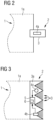
- Fig. 2 shows a top view on a preferred sensor device 2 positioned at the trailing edge 1a of an aerodynamic element 1.
- the sensor device 2 comprises a compliant element 3 having an elongated shape attached perpendicular to the trailing edge 1a of the aerodynamic element 1. This compliant element 3 is able to vibrate in an air current and will strongly vibrate if the air current is turbulent.
- An accelerometer 4a as sensor-element 4a is mounted on the compliant element 3, measuring the acceleration of the compliant element 3 during vibration.
- a strain gauge sensor 4b (see fig. 3 ) could be used that is included in the compliant element 3 so that the compliant element 3 itself can be used as a strain gauge element.
- Fig. 3 shows a top view on a further preferred sensor device 2.
- the sensor device 2 comprising a vast number of compliant elements 3 protruding from a common root-element 3a.
- the compliant elements 3 are designed as filaments of a comb-structure of a combed serration.
- the sensor device 2 comprises two different sensor-elements 4b, 4c, for example an optical sensor 4c for optical measurements (could also be an acoustic sensor) and a strain gauge sensor 4b.
- the sensor device 2 comprises a comparator-unit 5 designed to determine if the vibration of a compliant element 3, exceeds a predefined threshold, and a signal-unit 6 designed to create a control signal based on the vibration of a compliant element 3.
- the sensor-elements 4b and 4c are providing their measured values to the comparator-unit 5 for comparison with a predefined threshold value T.
- the signal-unit 6 of this sensor device 2 (shown in figure 3 ) preferably communicates with the control unit 8 of a wind turbine 7, biasing this control unit 8 to adjust the pitch angle P of the aerodynamic element 1.
- Fig. 4 shows two exemplary measurements of a sensor element at different angles of attack AoA.
- the upper diagram shows a measured lift coefficient C L of an aerodynamic element 1
- the lower diagram shows the amplitude A of the vibration of a compliant element 3 (see e.g. fig. 2 or 3 ).
- flow separation FS occurs (shown with the left dash/dottet line).
- stall S occurs (shown with the right dash/dottet line) i.e. as soon as lift starts to reduce with angle of attack.
- This can be seen by characteristic changes in the gradient of the upper diagram. For example, the Amplitude A will rise strongly at a steep gradient when flow separation FS occurs.
- a predefined threshold value T is shown. If the amplitude A exceeds this threshold value, this is interpreted that flow separation FS occurs. In this example, flow separation FS has already occurred but loss of lift (i.e. stall) has not when the threshold value T is exceeded. This could be optimized by calibration measurements or by a combined comparison of different values, e.g. the absolute amplitude A and the gradient of the amplitude A.
- Fig. 5 shows a block diagram of a preferred method for controlling the angle of attack AoA of an aerodynamic element 1.
- step I the vibration of a compliant element 3 of a sensor device 2 of the aerodynamic element 1 with the respective sensor-element 4a, 4b, 4c (see e.g. figures 2 or 3 ).
- the strength of the vibration of a compliant element 3 is measured continuously at different times, since the direction and/or strength of the wind current may change anytime.
- step II every measurement is compared with a predefined threshold-value T.
- step III it is decided, whether the threshold-value T is exceeded or not. Since the direction and/or strength of the wind current may change anytime, this decision should be repeated with every measurement. If the threshold-value T is not exceeded, the method continues with step I.
- step IV the pitch angle P of the aerodynamic element 1 (now called “first pitch angle P") is changed to a second pitch angle P, if the measurement exceeds the predefined threshold-value T.
- step I wherein the strength of the vibration of a compliant element at the second pitch angle P of the aerodynamic element 1 is measured.
- the change of the pitch angle is performed such that the second pitch angle P, where the threshold value T is not exceeded differs less than 5° from the first pitch angle P, where the threshold value T is exceeded.
- the threshold-value T could be predefined as static value. However, it could be determined with calibration measurements, preferably while measuring the vibrations with different pitch angles P and/or preferably during different wind velocities.
- Fig. 6 shows a preferred wind turbine 7 comprising three aerodynamic elements 1 (wind turbine blades) and a controlling device 9.
- the rotor of the wind turbine rotates in an air current in the direction of the straight arrow shown at the upper wind turbine blade.
- An aerodynamic element 1 comprises a sensor device 2 according to embodiments of the invention. Although due to enhance clearness, only one reference sign is shown, it is preferred that every aerodynamic element 1 comprises a sensor device 2.
- the sensor devices 2 each comprise a number of compliant elements 3 and sensor-elements 4a, 4b, 4c and could e.g. be designed as shown in figures 1 to 3 .
- the controlling device is formed by the sensor device(s) 2 and the control unit 8 of the turbine.
- the control unit 8 is able to adjust the pitch angle P (a change of the pitch angle P is shown by the curved arrow around the upper wind turbine blade).
- the pitch angle P of this aerodynamic element 1 is adjusted by the control unit 8.
Landscapes
- Engineering & Computer Science (AREA)
- Chemical & Material Sciences (AREA)
- Life Sciences & Earth Sciences (AREA)
- Sustainable Development (AREA)
- Sustainable Energy (AREA)
- Combustion & Propulsion (AREA)
- Mechanical Engineering (AREA)
- General Engineering & Computer Science (AREA)
- Physics & Mathematics (AREA)
- Fluid Mechanics (AREA)
- General Physics & Mathematics (AREA)
- Wind Motors (AREA)
- Measurement Of Mechanical Vibrations Or Ultrasonic Waves (AREA)
Description
- The following describes a sensor device for an aerodynamic element, especially for a wind turbine, an aerodynamic element, e.g. a wind turbine blade, with such sensor device, a method for controlling the angle of attack of an aerodynamic element, a controlling device and a wind turbine.
- Aerodynamic flow separation on an airfoil or wind turbine blade generally causes rapidly increasing drag, decrease in lift, and drastic increase in acoustic noise. Modern large turbines are therefore typically designed to avoid flow separation for the vast majority of operational conditions. However, under extreme and off-design conditions such as high wind-shear, yaw-error, and in strong gusts, flow separation can occur nonetheless, causing these detrimental effects to turbine performance.
- Aerodynamically, flow separation has the disadvantageous effect of reduced efficiency and power production, as well as unsteady loads and increased fatigue, thereby reducing the lifetime of a turbine.
- An acoustic disadvantage is, the noise increases by approximately 10 dB(A) for separated flow. However, separation is often periodic with the blade passing frequency (e.g. for high shear conditions), which results in intense modulations in acoustic emission referred to as "thump noise".
- The prior art reflects several methods for detecting aero-dynamic flow separation within the wind turbine industry. One method explained in Patent No.
US 8,408,871 B2 uses a measure of dynamic pressure in the boundary layer of a rigid blade in a rake-like configuration to detect stall. The method is intrusive into the flow, potentially causing high frequency tonal noise under certain operating conditions. It also requires several pressure sensors and orients the sensors into the flow, which make this design susceptible to damage and clogging. - Another sensor, described in Patent No.
EP 2075462 B1 , uses either a microphone or accelerometer to detect the stall condition. However, microphone measurements, while promising, were proven to be less unreliable in an internal study using data from a full-scale research turbine. It is unclear how robust a method based on accelerometer measurements might be, but it is known that such measurements are significantly influenced by inflow turbulence conditions. - Finally, another proposed method explained in Patent No.
US 8,002,524 B2 is based on a distribution of fiber-optic strain gauge measurements. Such a system would likely be quite expensive, due to both the cost of the fiber-optic sensor network and the added manufacturing cost of embedding the strain gauge within the blade. In addition,US2009308971 A1 discloses an airfoil system that improves the aerodynamic efficiency of a winged aircraft operating in the aircraft's cruise flight regime. - All solutions of the state of the art have their own disadvantages. It is very difficult to achieve an optimal easy suppression of flow separation.
- A sensor device for detecting flow-separation on an aerodynamic element is provided according to claim 1.
- The sensor device comprises a number of compliant elements with aerodynamic and/or structural properties designed to allow flow-induced vibrational motion in an air current downstream of the trailing edge of an aerodynamic element and a sensor-element designed to measure vibrations of the number of compliant elements. The whole sensor device is designed such that it can be arranged downstream of the trailing edge of an aerodynamic element.
- Since the compliant elements are designed to vibrate in an air current, they must not be completely rigid, but must be able to deform in said wind current. However, a compliant element could deform in various manners. The vibrational amplitude of the compliant element should be catered to the sensitivity of the sensor. Preferably, the measured vibrational signal should be significantly higher than the electrical noise floor of the sensor (including the noise of the data acquisition), but not so high as to ever overload the system. In the following there is described a number of examples that are preferred embodiments for compliant elements for embodiments of the invention.
- For example, the whole compliant element could be highly compliant and deform in the air current, i.e. it deforms significantly as an unsteady, separation-induced flow passes. In another example it could also be stiffer, i.e. elastic with a self-aligning torque, i.e. the deformation will be smaller, but the vibrational energy could be greater. The element could also comprise regions of varying stiffness, e.g. being thinner or more elastic or comprise hinges at a certain location and be more rigid or stiffer at another location, wherein the region with the lower stiffness should be positioned nearer to the aerodynamic element. The compliant elements could vibrate on behalf of strain deformations, or perhaps on behalf of some kind of hinged motion. There is preferably one row of compliant elements, but depending on the use, there also may be more stacked rows of compliant elements.
- An aerodynamic element according to embodiments of the invention comprises a sensor device as described above, wherein this sensor device is located downstream of the trailing edge of the aerodynamic element. Preferably, the aerodynamic element is a wind turbine blade. The aerodynamic element may comprise only one sensor device at a certain region of the trailing edge, a sensor device arranged over a vast region of the trailing edge or several sensor devices arranged at several points or regions of the trailing edge. A method for controlling an angle of attack (AoA) of the aerodynamic element is provided according to claim 7.
- It is clear that the angle of attack of the aerodynamic element or the relative speed between the aerodynamic element and the air current must be adjusted to avoid flow separation. The angle of attack is defined as the angle of a local section of the aerodynamic element with respect to the local inflow direction. Thus, flow separation depends on the angle of attack and the speed of the aerodynamic element relative to the air current. The pitch angle of the aerodynamic element and the rotation speed is what could be directly controlled by the wind turbine actuators. By adjusting the pitch angle, the angle of attack is adjusted relative to a steady air current. Since the angle of attack is also a function of the rotational speed, the rotational speed could be changed to alter the angle of attack.
- Since the angle of attack or the speed of an air current may vary along the span of the aerodynamic element, it is preferred that the aerodynamic element comprises a sensor device arranged over a vast region of the trailing edge or several sensor devices arranged at several points or regions of the trailing edge, as described above.
- In general, as already mentioned above, the compliant element may have an arbitrary shape, as long as it is able to vibrate in an air current. However, there are preferred shapes that are able to perform a vibrational movement that is advantageous for embodiments of the present invention.
- According to a preferred sensor device, a compliant element has an elongated shape, preferably with a ratio of length to width greater than 3 to 1, especially greater than 10 to 1, in particular greater than 30 to 1. The compliant element is designed to be attached perpendicular to the trailing edge of the aerodynamic element. Thus, this preferred compliant element is intended to be attached with its narrow side to an aerodynamic element and to protrude from the trailing edge of this aerodynamic element, preferably substantially following the curvature of the upper surface of the aerodynamic element, i.e. the surface directed to the suction side of the aerodynamic element in an incoming air current.
- Although a compliant element may have an arbitrary shape, the Preferred dimensions of a compliant element are:
- A minimum length of 1 cm, preferably a minimum length of 3 cm, and/or a maximum length of 20 cm, preferably a maximum length of 10 cm.
- A minimum width of 1 mm, preferably a minimum width of 2 mm, and/or a maximum width of 40 mm, preferably a maximum width of 20 mm.
- Preferably, the sensor device comprises more than two compliant elements that are protruding from a common root-element, wherein the compliant elements are arranged parallel to each other. The preferred spacing of the compliant elements are a minimum spacing to an adjacent compliant element of 1 mm, preferably of 2 mm, and/or a maximum spacing to an adjacent compliant element of 10 mm, preferably of 4 mm. If many compliant elements are used following this setup, this arrangement would result in a serration or a comb structure.
- Preferably in praxis, compliant elements are expected to be no less than 3 cm long, typically 7-10 cm. Depending on the application, compliant elements are no longer than 20 cm. Preferred compliant elements in praxis are between 2 and 4 mm wide. Preferred compliant elements in praxis have a spacing to another of 1 to 2 mm. However, the generalized device made of compliant elements could also be significantly smaller, perhaps only 3 to 6 cm long or 1 to 3 cm long. These are very rough examples, since conceptually such a device could function with a very wide range of sizing.
- According to the invention, the number of compliant elements are designed as filaments of a comb-structure or as teeth of a serration, preferably as filaments of a combed serration or a combed trailing edge treatment device of a wind turbine blade. Since in some embodiments a serration is attached at the trailing edge of wind turbine blades to reduce acoustic emission, these serrations may be replaced by serrations or combs according to embodiments of this invention with elastic teeth or elastic filaments that are able to vibrate in the air current. Teeth of the serrations could e.g. be expected to be no less than 3 cm long, typically 7-10 cm, and no longer than 20 cm. The width is preferably proportional to the length, where aspect ratios between 1.2 and 2 are common. The teeth are preferably triangular.
- In respect to the preferred combed serrations, at least the filaments of the combs are rendered to accord to embodiments of the invention (to vibrate in an air current). Since in a combed serration, the comb material is preferably the same as it is used for the serration, the dimensions of the filaments of the comb are chosen such that the filaments are able to vibrate in an air current. The ends of the filaments could be longer or shorter compared with the tips of the serration. The filaments lie preferably in the plane of the serration, but they could also be arranged above or below the serration, depending on the actual use.
- In a preferred sensor device, the sensor-element comprises a special sensor or a group of special sensors. These sensors do not necessarily have to measure the same parameter value, it is preferred that while using different sensors to use different types of sensors, as well. The advantage to measure different parameters is the reduction of systematic errors.
- A preferred sensor is an optical sensor for optical measurements, e.g. a camera. Another preferred sensor is a strain gauge-sensor connected with the compliant element. Alternatively (or in addition) the strain gauge sensor could be integrated in a compliant member resulting in a compliant member formed as strain gauge element. Another preferred sensor is an accelerometer that is preferably mounted on the compliant element, measuring the acceleration of the compliant element. Another preferred sensor is an acoustic sensor, especially measuring sound waves generated by the aerodynamic element. Preferred combinations are combinations of a optical sensor together with one of the above listed alternatives, a strain gauge sensor combined with an acceleration sensor or an acoustic sensor. Preferred is also a combination of an acceleration sensor with an acoustic sensor.
- Optical detection with an optical sensor (e.g. a camera), for example, would have the potential benefit of detecting stall over a wide spanwise region, whereas a single strain gauge sensor is only usable only for a narrow region.
- Regarding acoustic measurements, they are difficult to take because of the chaotic nature of the flow in the region the sensor device is usually positioned on an aerodynamic element. Detecting the acoustic signature of the compliant element would be difficult with all of the background noise. However, by using a compliant element as defined above, it has a certain resonance frequency (eigenfrequency), especially, if its self-aligning torque is great enough to result in a vibration if the compliant element is struck. Preferably an acoustic sensor or a device processing these measurements are designed such that they filter the resonance frequency from the sensor measurements and process the filtered resonance frequency, only. This could be enhanced by measuring the structure-borne sound near a compliant element or in a compliant element. This could e.g. be achieved by a microphone measuring only a narrow frequency band of the structure-borne sound at the trailing edge of a blade.
- According to the invention, the sensor device comprises a comparator-unit designed to determine if the vibration of the compliant element exceeds a predefined threshold. The comparator-unit is preferably designed to measure the amplitude or energy of the vibration (e.g. the variance of the compliant element's deflection taken by a camera), a lift coefficient or a strain gauge signal, an acceleration signal or an acoustic signal of the sensor-element. The comparator-unit may also calculate the gradient of a series of measurements and compare this gradient to a predefined threshold value (e.g. a maximum deviation from a mean-value).
- According to the invention, the device comprises a signal-unit designed to create a control signal based on the vibration of the compliant element. The control signal is designed to bias a control unit of a wind turbine to adjust the pitch angle and/or the rotation speed of the aerodynamic element according to the control signal. The control signal from the sensor device could preferably be a single value (e.g. a binary flag) that tells the main control system whether flow separation (or stall) is occurring on a critical portion of the blade, i.e. at the sensor location. It also could be an indicator for the strength of vibration (e.g. an integer value). How this is translated to a change in pitch could be handled in various ways, but likely would be handled by the main controller, e.g. of a wind turbine.
- A preferred method for controlling the angle of attack of an aerodynamic element according to embodiments of the invention comprise the following steps.
- a) Measuring the strength (e.g. the amplitude or the energy) of the vibration of a compliant element at different times at a first pitch angle of the aerodynamic element.
- b) Comparing this measurement with a predefined threshold-value.
- c) Changing the pitch angle of the aerodynamic element from the first pitch angle to a second pitch angle, if the measurement exceeds the predefined threshold-value.
- d) Measuring the strength of the vibration of a compliant element at the second pitch angle of the aerodynamic element.
- e) Repeating steps b) to d) until the measurement of the strength of the vibration at the second pitch angle lies below the predefined threshold-value. It should be noted, that the expressions "first pitch angle" and "second pitch angle" is only used to distinguish the different pitch angles before and after the change. The "first pitch angle" is the pitch angle before the change and the "second pitch angle" is the pitch angle after the change. During the repetition (in the case where the measurement at the second pitch angle still exceeds the predefined threshold-value), the "second pitch angle" will become the "first pitch angle".
- Since the best angle of attack is just before the drastic increase of vibration that occurs during flow separation, it is preferred that the second pitch angle differs less than 5°, especially less than 2°, from the first pitch angle, i.e. the position where flow separation occurred.
- An alternative or additional preferred method for controlling the angle of attack of an aerodynamic element according to embodiments of the invention, comprise the following steps.
- a) Measuring the strength (e.g. the amplitude or the energy) of the vibration of a compliant element at different times at a first rotation speed of the aerodynamic element.
- b) Comparing this measurement with a predefined threshold-value.
- c) Changing the rotation speed of the aerodynamic element from the first rotation speed to a second rotation speed (e.g. lower than the first rotation speed), if the measurement exceeds the predefined threshold-value.
- d) Measuring the strength of the vibration of a compliant element at the second rotation speed of the aerodynamic element.
- e) Repeating steps b) to d) until the measurement of the strength of the vibration at the second rotation speed lies below the predefined threshold-value. It should be noted, that the expressions "first rotation speed" and "second rotation speed" is only used to distinguish the different rotation speeds before and after the change (regarding "first rotation speed" and "second rotation speed" see the explanations in regard to "first pitch angle" and "second pitch angle").
- According to a preferred method the threshold-value is determined with calibration measurements, preferably while measuring the vibrations with different pitch angles and/or different rotation speeds and/or during different wind velocities.
- A preferred method comprises the steps:
- Measuring the vibration of a compliant element of a sensor device of the aerodynamic element at different pitch angles of the aerodynamic element.
- Adjusting the pitch angle of the aerodynamic element in the direction of the pitch angle where weaker vibrations have been measured in the case where the measurement exceeds a predefined threshold value.
- Embodiments of the invention have the advantage that it provides a reliable and non-intrusive sensor device and method of detecting flow separation on a wind turbine blade, even for short periods of time. With such a sensor device implemented in a controlling device, appropriate compensation can be made, e.g. by adjusting the pitch angle and/or the rotation speed of the blade in order to reduce the operating angle of attack and re-attach the flow.
- Turbine operation with active stall detection would allow turbine designers to robustly operate turbines at higher angles of attack. This results directly in the possibility to reduce turbine loads and construct lighter rotors, what leads to more inexpensive turbines and improved cost of energy.
- Some of the embodiments will be described in detail, with reference to the following figures, wherein like designations denote like members, wherein:
- Fig. 1
- shows a cross section of an embodiment of an aerodynamic element;
- Fig. 2
- shows a top view on an embodiment of a sensor device;
- Fig. 3
- shows a top view on a further embodiments of a sensor device;
- Fig. 4
- shows exemplary measurements of a sensor element;
- Fig. 5
- shows a block diagram of an embodiment of amethod; and
- Fig. 6
- shows an embodiment of awind turbine.
-
Fig. 1 shows a cross section of a preferred aerodynamic element 1, e.g. a wind turbine blade, comprising asensor device 2 according to embodiments of the invention. Thesensor device 2 is located downstream of the trailing edge of the aerodynamic element 1. - An air current C is indicated flowing against the aerodynamic element 1 in a certain angle of attack AoA. Here a great angle of attack AoA is shown, where flow separation occurs at about the half of the upper surface of the aerodynamic element 1 forming a "separation zone" SZ where flow separation occurs. This is indicated with eddies at the trailing
edge 1a of the aerodynamic element 1. -
Fig. 2 shows a top view on apreferred sensor device 2 positioned at the trailingedge 1a of an aerodynamic element 1. Thesensor device 2 comprises acompliant element 3 having an elongated shape attached perpendicular to the trailingedge 1a of the aerodynamic element 1. Thiscompliant element 3 is able to vibrate in an air current and will strongly vibrate if the air current is turbulent. - An
accelerometer 4a as sensor-element 4a is mounted on thecompliant element 3, measuring the acceleration of thecompliant element 3 during vibration. Here, also astrain gauge sensor 4b (seefig. 3 ) could be used that is included in thecompliant element 3 so that thecompliant element 3 itself can be used as a strain gauge element. -
Fig. 3 shows a top view on a furtherpreferred sensor device 2. Thesensor device 2 comprising a vast number ofcompliant elements 3 protruding from a common root-element 3a. Thecompliant elements 3 are designed as filaments of a comb-structure of a combed serration. - The
sensor device 2 comprises two different sensor-elements optical sensor 4c for optical measurements (could also be an acoustic sensor) and astrain gauge sensor 4b. - The
sensor device 2 comprises a comparator-unit 5 designed to determine if the vibration of acompliant element 3, exceeds a predefined threshold, and a signal-unit 6 designed to create a control signal based on the vibration of acompliant element 3. The sensor-elements unit 5 for comparison with a predefined threshold value T. - Looking at
figure 6 , the signal-unit 6 of this sensor device 2 (shown infigure 3 ) preferably communicates with thecontrol unit 8 of a wind turbine 7, biasing thiscontrol unit 8 to adjust the pitch angle P of the aerodynamic element 1. -
Fig. 4 shows two exemplary measurements of a sensor element at different angles of attack AoA. The upper diagram shows a measured lift coefficient CL of an aerodynamic element 1, the lower diagram shows the amplitude A of the vibration of a compliant element 3 (see e.g.fig. 2 or 3 ). At an angle of attack AoA greater 10° flow separation FS occurs (shown with the left dash/dottet line). At an angle of attack AoA of about 11.5°, stall S occurs (shown with the right dash/dottet line) i.e. as soon as lift starts to reduce with angle of attack. This can be seen by characteristic changes in the gradient of the upper diagram. For example, the Amplitude A will rise strongly at a steep gradient when flow separation FS occurs. - In the lower diagram, a predefined threshold value T is shown. If the amplitude A exceeds this threshold value, this is interpreted that flow separation FS occurs. In this example, flow separation FS has already occurred but loss of lift (i.e. stall) has not when the threshold value T is exceeded. This could be optimized by calibration measurements or by a combined comparison of different values, e.g. the absolute amplitude A and the gradient of the amplitude A.
-
Fig. 5 shows a block diagram of a preferred method for controlling the angle of attack AoA of an aerodynamic element 1. - In step I, the vibration of a
compliant element 3 of asensor device 2 of the aerodynamic element 1 with the respective sensor-element figures 2 or 3 ). The strength of the vibration of acompliant element 3 is measured continuously at different times, since the direction and/or strength of the wind current may change anytime. - In step II, every measurement is compared with a predefined threshold-value T.
- In step III it is decided, whether the threshold-value T is exceeded or not. Since the direction and/or strength of the wind current may change anytime, this decision should be repeated with every measurement. If the threshold-value T is not exceeded, the method continues with step I.
- In step IV, the pitch angle P of the aerodynamic element 1 (now called "first pitch angle P") is changed to a second pitch angle P, if the measurement exceeds the predefined threshold-value T.
- After that, the method continues with step I, wherein the strength of the vibration of a compliant element at the second pitch angle P of the aerodynamic element 1 is measured.
- It is preferred, that the change of the pitch angle is performed such that the second pitch angle P, where the threshold value T is not exceeded differs less than 5° from the first pitch angle P, where the threshold value T is exceeded.
- The threshold-value T could be predefined as static value. However, it could be determined with calibration measurements, preferably while measuring the vibrations with different pitch angles P and/or preferably during different wind velocities.
-
Fig. 6 shows a preferred wind turbine 7 comprising three aerodynamic elements 1 (wind turbine blades) and acontrolling device 9. The rotor of the wind turbine rotates in an air current in the direction of the straight arrow shown at the upper wind turbine blade. - An aerodynamic element 1 comprises a
sensor device 2 according to embodiments of the invention. Although due to enhance clearness, only one reference sign is shown, it is preferred that every aerodynamic element 1 comprises asensor device 2. Thesensor devices 2 each comprise a number ofcompliant elements 3 and sensor-elements figures 1 to 3 . - The controlling device is formed by the sensor device(s) 2 and the
control unit 8 of the turbine. Thecontrol unit 8 is able to adjust the pitch angle P (a change of the pitch angle P is shown by the curved arrow around the upper wind turbine blade). - In the case the sensor-
element sensor device 2 of an aerodynamic element 1, measures a strong increase of the vibration of the compliant element (3) of this sensor device, the pitch angle P of this aerodynamic element 1 is adjusted by thecontrol unit 8. - In the diagrams, like numbers refer to like objects throughout. Objects in the diagrams are not necessarily drawn to scale.
- It should be noted and understood that there can be improvements and modifications made of the present invention described in detail above without departing from the scope of the invention as set forth in the accompanying claims. For the sake of clarity, it is to be understood that the use of "a" or "an" throughout this application does not exclude a plurality, and "comprising" does not exclude other steps or elements. The mention of a "unit" or a "device" does not preclude the use of more than one unit or device.
- For the sake of clarity, it is to be understood that the use of "a" or "an" throughout this application does not exclude a plurality, and "comprising" does not exclude other steps or elements.
Claims (10)
- A sensor device (2) for detecting flow-separation on an aerodynamic element (1), comprising:a plurality of compliant elements (3) with aerodynamic and/or structural properties configured to allow flow-induced vibrational motion in an air current (C) downstream of a trailing edge (1a) of an aerodynamic element;a sensor-element (4a, 4b, 4c) configured to measure vibrations of the plurality of compliant elements (3);a comparator unit configured to determine if the vibration of a compliant element of the plurality of compliant elements (3), preferably the amplitude (A) or energy of the vibration, a lift coefficient (CL) or a strain gauge signal, an acceleration signal or an acoustic signal of the sensor-element, exceeds a predefined threshold; characterized in thatthe plurality of compliant elements are configured as filaments of a comb-structure or as teeth of a serration, or as a filament of a combed serration or a combed trailing edge treatment device of a wind turbine blade, and the sensor device further comprisesa signal-unit configured to create a control signal based on the vibration of a compliant element of the plurality of compliant elements (3), where in the case where the measurement exceeds a predefined threshold value the control signal is configured to bias a control unit of a wind turbine to adjust a pitch angle, P, and/or a rotation speed of the aerodynamic element according to the control signal.
- The sensor device according to claim 1, wherein the sensor-element (4a, 4b, 4c) comprises an acoustic sensor measuring sound waves in the aerodynamic element (1), wherein the acoustic sensor is designed such that it filters a resonance frequency of the compliant element from the sensor measurements and process the filtered resonance frequency, only.
- The sensor device according to claim 1 or 2, wherein a compliant element (3) of the plurality of compliant elements (3) has an elongated shape with a ratio of length to width greater than 3 to 1, and is designed to be attached perpendicular to the trailing edge (1a) of the aerodynamic element (1), preferably wherein a compliant element (3) hasa minimum length of 1 cm,
and/ora maximum length of 20 cm,
and/ora minimum width of 1 mm,
and/ora maximum width of 40 mm. - The sensor device according to claim 1, comprising more than two compliant elements (3) protruding from a common root-element (3a), wherein the compliant elements (3) are arranged parallel to each other having
a minimum spacing to an adjacent compliant element (3) of 1 mm, and/or a maximum spacing to an adjacent compliant element (3) of 10 mm. - The sensor device according to claim 1, wherein the sensor-element (4a, 4b, 4c) comprisea sensor (4c) for optical measurements,
ora strain gauge-sensor (4b) connected with a compliant element (3) or a compliant element (3) formed as strain gauge element,
oran accelerometer (4a) that is mounted on the compliant element (3), measuring an acceleration of the compliant element (3). - An aerodynamic element (1), comprising a sensor device (2) according to claim 1 located downstream of the trailing edge (1a) of the aerodynamic element (1).
- A method for controlling an angle of attack (AoA) of the aerodynamic element (1) according to claim 6, comprising the steps:- measuring a vibration of a compliant element (3) of a sensor device (2) of the aerodynamic element (1), and- adjusting a pitch angle (P) and/or a rotation speed of the aerodynamic element (1) based on a measurement of the vibration in the case where the measurement exceeds a predefined threshold value.
- The method according to claim 7, comprising the steps:a) measuring a strength of the vibration of a compliant element (3) at different times at a first pitch angle (P) of the aerodynamic element (1),b) comparing the measurement of step a) with a predefined threshold-value (T),c) changing the pitch angle (P) of the aerodynamic element (1) from the first pitch angle (P) to a second pitch angle (P), if the measurement exceeds the predefined threshold-value (T),d) measuring the strength of the vibration of a compliant element (1) at the second pitch angle (P) of the aerodynamic element (1),e) repeating the steps b) to d) until the measurement of the strength of the vibration at the second pitch angle (P) lies below the predefined threshold-value (T),
wherein the second pitch angle (P) differs less than 5° from the first pitch angle (P). - The method according to claim 8, wherein the threshold-value (T) is determined with calibration measurements, while measuring the vibrations with different pitch angles (P) and/or different rotation speeds and/or during different wind velocities.
- The method according to claim 9, comprising the steps:- measuring the vibration of a compliant element (3) of a sensor device (2) of the aerodynamic element (1) at different pitch angles (P) of the aerodynamic element (1), and- adjusting the pitch angle (P) of the aerodynamic element (1) in a direction of the pitch angle (P) where weaker vibrations have been measured in the case where the measurement exceeds a predefined threshold value (T).
Applications Claiming Priority (2)
| Application Number | Priority Date | Filing Date | Title |
|---|---|---|---|
| US16/132,795 US11408394B2 (en) | 2018-09-17 | 2018-09-17 | Sensor device for an aerodynamic element |
| PCT/EP2019/073121 WO2020057932A1 (en) | 2018-09-17 | 2019-08-29 | Sensor device for an aerodynamic element |
Publications (2)
| Publication Number | Publication Date |
|---|---|
| EP3803291A1 EP3803291A1 (en) | 2021-04-14 |
| EP3803291B1 true EP3803291B1 (en) | 2023-08-02 |
Family
ID=67956714
Family Applications (1)
| Application Number | Title | Priority Date | Filing Date |
|---|---|---|---|
| EP19769049.8A Active EP3803291B1 (en) | 2018-09-17 | 2019-08-29 | Sensor device for an aerodynamic element |
Country Status (5)
| Country | Link |
|---|---|
| US (1) | US11408394B2 (en) |
| EP (1) | EP3803291B1 (en) |
| CN (1) | CN112689746B (en) |
| DK (1) | DK3803291T3 (en) |
| WO (1) | WO2020057932A1 (en) |
Families Citing this family (2)
| Publication number | Priority date | Publication date | Assignee | Title |
|---|---|---|---|---|
| US11384732B2 (en) * | 2020-07-13 | 2022-07-12 | Siemens Gamesa Renewable Energy A/S | Noise reduction means for a wind turbine blade, wind turbine blade, wind turbine, and method for noise reduction for a wind turbine blade |
| US11462204B2 (en) * | 2020-09-08 | 2022-10-04 | Siemens Gamesa Renewable Energy A/S | Wind turbine and method for noise reduction for a wind turbine |
Citations (2)
| Publication number | Priority date | Publication date | Assignee | Title |
|---|---|---|---|---|
| US20090169378A1 (en) * | 2007-12-28 | 2009-07-02 | Detlef Menke | Wind turbine, wind turbine controller and method for controlling a wind turbine |
| US20160312763A1 (en) * | 2013-12-20 | 2016-10-27 | Lm Wp Patent Holding A/S | A Wind Turbine Blade Having Deployable Aerodynamic Devices |
Family Cites Families (21)
| Publication number | Priority date | Publication date | Assignee | Title |
|---|---|---|---|---|
| EP2044324A1 (en) * | 2006-07-07 | 2009-04-08 | Danmarks Tekniske Universitet | Variable trailing edge section geometry for wind turbine blade |
| US8882049B2 (en) | 2007-06-14 | 2014-11-11 | The United States Of America As Represented By The Administrator Of The National Aeronautics And Space Administration | Airfoil system for cruising flight |
| EP2120053A1 (en) * | 2008-05-14 | 2009-11-18 | ETH Zürich | System and method for monitoring flexible or mobile components with sensors |
| US8408871B2 (en) | 2008-06-13 | 2013-04-02 | General Electric Company | Method and apparatus for measuring air flow condition at a wind turbine blade |
| US8186950B2 (en) * | 2008-12-23 | 2012-05-29 | General Electric Company | Aerodynamic device for detection of wind turbine blade operation |
| DK200900420A (en) * | 2009-03-26 | 2010-09-27 | Vestas Wind Sys As | A wind turbine blade comprising a trailing edge flap and a piezoelectric actuator |
| US8002524B2 (en) | 2009-07-10 | 2011-08-23 | General Electric Company | Wind turbine aerodynamic separation control |
| GB2472437A (en) * | 2009-08-06 | 2011-02-09 | Vestas Wind Sys As | Wind turbine rotor blade control based on detecting turbulence |
| EP2333322A3 (en) * | 2009-11-30 | 2017-02-22 | Vestas Wind Systems A/S | Measuring loads on wind turbine blades |
| US8123478B2 (en) * | 2010-05-26 | 2012-02-28 | General Electric Company | Systems and methods for monitoring a condition of a rotor blade for a wind turbine |
| CN103608653B (en) * | 2011-04-13 | 2015-10-21 | 维斯塔斯风力系统集团公司 | Comprise the wind turbine of optical sensor system |
| EP2679808A1 (en) * | 2012-06-28 | 2014-01-01 | Siemens Aktiengesellschaft | Stall detection of wind turbine blades |
| US20140072441A1 (en) * | 2012-09-12 | 2014-03-13 | Michael J. Asheim | Load and noise mitigation system for wind turbine blades |
| DE102012111838B4 (en) * | 2012-12-05 | 2014-12-04 | Industrieanlagen-Betriebsgesellschaft Mbh | Test bench for a rotor blade, arrangement with such a test bench and method for operating such a test bench |
| CN103334872B (en) * | 2013-06-08 | 2015-07-15 | 中国大唐集团科学技术研究院有限公司 | Wind turbine blade and wind turbine |
| US9651443B2 (en) | 2014-06-06 | 2017-05-16 | General Electric Company | System and method for protecting rotary machines |
| WO2016066170A1 (en) | 2014-10-29 | 2016-05-06 | Vestas Wind Systems A/S | Turbulence sensor for wind turbines |
| EP3088733B1 (en) * | 2015-04-27 | 2018-10-17 | Envision Energy (Jiangsu) Co., Ltd. | Method for operating a wind turbine based on degradation of wind turbine blade |
| DK3096003T3 (en) * | 2015-05-21 | 2021-05-10 | Siemens Gamesa Renewable Energy As | Rotor wing with notches for a wind turbine |
| US11002246B2 (en) | 2016-04-15 | 2021-05-11 | Siemens Gamesa Renewable Energy A/S | Rotor blade with a serrated trailing edge |
| ES2992787T3 (en) * | 2016-05-27 | 2024-12-18 | Siemens Gamesa Renewable Energy As | Rotor blade with noise reduction means |
-
2018
- 2018-09-17 US US16/132,795 patent/US11408394B2/en active Active
-
2019
- 2019-08-29 WO PCT/EP2019/073121 patent/WO2020057932A1/en not_active Ceased
- 2019-08-29 DK DK19769049.8T patent/DK3803291T3/en active
- 2019-08-29 EP EP19769049.8A patent/EP3803291B1/en active Active
- 2019-08-29 CN CN201980060949.1A patent/CN112689746B/en active Active
Patent Citations (2)
| Publication number | Priority date | Publication date | Assignee | Title |
|---|---|---|---|---|
| US20090169378A1 (en) * | 2007-12-28 | 2009-07-02 | Detlef Menke | Wind turbine, wind turbine controller and method for controlling a wind turbine |
| US20160312763A1 (en) * | 2013-12-20 | 2016-10-27 | Lm Wp Patent Holding A/S | A Wind Turbine Blade Having Deployable Aerodynamic Devices |
Also Published As
| Publication number | Publication date |
|---|---|
| DK3803291T3 (en) | 2023-09-11 |
| CN112689746A (en) | 2021-04-20 |
| US20200088162A1 (en) | 2020-03-19 |
| WO2020057932A1 (en) | 2020-03-26 |
| US11408394B2 (en) | 2022-08-09 |
| EP3803291A1 (en) | 2021-04-14 |
| CN112689746B (en) | 2024-02-02 |
Similar Documents
| Publication | Publication Date | Title |
|---|---|---|
| EP2547893B1 (en) | Determining fan parameters through pressure monitoring | |
| EP2486270B1 (en) | Rotor blade control based on detecting turbulence | |
| EP1793123B1 (en) | Correction method for wind speed measurement at wind turbine nacelle | |
| EP2431607B1 (en) | Load measuring device, method and program | |
| EP4014020B1 (en) | Airfoil performance monitor | |
| US10233907B2 (en) | Operating a wind turbine by reducing an acoustic emission during operation | |
| EP2626551B1 (en) | A method of controlling a wind turbine | |
| EP3431750B1 (en) | Method for determining arrangement position of vortex generator on wind turbine blade, method for producing wind turbine blade assembly, and wind turbine blade assembly | |
| US11408394B2 (en) | Sensor device for an aerodynamic element | |
| CN110139981A (en) | Wind turbine blade including rear denoising device | |
| US20160258440A1 (en) | Gas turbine engine with airfoil dampening system | |
| EP2273106A2 (en) | Wind turbine aerodynamic separation control | |
| DK2442089T3 (en) | System and method for controlling the wind turbine blades | |
| EP2715122B1 (en) | A method of controlling a wind turbine | |
| EP2940292B1 (en) | Device for a rotor blade of a wind turbine | |
| ES2950036T3 (en) | Rotor blade with noise reduction means | |
| CN118188316A (en) | A control method for preventing blades of wind turbine generator set from stalling | |
| EP3667066A1 (en) | Reduction of oscillating wind turbine rotor blade movements | |
| FI129067B (en) | Sensor, arrangement, use and method of estimating an angle of attack | |
| Sinnige et al. | Pusher-Propeller Blade Loading With and Without Pylon Trailing-Edge Blowing | |
| Rakhmatulina et al. | PRESSURE AND AERODYNAMIC FORCE DISTRIBUTION OVER AIRFOIL SURFACE | |
| Soltani et al. | Dynamic Stall and Flow Reattachment Studies of a Wind Turbine Blade Section in the Pitching Motion |
Legal Events
| Date | Code | Title | Description |
|---|---|---|---|
| STAA | Information on the status of an ep patent application or granted ep patent |
Free format text: STATUS: UNKNOWN |
|
| STAA | Information on the status of an ep patent application or granted ep patent |
Free format text: STATUS: THE INTERNATIONAL PUBLICATION HAS BEEN MADE |
|
| PUAI | Public reference made under article 153(3) epc to a published international application that has entered the european phase |
Free format text: ORIGINAL CODE: 0009012 |
|
| STAA | Information on the status of an ep patent application or granted ep patent |
Free format text: STATUS: REQUEST FOR EXAMINATION WAS MADE |
|
| 17P | Request for examination filed |
Effective date: 20210111 |
|
| AK | Designated contracting states |
Kind code of ref document: A1 Designated state(s): AL AT BE BG CH CY CZ DE DK EE ES FI FR GB GR HR HU IE IS IT LI LT LU LV MC MK MT NL NO PL PT RO RS SE SI SK SM TR |
|
| AX | Request for extension of the european patent |
Extension state: BA ME |
|
| STAA | Information on the status of an ep patent application or granted ep patent |
Free format text: STATUS: EXAMINATION IS IN PROGRESS |
|
| DAV | Request for validation of the european patent (deleted) | ||
| DAX | Request for extension of the european patent (deleted) | ||
| 17Q | First examination report despatched |
Effective date: 20211221 |
|
| REG | Reference to a national code |
Ref legal event code: R079 Ipc: F03D0017000000 Ref country code: DE Ref legal event code: R079 Ref document number: 602019034107 Country of ref document: DE Free format text: PREVIOUS MAIN CLASS: G01H0001000000 Ipc: F03D0017000000 |
|
| GRAP | Despatch of communication of intention to grant a patent |
Free format text: ORIGINAL CODE: EPIDOSNIGR1 |
|
| STAA | Information on the status of an ep patent application or granted ep patent |
Free format text: STATUS: GRANT OF PATENT IS INTENDED |
|
| RIC1 | Information provided on ipc code assigned before grant |
Ipc: F03D 7/02 20060101ALN20230317BHEP Ipc: G01H 9/00 20060101ALI20230317BHEP Ipc: G01H 1/00 20060101ALI20230317BHEP Ipc: F03D 17/00 20160101AFI20230317BHEP |
|
| INTG | Intention to grant announced |
Effective date: 20230405 |
|
| GRAS | Grant fee paid |
Free format text: ORIGINAL CODE: EPIDOSNIGR3 |
|
| GRAA | (expected) grant |
Free format text: ORIGINAL CODE: 0009210 |
|
| STAA | Information on the status of an ep patent application or granted ep patent |
Free format text: STATUS: THE PATENT HAS BEEN GRANTED |
|
| AK | Designated contracting states |
Kind code of ref document: B1 Designated state(s): AL AT BE BG CH CY CZ DE DK EE ES FI FR GB GR HR HU IE IS IT LI LT LU LV MC MK MT NL NO PL PT RO RS SE SI SK SM TR |
|
| REG | Reference to a national code |
Ref country code: GB Ref legal event code: FG4D |
|
| P01 | Opt-out of the competence of the unified patent court (upc) registered |
Effective date: 20230701 |
|
| REG | Reference to a national code |
Ref country code: CH Ref legal event code: EP |
|
| REG | Reference to a national code |
Ref country code: DE Ref legal event code: R096 Ref document number: 602019034107 Country of ref document: DE |
|
| REG | Reference to a national code |
Ref country code: IE Ref legal event code: FG4D |
|
| REG | Reference to a national code |
Ref country code: DK Ref legal event code: T3 Effective date: 20230908 |
|
| REG | Reference to a national code |
Ref country code: LT Ref legal event code: MG9D |
|
| REG | Reference to a national code |
Ref country code: NL Ref legal event code: MP Effective date: 20230802 |
|
| REG | Reference to a national code |
Ref country code: AT Ref legal event code: MK05 Ref document number: 1595026 Country of ref document: AT Kind code of ref document: T Effective date: 20230802 |
|
| PG25 | Lapsed in a contracting state [announced via postgrant information from national office to epo] |
Ref country code: GR Free format text: LAPSE BECAUSE OF FAILURE TO SUBMIT A TRANSLATION OF THE DESCRIPTION OR TO PAY THE FEE WITHIN THE PRESCRIBED TIME-LIMIT Effective date: 20231103 |
|
| PG25 | Lapsed in a contracting state [announced via postgrant information from national office to epo] |
Ref country code: IS Free format text: LAPSE BECAUSE OF FAILURE TO SUBMIT A TRANSLATION OF THE DESCRIPTION OR TO PAY THE FEE WITHIN THE PRESCRIBED TIME-LIMIT Effective date: 20231202 |
|
| PG25 | Lapsed in a contracting state [announced via postgrant information from national office to epo] |
Ref country code: SE Free format text: LAPSE BECAUSE OF FAILURE TO SUBMIT A TRANSLATION OF THE DESCRIPTION OR TO PAY THE FEE WITHIN THE PRESCRIBED TIME-LIMIT Effective date: 20230802 Ref country code: RS Free format text: LAPSE BECAUSE OF FAILURE TO SUBMIT A TRANSLATION OF THE DESCRIPTION OR TO PAY THE FEE WITHIN THE PRESCRIBED TIME-LIMIT Effective date: 20230802 Ref country code: PT Free format text: LAPSE BECAUSE OF FAILURE TO SUBMIT A TRANSLATION OF THE DESCRIPTION OR TO PAY THE FEE WITHIN THE PRESCRIBED TIME-LIMIT Effective date: 20231204 Ref country code: NO Free format text: LAPSE BECAUSE OF FAILURE TO SUBMIT A TRANSLATION OF THE DESCRIPTION OR TO PAY THE FEE WITHIN THE PRESCRIBED TIME-LIMIT Effective date: 20231102 Ref country code: NL Free format text: LAPSE BECAUSE OF FAILURE TO SUBMIT A TRANSLATION OF THE DESCRIPTION OR TO PAY THE FEE WITHIN THE PRESCRIBED TIME-LIMIT Effective date: 20230802 Ref country code: LV Free format text: LAPSE BECAUSE OF FAILURE TO SUBMIT A TRANSLATION OF THE DESCRIPTION OR TO PAY THE FEE WITHIN THE PRESCRIBED TIME-LIMIT Effective date: 20230802 Ref country code: LT Free format text: LAPSE BECAUSE OF FAILURE TO SUBMIT A TRANSLATION OF THE DESCRIPTION OR TO PAY THE FEE WITHIN THE PRESCRIBED TIME-LIMIT Effective date: 20230802 Ref country code: IS Free format text: LAPSE BECAUSE OF FAILURE TO SUBMIT A TRANSLATION OF THE DESCRIPTION OR TO PAY THE FEE WITHIN THE PRESCRIBED TIME-LIMIT Effective date: 20231202 Ref country code: HR Free format text: LAPSE BECAUSE OF FAILURE TO SUBMIT A TRANSLATION OF THE DESCRIPTION OR TO PAY THE FEE WITHIN THE PRESCRIBED TIME-LIMIT Effective date: 20230802 Ref country code: GR Free format text: LAPSE BECAUSE OF FAILURE TO SUBMIT A TRANSLATION OF THE DESCRIPTION OR TO PAY THE FEE WITHIN THE PRESCRIBED TIME-LIMIT Effective date: 20231103 Ref country code: FI Free format text: LAPSE BECAUSE OF FAILURE TO SUBMIT A TRANSLATION OF THE DESCRIPTION OR TO PAY THE FEE WITHIN THE PRESCRIBED TIME-LIMIT Effective date: 20230802 Ref country code: AT Free format text: LAPSE BECAUSE OF FAILURE TO SUBMIT A TRANSLATION OF THE DESCRIPTION OR TO PAY THE FEE WITHIN THE PRESCRIBED TIME-LIMIT Effective date: 20230802 |
|
| PG25 | Lapsed in a contracting state [announced via postgrant information from national office to epo] |
Ref country code: PL Free format text: LAPSE BECAUSE OF FAILURE TO SUBMIT A TRANSLATION OF THE DESCRIPTION OR TO PAY THE FEE WITHIN THE PRESCRIBED TIME-LIMIT Effective date: 20230802 |
|
| REG | Reference to a national code |
Ref country code: CH Ref legal event code: PL |
|
| PG25 | Lapsed in a contracting state [announced via postgrant information from national office to epo] |
Ref country code: LU Free format text: LAPSE BECAUSE OF NON-PAYMENT OF DUE FEES Effective date: 20230829 |
|
| PG25 | Lapsed in a contracting state [announced via postgrant information from national office to epo] |
Ref country code: ES Free format text: LAPSE BECAUSE OF FAILURE TO SUBMIT A TRANSLATION OF THE DESCRIPTION OR TO PAY THE FEE WITHIN THE PRESCRIBED TIME-LIMIT Effective date: 20230802 |
|
| PG25 | Lapsed in a contracting state [announced via postgrant information from national office to epo] |
Ref country code: SM Free format text: LAPSE BECAUSE OF FAILURE TO SUBMIT A TRANSLATION OF THE DESCRIPTION OR TO PAY THE FEE WITHIN THE PRESCRIBED TIME-LIMIT Effective date: 20230802 Ref country code: RO Free format text: LAPSE BECAUSE OF FAILURE TO SUBMIT A TRANSLATION OF THE DESCRIPTION OR TO PAY THE FEE WITHIN THE PRESCRIBED TIME-LIMIT Effective date: 20230802 Ref country code: LU Free format text: LAPSE BECAUSE OF NON-PAYMENT OF DUE FEES Effective date: 20230829 Ref country code: ES Free format text: LAPSE BECAUSE OF FAILURE TO SUBMIT A TRANSLATION OF THE DESCRIPTION OR TO PAY THE FEE WITHIN THE PRESCRIBED TIME-LIMIT Effective date: 20230802 Ref country code: EE Free format text: LAPSE BECAUSE OF FAILURE TO SUBMIT A TRANSLATION OF THE DESCRIPTION OR TO PAY THE FEE WITHIN THE PRESCRIBED TIME-LIMIT Effective date: 20230802 Ref country code: CZ Free format text: LAPSE BECAUSE OF FAILURE TO SUBMIT A TRANSLATION OF THE DESCRIPTION OR TO PAY THE FEE WITHIN THE PRESCRIBED TIME-LIMIT Effective date: 20230802 Ref country code: CH Free format text: LAPSE BECAUSE OF NON-PAYMENT OF DUE FEES Effective date: 20230831 Ref country code: SK Free format text: LAPSE BECAUSE OF FAILURE TO SUBMIT A TRANSLATION OF THE DESCRIPTION OR TO PAY THE FEE WITHIN THE PRESCRIBED TIME-LIMIT Effective date: 20230802 |
|
| REG | Reference to a national code |
Ref country code: DE Ref legal event code: R097 Ref document number: 602019034107 Country of ref document: DE |
|
| REG | Reference to a national code |
Ref country code: BE Ref legal event code: MM Effective date: 20230831 |
|
| REG | Reference to a national code |
Ref country code: IE Ref legal event code: MM4A |
|
| PG25 | Lapsed in a contracting state [announced via postgrant information from national office to epo] |
Ref country code: IT Free format text: LAPSE BECAUSE OF FAILURE TO SUBMIT A TRANSLATION OF THE DESCRIPTION OR TO PAY THE FEE WITHIN THE PRESCRIBED TIME-LIMIT Effective date: 20230802 Ref country code: MC Free format text: LAPSE BECAUSE OF FAILURE TO SUBMIT A TRANSLATION OF THE DESCRIPTION OR TO PAY THE FEE WITHIN THE PRESCRIBED TIME-LIMIT Effective date: 20230802 |
|
| PLBE | No opposition filed within time limit |
Free format text: ORIGINAL CODE: 0009261 |
|
| STAA | Information on the status of an ep patent application or granted ep patent |
Free format text: STATUS: NO OPPOSITION FILED WITHIN TIME LIMIT |
|
| PG25 | Lapsed in a contracting state [announced via postgrant information from national office to epo] |
Ref country code: IE Free format text: LAPSE BECAUSE OF NON-PAYMENT OF DUE FEES Effective date: 20230829 |
|
| 26N | No opposition filed |
Effective date: 20240503 |
|
| PG25 | Lapsed in a contracting state [announced via postgrant information from national office to epo] |
Ref country code: IE Free format text: LAPSE BECAUSE OF NON-PAYMENT OF DUE FEES Effective date: 20230829 Ref country code: SI Free format text: LAPSE BECAUSE OF FAILURE TO SUBMIT A TRANSLATION OF THE DESCRIPTION OR TO PAY THE FEE WITHIN THE PRESCRIBED TIME-LIMIT Effective date: 20230802 |
|
| PG25 | Lapsed in a contracting state [announced via postgrant information from national office to epo] |
Ref country code: BE Free format text: LAPSE BECAUSE OF NON-PAYMENT OF DUE FEES Effective date: 20230831 |
|
| PG25 | Lapsed in a contracting state [announced via postgrant information from national office to epo] |
Ref country code: BG Free format text: LAPSE BECAUSE OF FAILURE TO SUBMIT A TRANSLATION OF THE DESCRIPTION OR TO PAY THE FEE WITHIN THE PRESCRIBED TIME-LIMIT Effective date: 20230802 |
|
| PG25 | Lapsed in a contracting state [announced via postgrant information from national office to epo] |
Ref country code: BG Free format text: LAPSE BECAUSE OF FAILURE TO SUBMIT A TRANSLATION OF THE DESCRIPTION OR TO PAY THE FEE WITHIN THE PRESCRIBED TIME-LIMIT Effective date: 20230802 |
|
| PG25 | Lapsed in a contracting state [announced via postgrant information from national office to epo] |
Ref country code: CY Free format text: LAPSE BECAUSE OF FAILURE TO SUBMIT A TRANSLATION OF THE DESCRIPTION OR TO PAY THE FEE WITHIN THE PRESCRIBED TIME-LIMIT; INVALID AB INITIO Effective date: 20190829 |
|
| PG25 | Lapsed in a contracting state [announced via postgrant information from national office to epo] |
Ref country code: HU Free format text: LAPSE BECAUSE OF FAILURE TO SUBMIT A TRANSLATION OF THE DESCRIPTION OR TO PAY THE FEE WITHIN THE PRESCRIBED TIME-LIMIT; INVALID AB INITIO Effective date: 20190829 |
|
| PGFP | Annual fee paid to national office [announced via postgrant information from national office to epo] |
Ref country code: DE Payment date: 20250827 Year of fee payment: 7 Ref country code: DK Payment date: 20250825 Year of fee payment: 7 |
|
| PGFP | Annual fee paid to national office [announced via postgrant information from national office to epo] |
Ref country code: GB Payment date: 20250826 Year of fee payment: 7 |
|
| PGFP | Annual fee paid to national office [announced via postgrant information from national office to epo] |
Ref country code: FR Payment date: 20250825 Year of fee payment: 7 |
|
| PG25 | Lapsed in a contracting state [announced via postgrant information from national office to epo] |
Ref country code: TR Free format text: LAPSE BECAUSE OF FAILURE TO SUBMIT A TRANSLATION OF THE DESCRIPTION OR TO PAY THE FEE WITHIN THE PRESCRIBED TIME-LIMIT Effective date: 20230802 |
|
| PG25 | Lapsed in a contracting state [announced via postgrant information from national office to epo] |
Ref country code: MT Free format text: LAPSE BECAUSE OF NON-PAYMENT OF DUE FEES Effective date: 20230829 |