EP3803137B1 - Mechanical joining of nitinol tubes - Google Patents
Mechanical joining of nitinol tubes Download PDFInfo
- Publication number
- EP3803137B1 EP3803137B1 EP19815026.0A EP19815026A EP3803137B1 EP 3803137 B1 EP3803137 B1 EP 3803137B1 EP 19815026 A EP19815026 A EP 19815026A EP 3803137 B1 EP3803137 B1 EP 3803137B1
- Authority
- EP
- European Patent Office
- Prior art keywords
- lobes
- nitinol
- tube
- end portion
- lobe
- Prior art date
- Legal status (The legal status is an assumption and is not a legal conclusion. Google has not performed a legal analysis and makes no representation as to the accuracy of the status listed.)
- Active
Links
Images


Classifications
-
- B—PERFORMING OPERATIONS; TRANSPORTING
- B21—MECHANICAL METAL-WORKING WITHOUT ESSENTIALLY REMOVING MATERIAL; PUNCHING METAL
- B21D—WORKING OR PROCESSING OF SHEET METAL OR METAL TUBES, RODS OR PROFILES WITHOUT ESSENTIALLY REMOVING MATERIAL; PUNCHING METAL
- B21D39/00—Application of procedures in order to connect objects or parts, e.g. coating with sheet metal otherwise than by plating; Tube expanders
- B21D39/04—Application of procedures in order to connect objects or parts, e.g. coating with sheet metal otherwise than by plating; Tube expanders of tubes with tubes; of tubes with rods
-
- B—PERFORMING OPERATIONS; TRANSPORTING
- B21—MECHANICAL METAL-WORKING WITHOUT ESSENTIALLY REMOVING MATERIAL; PUNCHING METAL
- B21D—WORKING OR PROCESSING OF SHEET METAL OR METAL TUBES, RODS OR PROFILES WITHOUT ESSENTIALLY REMOVING MATERIAL; PUNCHING METAL
- B21D35/00—Combined processes according to or processes combined with methods covered by groups B21D1/00 - B21D31/00
- B21D35/002—Processes combined with methods covered by groups B21D1/00 - B21D31/00
- B21D35/005—Processes combined with methods covered by groups B21D1/00 - B21D31/00 characterized by the material of the blank or the workpiece
-
- B—PERFORMING OPERATIONS; TRANSPORTING
- B21—MECHANICAL METAL-WORKING WITHOUT ESSENTIALLY REMOVING MATERIAL; PUNCHING METAL
- B21D—WORKING OR PROCESSING OF SHEET METAL OR METAL TUBES, RODS OR PROFILES WITHOUT ESSENTIALLY REMOVING MATERIAL; PUNCHING METAL
- B21D41/00—Application of procedures in order to alter the diameter of tube ends
- B21D41/02—Enlarging
-
- F—MECHANICAL ENGINEERING; LIGHTING; HEATING; WEAPONS; BLASTING
- F16—ENGINEERING ELEMENTS AND UNITS; GENERAL MEASURES FOR PRODUCING AND MAINTAINING EFFECTIVE FUNCTIONING OF MACHINES OR INSTALLATIONS; THERMAL INSULATION IN GENERAL
- F16B—DEVICES FOR FASTENING OR SECURING CONSTRUCTIONAL ELEMENTS OR MACHINE PARTS TOGETHER, e.g. NAILS, BOLTS, CIRCLIPS, CLAMPS, CLIPS OR WEDGES; JOINTS OR JOINTING
- F16B7/00—Connections of rods or tubes, e.g. of non-circular section, mutually, including resilient connections
- F16B7/04—Clamping or clipping connections
- F16B7/0406—Clamping or clipping connections for rods or tubes being coaxial
- F16B7/0426—Clamping or clipping connections for rods or tubes being coaxial for rods or for tubes without using the innerside thereof
-
- B—PERFORMING OPERATIONS; TRANSPORTING
- B21—MECHANICAL METAL-WORKING WITHOUT ESSENTIALLY REMOVING MATERIAL; PUNCHING METAL
- B21D—WORKING OR PROCESSING OF SHEET METAL OR METAL TUBES, RODS OR PROFILES WITHOUT ESSENTIALLY REMOVING MATERIAL; PUNCHING METAL
- B21D39/00—Application of procedures in order to connect objects or parts, e.g. coating with sheet metal otherwise than by plating; Tube expanders
- B21D39/03—Application of procedures in order to connect objects or parts, e.g. coating with sheet metal otherwise than by plating; Tube expanders of sheet metal otherwise than by folding
- B21D39/037—Interlocking butt joints
-
- C—CHEMISTRY; METALLURGY
- C21—METALLURGY OF IRON
- C21D—MODIFYING THE PHYSICAL STRUCTURE OF FERROUS METALS; GENERAL DEVICES FOR HEAT TREATMENT OF FERROUS OR NON-FERROUS METALS OR ALLOYS; MAKING METAL MALLEABLE, e.g. BY DECARBURISATION OR TEMPERING
- C21D2201/00—Treatment for obtaining particular effects
- C21D2201/01—Shape memory effect
-
- C—CHEMISTRY; METALLURGY
- C21—METALLURGY OF IRON
- C21D—MODIFYING THE PHYSICAL STRUCTURE OF FERROUS METALS; GENERAL DEVICES FOR HEAT TREATMENT OF FERROUS OR NON-FERROUS METALS OR ALLOYS; MAKING METAL MALLEABLE, e.g. BY DECARBURISATION OR TEMPERING
- C21D2211/00—Microstructure comprising significant phases
- C21D2211/008—Martensite
-
- C—CHEMISTRY; METALLURGY
- C21—METALLURGY OF IRON
- C21D—MODIFYING THE PHYSICAL STRUCTURE OF FERROUS METALS; GENERAL DEVICES FOR HEAT TREATMENT OF FERROUS OR NON-FERROUS METALS OR ALLOYS; MAKING METAL MALLEABLE, e.g. BY DECARBURISATION OR TEMPERING
- C21D9/00—Heat treatment, e.g. annealing, hardening, quenching or tempering, adapted for particular articles; Furnaces therefor
- C21D9/08—Heat treatment, e.g. annealing, hardening, quenching or tempering, adapted for particular articles; Furnaces therefor for tubular bodies or pipes
Definitions
- the present invention relates to mechanical joining of Nickel Titanium tubes, also known as Nitinol, to other tubular components.
- Such mechanical joining may be achieved using Nitinol's superelastic behavior by interpenetration of lobe features between the respective tubes which may be achieved by translating the tubes together on a longitudinal axis, a transverse axis, by a combination of translation and rotational motion or by a hinging motion.
- Mechanical joining may also be achieved using Nitinol's shape memory behavior by cooling the Nitinol tube, deforming the lobe features, positioning the lobe features in the desired penetrated position then heating the Nitinol so it returns to its original shape to achieve an interpenetrated joint.
- Nitinol is an alloy of approximately 50% Nickel and 50% Titanium.
- superelasticity is a pseudoelastic response to an applied stress caused by a phase transformation between the austenitic and martensitic phases of a crystal.
- the material composition makes welding of nitinol to other engineering materials problematic, since either the Nickel or the Titanium will form brittle intermetallic compounds with many other metals and their alloys, including stainless steels.
- nitinol tubing is required to provide flexibility at a specific location along a long drive tube. Since nitinol is relatively expensive, it is logical to use the nitinol only where it is needed for flexibility and join it to a relatively lower cost tube, like stainless steel, that would provide most of the remaining length of the drive tube. Historically this has been accomplished by welding the tube ends together.
- One successful welding method for joining Nitinol to stainless steel involves welding the Nitinol component to an intermediate component made of Nickel, Cobalt or Tantalum and their alloys which are compatible with both metals.
- This approach involves the additional cost of the intermediate metal component as well as the cost of welding.
- relatively simple product forms like wire this may be a cost effective approach.
- the cost and lead time for the intermediate metal component, as well as the more complex tube welding methods make this approach less attractive.
- US 2018/093070 A1 discloses a method for joining a Nitinol tube and a corresponding non-Nitinol tube according to the preamble of claim 1.
- a method of forming a mechanical joint between a Nitinol tube and a corresponding tubular component of a metallic material other than Nitinol is disclosed in appended claim 1.
- the present invention provides a structure and associated method for the mechanical joining of Nitinol tubing to other metallic tubular components.
- Nitinol herein should be understood as a metal alloy containing Nickel and Titanium in approximately equal amounts.
- the other tubular components that may be utilized herein include, but are not limited to any metallic based tubing, and in particular metal tubing that does not utilize Nitinol. Accordingly, such metallic based tubing may include stainless steel, such as 304 and 316 stainless steel, precipitation hardenable (PH) stainless steel such as 17-7 PH TM , cobalt alloys such as MP35N, and nickel alloys such as InconelTM 600, 625 and 718.
- PH precipitation hardenable
- the tubular components herein are provided with a plurality of lobe features extending from the end of the tubes.
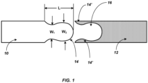
- FIG. 1 a side view of a Nitinol tube 10 and a corresponding metallic tubular component 12 is identified.
- a protruding lobe feature 14 at one end of Nitinol tube 10 is a protruding lobe feature 14 and on the metallic tubular component 12 there are corresponding lobe features 14' defining a recess or opening 16. While one lobe feature is illustrated in FIG. 1 , it should be appreciated herein that there are a plurality of such lobe features the end of the tubes 10 and 12, which are complimentary to one another, and the single lobe feature is illustrated to facilitate description of the invention.
- lobe 14 on tube 10 are complimentary to lobe 14' on tube 12 is reference to the feature that such lobes have a size and geometry that allows for the lobes to join together and provide mechanical engagement with the formation of a mechanical joint, as described further herein.
- a lobe herein may therefore be understood as a protruding feature of varying geometry that extends from one end of the tube. Accordingly, as seen in FIG. 1 , the lobe 14 extends from the tube 10 and may taper to an initial minimum width W 1 and a length L. The minimum width W 1 then expands to a second and greater width W 2 . Again, it should be understood that there are a plurality of such lobes present, and complimentary lobes of similar geometry and size on tube 12.
- the tubing herein with the now identified lobe features is tubing that may be preferably utilized in a variety of medical device applications. Accordingly, the outer diameters (OD) of the tubing that may be joined herein preferably ranges from 0.254 mm (0.010 inch) OD to 15.875 mm (0.625 inch) OD. Wall thickness preferably ranges from 0.0508 mm (0.002 inch) to 1.651 mm (0.065 inch). In addition, the OD to wall thickness ratio preferably falls in the range of 5:1 to 30:1.
- FIG. 1 therefore illustrates one exemplary lobe, thereby not falling under the scope of the claims
- the Nitinol tube 10 and corresponding metallic tubular component 12 will have a plurality of lobe features, which preferably provides 2, 3, 4, 5, or 6 lobes.
- Each lobe will preferably have a lobe length ( L ) to width ( W 1 ) aspect ratio from 0.33:1 to 10:1. See again, FIG. 1 for the location of length ( L ) and width ( W 1 ). More preferably, the number of lobes is 2-3 and the lobe length to width aspect ratio is 2:1 to 5:1. In addition, one may preferably utilize lobes that have a length to width aspect ratio from 0.33:1 to 2:1.
- the lobes in the Nitinol tubing are preferably laser cut to such preferred dimensions and any dross formation is removed from the cut tube.
- the lobes herein may be formed utilizing electrical discharge maching (EDM), computer numerical controlled (CNC) milling, abrasive water jet cutting or abrasive wire cutting.
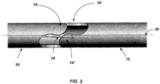
- FIG. 2 illustrates Nitinol tube 10 and corresponding metal tube 12 translating toward one another via arrow 18 in an axial direction along a common longitudinal axis (see dotted line 20 ).
- the two lobes 14 on the Nitinol tube 10 are held opened so that the tube ID at the lobe apex is larger than the OD of the original tube.
- the right tube 12 is then moved toward the left Nitinol tube 10 along the common axis 20 until the two right tube lobe apexes align with the two corresponding left piece lobes 14.
- the tubes 10 and 12 are then moved together until the complimentary lobes 14 and 14' are aligned.
- Nitinol can provide up to 8.0% strain, it is contemplated that the amount of strain on the Nitinol lobes 14 that occurs when held open is greater than 1.0 % up to 8.0%, and more preferably may fall in the range of greater than 1.0% to 6.0%.
- the strain herein is reference to the increase in length of the lobe inner stretched surface or the reduction in length of the outer compressed surface when the lobe is held open, as noted above.
- the mechanical engagement that is achieved herein by the interlocking lobes 14 and 14' is such that one may provide a mechanical joint 22 with different and targeted mechanical engagement characteristics.
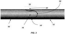
- the mechanical joint is one that has a joint length that corresponds to the length L of the identified lobe. More specifically, as illustrated in FIG. 3 , one may provide for a relatively small gap 24 to occur as between lobe 14 and tube 12, when in the mechanically engaged position. Such gap therefore will provide for some limited amount of motion as between the Nitinol tube 10 and the corresponding tubular component 12. It is contemplated that such a gap can provide for a mechanical joint with torsional flexibility (rotational freedom) of 1.0 degree to 3.0 degrees. However, it can be appreciated that when there is a flush and contacting fit between lobes 14 and 14' , there would be less than 1.0 degree of rotational freedom, or more preferably in the range of 0.1 degree up to less than 1.0 degree of such freedom.
- pull apart strength of the joints made herein with the plurality of lobe configurations such as joint 22 in FIG. 3
- YS yield strength
- the tube with the weakest cross-sectional strength will ultimately limit the maximum tensile load that the joint can sustain.
- the pull apart strength would be measured by applying a load along the tube longitudinal axis (see, e.g., 20 in FIG. 2 ) until the joint is deformed and separates or the tube material at the joint breaks.
- lobes 26 and 28 which may be understood as extending from the end of two tube sections, one being Nitinol, are shown in their engaged and interlocked position.
- lobe geometry 26 is preferably engaged via an initial axial movement (see arrow 30 ) followed by a rotational or twist motion (see arrow 32 ) of the respective tube portions that are to be mechanically joined together.
- This design allows the use of higher aspect ratio lobes without increasing the overall joint length. This in turn reduces the strain required of the Nitinol lobe during snap assembly.
- mechanical joining herein can be achieved by a variety of assembly techniques.
- mechanical engagement or formation of the mechanical joint can be achieved by translating the tubes together on a longitudinal axis.
- the tubes may be joined together by movement on an axis that is transverse to the longitudinal axis.
- the tubes may also be joined together by a hinging type motion (i.e. the tubes are initially connected and then moved towards one another about a rotational axis).
- FIG. 5 illustrates a further preferred geometry and size for the lobes herein.
- the end portion of tube 34 contains a plurality of lobes 36 which have a width W 3 at the end of the tube and a length L from the end of the tube, such that they define a relatively low length to width ratio.
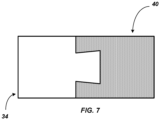
- the end portion of tube 40 contains a corresponding plurality of lobes with the same lobe geometry and accordingly, a mating recess portion 38 for lobe 36.
- such relatively low length ( L ) to width ( W 3 ) aspect ratio is in the range of 0.33:1 to 2:1.
- such lobes may have a geometry that may be described as an isosceles trapezoidal configuration, where the sides forming the protruding lobes are equal in length.
- tube 40 made of Nitinol, with its corresponding lobe geometry, is such that the lobes defining recess 38 may be again be held open (see arrows 42 ) so that the lobe 36 may be inserted into recess 38 while tubes 34 and 40 move towards one another until the lobes on tube 40 are released and snap inward to their original position. See FIGS. 6 and 7 .
- the holding open of the Nitinol lobes described in the various assembly procedures may be performed as a separate step prior to the assembly of the two tubes, or may be performed as a part of the assembly through the use of guiding assembly fixtures or by creating guiding features on the corresponding lobe geometries.
- the formation and use of the aforementioned lobes and the formation of the mechanical joint as between Nitinol and another tubular component is such that welding is avoided.
- the use of an intermediate tubular component made of compatible alloys is also not required.
- the joint formed here is such that it can be understood as a joint that is self-aligning upon assembly. No sheath or internal alignment wire is required for assembly or in service.
- the mechanical joining herein makes effective use of the superelasticity of Nitinol and forms a joint with the same OD and ID size as the Nitinol tube.
- the mechanical joining may rely upon axial engagement, movement on an axis that is transverse to the longitudinal axis, by axial engagement with rotation or twisting of the tubular components or by a hinging motion.
- the superelastic recovery of the Nitinol provides formation of the identified joint where the Nitinol is initially deformed and then permitted to recover to its original shape.
- the present invention provides a more practical approach to join Nitinol tubing to other metallic tubing.
- the Nitinol tube 10 and the corresponding lobes 14 can be selected from a superelastic Nitinol alloy that provides the shape-memory alloy effect under desirable processing temperature conditions. Accordingly, the Nitinol tube 10 and lobes 14 herein can be cooled to a relatively low temperature so that the Nitinol alloy itself becomes martensitic. Such temperature may preferably be at or below - 30 °C, more preferably in the range of -50 °C to -30 °C. This temperature range is contemplated to provide for the preferred Nitinol alloy the temperature where the alloy, as noted, will transform to the martensite structure.
- the lobes 14 When in this state, the lobes 14 can be deformed by expanding the lobes outwardly, e.g., over a conical mandrel. In effect, this then will increase the outer diameter of the tube 10 at the lobe location. The expanded lobes 14 can then be aligned and placed over the openings 16 in the metallic tubular component 12. Upon application of heat, the expanded lobes 14 will return to their room temperature shape by the shape memory effect, where the Nitinol undergoes a change in crystal structure and reverts to austenite and recovers it previous shape. As a consequence, the Nitinol lobes can engage and again form a mechanical joint as generally shown in FIG. 3 .
- Such heating may preferably be at a temperature of greater than or equal to 0 °C, more preferably in the range of 0 °C to 42 °C. As noted, for the selected Nitinol alloy, such temperatures will now conveniently transform the alloy to the austenite structure.
- the above described deformation of the lobes illustrated in FIGS. 1 and 3 utilizing the shape-memory effect of the Nitinol alloy can similarly be applied to the lobes shown on Nitinol tube 40 illustrated in FIG. 5 . More specifically, upon cooling as noted above, the lobes on Nitinol tube 40 may be deformed outwardly prior to insertion of the metallic tube 34. Such outward deformation is shown generally by arrow 42 in FIG. 5 . Then, after insertion of lobe 36 into mating recess portion 38 on the Nitinol tube 40, the Nitinol lobes may be heated as noted above and return to their original shape and mechanically engage tube 34 as shown generally in FIG. 7 .
- one may provide a first Nitinol tube where the tube includes an end portion and a plurality of first protruding lobes in a first position extending from the end portion, wherein the lobes have a two-way shape memory capability and the lobes are cooled and undergo a martensitic phase change where the cooled lobes are then expanded outward from their first position to an expanded second position.
- a second tubular metallic component is provided having an end portion and a plurality of second protruding lobes extending from said second tube end portion, including openings configured to engage with said expanded lobes on the Nitinol tube.
- Nitinol tubes with the expanded lobes are then positioned such that the lobes align with the openings in the second tubular metallic component.
- the expanded Nitinol lobes are then heated and return to their first position and mechanically engage with the second tubular metallic component.
Landscapes
- Engineering & Computer Science (AREA)
- Mechanical Engineering (AREA)
- General Engineering & Computer Science (AREA)
- Earth Drilling (AREA)
Description
- The present invention relates to mechanical joining of Nickel Titanium tubes, also known as Nitinol, to other tubular components. Such mechanical joining may be achieved using Nitinol's superelastic behavior by interpenetration of lobe features between the respective tubes which may be achieved by translating the tubes together on a longitudinal axis, a transverse axis, by a combination of translation and rotational motion or by a hinging motion. Mechanical joining may also be achieved using Nitinol's shape memory behavior by cooling the Nitinol tube, deforming the lobe features, positioning the lobe features in the desired penetrated position then heating the Nitinol so it returns to its original shape to achieve an interpenetrated joint.
- Nitinol is an alloy of approximately 50% Nickel and 50% Titanium. The difference of electronegativity between the two elements (Ni = 1.9 and Ti = 1.54 Pauling electronegativity) is large enough that they violate the Hume Rothery solubility criteria and combine when melted and cooled to room temperature as a NiTi body centered cubic intermetallic compound in which every nickel atom is surrounded by a titanium atom and vice versa. This gives the material unusual mechanical behaviors, including what is referred to as superelasticity. Such superelasticity is a pseudoelastic response to an applied stress caused by a phase transformation between the austenitic and martensitic phases of a crystal. The material composition makes welding of nitinol to other engineering materials problematic, since either the Nickel or the Titanium will form brittle intermetallic compounds with many other metals and their alloys, including stainless steels.
- On some device designs, nitinol tubing is required to provide flexibility at a specific location along a long drive tube. Since nitinol is relatively expensive, it is logical to use the nitinol only where it is needed for flexibility and join it to a relatively lower cost tube, like stainless steel, that would provide most of the remaining length of the drive tube. Historically this has been accomplished by welding the tube ends together.
- One successful welding method for joining Nitinol to stainless steel involves welding the Nitinol component to an intermediate component made of Nickel, Cobalt or Tantalum and their alloys which are compatible with both metals. This approach involves the additional cost of the intermediate metal component as well as the cost of welding. For relatively simple product forms like wire, this may be a cost effective approach. For more complex product forms like tubing, the cost and lead time for the intermediate metal component, as well as the more complex tube welding methods, make this approach less attractive.
- Accordingly, a need remains for a method of joining Nitinol tubing to other tubular structures, made of materials other than Nitinol, that would avoid welding procedures and the need for an intermediate metal component, and other associated problems.
-
US 2018/093070 A1 discloses a method for joining a Nitinol tube and a corresponding non-Nitinol tube according to the preamble of claim 1. - A method of forming a mechanical joint between a Nitinol tube and a corresponding tubular component of a metallic material other than Nitinol is disclosed in appended claim 1.
- The objects, features and advantages of the present invention will be apparent from the following detailed descriptions of the preferred aspects of the invention in conjunction with reference to the following drawings, where:
-
FIG. 1 illustrates an exemplary lobe structure in accordance with the present invention. -
FIG. 2 illustrates a Nitinol tube and corresponding metal tube as they are configured for mechanical engagement. -
FIG. 3 illustrates a Nitinol tube engage with a corresponding metal tube and the formation of a mechanical joint between such tubing. -
FIG. 4 illustrates a lobe geometry that is engaged by an initial axial movement followed by a rotational or twist motion. -
FIG. 5 illustrates a further preferred geometry for the lobes disclosed herein for placement on Nitinol tubing. -
FIG. 6 illustrates engagement of the lobes illustrated 5 inFIG. 5 . -
FIG. 7 illustrates the formation of a mechanical joint between the lobes illustrated inFIG. 5 . - The present invention provides a structure and associated method for the mechanical joining of Nitinol tubing to other metallic tubular components. Reference to Nitinol herein should be understood as a metal alloy containing Nickel and Titanium in approximately equal amounts. The other tubular components that may be utilized herein include, but are not limited to any metallic based tubing, and in particular metal tubing that does not utilize Nitinol. Accordingly, such metallic based tubing may include stainless steel, such as 304 and 316 stainless steel, precipitation hardenable (PH) stainless steel such as 17-7 PH™, cobalt alloys such as MP35N, and nickel alloys such as InconelTM 600, 625 and 718.
- The tubular components herein are provided with a plurality of lobe features extending from the end of the tubes. With reference to
FIG. 1 , a side view of a Nitinoltube 10 and a corresponding metallictubular component 12 is identified. As can be seen, at one end of Nitinoltube 10 is a protrudinglobe feature 14 and on the metallictubular component 12 there are corresponding lobe features 14' defining a recess or opening 16. While one lobe feature is illustrated inFIG. 1 , it should be appreciated herein that there are a plurality of such lobe features the end of thetubes lobe 14 ontube 10 are complimentary to lobe 14' ontube 12 is reference to the feature that such lobes have a size and geometry that allows for the lobes to join together and provide mechanical engagement with the formation of a mechanical joint, as described further herein. - A lobe herein may therefore be understood as a protruding feature of varying geometry that extends from one end of the tube. Accordingly, as seen in
FIG. 1 , thelobe 14 extends from thetube 10 and may taper to an initial minimum width W1 and a length L. The minimum width W1 then expands to a second and greater width W2 . Again, it should be understood that there are a plurality of such lobes present, and complimentary lobes of similar geometry and size ontube 12. - The tubing herein with the now identified lobe features is tubing that may be preferably utilized in a variety of medical device applications. Accordingly, the outer diameters (OD) of the tubing that may be joined herein preferably ranges from 0.254 mm (0.010 inch) OD to 15.875 mm (0.625 inch) OD. Wall thickness preferably ranges from 0.0508 mm (0.002 inch) to 1.651 mm (0.065 inch). In addition, the OD to wall thickness ratio preferably falls in the range of 5:1 to 30:1.
- While
FIG. 1 therefore illustrates one exemplary lobe, thereby not falling under the scope of the claims, it should now be appreciated that the Nitinoltube 10 and corresponding metallictubular component 12 will have a plurality of lobe features, which preferably provides 2, 3, 4, 5, or 6 lobes. Each lobe will preferably have a lobe length (L) to width (W1 ) aspect ratio from 0.33:1 to 10:1. See again,FIG. 1 for the location of length (L) and width (W1 ). More preferably, the number of lobes is 2-3 and the lobe length to width aspect ratio is 2:1 to 5:1. In addition, one may preferably utilize lobes that have a length to width aspect ratio from 0.33:1 to 2:1. The lobes in the Nitinol tubing are preferably laser cut to such preferred dimensions and any dross formation is removed from the cut tube. However, in the broad context of the present disclosure, the lobes herein may be formed utilizing electrical discharge maching (EDM), computer numerical controlled (CNC) milling, abrasive water jet cutting or abrasive wire cutting. - Attention is next directed to
FIG. 2 which illustrates Nitinoltube 10 andcorresponding metal tube 12 translating toward one another viaarrow 18 in an axial direction along a common longitudinal axis (see dotted line 20). The twolobes 14 on the Nitinoltube 10 are held opened so that the tube ID at the lobe apex is larger than the OD of the original tube. Theright tube 12 is then moved toward the left Nitinoltube 10 along thecommon axis 20 until the two right tube lobe apexes align with the two correspondingleft piece lobes 14. Thetubes complimentary lobes 14 and 14' are aligned. At this point thelobes 14 are released from their open position allowing them to move inwardly to their original position. This results in what may described as a snap fit which then serves to lock thelobes 14 and 14' together. SeeFIG. 3 . As Nitinol can provide up to 8.0% strain, it is contemplated that the amount of strain on the Nitinollobes 14 that occurs when held open is greater than 1.0 % up to 8.0%, and more preferably may fall in the range of greater than 1.0% to 6.0%. The strain herein is reference to the increase in length of the lobe inner stretched surface or the reduction in length of the outer compressed surface when the lobe is held open, as noted above. - With reference to
FIG. 3 , it should be appreciated the mechanical engagement that is achieved herein by the interlockinglobes 14 and 14' is such that one may provide amechanical joint 22 with different and targeted mechanical engagement characteristics. As illustrated, the mechanical joint is one that has a joint length that corresponds to the length L of the identified lobe. More specifically, as illustrated inFIG. 3 , one may provide for a relativelysmall gap 24 to occur as betweenlobe 14 andtube 12, when in the mechanically engaged position. Such gap therefore will provide for some limited amount of motion as between theNitinol tube 10 and the correspondingtubular component 12. It is contemplated that such a gap can provide for a mechanical joint with torsional flexibility (rotational freedom) of 1.0 degree to 3.0 degrees. However, it can be appreciated that when there is a flush and contacting fit betweenlobes 14 and 14', there would be less than 1.0 degree of rotational freedom, or more preferably in the range of 0.1 degree up to less than 1.0 degree of such freedom. - Furthermore, with respect to what may be understood as the pull apart strength of the joints made herein with the plurality of lobe configurations, such as joint 22 in
FIG. 3 , it is contemplated that such pull apart strength will be up to one-half of the yield strength (YS) of the tube made of the relatively weaker material. It should be noted that the tube with the weakest cross-sectional strength will ultimately limit the maximum tensile load that the joint can sustain. The pull apart strength would be measured by applying a load along the tube longitudinal axis (see, e.g., 20 inFIG. 2 ) until the joint is deformed and separates or the tube material at the joint breaks. - While the above describes the use of translating axial joining of
Nitinol tube 10 andcorresponding tube 12, i.e. with reference again toFIG. 2 , movement of thetube longitudinal axis 20, the present invention also contemplates the use of a lobe geometry that would utilize such axial movement along with a rotational or twist motion. More specifically, with reference toFIG. 4 ,lobes such lobe geometry 26 is preferably engaged via an initial axial movement (see arrow 30) followed by a rotational or twist motion (see arrow 32) of the respective tube portions that are to be mechanically joined together. This design allows the use of higher aspect ratio lobes without increasing the overall joint length. This in turn reduces the strain required of the Nitinol lobe during snap assembly. - It should therefore now be appreciated that the mechanical joining herein can be achieved by a variety of assembly techniques. As noted, mechanical engagement or formation of the mechanical joint can be achieved by translating the tubes together on a longitudinal axis. In addition, it should be appreciated that the tubes may be joined together by movement on an axis that is transverse to the longitudinal axis. In addition, the tubes may also be joined together by a hinging type motion (i.e. the tubes are initially connected and then moved towards one another about a rotational axis). With respect to the use of a hinging motion, such would apply where there is an odd number of lobes on each tube and wherein, e.g., one lobe on the Nitinol tube is inserted at an angle into a corresponding recess on the metallic tube. Once inserted, the remaining lobes are then moved together by a hinging motion until all of the lobes have engaged into their corresponding recess locations.
- Reference is next directed to
FIG. 5 , which illustrates a further preferred geometry and size for the lobes herein. As illustrated, the end portion oftube 34 contains a plurality oflobes 36 which have a width W3 at the end of the tube and a length L from the end of the tube, such that they define a relatively low length to width ratio. The end portion oftube 40 contains a corresponding plurality of lobes with the same lobe geometry and accordingly, amating recess portion 38 forlobe 36. Preferably, such relatively low length (L) to width (W3 ) aspect ratio is in the range of 0.33:1 to 2:1. As can also be seen, such lobes may have a geometry that may be described as an isosceles trapezoidal configuration, where the sides forming the protruding lobes are equal in length. In this particular embodiment, it can again be appreciated thattube 40, made of Nitinol, with its corresponding lobe geometry, is such that thelobes defining recess 38 may be again be held open (see arrows 42) so that thelobe 36 may be inserted intorecess 38 whiletubes tube 40 are released and snap inward to their original position. SeeFIGS. 6 and7 . - It should be noted that the holding open of the Nitinol lobes described in the various assembly procedures may be performed as a separate step prior to the assembly of the two tubes, or may be performed as a part of the assembly through the use of guiding assembly fixtures or by creating guiding features on the corresponding lobe geometries.
- It can now be appreciated that there are a number of benefits and advantages to the present invention. Among other things, the formation and use of the aforementioned lobes and the formation of the mechanical joint as between Nitinol and another tubular component is such that welding is avoided. In addition, the use of an intermediate tubular component made of compatible alloys is also not required. Furthermore, the joint formed here is such that it can be understood as a joint that is self-aligning upon assembly. No sheath or internal alignment wire is required for assembly or in service.
- Furthermore, the mechanical joining herein makes effective use of the superelasticity of Nitinol and forms a joint with the same OD and ID size as the Nitinol tube. As noted above, the mechanical joining may rely upon axial engagement, movement on an axis that is transverse to the longitudinal axis, by axial engagement with rotation or twisting of the tubular components or by a hinging motion. The superelastic recovery of the Nitinol provides formation of the identified joint where the Nitinol is initially deformed and then permitted to recover to its original shape. As Nitinol tubing is used in a variety of medical devices (e.g. flexible drives, catheters, stent delivery systems and elastic needles), the present invention provides a more practical approach to join Nitinol tubing to other metallic tubing.
- In addition to the above, and considering again
FIGS. 1 and2 , theNitinol tube 10 and the correspondinglobes 14 can be selected from a superelastic Nitinol alloy that provides the shape-memory alloy effect under desirable processing temperature conditions. Accordingly, theNitinol tube 10 andlobes 14 herein can be cooled to a relatively low temperature so that the Nitinol alloy itself becomes martensitic. Such temperature may preferably be at or below - 30 °C, more preferably in the range of -50 °C to -30 °C. This temperature range is contemplated to provide for the preferred Nitinol alloy the temperature where the alloy, as noted, will transform to the martensite structure. When in this state, thelobes 14 can be deformed by expanding the lobes outwardly, e.g., over a conical mandrel. In effect, this then will increase the outer diameter of thetube 10 at the lobe location. The expandedlobes 14 can then be aligned and placed over theopenings 16 in the metallictubular component 12. Upon application of heat, the expandedlobes 14 will return to their room temperature shape by the shape memory effect, where the Nitinol undergoes a change in crystal structure and reverts to austenite and recovers it previous shape. As a consequence, the Nitinol lobes can engage and again form a mechanical joint as generally shown inFIG. 3 . Such heating may preferably be at a temperature of greater than or equal to 0 °C, more preferably in the range of 0 °C to 42 °C. As noted, for the selected Nitinol alloy, such temperatures will now conveniently transform the alloy to the austenite structure. - It should also be mentioned that the above described deformation of the lobes illustrated in
FIGS. 1 and3 utilizing the shape-memory effect of the Nitinol alloy can similarly be applied to the lobes shown onNitinol tube 40 illustrated inFIG. 5 . More specifically, upon cooling as noted above, the lobes onNitinol tube 40 may be deformed outwardly prior to insertion of themetallic tube 34. Such outward deformation is shown generally byarrow 42 inFIG. 5 . Then, after insertion oflobe 36 intomating recess portion 38 on theNitinol tube 40, the Nitinol lobes may be heated as noted above and return to their original shape and mechanically engagetube 34 as shown generally inFIG. 7 . - Accordingly, one may provide a first Nitinol tube where the tube includes an end portion and a plurality of first protruding lobes in a first position extending from the end portion, wherein the lobes have a two-way shape memory capability and the lobes are cooled and undergo a martensitic phase change where the cooled lobes are then expanded outward from their first position to an expanded second position. A second tubular metallic component is provided having an end portion and a plurality of second protruding lobes extending from said second tube end portion, including openings configured to engage with said expanded lobes on the Nitinol tube. The Nitinol tubes with the expanded lobes are then positioned such that the lobes align with the openings in the second tubular metallic component. The expanded Nitinol lobes are then heated and return to their first position and mechanically engage with the second tubular metallic component.
Claims (10)
- A method of forming a mechanical joint between a Nitinol tube and a corresponding tubular component of a metallic material other than Nitinol comprising:providing a first Nitinol tube (10) wherein said tube includes a first end portion and a plurality of first protruding lobes (14) extending from said first end portion;providing a second tubular component (12) of a metallic material other than Nitinol having a second end portion and a plurality of second protruding lobes (14') extending from said second end portion, wherein said second protruding lobes (14') are complimentary in size and geometry with the first protruding lobes (14);mechanically engaging said first end portion having said first plurality of lobes (14) with said second end portion having said second plurality of lobes (14') wherein said lobes engage and form a mechanical joint;wherein said plurality of lobes (14) are in a first position on said first Nitinol tube (10) characterised in that, said Nitinol lobes are cooled and said cooled lobes are expanded to a second position and said expanded lobes are aligned with said end portion of said second tubular component (12) and said expanded lobes are then heated and return to said first position and form said mechanical joint.
- The method of claim 1 wherein said plurality of lobes (14) extending from said first end portion on said Nitinol tube (10) comprise an initial minimum width W1 and a length L, wherein the length to width aspect ratio of 0 33:1 to 10:1.
- The method of claim 1 wherein the plurality of lobes (14) extending form said end portion on said Nitinol tube (10) comprises 2, 3, 4, 5 or 6 lobes.
- The method of claim 1 wherein said Nitinol tube (10) has an outer diameter (OD) of 0.254 mm to 15.875 mm.
- rhe method of claim 1 wherein said Nitinol tube (10) has a wall thickness of 0.051 mm to 1.651 mm.
- The method of claim 1 wherein the outer diameter (OD) to wall thickness ratio is 5:1 to 30:1.
- The method of claim 1 wherein said lobe has a length L and a width at the end of the tube (W3) such that the length (L) to width (Ws) ratio is in the range of 0.33:1 to 2:1.
- The method of claim 1 wherein said mechanical engagement of said first Nitinol tube (10) end portion with said second metallic tubular component includes a strain on said Nitinol lobes of greater than 1.0% up to 8.0%.
- The method of claim 1 wherein said mechanical joint comprises a gap (24) between the plurality of lobes (14) and the second tubular component (12), thereby achieving a torsional flexibility of .1 degree up to less than 1.0 degree.
- The method of claim 1 wherein said mechanical joint comprises a gap (24) between the plurality of lobes (14) and the second tubular component (12), thereby achieving a torsional flexibility of 1.0 degree to 3.0 degrees.
Applications Claiming Priority (3)
| Application Number | Priority Date | Filing Date | Title |
|---|---|---|---|
| US201862680902P | 2018-06-05 | 2018-06-05 | |
| US16/222,312 US11885442B2 (en) | 2017-12-15 | 2018-12-17 | Mechanical joining of nitinol tubes |
| PCT/US2019/035333 WO2019236543A1 (en) | 2018-06-05 | 2019-06-04 | Mechanical joining of nitinol tubes |
Publications (3)
| Publication Number | Publication Date |
|---|---|
| EP3803137A1 EP3803137A1 (en) | 2021-04-14 |
| EP3803137A4 EP3803137A4 (en) | 2022-03-02 |
| EP3803137B1 true EP3803137B1 (en) | 2025-02-12 |
Family
ID=68770611
Family Applications (1)
| Application Number | Title | Priority Date | Filing Date |
|---|---|---|---|
| EP19815026.0A Active EP3803137B1 (en) | 2018-06-05 | 2019-06-04 | Mechanical joining of nitinol tubes |
Country Status (2)
| Country | Link |
|---|---|
| EP (1) | EP3803137B1 (en) |
| WO (1) | WO2019236543A1 (en) |
Family Cites Families (7)
| Publication number | Priority date | Publication date | Assignee | Title |
|---|---|---|---|---|
| US4433567A (en) * | 1981-11-12 | 1984-02-28 | Grumman Aerospace Corporation | Method for working holes |
| US6352385B1 (en) * | 2000-07-31 | 2002-03-05 | General Electric Company | Mechanical coupling for cooperating rotatable members |
| US7625364B2 (en) * | 2003-05-27 | 2009-12-01 | Cardia, Inc. | Flexible center connection for occlusion device |
| EP2299917A1 (en) * | 2008-06-10 | 2011-03-30 | Sonoma Orthopedic Products, Inc. | Fracture fixation device, tools and methods |
| DE102009042491A1 (en) * | 2009-05-29 | 2010-12-02 | Aesculap Ag | Surgical instrument for use as shaver, has zone arranged in area of distal section, and drive element rotatably supported in shaft, where flexible section of element exhibits length in axial direction, which corresponds to length of zone |
| US9539670B2 (en) * | 2010-05-25 | 2017-01-10 | Creganna-Tactx Medical | Joint for tubular materials |
| US11007345B2 (en) * | 2016-10-05 | 2021-05-18 | Orbusneich Medical Pte. Ltd. | Modular vascular catheter |
-
2019
- 2019-06-04 WO PCT/US2019/035333 patent/WO2019236543A1/en not_active Ceased
- 2019-06-04 EP EP19815026.0A patent/EP3803137B1/en active Active
Also Published As
| Publication number | Publication date |
|---|---|
| EP3803137A4 (en) | 2022-03-02 |
| EP3803137A1 (en) | 2021-04-14 |
| WO2019236543A1 (en) | 2019-12-12 |
Similar Documents
| Publication | Publication Date | Title |
|---|---|---|
| US8137292B2 (en) | Elongated medical device for intracorporal use | |
| EP2408508B1 (en) | Guide wire with core having welded wire segments | |
| AU718562B2 (en) | Clad shape memory alloy composite structure and method | |
| US9056351B2 (en) | Stent with improved flexibility and method for making same | |
| JPH1142283A (en) | Stent | |
| WO2004075941A1 (en) | Composite medical device | |
| EP3213861B1 (en) | Method of joining titanium and titanium-based alloys to ferrous metals using tantalum | |
| CN107666936A (en) | For improving the mechanism across the stiffness transition at different-metal material welding junction surface | |
| WO2015020724A1 (en) | Guide wire with core made from low-modulus cobalt-chromium alloy | |
| US8569625B2 (en) | Joined dissimilar materials | |
| US11835158B2 (en) | Mechanical joining of Nitinol tubes | |
| WO2020247650A1 (en) | Mechanical joining of nitinol tubes | |
| US11885442B2 (en) | Mechanical joining of nitinol tubes | |
| EP3803137A1 (en) | Mechanical joining of nitinol tubes | |
| US10376944B2 (en) | Pipe joining body, treatment tool, and joining method | |
| US20160279391A1 (en) | Solid state methods for joining dissimilar metal guidewire segments without the use of tertiary material | |
| US20200197669A1 (en) | Niobium coated sleeves for joining nickel titanium shape memory components for guidewires | |
| US20190255639A1 (en) | Niobium coated sleeves for joining nickel titanium shape memory components for medical devices | |
| EP4132371A1 (en) | Composite suture needles having elastically deformable sections | |
| JP2022021277A (en) | Guide wire and manufacturing method for the same | |
| JP2018119657A (en) | Connection structure and manufacturing method of connection structure | |
| EP2960002B1 (en) | Methods for dissimilar material welding | |
| JP2023104105A (en) | Bond and its manufacturing method |
Legal Events
| Date | Code | Title | Description |
|---|---|---|---|
| STAA | Information on the status of an ep patent application or granted ep patent |
Free format text: STATUS: THE INTERNATIONAL PUBLICATION HAS BEEN MADE |
|
| PUAI | Public reference made under article 153(3) epc to a published international application that has entered the european phase |
Free format text: ORIGINAL CODE: 0009012 |
|
| STAA | Information on the status of an ep patent application or granted ep patent |
Free format text: STATUS: REQUEST FOR EXAMINATION WAS MADE |
|
| 17P | Request for examination filed |
Effective date: 20201216 |
|
| AK | Designated contracting states |
Kind code of ref document: A1 Designated state(s): AL AT BE BG CH CY CZ DE DK EE ES FI FR GB GR HR HU IE IS IT LI LT LU LV MC MK MT NL NO PL PT RO RS SE SI SK SM TR |
|
| AX | Request for extension of the european patent |
Extension state: BA ME |
|
| DAV | Request for validation of the european patent (deleted) | ||
| DAX | Request for extension of the european patent (deleted) | ||
| A4 | Supplementary search report drawn up and despatched |
Effective date: 20220202 |
|
| RIC1 | Information provided on ipc code assigned before grant |
Ipc: B21D 39/03 20060101ALN20220127BHEP Ipc: F16B 7/04 20060101ALI20220127BHEP Ipc: C21D 9/00 20060101ALI20220127BHEP Ipc: B21D 41/02 20060101ALI20220127BHEP Ipc: B21D 39/04 20060101ALI20220127BHEP Ipc: B21D 35/00 20060101ALI20220127BHEP Ipc: F16B 7/00 20060101AFI20220127BHEP |
|
| GRAP | Despatch of communication of intention to grant a patent |
Free format text: ORIGINAL CODE: EPIDOSNIGR1 |
|
| STAA | Information on the status of an ep patent application or granted ep patent |
Free format text: STATUS: GRANT OF PATENT IS INTENDED |
|
| RIC1 | Information provided on ipc code assigned before grant |
Ipc: B21D 39/03 20060101ALN20240730BHEP Ipc: F16B 7/04 20060101ALI20240730BHEP Ipc: C21D 9/00 20060101ALI20240730BHEP Ipc: B21D 41/02 20060101ALI20240730BHEP Ipc: B21D 39/04 20060101ALI20240730BHEP Ipc: B21D 35/00 20060101ALI20240730BHEP Ipc: F16B 7/00 20060101AFI20240730BHEP |
|
| INTG | Intention to grant announced |
Effective date: 20240826 |
|
| GRAS | Grant fee paid |
Free format text: ORIGINAL CODE: EPIDOSNIGR3 |
|
| GRAA | (expected) grant |
Free format text: ORIGINAL CODE: 0009210 |
|
| STAA | Information on the status of an ep patent application or granted ep patent |
Free format text: STATUS: THE PATENT HAS BEEN GRANTED |
|
| AK | Designated contracting states |
Kind code of ref document: B1 Designated state(s): AL AT BE BG CH CY CZ DE DK EE ES FI FR GB GR HR HU IE IS IT LI LT LU LV MC MK MT NL NO PL PT RO RS SE SI SK SM TR |
|
| REG | Reference to a national code |
Ref country code: GB Ref legal event code: FG4D |
|
| REG | Reference to a national code |
Ref country code: CH Ref legal event code: EP |
|
| REG | Reference to a national code |
Ref country code: DE Ref legal event code: R096 Ref document number: 602019065858 Country of ref document: DE |
|
| P01 | Opt-out of the competence of the unified patent court (upc) registered |
Free format text: CASE NUMBER: APP_4333/2025 Effective date: 20250127 |
|
| REG | Reference to a national code |
Ref country code: IE Ref legal event code: FG4D |
|
| REG | Reference to a national code |
Ref country code: NL Ref legal event code: MP Effective date: 20250212 |
|
| PG25 | Lapsed in a contracting state [announced via postgrant information from national office to epo] |
Ref country code: RS Free format text: LAPSE BECAUSE OF FAILURE TO SUBMIT A TRANSLATION OF THE DESCRIPTION OR TO PAY THE FEE WITHIN THE PRESCRIBED TIME-LIMIT Effective date: 20250512 |
|
| PG25 | Lapsed in a contracting state [announced via postgrant information from national office to epo] |
Ref country code: FI Free format text: LAPSE BECAUSE OF FAILURE TO SUBMIT A TRANSLATION OF THE DESCRIPTION OR TO PAY THE FEE WITHIN THE PRESCRIBED TIME-LIMIT Effective date: 20250212 |
|
| PG25 | Lapsed in a contracting state [announced via postgrant information from national office to epo] |
Ref country code: PL Free format text: LAPSE BECAUSE OF FAILURE TO SUBMIT A TRANSLATION OF THE DESCRIPTION OR TO PAY THE FEE WITHIN THE PRESCRIBED TIME-LIMIT Effective date: 20250212 |
|
| PGFP | Annual fee paid to national office [announced via postgrant information from national office to epo] |
Ref country code: DE Payment date: 20250402 Year of fee payment: 7 |
|
| PG25 | Lapsed in a contracting state [announced via postgrant information from national office to epo] |
Ref country code: ES Free format text: LAPSE BECAUSE OF FAILURE TO SUBMIT A TRANSLATION OF THE DESCRIPTION OR TO PAY THE FEE WITHIN THE PRESCRIBED TIME-LIMIT Effective date: 20250212 |
|
| PGFP | Annual fee paid to national office [announced via postgrant information from national office to epo] |
Ref country code: GB Payment date: 20250401 Year of fee payment: 7 |
|
| REG | Reference to a national code |
Ref country code: LT Ref legal event code: MG9D |
|
| PG25 | Lapsed in a contracting state [announced via postgrant information from national office to epo] |
Ref country code: NO Free format text: LAPSE BECAUSE OF FAILURE TO SUBMIT A TRANSLATION OF THE DESCRIPTION OR TO PAY THE FEE WITHIN THE PRESCRIBED TIME-LIMIT Effective date: 20250512 Ref country code: IS Free format text: LAPSE BECAUSE OF FAILURE TO SUBMIT A TRANSLATION OF THE DESCRIPTION OR TO PAY THE FEE WITHIN THE PRESCRIBED TIME-LIMIT Effective date: 20250612 |
|
| PG25 | Lapsed in a contracting state [announced via postgrant information from national office to epo] |
Ref country code: NL Free format text: LAPSE BECAUSE OF FAILURE TO SUBMIT A TRANSLATION OF THE DESCRIPTION OR TO PAY THE FEE WITHIN THE PRESCRIBED TIME-LIMIT Effective date: 20250212 |
|
| PG25 | Lapsed in a contracting state [announced via postgrant information from national office to epo] |
Ref country code: HR Free format text: LAPSE BECAUSE OF FAILURE TO SUBMIT A TRANSLATION OF THE DESCRIPTION OR TO PAY THE FEE WITHIN THE PRESCRIBED TIME-LIMIT Effective date: 20250212 |
|
| PG25 | Lapsed in a contracting state [announced via postgrant information from national office to epo] |
Ref country code: PT Free format text: LAPSE BECAUSE OF FAILURE TO SUBMIT A TRANSLATION OF THE DESCRIPTION OR TO PAY THE FEE WITHIN THE PRESCRIBED TIME-LIMIT Effective date: 20250612 Ref country code: LV Free format text: LAPSE BECAUSE OF FAILURE TO SUBMIT A TRANSLATION OF THE DESCRIPTION OR TO PAY THE FEE WITHIN THE PRESCRIBED TIME-LIMIT Effective date: 20250212 |
|
| PGFP | Annual fee paid to national office [announced via postgrant information from national office to epo] |
Ref country code: FR Payment date: 20250401 Year of fee payment: 7 |
|
| PG25 | Lapsed in a contracting state [announced via postgrant information from national office to epo] |
Ref country code: BG Free format text: LAPSE BECAUSE OF FAILURE TO SUBMIT A TRANSLATION OF THE DESCRIPTION OR TO PAY THE FEE WITHIN THE PRESCRIBED TIME-LIMIT Effective date: 20250212 Ref country code: GR Free format text: LAPSE BECAUSE OF FAILURE TO SUBMIT A TRANSLATION OF THE DESCRIPTION OR TO PAY THE FEE WITHIN THE PRESCRIBED TIME-LIMIT Effective date: 20250513 |
|
| REG | Reference to a national code |
Ref country code: AT Ref legal event code: MK05 Ref document number: 1766269 Country of ref document: AT Kind code of ref document: T Effective date: 20250212 |
|
| PG25 | Lapsed in a contracting state [announced via postgrant information from national office to epo] |
Ref country code: SE Free format text: LAPSE BECAUSE OF FAILURE TO SUBMIT A TRANSLATION OF THE DESCRIPTION OR TO PAY THE FEE WITHIN THE PRESCRIBED TIME-LIMIT Effective date: 20250212 |
|
| PG25 | Lapsed in a contracting state [announced via postgrant information from national office to epo] |
Ref country code: SM Free format text: LAPSE BECAUSE OF FAILURE TO SUBMIT A TRANSLATION OF THE DESCRIPTION OR TO PAY THE FEE WITHIN THE PRESCRIBED TIME-LIMIT Effective date: 20250212 |
|
| PG25 | Lapsed in a contracting state [announced via postgrant information from national office to epo] |
Ref country code: DK Free format text: LAPSE BECAUSE OF FAILURE TO SUBMIT A TRANSLATION OF THE DESCRIPTION OR TO PAY THE FEE WITHIN THE PRESCRIBED TIME-LIMIT Effective date: 20250212 |
|
| PG25 | Lapsed in a contracting state [announced via postgrant information from national office to epo] |
Ref country code: IT Free format text: LAPSE BECAUSE OF FAILURE TO SUBMIT A TRANSLATION OF THE DESCRIPTION OR TO PAY THE FEE WITHIN THE PRESCRIBED TIME-LIMIT Effective date: 20250212 |
|
| PG25 | Lapsed in a contracting state [announced via postgrant information from national office to epo] |
Ref country code: AT Free format text: LAPSE BECAUSE OF FAILURE TO SUBMIT A TRANSLATION OF THE DESCRIPTION OR TO PAY THE FEE WITHIN THE PRESCRIBED TIME-LIMIT Effective date: 20250212 |
|
| PGFP | Annual fee paid to national office [announced via postgrant information from national office to epo] |
Ref country code: CH Payment date: 20250701 Year of fee payment: 7 |
|
| PG25 | Lapsed in a contracting state [announced via postgrant information from national office to epo] |
Ref country code: EE Free format text: LAPSE BECAUSE OF FAILURE TO SUBMIT A TRANSLATION OF THE DESCRIPTION OR TO PAY THE FEE WITHIN THE PRESCRIBED TIME-LIMIT Effective date: 20250212 Ref country code: CZ Free format text: LAPSE BECAUSE OF FAILURE TO SUBMIT A TRANSLATION OF THE DESCRIPTION OR TO PAY THE FEE WITHIN THE PRESCRIBED TIME-LIMIT Effective date: 20250212 |
|
| PG25 | Lapsed in a contracting state [announced via postgrant information from national office to epo] |
Ref country code: RO Free format text: LAPSE BECAUSE OF FAILURE TO SUBMIT A TRANSLATION OF THE DESCRIPTION OR TO PAY THE FEE WITHIN THE PRESCRIBED TIME-LIMIT Effective date: 20250212 |
|
| PG25 | Lapsed in a contracting state [announced via postgrant information from national office to epo] |
Ref country code: SK Free format text: LAPSE BECAUSE OF FAILURE TO SUBMIT A TRANSLATION OF THE DESCRIPTION OR TO PAY THE FEE WITHIN THE PRESCRIBED TIME-LIMIT Effective date: 20250212 |
|
| REG | Reference to a national code |
Ref country code: DE Ref legal event code: R097 Ref document number: 602019065858 Country of ref document: DE |
|
| PLBE | No opposition filed within time limit |
Free format text: ORIGINAL CODE: 0009261 |
|
| STAA | Information on the status of an ep patent application or granted ep patent |
Free format text: STATUS: NO OPPOSITION FILED WITHIN TIME LIMIT |
|
| 26N | No opposition filed |
Effective date: 20251113 |
|
| PG25 | Lapsed in a contracting state [announced via postgrant information from national office to epo] |
Ref country code: MC Free format text: LAPSE BECAUSE OF FAILURE TO SUBMIT A TRANSLATION OF THE DESCRIPTION OR TO PAY THE FEE WITHIN THE PRESCRIBED TIME-LIMIT Effective date: 20250212 |
|
| PG25 | Lapsed in a contracting state [announced via postgrant information from national office to epo] |
Ref country code: LU Free format text: LAPSE BECAUSE OF NON-PAYMENT OF DUE FEES Effective date: 20250604 |
|
| REG | Reference to a national code |
Ref country code: BE Ref legal event code: MM Effective date: 20250630 |
|
| PG25 | Lapsed in a contracting state [announced via postgrant information from national office to epo] |
Ref country code: IE Free format text: LAPSE BECAUSE OF NON-PAYMENT OF DUE FEES Effective date: 20250604 |
|
| PG25 | Lapsed in a contracting state [announced via postgrant information from national office to epo] |
Ref country code: BE Free format text: LAPSE BECAUSE OF NON-PAYMENT OF DUE FEES Effective date: 20250630 |