EP3803060B1 - Shroud and seal for gas turbine engine - Google Patents
Shroud and seal for gas turbine engine Download PDFInfo
- Publication number
- EP3803060B1 EP3803060B1 EP19730080.9A EP19730080A EP3803060B1 EP 3803060 B1 EP3803060 B1 EP 3803060B1 EP 19730080 A EP19730080 A EP 19730080A EP 3803060 B1 EP3803060 B1 EP 3803060B1
- Authority
- EP
- European Patent Office
- Prior art keywords
- inner shroud
- shroud segment
- cooling channels
- cooling
- outlets
- Prior art date
- Legal status (The legal status is an assumption and is not a legal conclusion. Google has not performed a legal analysis and makes no representation as to the accuracy of the status listed.)
- Active
Links
Images

Classifications
-
- F—MECHANICAL ENGINEERING; LIGHTING; HEATING; WEAPONS; BLASTING
- F01—MACHINES OR ENGINES IN GENERAL; ENGINE PLANTS IN GENERAL; STEAM ENGINES
- F01D—NON-POSITIVE DISPLACEMENT MACHINES OR ENGINES, e.g. STEAM TURBINES
- F01D25/00—Component parts, details, or accessories, not provided for in, or of interest apart from, other groups
- F01D25/08—Cooling; Heating; Heat-insulation
- F01D25/12—Cooling
-
- F—MECHANICAL ENGINEERING; LIGHTING; HEATING; WEAPONS; BLASTING
- F01—MACHINES OR ENGINES IN GENERAL; ENGINE PLANTS IN GENERAL; STEAM ENGINES
- F01D—NON-POSITIVE DISPLACEMENT MACHINES OR ENGINES, e.g. STEAM TURBINES
- F01D9/00—Stators
- F01D9/06—Fluid supply conduits to nozzles or the like
- F01D9/065—Fluid supply or removal conduits traversing the working fluid flow, e.g. for lubrication-, cooling-, or sealing fluids
-
- F—MECHANICAL ENGINEERING; LIGHTING; HEATING; WEAPONS; BLASTING
- F01—MACHINES OR ENGINES IN GENERAL; ENGINE PLANTS IN GENERAL; STEAM ENGINES
- F01D—NON-POSITIVE DISPLACEMENT MACHINES OR ENGINES, e.g. STEAM TURBINES
- F01D11/00—Preventing or minimising internal leakage of working-fluid, e.g. between stages
- F01D11/005—Sealing means between non relatively rotating elements
-
- F—MECHANICAL ENGINEERING; LIGHTING; HEATING; WEAPONS; BLASTING
- F01—MACHINES OR ENGINES IN GENERAL; ENGINE PLANTS IN GENERAL; STEAM ENGINES
- F01D—NON-POSITIVE DISPLACEMENT MACHINES OR ENGINES, e.g. STEAM TURBINES
- F01D11/00—Preventing or minimising internal leakage of working-fluid, e.g. between stages
- F01D11/08—Preventing or minimising internal leakage of working-fluid, e.g. between stages for sealing space between rotor blade tips and stator
-
- F—MECHANICAL ENGINEERING; LIGHTING; HEATING; WEAPONS; BLASTING
- F01—MACHINES OR ENGINES IN GENERAL; ENGINE PLANTS IN GENERAL; STEAM ENGINES
- F01D—NON-POSITIVE DISPLACEMENT MACHINES OR ENGINES, e.g. STEAM TURBINES
- F01D11/00—Preventing or minimising internal leakage of working-fluid, e.g. between stages
- F01D11/08—Preventing or minimising internal leakage of working-fluid, e.g. between stages for sealing space between rotor blade tips and stator
- F01D11/10—Preventing or minimising internal leakage of working-fluid, e.g. between stages for sealing space between rotor blade tips and stator using sealing fluid, e.g. steam
-
- F—MECHANICAL ENGINEERING; LIGHTING; HEATING; WEAPONS; BLASTING
- F01—MACHINES OR ENGINES IN GENERAL; ENGINE PLANTS IN GENERAL; STEAM ENGINES
- F01D—NON-POSITIVE DISPLACEMENT MACHINES OR ENGINES, e.g. STEAM TURBINES
- F01D25/00—Component parts, details, or accessories, not provided for in, or of interest apart from, other groups
- F01D25/08—Cooling; Heating; Heat-insulation
- F01D25/14—Casings modified therefor
-
- F—MECHANICAL ENGINEERING; LIGHTING; HEATING; WEAPONS; BLASTING
- F01—MACHINES OR ENGINES IN GENERAL; ENGINE PLANTS IN GENERAL; STEAM ENGINES
- F01D—NON-POSITIVE DISPLACEMENT MACHINES OR ENGINES, e.g. STEAM TURBINES
- F01D9/00—Stators
- F01D9/02—Nozzles; Nozzle boxes; Stator blades; Guide conduits, e.g. individual nozzles
- F01D9/04—Nozzles; Nozzle boxes; Stator blades; Guide conduits, e.g. individual nozzles forming ring or sector
- F01D9/041—Nozzles; Nozzle boxes; Stator blades; Guide conduits, e.g. individual nozzles forming ring or sector using blades
-
- F—MECHANICAL ENGINEERING; LIGHTING; HEATING; WEAPONS; BLASTING
- F05—INDEXING SCHEMES RELATING TO ENGINES OR PUMPS IN VARIOUS SUBCLASSES OF CLASSES F01-F04
- F05D—INDEXING SCHEME FOR ASPECTS RELATING TO NON-POSITIVE-DISPLACEMENT MACHINES OR ENGINES, GAS-TURBINES OR JET-PROPULSION PLANTS
- F05D2240/00—Components
- F05D2240/10—Stators
- F05D2240/11—Shroud seal segments
-
- F—MECHANICAL ENGINEERING; LIGHTING; HEATING; WEAPONS; BLASTING
- F05—INDEXING SCHEMES RELATING TO ENGINES OR PUMPS IN VARIOUS SUBCLASSES OF CLASSES F01-F04
- F05D—INDEXING SCHEME FOR ASPECTS RELATING TO NON-POSITIVE-DISPLACEMENT MACHINES OR ENGINES, GAS-TURBINES OR JET-PROPULSION PLANTS
- F05D2240/00—Components
- F05D2240/55—Seals
- F05D2240/57—Leaf seals
-
- F—MECHANICAL ENGINEERING; LIGHTING; HEATING; WEAPONS; BLASTING
- F05—INDEXING SCHEMES RELATING TO ENGINES OR PUMPS IN VARIOUS SUBCLASSES OF CLASSES F01-F04
- F05D—INDEXING SCHEME FOR ASPECTS RELATING TO NON-POSITIVE-DISPLACEMENT MACHINES OR ENGINES, GAS-TURBINES OR JET-PROPULSION PLANTS
- F05D2260/00—Function
- F05D2260/20—Heat transfer, e.g. cooling
-
- F—MECHANICAL ENGINEERING; LIGHTING; HEATING; WEAPONS; BLASTING
- F05—INDEXING SCHEMES RELATING TO ENGINES OR PUMPS IN VARIOUS SUBCLASSES OF CLASSES F01-F04
- F05D—INDEXING SCHEME FOR ASPECTS RELATING TO NON-POSITIVE-DISPLACEMENT MACHINES OR ENGINES, GAS-TURBINES OR JET-PROPULSION PLANTS
- F05D2260/00—Function
- F05D2260/20—Heat transfer, e.g. cooling
- F05D2260/201—Heat transfer, e.g. cooling by impingement of a fluid
-
- Y—GENERAL TAGGING OF NEW TECHNOLOGICAL DEVELOPMENTS; GENERAL TAGGING OF CROSS-SECTIONAL TECHNOLOGIES SPANNING OVER SEVERAL SECTIONS OF THE IPC; TECHNICAL SUBJECTS COVERED BY FORMER USPC CROSS-REFERENCE ART COLLECTIONS [XRACs] AND DIGESTS
- Y02—TECHNOLOGIES OR APPLICATIONS FOR MITIGATION OR ADAPTATION AGAINST CLIMATE CHANGE
- Y02T—CLIMATE CHANGE MITIGATION TECHNOLOGIES RELATED TO TRANSPORTATION
- Y02T50/00—Aeronautics or air transport
- Y02T50/60—Efficient propulsion technologies, e.g. for aircraft
Definitions
- the subject matter disclosed herein relates to hot gas path components within the turbine of a gas turbine engine, and, more specifically, but not by way of limitation, to the interior structure and cooling configuration of stationary shrouds formed about turbine rotor blades.
- Gas turbine engines include compressor and turbine sections in which rows of blades are axially stacked in stages. Each stage typically includes a row of circumferentially-spaced stator blades, which are fixed, and a row of rotor blades, which rotate about a central turbine axis or shaft.
- the compressor rotor blades are rotated about the shaft, and, acting in concert with the stator blades, compress a flow of air. This supply of compressed air then is used within a combustor to combust a supply of fuel. The resulting flow of hot expanding combustion gases, which is often referred to as working fluid, is then expanded through the turbine section of the engine.
- the working fluid is redirected by the stator blades onto the rotor blades so to power rotation.
- Stationary shrouds may be constructed about the rotor blades to define a boundary of the hot gas path.
- the rotor blades are connected to a central shaft such that the rotation of the rotor blades rotates the shaft, and, in this manner, the energy of the fuel is converted into the mechanical energy of the rotating shaft, which, for example, may be used to rotate the rotor blades of the compressor, so to produce the supply of compressed air needed for combustion, as well as, rotate the coils of a generator so to generate electrical power.
- the high temperatures, velocity of the working fluid, and rotational velocity of the engine many of the components within the hot gas path become highly stressed by extreme mechanical and thermal loads.
- EP 1 887 191 A2 shows a gas turbine engine having a shroud assembly. By means of a cooling passage, cooling air is provided towards the shroud.
- US 2001/0005555 A1 discloses a heat shield for gas turbines.
- US 2004/0047725 A1 relates to a ring segment arranged around rotating blades of a gas turbine.
- a gas turbine engine having a seal arrangement arranged circumferentially around a working fluid path of a gas turbine engine is disclosed in EP 0 694 677 A1 .
- Shroud arrangements for gas turbines are also known from US 5 609 469 A , US 2015/007581 A1 and US 2015/118022 A1 .
- the present application describes an inner shroud segment for use in a stationary shroud ring encircling a hot gas path of a gas turbine engine according to claim 1 and a turbine of a gas turbine engine that includes inner shroud segments according to claim 11.
- the present disclosure is directed to systems and methods for cooling and sealing components of a turbine, specifically, an inner shroud segment, disposed along a hot gas path.
- the inner shroud segment of the present invention includes an internal cooling configuration (or "cooling configuration") in which particular channels are formed within the interior of the inner shroud segment and a sealing arrangement.
- downstream and upstream are terms that indicate a flow direction of a fluid through a channel or passage.
- downstream refers to a direction that generally corresponds to the direction of the flow
- upstream generally refers to the direction that is opposite of the direction of flow.
- radial refers to movement or position perpendicular to an axis or center line. It may be useful to describe parts that are at differing radial positions with regard to an axis. In this case, if a first component resides closer to the axis than a second component, it may be stated herein that the first component is "radially inward" of the second component.
- first component resides further from the axis than the second component, it may be stated herein that the first component is “radially outward” or “outboard” of the second component.
- axial refers to movement or position parallel to an axis.
- circumferential refers to movement or position around an axis.
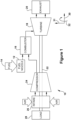
- FIG. 1 is a block diagram of a gas turbine system or engine (or "gas turbine") 10.
- gas turbine 10 may employ a shroud segment having cooling channels and seals, which reduce stress modes in such hot gas path components and improve the efficiency of the engine.
- Gas turbine 10 may use liquid or gas fuel, such as natural gas and/or a hydrogen rich synthetic gas.
- fuel nozzles 12 intake a fuel supply 14, mix the fuel with an oxidant, such as air, oxygen, oxygen-enriched air, oxygen reduced air, or any combination thereof. Once the fuel and air have been mixed, the fuel nozzles 12 distribute the fuel-air mixture into a combustor 16 in a suitable ratio for optimal combustion, emissions, fuel consumption, and power output.
- an oxidant such as air, oxygen, oxygen-enriched air, oxygen reduced air, or any combination thereof.
- Gas turbine 10 may include one or more fuel nozzles 12 located inside one or more combustors 16.
- the fuel-air mixture combusts in a chamber within combustor 16, thereby creating hot pressurized exhaust gases.
- Combustor 16 directs the exhaust gases (e.g., hot pressurized gas) through a transition piece into alternating rows of stationary stator blades and rotating rotor blades, which causes rotation of a turbine section or turbine 18 within a turbine casing.
- the exhaust gases expand through turbine 18 and flow toward an exhaust outlet 20.
- Shaft 22 may operably connected turbine 18 to a compressor 24.
- shaft 22 defines a center axis of gas turbine 10, i.e., turbine 18 and compressor 24. Relative to the center axis, an axial direction 30 is defined, which represents movement along the center axis, a radial direction 31 is defined, which represents movement toward or away from the center axis, and a circumferential direction 32 is defined, which represents movement around the center axis.
- Compressor 24 also includes blades coupled to shaft 22. As shaft 22 rotates, the blades within compressor 24 also rotate, thereby compressing air from an air intake 26 through compressor 24 and into fuel nozzles 12 and/or combustor 16. A portion of the compressed air (e.g., discharged air) from compressor 24 may be diverted to turbine 18 or its components without passing through combustor 16. The discharged air may be utilized as a coolant to cool turbine components, such as shrouds and nozzles on the stator, along with rotor blades, disks, and spacers on the rotor. Shaft 22 may also be connected to a load 28, which may be a vehicle or a stationary load, such as a propeller on an aircraft or an electrical generator in a power plant.
- a load 28 which may be a vehicle or a stationary load, such as a propeller on an aircraft or an electrical generator in a power plant.
- Hot gas path 38 may include a rotor blade 33 that is part of a row of rotor blades. The row of rotor blades may be disposed in serial flow relationship axially aft or downstream of a row of stationary turbine stator blades (not shown).
- Hot gas path 38 may also include a stationary shroud segment 34, which is circumferentially disposed about and radially outward (or "outboard") of rotor blade 33.
- shroud segment 34 may include an inner shroud segment 35 that resides radially inward (or "inboard”) of an outer shroud segment 36.
- a cavity 37 may be formed between inner and outer shroud segments 35, 36.
- cooling air is provided to cavity 37 through one or more coolant supply channels 39 formed through outer shroud segment 36. As will be seen, such cooling air may then be directed into internal cooling passages or channels formed through the interior of inner shroud segment 35.
- each shroud segment 34 may include one or more inner and outer shroud segments 35, 36. Multiple shroud segments 34 then may be circumferentially stacked to form a shroud ring disposed just outboard of the row of rotor blades, with each of the shroud segments 34 having one or more inner shroud segments 35 coupled to one or more outer shroud segments 36.
- inner shroud segments 35 may be circumferentially stacked such that a ring of inner shroud segments surrounds the row of rotor blades 33.
- inner shroud segment 35 and outer shroud segment 36 may have an arcuate shape or arcuately shaped surfaces.
- inner shroud segment 35 includes an upstream or leading edge 44 that opposes a downstream or trailing edge 46, which are so called given the flow direction of working fluid through the hot gas path. Extending between leading edge 44 and trailing edge 46, inner shroud segment 35 includes circumferentially oriented and opposing edges, which will be referred to herein as circumferential edges or, more specifically, first circumferential edge 48 and second circumferential edge 50. Inner shroud segment 35 also is generally formed by a pair of opposed lateral sides or faces 52, 54 that extend between leading and trailing edges 44, 46 and first and second circumferential edges 48, 50.
- lateral faces 52, 54 of inner shroud segment 35 may include an outboard face 52 and inboard face 54.
- outboard face 52 is directed toward outer shroud segment 36 (and cavity 37 that may be formed between inner shroud segment 35 and outer shroud segment 36), while inboard face 54 is directed toward hot gas path 38, where it defines an outer radial boundary thereof.
- Inboard face 54 of inner shroud segment 35 may be substantially planar except for a gradual curvature in between first and second circumferential edges 48, 50.
- inner shroud segment 35 may further be described relative to axial, radial and circumferential directions 30, 31, 32 of turbine 18.
- opposed leading and trailing edges 44, 46 are offset in the axial direction 30.
- the distance of this offset in the axial direction 30 is defined as the width dimension (or "width") of inner shroud segment 35.
- opposed first and second circumferential edges 48, 50 of inner shroud segment 35 are offset in the circumferential direction 32.
- the distance of this offset in the circumferential direction 32 is defined as the length dimension (or "length") of inner shroud segment 35.
- the opposed outboard and inboard faces 52, 54 of inner shroud segment 35 are offset in the radial direction 31.
- the distance of this offset in the radial direction 31 is defined as the height dimension (or "height") of inner shroud segment 35.
- Figure 3 is a cross-sectional side view of a sealing arrangement or seal 55 as may be formed between adjacent first and second inner shroud segments 35a, 35b. As shown, the two inner shroud segments 35a, 35b abut one another at an interface 56 (the proportions of which have been exaggerated for purposes of description). As will be appreciated, interface 56 is formed between first circumferential edge 48 of first inner shroud segment 35a and second circumferential edge 50 of second inner shroud segments 35b. As part of seal 55, each of first circumferential edge 48 and second circumferential edge 50 includes a slot 57 formed longitudinally to receive a corresponding sealing member 58.
- slot 57 may extend from leading edge 44 to trailing edge 46 of inner shroud segments 35a, 35b.
- sealing member 58 also may be configured to extend from leading edge 44 to trailing edge 46 of inner shroud segments 35a, 35b. It will be appreciated that once the adjacent inner shroud segments 35a, 35b are assembled to form interface 56, slots 57 cooperate or align to form a continuous seal chamber 59 that spans across interface 56.
- seal chamber 59 is configured to accept a correspondingly shaped sealing member 58 such that seal chamber 59 restricts movement of sealing member 58.
- seal chamber 59 maintains sealing member 58 in a proper sealing position, i.e., so that sealing member 58 spans across the gap formed at interface 56. Sealing member 58 thereby prevents or limits exhaust gases from leaking or escaping from hot gas path 18 via interface 56. Sealing member 58 separates cool fluid, such as air, proximate to outboard face 52 of inner shroud segment 35 from hot fluid, such as hot gases of hot gas path 18, proximate to inboard face 54.
- sealing member 58 degrades over time due to the extreme temperatures to which it is subjected given its position near hot gas path 18. Further, sealing member 58 is mechanically stressed by vibrations and/or relative movement between adjacent inner shroud segments 35. Over time, such degradation negatively impacts the performance of seal 55, allowing hot gas leakage that can damage components and negatively impact engine efficiency. While conventional seals in this region have been shown to perform adequately in certain ways, technical advances that extend component life of seal 55 or improve sealing performance could directly translate into improved efficiency and operational cost-effectiveness via reduced maintenance and downtime.
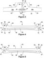
- FIGS 4 and 5 illustrate side cross-sectional views of an inner shroud segment 35 having a cooling channel 60 in accordance with the present disclosure.
- exemplary embodiments of the present invention disclose inner shroud segments 35 having one or more cooling channels 60 with their respective outlets 63 positioned to supply coolant directly to slots 57 and, thus, a seal 69 formed therein.
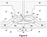
- Figure 6 illustrates a cross-sectional view of seal 69 according to embodiments of the present disclosure-exemplary embodiments will now be presented.
- components and elements that correspond to those already identified in preceding figures are identified with similar reference numerals, but only discussed in particular, as necessary, or desirable, to an understanding of the present embodiments.
- first inner shroud segment 35a and second inner shroud segment 35b As indicated, first and second inner shroud segments 35a, 35b abut one another along an interface 56 formed between first circumferential edge 48 of first inner shroud segment 35a and second circumferential edge 50 of second inner shroud segment 35b.
- first circumferential edge 48 and second circumferential edge 50 include cooperating slots 57 formed longitudinally to receive a sealing member 58.
- Slots 57 may extend between leading edge 44 a trailing edge 46 of first and second inner shroud segments 35a, 35b. Positioned within slots 57, sealing member 58 also may extend from leading edge 44 to trailing edge 46 of first and second inner shroud segments 35a, 35b. It will be appreciated that once first and second inner shroud segments 35a, 35b are positioned as shown, slots 57 cooperate to form a seal chamber 59 that positions and maintains sealing member 58 in a position that spans across interface 56 and thereby seals it.
- cooling channel 60 may broadly include any cooling passage configured for receiving and directing coolant through the interior of inner shroud segment 35.
- cooling channel 60 may be oriented in various directions and disposed within and through various regions of inner shroud segment 35, as may be necessary to satisfy component cooling requirements.
- cooling channel 60 may extend axially, circumferentially, and/or radially across the width, length, and/or height, respectively, of inner shroud segment 35.
- cooling channel 60 is oriented so that it extends lengthwise approximately in the circumferential direction 32 or along the length of inner shroud segment 35.
- cooling channel 60 may extend across a majority of the length of inner shroud segment 35, such as, across at least 50% of the length of inner shroud segment 35. According to alternative embodiments, cooling channel 60 may extend across at least 75% of the length of inner shroud segment 35.
- Cooling channels 60 of the present disclosure may generally extend lengthwise between an inlet 62 and outlet 63, both of which may be formed on an exterior surface of inner shroud segment 35. Between inlet 62 and outlet 63, cooling channel 60 may be more specifically described as extending lengthwise between non-overlapping and sequential sections, which, for the purposes herein, are designated: an upstream section 65; middle section 66; and downstream section 67. As shown in Figures 4 and 5 , middle section 66 may be the lengthiest section, which, according to exemplary embodiments, is substantially linear and disposed near and approximately parallel to inboard face 54. As will be appreciated, middle section of cooling channel 60 is configured in this way to provide cooling to inboard face 54.
- Upstream section 65 of cooling channel 60 is the section that supplies coolant to middle section 66, and, thus, upstream section 65 may extend generally between inlet 62 and middle section 66.
- Downstream section 67 of cooling channel 60 is the section through which coolant is expelled after usage, and, thus, downstream section 67 may extend between middle section 66 and outlet 63.
- inner shroud segments 35a, 35b may include a rail portion or rail 68 at circumferential edges 48, 50.
- rail 68 is a lengthwise section of increased height that is adjacent to circumferential edges 48, 50.
- inner shroud segment 35 may have rails 68.
- upstream section 65 is disposed in a rail 68 while its corresponding downstream section 67 is disposed in an opposing rail 68.
- upstream section 65 of cooling channel 60 may extend in an inboard direction between an inlet 62 formed on outboard face 52 and a connection made with middle section 66, where that connection is near inboard face 54.
- downstream section 67 may extend in an outboard direction from a connection made with middle section 66. As discussed more below, downstream section 67 then may extend in an inboard direction as it nears outlet 63.
- inlet 62 of cooling channel 60 may be formed on an exterior surface of inner shroud segment 35 and configured to receive a supply of coolant.
- the exterior surface on which inlet 62 of cooling channel 60 is disposed may be a surface defined within cavity 37. In this position, as will be appreciated, inlet 62 receives coolant that is delivered to cavity 37 via coolant supply channels 39.
- Other configurations are also possible.
- outlet 63 of cooling channel 60 may be disposed on either of first and second circumferential edges 48, 50 and, more particularly, on an exterior surface that defines slot 57.
- slot 57 is more particularly described according to the claimed invention as having been defined by several particular surfaces, which include an outboard surface or "ceiling” 73 (which defines a boundary of slot 57 in the outboard direction) and may include also an inboard surface or "floor” 75 (which defines a boundary of slot 57 in the inboard direction).
- outlet 63 is formed through ceiling 73 of slot 57.
- outboard ceiling 73 may include a beveled portion 83 adjacent to circumferential edges 48, 50.
- outlet (63) is formed through outboard ceiling 73 of slot 57.
- outlet 63 is oriented or aimed so that coolant released therefrom has an initial trajectory that includes an inboard directional component.
- the initial trajectory trains coolant released by outlet 63 upon sealing member 58.
- outlet 63 of cooling channel 60 may be configured as an impingement outlet or, as also used herein, have an impingement outlet configuration.
- an impingement outlet configuration is an outlet that impinges the flow of coolant being expelled through it via a reduction in cross-sectional flow area.
- the impingement outlet configuration is one in which the reference outlet has a cross-sectional flow area that is significantly reduced than the cross-sectional flow area of the reference cooling channel.
- the reference outlet may have a cross-sectional flow area that is less than 50% or 60% of the cross-sectional flow area of the reference cooling channel.
- the cross-sectional flow area of an impingement outlet 63 may be less than 60% of the cross-sectional flow area of cooling channel 60 that corresponds to it.
- the narrowing cross-sectional area of this type of outlet increases the velocity of the coolant being expelled from it, thereby increasing the coolant's heat transfer coefficient and cooling effectiveness within seal 69.
- the release of high velocity coolant in this manner-particularly where that release is aimed in the inboard direction- may enhance the effectiveness of seal 69.
- the released coolant may pressurize interface 56 and directionally opposes hot gases entering interface 56 from hot gas path 18.
- cooling channels 60 are provided within cooling configurations.
- the views of Figures 4 and 5 may be understood as cross-sections taken at different positions along the width of an inner shroud segment 35 that has multiple such cooling channels 60.
- some of those cooling channels 60 may be oriented to direct coolant to outlets 63 formed in slot 57 disposed on first circumferential edge 48, while others of those cooling channels 60 are oriented to direct coolant to outlets 63 formed in slot 57 disposed on second circumferential edge 50.
- a first example of cooling channel 60 extends lengthwise toward an outlet 63 formed within slot 57 disposed on second circumferential edge 50
- a second example of cooling channel 60 extends lengthwise toward an outlet 63 formed within slot 57 disposed on first circumferential edge 48.
- the present disclosure provides cooling configurations by which coolant that has already been circulated through interior regions of inner shroud segment 35 can be employed at release for the benefit of seals that are typically formed at circumferential edges of inner shroud segments.
- cooling configurations of the present disclosure may include multiple such cooling channels 60, such as, for example, 6, 10, 20 or more.
- the multiple cooling channels 60 may be arranged in a parallel configuration so that their respective outlets 63 are spaced along the length of slot 57 and, thereby, provide even cooling over the length of seal 69 and sealing member 58. Further, the multiple cooling channels 60 may be arranged according to an alternating counterflow arrangement in which adjacent cooling channels 60 have flow directions that are oppositely oriented, i.e., so that coolant flows in the opposite directions. In this way, the multiple impingement outlets 63 may be desirably spaced along the length of slots 57 formed on both circumferential edges 48, 50 of inner shroud segment 35.
- the disclosed cooling configurations and seals for hot gas path components have been found to cool using less coolant as well as improve sealing characteristics, respectively, compared with conventional cooling configurations and seals, resulting in reduced costs associated with cooling, greater engine efficiency, and lower maintenance costs.
- the internal cooling and sealing configurations of the present invention may be formed in hot gas path components, such as inner shroud segment 35, via any conventional manufacturing technique, including electrical discharge machining, drilling, casting, additive manufacturing, a combination thereof, or any other technique.
Landscapes
- Engineering & Computer Science (AREA)
- Mechanical Engineering (AREA)
- General Engineering & Computer Science (AREA)
- Physics & Mathematics (AREA)
- Fluid Mechanics (AREA)
- Turbine Rotor Nozzle Sealing (AREA)
Description
- The subject matter disclosed herein relates to hot gas path components within the turbine of a gas turbine engine, and, more specifically, but not by way of limitation, to the interior structure and cooling configuration of stationary shrouds formed about turbine rotor blades.
- Gas turbine engines include compressor and turbine sections in which rows of blades are axially stacked in stages. Each stage typically includes a row of circumferentially-spaced stator blades, which are fixed, and a row of rotor blades, which rotate about a central turbine axis or shaft. In operation, generally, the compressor rotor blades are rotated about the shaft, and, acting in concert with the stator blades, compress a flow of air. This supply of compressed air then is used within a combustor to combust a supply of fuel. The resulting flow of hot expanding combustion gases, which is often referred to as working fluid, is then expanded through the turbine section of the engine. Within the turbine, the working fluid is redirected by the stator blades onto the rotor blades so to power rotation. Stationary shrouds may be constructed about the rotor blades to define a boundary of the hot gas path. The rotor blades are connected to a central shaft such that the rotation of the rotor blades rotates the shaft, and, in this manner, the energy of the fuel is converted into the mechanical energy of the rotating shaft, which, for example, may be used to rotate the rotor blades of the compressor, so to produce the supply of compressed air needed for combustion, as well as, rotate the coils of a generator so to generate electrical power. During operation, because of the high temperatures, velocity of the working fluid, and rotational velocity of the engine, many of the components within the hot gas path become highly stressed by extreme mechanical and thermal loads.
- Many industrial applications, such as those involving power generation and aviation, still rely heavily on gas turbine engines, and because of this, the design of more efficient engines is an ongoing objective. Even incremental advances in machine performance, efficiency, or cost-effectiveness are meaningful in the competitive markets that have evolved around this technology. While there are several known strategies for improving the efficiency of gas turbines-for example, increasing the size of the engine, firing temperatures, or rotational velocities-each generally places additional strain on hot gas path components that are already highly stressed. As a result, there remains a general need for improved apparatus, methods or systems for alleviating such stresses or, alternatively, enhancing the durability of such components so they may better withstand them. For example, extreme temperature and pressure within the hot gas path stress stationary shrouds and seals formed between adjoining shroud segments, causing degradation and shortening the useful life of the component. Novel shroud designs are needed that optimize coolant and sealing efficiency, while also being cost-effective to construct, durable, and flexible in application.
-
EP 1 887 191 A2 shows a gas turbine engine having a shroud assembly. By means of a cooling passage, cooling air is provided towards the shroud. -
US 2001/0005555 A1 discloses a heat shield for gas turbines. -
US 2004/0047725 A1 relates to a ring segment arranged around rotating blades of a gas turbine. - A gas turbine engine having a seal arrangement arranged circumferentially around a working fluid path of a gas turbine engine is disclosed in
EP 0 694 677 A1 . - Shroud arrangements for gas turbines are also known from
US 5 609 469 A ,US 2015/007581 A1 andUS 2015/118022 A1 . - The present application describes an inner shroud segment for use in a stationary shroud ring encircling a hot gas path of a gas turbine engine according to claim 1 and a turbine of a gas turbine engine that includes inner shroud segments according to claim 11.
- These and other features of this disclosure will be more completely understood and appreciated by careful study of the following more detailed description of exemplary embodiments of the disclosure taken in conjunction with the accompanying drawings, in which:
-
Figure 1 is a block diagram of a gas turbine engine in which shrouds of the present disclosure may be used; -
Figure 2 is a side view of a hot gas path having a rotor blade and stationary shroud with which the seal of the present disclosure may be used; -
Figure 3 is side cross-sectional view of a conventional sealing arrangement between abutting inner shroud segments; -
Figure 4 is side cross-sectional view of an inner shroud segment that includes an interior cooling and sealing configuration in accordance with the present disclosure; -
Figure 5 is side cross-sectional view of an inner shroud segment that includes an interior cooling and sealing configuration in accordance with the present disclosure; and -
Figure 6 is an enhanced cross-sectional view of a seal between inner shroud segments having a cooling configuration and sealing arrangement in accordance with the present disclosure. - The present disclosure is directed to systems and methods for cooling and sealing components of a turbine, specifically, an inner shroud segment, disposed along a hot gas path. As will be seen, the inner shroud segment of the present invention includes an internal cooling configuration (or "cooling configuration") in which particular channels are formed within the interior of the inner shroud segment and a sealing arrangement.
- As used herein, "downstream" and "upstream" are terms that indicate a flow direction of a fluid through a channel or passage. Thus, for example, relative to the flow of working fluid through the turbine, the term "downstream" refers to a direction that generally corresponds to the direction of the flow, and the term "upstream" generally refers to the direction that is opposite of the direction of flow. The term "radial" refers to movement or position perpendicular to an axis or center line. It may be useful to describe parts that are at differing radial positions with regard to an axis. In this case, if a first component resides closer to the axis than a second component, it may be stated herein that the first component is "radially inward" of the second component. If, on the other hand, the first component resides further from the axis than the second component, it may be stated herein that the first component is "radially outward" or "outboard" of the second component. The term "axial" refers to movement or position parallel to an axis. Finally, the term "circumferential" refers to movement or position around an axis.
- Turning to the drawings,
Figure 1 is a block diagram of a gas turbine system or engine (or "gas turbine") 10. As described in detail below,gas turbine 10 may employ a shroud segment having cooling channels and seals, which reduce stress modes in such hot gas path components and improve the efficiency of the engine.Gas turbine 10 may use liquid or gas fuel, such as natural gas and/or a hydrogen rich synthetic gas. As depicted,fuel nozzles 12 intake afuel supply 14, mix the fuel with an oxidant, such as air, oxygen, oxygen-enriched air, oxygen reduced air, or any combination thereof. Once the fuel and air have been mixed, thefuel nozzles 12 distribute the fuel-air mixture into acombustor 16 in a suitable ratio for optimal combustion, emissions, fuel consumption, and power output. -
Gas turbine 10 may include one ormore fuel nozzles 12 located inside one ormore combustors 16. The fuel-air mixture combusts in a chamber withincombustor 16, thereby creating hot pressurized exhaust gases.Combustor 16 directs the exhaust gases (e.g., hot pressurized gas) through a transition piece into alternating rows of stationary stator blades and rotating rotor blades, which causes rotation of a turbine section orturbine 18 within a turbine casing. The exhaust gases expand throughturbine 18 and flow toward anexhaust outlet 20. As the exhaust gases pass throughturbine 18, the gases force the rotor blades to rotate ashaft 22. Shaft 22 may operably connectedturbine 18 to acompressor 24. As will be appreciated,shaft 22 defines a center axis ofgas turbine 10, i.e.,turbine 18 andcompressor 24. Relative to the center axis, anaxial direction 30 is defined, which represents movement along the center axis, aradial direction 31 is defined, which represents movement toward or away from the center axis, and acircumferential direction 32 is defined, which represents movement around the center axis. -
Compressor 24 also includes blades coupled toshaft 22. Asshaft 22 rotates, the blades withincompressor 24 also rotate, thereby compressing air from anair intake 26 throughcompressor 24 and intofuel nozzles 12 and/orcombustor 16. A portion of the compressed air (e.g., discharged air) fromcompressor 24 may be diverted toturbine 18 or its components without passing throughcombustor 16. The discharged air may be utilized as a coolant to cool turbine components, such as shrouds and nozzles on the stator, along with rotor blades, disks, and spacers on the rotor.Shaft 22 may also be connected to aload 28, which may be a vehicle or a stationary load, such as a propeller on an aircraft or an electrical generator in a power plant. -
Figure 2 shows an exemplary axial section of ahot gas path 38 as may be included within a turbine of a gas turbine. As shown,hot gas path 38 may include a rotor blade 33 that is part of a row of rotor blades. The row of rotor blades may be disposed in serial flow relationship axially aft or downstream of a row of stationary turbine stator blades (not shown).Hot gas path 38 may also include astationary shroud segment 34, which is circumferentially disposed about and radially outward (or "outboard") of rotor blade 33. As illustrated,shroud segment 34 may include aninner shroud segment 35 that resides radially inward (or "inboard") of anouter shroud segment 36. Acavity 37 may be formed between inner andouter shroud segments cavity 37 through one or morecoolant supply channels 39 formed throughouter shroud segment 36. As will be seen, such cooling air may then be directed into internal cooling passages or channels formed through the interior ofinner shroud segment 35. - As will be appreciated, each
shroud segment 34 may include one or more inner andouter shroud segments Multiple shroud segments 34 then may be circumferentially stacked to form a shroud ring disposed just outboard of the row of rotor blades, with each of theshroud segments 34 having one or moreinner shroud segments 35 coupled to one or moreouter shroud segments 36. Within this assembly,inner shroud segments 35 may be circumferentially stacked such that a ring of inner shroud segments surrounds the row of rotor blades 33. Given this arrangement,inner shroud segment 35 andouter shroud segment 36 may have an arcuate shape or arcuately shaped surfaces. - In accordance with its general configuration and orientation within
turbine 18, as used herein,inner shroud segment 35 includes an upstream or leadingedge 44 that opposes a downstream or trailingedge 46, which are so called given the flow direction of working fluid through the hot gas path. Extending between leadingedge 44 and trailingedge 46,inner shroud segment 35 includes circumferentially oriented and opposing edges, which will be referred to herein as circumferential edges or, more specifically, firstcircumferential edge 48 and secondcircumferential edge 50.Inner shroud segment 35 also is generally formed by a pair of opposed lateral sides or faces 52, 54 that extend between leading and trailingedges circumferential edges inner shroud segment 35 may include anoutboard face 52 andinboard face 54. As will be appreciated,outboard face 52 is directed toward outer shroud segment 36 (andcavity 37 that may be formed betweeninner shroud segment 35 and outer shroud segment 36), while inboardface 54 is directed towardhot gas path 38, where it defines an outer radial boundary thereof.Inboard face 54 ofinner shroud segment 35 may be substantially planar except for a gradual curvature in between first and secondcircumferential edges - Positioned as it is about the central axis of
turbine 18, the shape and dimensions ofinner shroud segment 35 may further be described relative to axial, radial andcircumferential directions turbine 18. Thus, opposed leading and trailingedges axial direction 30. As used herein, the distance of this offset in theaxial direction 30 is defined as the width dimension (or "width") ofinner shroud segment 35. Additionally, opposed first and secondcircumferential edges inner shroud segment 35 are offset in thecircumferential direction 32. As used herein, the distance of this offset in thecircumferential direction 32 is defined as the length dimension (or "length") ofinner shroud segment 35. Finally, the opposed outboard and inboard faces 52, 54 ofinner shroud segment 35 are offset in theradial direction 31. As used herein, the distance of this offset in theradial direction 31 is defined as the height dimension (or "height") ofinner shroud segment 35. -
Figure 3 is a cross-sectional side view of a sealing arrangement or seal 55 as may be formed between adjacent first and secondinner shroud segments inner shroud segments interface 56 is formed between firstcircumferential edge 48 of firstinner shroud segment 35a and secondcircumferential edge 50 of secondinner shroud segments 35b. As part ofseal 55, each of firstcircumferential edge 48 and secondcircumferential edge 50 includes aslot 57 formed longitudinally to receive a corresponding sealingmember 58. In each case, slot 57 may extend from leadingedge 44 to trailingedge 46 ofinner shroud segments slots 57, sealingmember 58 also may be configured to extend from leadingedge 44 to trailingedge 46 ofinner shroud segments inner shroud segments interface 56,slots 57 cooperate or align to form acontinuous seal chamber 59 that spans acrossinterface 56. As will be appreciated,seal chamber 59 is configured to accept a correspondingly shaped sealingmember 58 such thatseal chamber 59 restricts movement of sealingmember 58. In this way,seal chamber 59 maintains sealingmember 58 in a proper sealing position, i.e., so that sealingmember 58 spans across the gap formed atinterface 56. Sealingmember 58 thereby prevents or limits exhaust gases from leaking or escaping fromhot gas path 18 viainterface 56. Sealingmember 58 separates cool fluid, such as air, proximate tooutboard face 52 ofinner shroud segment 35 from hot fluid, such as hot gases ofhot gas path 18, proximate toinboard face 54. - As will be appreciated, however, sealing
member 58 degrades over time due to the extreme temperatures to which it is subjected given its position nearhot gas path 18. Further, sealingmember 58 is mechanically stressed by vibrations and/or relative movement between adjacentinner shroud segments 35. Over time, such degradation negatively impacts the performance ofseal 55, allowing hot gas leakage that can damage components and negatively impact engine efficiency. While conventional seals in this region have been shown to perform adequately in certain ways, technical advances that extend component life ofseal 55 or improve sealing performance could directly translate into improved efficiency and operational cost-effectiveness via reduced maintenance and downtime. - Turning now to the present invention,
Figures 4 and 5 illustrate side cross-sectional views of aninner shroud segment 35 having a coolingchannel 60 in accordance with the present disclosure. As will be seen, to reduce seal degradation and/or improve sealing performance, exemplary embodiments of the present invention discloseinner shroud segments 35 having one ormore cooling channels 60 with theirrespective outlets 63 positioned to supply coolant directly toslots 57 and, thus, aseal 69 formed therein. With reference also toFigure 6 -which illustrates a cross-sectional view ofseal 69 according to embodiments of the present disclosure-exemplary embodiments will now be presented. For convenience, components and elements that correspond to those already identified in preceding figures are identified with similar reference numerals, but only discussed in particular, as necessary, or desirable, to an understanding of the present embodiments. - In regard to seal 69, as shown in
Figure 6 , it may be formed between circumferential edges of adjacentinner shroud segments 35 in much the same way as described above forseal 55. For description purposes, the adjacent inner shrouds segments have been designated as a firstinner shroud segment 35a and secondinner shroud segment 35b. As indicated, first and secondinner shroud segments interface 56 formed between firstcircumferential edge 48 of firstinner shroud segment 35a and secondcircumferential edge 50 of secondinner shroud segment 35b. As part ofseal 69, firstcircumferential edge 48 and secondcircumferential edge 50 include cooperatingslots 57 formed longitudinally to receive a sealingmember 58.Slots 57 may extend between leading edge 44 a trailingedge 46 of first and secondinner shroud segments slots 57, sealingmember 58 also may extend from leadingedge 44 to trailingedge 46 of first and secondinner shroud segments inner shroud segments slots 57 cooperate to form aseal chamber 59 that positions and maintains sealingmember 58 in a position that spans acrossinterface 56 and thereby seals it. - In regard to cooling
channel 60, unless otherwise limited, it may broadly include any cooling passage configured for receiving and directing coolant through the interior ofinner shroud segment 35. Thus, according to exemplary embodiments, coolingchannel 60 may be oriented in various directions and disposed within and through various regions ofinner shroud segment 35, as may be necessary to satisfy component cooling requirements. For example, coolingchannel 60 may extend axially, circumferentially, and/or radially across the width, length, and/or height, respectively, ofinner shroud segment 35. According to certain preferred embodiments, coolingchannel 60 is oriented so that it extends lengthwise approximately in thecircumferential direction 32 or along the length ofinner shroud segment 35. In certain embodiments, coolingchannel 60 may extend across a majority of the length ofinner shroud segment 35, such as, across at least 50% of the length ofinner shroud segment 35. According to alternative embodiments, coolingchannel 60 may extend across at least 75% of the length ofinner shroud segment 35. -
Cooling channels 60 of the present disclosure may generally extend lengthwise between aninlet 62 andoutlet 63, both of which may be formed on an exterior surface ofinner shroud segment 35. Betweeninlet 62 andoutlet 63, coolingchannel 60 may be more specifically described as extending lengthwise between non-overlapping and sequential sections, which, for the purposes herein, are designated: anupstream section 65;middle section 66; anddownstream section 67. As shown inFigures 4 and 5 ,middle section 66 may be the lengthiest section, which, according to exemplary embodiments, is substantially linear and disposed near and approximately parallel toinboard face 54. As will be appreciated, middle section of coolingchannel 60 is configured in this way to provide cooling toinboard face 54.Upstream section 65 of coolingchannel 60 is the section that supplies coolant tomiddle section 66, and, thus,upstream section 65 may extend generally betweeninlet 62 andmiddle section 66.Downstream section 67 of coolingchannel 60 is the section through which coolant is expelled after usage, and, thus,downstream section 67 may extend betweenmiddle section 66 andoutlet 63. - As shown most clearly in
Figures 4 and 5 ,inner shroud segments rail 68 atcircumferential edges rail 68 is a lengthwise section of increased height that is adjacent tocircumferential edges circumferential edges inner shroud segment 35 may have rails 68. As depicted inFigures 4 through 6 , in accordance with certain preferred embodiments,upstream section 65 is disposed in arail 68 while its correspondingdownstream section 67 is disposed in an opposingrail 68. For example, withinrail 68,upstream section 65 of coolingchannel 60 may extend in an inboard direction between aninlet 62 formed onoutboard face 52 and a connection made withmiddle section 66, where that connection is nearinboard face 54. Within opposingrail 68,downstream section 67 may extend in an outboard direction from a connection made withmiddle section 66. As discussed more below,downstream section 67 then may extend in an inboard direction as it nearsoutlet 63. - In regard to
inlet 62 of coolingchannel 60, according to exemplary embodiments, it may be formed on an exterior surface ofinner shroud segment 35 and configured to receive a supply of coolant. For example, the exterior surface on whichinlet 62 of coolingchannel 60 is disposed may be a surface defined withincavity 37. In this position, as will be appreciated,inlet 62 receives coolant that is delivered tocavity 37 viacoolant supply channels 39. Other configurations are also possible. - In regard to
outlet 63 of coolingchannel 60, according to the present disclosure, it may be disposed on either of first and secondcircumferential edges slot 57. As used herein,slot 57 is more particularly described according to the claimed invention as having been defined by several particular surfaces, which include an outboard surface or "ceiling" 73 (which defines a boundary ofslot 57 in the outboard direction) and may include also an inboard surface or "floor" 75 (which defines a boundary ofslot 57 in the inboard direction). According to the claimed invention and as shown in the figures,outlet 63 is formed throughceiling 73 ofslot 57. As illustrated most clearly inFigure 6 ,outboard ceiling 73 may include abeveled portion 83 adjacent tocircumferential edges outboard ceiling 73 ofslot 57. Further, according to preferred embodiments,outlet 63 is oriented or aimed so that coolant released therefrom has an initial trajectory that includes an inboard directional component. Preferably, the initial trajectory trains coolant released byoutlet 63 upon sealingmember 58. - As also shown, according to certain preferred embodiments,
outlet 63 of coolingchannel 60 may be configured as an impingement outlet or, as also used herein, have an impingement outlet configuration. In general, an impingement outlet configuration is an outlet that impinges the flow of coolant being expelled through it via a reduction in cross-sectional flow area. For example, defined relative to a reference cooling channel having a reference outlet, the impingement outlet configuration is one in which the reference outlet has a cross-sectional flow area that is significantly reduced than the cross-sectional flow area of the reference cooling channel. Thus, as an example, the reference outlet may have a cross-sectional flow area that is less than 50% or 60% of the cross-sectional flow area of the reference cooling channel. For example, according to preferred embodiments, the cross-sectional flow area of animpingement outlet 63 may be less than 60% of the cross-sectional flow area of coolingchannel 60 that corresponds to it. As will be appreciated, the narrowing cross-sectional area of this type of outlet increases the velocity of the coolant being expelled from it, thereby increasing the coolant's heat transfer coefficient and cooling effectiveness withinseal 69. Additionally, the release of high velocity coolant in this manner-particularly where that release is aimed in the inboard direction-may enhance the effectiveness ofseal 69. Specifically, the released coolant may pressurizeinterface 56 and directionally opposes hotgases entering interface 56 fromhot gas path 18. - Though usage of a single
such cooling channel 60 is possible, in accordance with preferred embodiments,multiple cooling channels 60 are provided within cooling configurations. For example, the views ofFigures 4 and 5 may be understood as cross-sections taken at different positions along the width of aninner shroud segment 35 that has multiplesuch cooling channels 60. As illustrated by the two opposite flow directions ofFigures 4 and 5 , some of those coolingchannels 60 may be oriented to direct coolant tooutlets 63 formed inslot 57 disposed on firstcircumferential edge 48, while others of those coolingchannels 60 are oriented to direct coolant tooutlets 63 formed inslot 57 disposed on secondcircumferential edge 50. Thus, as shown inFigure 4 , a first example of coolingchannel 60 extends lengthwise toward anoutlet 63 formed withinslot 57 disposed on secondcircumferential edge 50, while, as shown inFigure 5 , a second example of coolingchannel 60 extends lengthwise toward anoutlet 63 formed withinslot 57 disposed on firstcircumferential edge 48. In this way, the present disclosure provides cooling configurations by which coolant that has already been circulated through interior regions ofinner shroud segment 35 can be employed at release for the benefit of seals that are typically formed at circumferential edges of inner shroud segments. Thus, it should be understood that cooling configurations of the present disclosure may include multiplesuch cooling channels 60, such as, for example, 6, 10, 20 or more. According to certain preferred embodiment, themultiple cooling channels 60 may be arranged in a parallel configuration so that theirrespective outlets 63 are spaced along the length ofslot 57 and, thereby, provide even cooling over the length ofseal 69 and sealingmember 58. Further, themultiple cooling channels 60 may be arranged according to an alternating counterflow arrangement in whichadjacent cooling channels 60 have flow directions that are oppositely oriented, i.e., so that coolant flows in the opposite directions. In this way, themultiple impingement outlets 63 may be desirably spaced along the length ofslots 57 formed on bothcircumferential edges inner shroud segment 35. - The disclosed cooling configurations and seals for hot gas path components, e.g.,
inner shroud segment 35, have been found to cool using less coolant as well as improve sealing characteristics, respectively, compared with conventional cooling configurations and seals, resulting in reduced costs associated with cooling, greater engine efficiency, and lower maintenance costs. As will be appreciated, the internal cooling and sealing configurations of the present invention may be formed in hot gas path components, such asinner shroud segment 35, via any conventional manufacturing technique, including electrical discharge machining, drilling, casting, additive manufacturing, a combination thereof, or any other technique. - As one of ordinary skill in the art will appreciate, the many varying features and configurations described above in relation to the several exemplary embodiments may be further selectively applied to form the other possible embodiments of the present disclosure. In addition, from the above description of several exemplary embodiments, those skilled in the art will perceive improvements, changes and modifications. Further, it should be apparent that the foregoing relates only to the described embodiments of the present application and that numerous changes and modifications may be made herein without departing from the claimed invention .
Claims (13)
- An inner shroud segment (35) for use in a stationary shroud ring encircling a hot gas path (38) of a gas turbine engine (10), the inner shroud segment (35) comprising:a cooling configuration that includes cooling channels (60) configured to receive and direct a coolant through an interior of the inner shroud segment (35), each of the cooling channels (60) extending lengthwise between a first end and a second end that comprises an outlet (63) formed through an exterior surface of the inner shroud segment (35);opposed first and second circumferential edges (48, 50); andfirst and second slots (57) formed in the first and second circumferential edges (48, 50), respectively, for receiving a sealing member (58);wherein:first and second slots (57) include an outboard ceiling (73) positioned radially outward from the sealing member (58); the inner shroud segment being characterized in thatthe outlet (63) of at least one of the cooling channels (60) is positioned within the outboard ceiling (73) of the first slot (57); andthe outlet (63) of at least one of the cooling channels (60) is positioned within the outboard ceiling (73) of the second slot (57).
- The inner shroud segment (35) according to claim 1, wherein a first cooling channel group comprises a plurality of the cooling channels (60), and a second cooling channel group comprises a plurality of the cooling channels (60);
wherein:each of the outlets (63) of the cooling channels (60) within the first cooling channel group comprises a position within the first slot (57); andeach of the outlets (63) of the cooling channels (60) within the second cooling channel group comprises a position within the second slot (57). - The inner shroud segment (35) according to claim 1 or 2, wherein the inner shroud segment (35) comprises:opposed leading and trailing edges (44, 46) extending between the first and second circumferential edges (48, 50); andopposed inner and outboard faces (54, 52) extending between the leading and trailing edges (44, 46) and the first and second circumferential edges (48, 50);wherein:an offset between the first and second circumferential edges (48, 50) defines a length of the inner shroud segment (35);an offset between the leading and trailing edges (44, 46) defines a width of the inner shroud segment (35); andan offset between the inner and outboard faces (54, 52) defines a height of the inner shroud segment (35);wherein each of the cooling channels (60) of the first and second cooling channel groups extends across at least 50% of the length of the inner shroud segment (35).
- The inner shroud segment (35) according to claim 3, wherein each of the cooling channels (60) of the first channel group and the second channel group extends across at least 75% of the length of the inner shroud segment (35).
- The inner shroud segment (35) of claim 3, wherein the cooling channels (60) comprise at least six of the cooling channels (60); wherein the outlets (63) of each of the cooling channels (60) are aimed such that an initial trajectory of coolant being released therefrom comprises a directional component in an inboard direction; and wherein the outlets (63) of the cooling channels (60) are spaced between the leading and trailing edges (44, 46) of the inner shroud segment (35).
- The inner shroud segment (35) according to claim 3, wherein the first slot (57) on the first circumferential edge (48) extends lengthwise between the leading and trailing edges (44, 46) of the inner shroud segment (35);wherein the second slot (57) on the second circumferential edge (50) extends lengthwise between the leading and trailing edges (44, 46) of the inner shroud segment (35); andwherein:the outlets (63) within the first slot (57) are spaced between the leading and trailing edges (44, 46) of the inner shroud segment (35); andthe outlets (63) within the second slot (57) are spaced between the leading and trailing edges (44, 46) of the inner shroud segment (35).
- The inner shroud segment (35) according to claim 3, wherein each of the first and second slots (57) is defined between a ceiling (73) and, opposed to the ceiling (73), a floor (75), wherein the ceiling (73) and the floor (75) are approximately parallel to the inner and outboard faces (54, 52), respectively;
wherein:each of the outlets (63) of the cooling channels (60) within the first cooling channel group is formed through the ceiling (73) of the first slot (57); andeach of the outlets (63) of the cooling channels (60) within the second cooling channel group is formed through the ceiling (73) of the second slot (57). - The inner shroud segment (35) according to claim 7, wherein the ceiling (73) of the first slot (57) comprises a beveled portion (83) adjacent to the first and second circumferential edges (48, 50); and wherein each of the outlets (63) of the cooling channels (60) within the first cooling channel group are formed through the beveled portion (83) of the ceiling (73) of the slot (57).
- The inner shroud segment (35) according to claim 4 and any of claims 3, 5 or 8, wherein the first end of each of the cooling channels (60) comprises an inlet (62) formed through the outboard face (52) of the inner shroud segment (35).
- The inner shroud segment (35) according to any of claims 3-8, wherein each of the outlets (63) of the cooling channels (60) within the first and second cooling channel groups comprises an impingement outlet configuration;
wherein the cooling channels (60) of the first and second cooling channel groups are:approximately parallel to each other; andarranged according to an alternating counterflow arrangement in which adjacent ones of the cooling channels (60) have oppositely oriented flow directions. - A turbine (18) of a gas turbine engine (10), the turbine (18) comprising adjacent inner shroud segments (35) according to any of the previous claims, that together form a portion of a stationary shroud ring encircling a hot gas path (38), wherein an interface (56) is formed between abutting first and second circumferential edges (48, 50) of a first inner shroud segment (35) and a second inner shroud segment (35), respectively, the interface (56) comprising:
a sealing member (58) positioned within a seal chamber (59) formed by the first and second slots (57) disposed on the first and second circumferential edges (48, 50) of the first and second inner shroud segments (35), the sealing member (58) correspondingly shaped with the seal chamber (59) such that operable engagement therewithin maintains the sealing member (58) positioned across the interface (56). - The turbine (18) according to claim 11, wherein the outlets (63) of each of the cooling channels (60) within the first and second cooling channel groups are aimed so that an initial trajectory of coolant released therefrom comprises a directional component in the inboard direction.
- The turbine (18) according to claim 11 or 12, wherein the sealing member (58) comprises opposed inner and outboard faces, where the outboard face of the sealing member faces the outboard direction;wherein the outlets (63) of each of the cooling channels (60) are aimed at the outboard face of the sealing member (58); andwherein each of the outlets (63) of the cooling channels (60) comprises an impingement outlet configuration.
Applications Claiming Priority (2)
| Application Number | Priority Date | Filing Date | Title |
|---|---|---|---|
| US15/995,082 US10815807B2 (en) | 2018-05-31 | 2018-05-31 | Shroud and seal for gas turbine engine |
| PCT/US2019/033882 WO2019231838A1 (en) | 2018-05-31 | 2019-05-24 | Shroud and seal for gas turbine engine |
Publications (2)
| Publication Number | Publication Date |
|---|---|
| EP3803060A1 EP3803060A1 (en) | 2021-04-14 |
| EP3803060B1 true EP3803060B1 (en) | 2024-08-28 |
Family
ID=66821505
Family Applications (1)
| Application Number | Title | Priority Date | Filing Date |
|---|---|---|---|
| EP19730080.9A Active EP3803060B1 (en) | 2018-05-31 | 2019-05-24 | Shroud and seal for gas turbine engine |
Country Status (4)
| Country | Link |
|---|---|
| US (1) | US10815807B2 (en) |
| EP (1) | EP3803060B1 (en) |
| JP (1) | JP7423548B2 (en) |
| WO (1) | WO2019231838A1 (en) |
Families Citing this family (18)
| Publication number | Priority date | Publication date | Assignee | Title |
|---|---|---|---|---|
| JP7530307B2 (en) * | 2021-01-22 | 2024-08-07 | 三菱重工業株式会社 | Flow passage plate, blade and gas turbine equipped with same, and method for manufacturing flow passage plate |
| CN114087072B (en) * | 2021-10-15 | 2022-11-22 | 中国联合重型燃气轮机技术有限公司 | Gas turbine and gas turbine with same |
| US12158072B1 (en) | 2023-12-04 | 2024-12-03 | Rolls-Royce Corporation | Turbine shroud segments with damping strip seals |
| US12188365B1 (en) | 2023-12-04 | 2025-01-07 | Rolls-Royce Corporation | Method and apparatus for ceramic matrix composite turbine shroud assembly |
| US12241376B1 (en) | 2023-12-04 | 2025-03-04 | Rolls-Royce Corporation | Locating plate for use with turbine shroud assemblies |
| US12152499B1 (en) | 2023-12-04 | 2024-11-26 | Rolls-Royce Corporation | Turbine shroud segments with strip seal assemblies having dampened ends |
| US12421862B2 (en) | 2023-12-04 | 2025-09-23 | Rolls-Royce Corporation | Turbine shroud assembly with angled cooling holes |
| US12286906B1 (en) | 2023-12-04 | 2025-04-29 | Rolls-Royce Corporation | Locating plate for use with turbine shroud assemblies |
| US12286885B1 (en) | 2023-12-04 | 2025-04-29 | Rolls-Royce Corporation | Turbine assembly with confronting vane and turbine shroud segment |
| US12421870B1 (en) | 2024-04-30 | 2025-09-23 | Rolls-Royce Corporation | Pin mounted ceramic matrix composite heat shields with impingement cooling |
| US12305525B1 (en) | 2024-05-30 | 2025-05-20 | Rolls-Royce Corporation | Turbine shroud assemblies with rod seal and strip seals |
| US12258880B1 (en) | 2024-05-30 | 2025-03-25 | Rolls-Royce Corporation | Turbine shroud assemblies with inter-segment strip seal |
| US12215593B1 (en) | 2024-05-30 | 2025-02-04 | Rolls-Royce Corporation | Turbine shroud assembly with inter-segment damping |
| US12416241B1 (en) | 2024-05-30 | 2025-09-16 | Rolls-Royce Corporation | Turbine shroud assemblies with strip seals |
| US12577881B2 (en) | 2024-05-31 | 2026-03-17 | Rolls-Royce Corporation | Turbine shroud assemblies with anti-migration seals |
| US12410725B1 (en) | 2024-05-31 | 2025-09-09 | Rolls-Royce Corporation | Turbine shroud assemblies with air activated pistons for biasing buffer cavity seals |
| US12352176B1 (en) | 2024-05-31 | 2025-07-08 | Rolls-Royce Corporation | Turbine shroud assemblies with channels for buffer cavity seal thermal management |
| US12228044B1 (en) | 2024-06-26 | 2025-02-18 | Rolls-Royce Corporation | Turbine shroud system with ceramic matrix composite segments and dual inter-segment seals |
Citations (1)
| Publication number | Priority date | Publication date | Assignee | Title |
|---|---|---|---|---|
| US20150118022A1 (en) * | 2013-10-28 | 2015-04-30 | General Electric Company | Re-use of internal cooling by medium in turbine hot gas path components |
Family Cites Families (23)
| Publication number | Priority date | Publication date | Assignee | Title |
|---|---|---|---|---|
| US5088888A (en) * | 1990-12-03 | 1992-02-18 | General Electric Company | Shroud seal |
| US5374161A (en) * | 1993-12-13 | 1994-12-20 | United Technologies Corporation | Blade outer air seal cooling enhanced with inter-segment film slot |
| EP0694677B1 (en) * | 1994-07-29 | 1999-04-21 | United Technologies Corporation | Seal for a gas turbine engine |
| US5609469A (en) | 1995-11-22 | 1997-03-11 | United Technologies Corporation | Rotor assembly shroud |
| JP3999395B2 (en) * | 1999-03-03 | 2007-10-31 | 三菱重工業株式会社 | Gas turbine split ring |
| DE19963371A1 (en) | 1999-12-28 | 2001-07-12 | Alstom Power Schweiz Ag Baden | Chilled heat shield |
| US6340285B1 (en) * | 2000-06-08 | 2002-01-22 | General Electric Company | End rail cooling for combined high and low pressure turbine shroud |
| JP2002201913A (en) * | 2001-01-09 | 2002-07-19 | Mitsubishi Heavy Ind Ltd | Split wall of gas turbine and shroud |
| JP4508482B2 (en) * | 2001-07-11 | 2010-07-21 | 三菱重工業株式会社 | Gas turbine stationary blade |
| US7033138B2 (en) * | 2002-09-06 | 2006-04-25 | Mitsubishi Heavy Industries, Ltd. | Ring segment of gas turbine |
| DE102004037356B4 (en) * | 2004-07-30 | 2017-11-23 | Ansaldo Energia Ip Uk Limited | Wall structure for limiting a hot gas path |
| GB0515868D0 (en) * | 2005-08-02 | 2005-09-07 | Rolls Royce Plc | Cooling arrangement |
| US7607885B2 (en) | 2006-07-31 | 2009-10-27 | General Electric Company | Methods and apparatus for operating gas turbine engines |
| US8079803B2 (en) * | 2008-06-30 | 2011-12-20 | Mitsubishi Heavy Industries, Ltd. | Gas turbine and cooling air supply structure thereof |
| US8585354B1 (en) * | 2010-01-19 | 2013-11-19 | Florida Turbine Technologies, Inc. | Turbine ring segment with riffle seal |
| US20120177479A1 (en) * | 2011-01-06 | 2012-07-12 | Gm Salam Azad | Inner shroud cooling arrangement in a gas turbine engine |
| US9151179B2 (en) * | 2011-04-13 | 2015-10-06 | General Electric Company | Turbine shroud segment cooling system and method |
| US8905708B2 (en) * | 2012-01-10 | 2014-12-09 | General Electric Company | Turbine assembly and method for controlling a temperature of an assembly |
| US9464538B2 (en) * | 2013-07-08 | 2016-10-11 | General Electric Company | Shroud block segment for a gas turbine |
| US9518478B2 (en) * | 2013-10-28 | 2016-12-13 | General Electric Company | Microchannel exhaust for cooling and/or purging gas turbine segment gaps |
| US9464530B2 (en) * | 2014-02-20 | 2016-10-11 | General Electric Company | Turbine bucket and method for balancing a tip shroud of a turbine bucket |
| WO2016152573A1 (en) * | 2015-03-26 | 2016-09-29 | 三菱日立パワーシステムズ株式会社 | Blade and gas turbine equipped with same |
| EP3141698A1 (en) * | 2015-09-10 | 2017-03-15 | Siemens Aktiengesellschaft | Arrangement for a gas turbine |
-
2018
- 2018-05-31 US US15/995,082 patent/US10815807B2/en active Active
-
2019
- 2019-05-24 WO PCT/US2019/033882 patent/WO2019231838A1/en not_active Ceased
- 2019-05-24 JP JP2020563436A patent/JP7423548B2/en active Active
- 2019-05-24 EP EP19730080.9A patent/EP3803060B1/en active Active
Patent Citations (1)
| Publication number | Priority date | Publication date | Assignee | Title |
|---|---|---|---|---|
| US20150118022A1 (en) * | 2013-10-28 | 2015-04-30 | General Electric Company | Re-use of internal cooling by medium in turbine hot gas path components |
Also Published As
| Publication number | Publication date |
|---|---|
| US10815807B2 (en) | 2020-10-27 |
| US20190368364A1 (en) | 2019-12-05 |
| WO2019231838A1 (en) | 2019-12-05 |
| EP3803060A1 (en) | 2021-04-14 |
| JP7423548B2 (en) | 2024-01-29 |
| JP2021525329A (en) | 2021-09-24 |
Similar Documents
| Publication | Publication Date | Title |
|---|---|---|
| US10815807B2 (en) | Shroud and seal for gas turbine engine | |
| US8075256B2 (en) | Ingestion resistant seal assembly | |
| US5466123A (en) | Gas turbine engine turbine | |
| US8636463B2 (en) | Interior cooling channels | |
| EP3168420A1 (en) | Shrouded turbine blade | |
| EP3803059B1 (en) | Shroud for gas turbine engine | |
| US9664058B2 (en) | Flowpath boundary and rotor assemblies in gas turbines | |
| CN110325712A (en) | The spline of turbogenerator | |
| US9777586B2 (en) | Flowpath boundary and rotor assemblies in gas turbines | |
| EP3329100B1 (en) | Cooling arrangements in tip shrouded turbine rotor blades | |
| US20170175557A1 (en) | Gas turbine sealing | |
| EP3181825B1 (en) | Shroud segment with hook-shaped cooling channels | |
| EP3803058B1 (en) | Shroud for gas turbine engine | |
| US10247013B2 (en) | Interior cooling configurations in turbine rotor blades | |
| US20170260873A1 (en) | System and method for cooling trailing edge and/or leading edge of hot gas flow path component | |
| US10550710B2 (en) | Shroud for gas turbine engine | |
| US20160123169A1 (en) | Methods and system for fluidic sealing in gas turbine engines | |
| US20160186592A1 (en) | Flowpath boundary and rotor assemblies in gas turbines | |
| US11415010B1 (en) | Turbine nozzle and gas turbine including the same | |
| US9771817B2 (en) | Methods and system for fluidic sealing in gas turbine engines | |
| AU2023212969B2 (en) | Gas turbine nozzles with cooling holes and turbine | |
| CN120608740A (en) | Turbine engine with a blade assembly having a set of cooling ducts |
Legal Events
| Date | Code | Title | Description |
|---|---|---|---|
| STAA | Information on the status of an ep patent application or granted ep patent |
Free format text: STATUS: UNKNOWN |
|
| STAA | Information on the status of an ep patent application or granted ep patent |
Free format text: STATUS: THE INTERNATIONAL PUBLICATION HAS BEEN MADE |
|
| PUAI | Public reference made under article 153(3) epc to a published international application that has entered the european phase |
Free format text: ORIGINAL CODE: 0009012 |
|
| STAA | Information on the status of an ep patent application or granted ep patent |
Free format text: STATUS: REQUEST FOR EXAMINATION WAS MADE |
|
| 17P | Request for examination filed |
Effective date: 20201119 |
|
| AK | Designated contracting states |
Kind code of ref document: A1 Designated state(s): AL AT BE BG CH CY CZ DE DK EE ES FI FR GB GR HR HU IE IS IT LI LT LU LV MC MK MT NL NO PL PT RO RS SE SI SK SM TR |
|
| AX | Request for extension of the european patent |
Extension state: BA ME |
|
| DAV | Request for validation of the european patent (deleted) | ||
| DAX | Request for extension of the european patent (deleted) | ||
| STAA | Information on the status of an ep patent application or granted ep patent |
Free format text: STATUS: EXAMINATION IS IN PROGRESS |
|
| 17Q | First examination report despatched |
Effective date: 20221213 |
|
| RAP1 | Party data changed (applicant data changed or rights of an application transferred) |
Owner name: GENERAL ELECTRIC TECHNOLOGY GMBH |
|
| GRAP | Despatch of communication of intention to grant a patent |
Free format text: ORIGINAL CODE: EPIDOSNIGR1 |
|
| STAA | Information on the status of an ep patent application or granted ep patent |
Free format text: STATUS: GRANT OF PATENT IS INTENDED |
|
| INTG | Intention to grant announced |
Effective date: 20240531 |
|
| GRAS | Grant fee paid |
Free format text: ORIGINAL CODE: EPIDOSNIGR3 |
|
| GRAA | (expected) grant |
Free format text: ORIGINAL CODE: 0009210 |
|
| STAA | Information on the status of an ep patent application or granted ep patent |
Free format text: STATUS: THE PATENT HAS BEEN GRANTED |
|
| AK | Designated contracting states |
Kind code of ref document: B1 Designated state(s): AL AT BE BG CH CY CZ DE DK EE ES FI FR GB GR HR HU IE IS IT LI LT LU LV MC MK MT NL NO PL PT RO RS SE SI SK SM TR |
|
| REG | Reference to a national code |
Ref country code: GB Ref legal event code: FG4D |
|
| REG | Reference to a national code |
Ref country code: CH Ref legal event code: EP |
|
| REG | Reference to a national code |
Ref country code: DE Ref legal event code: R096 Ref document number: 602019057862 Country of ref document: DE |
|
| REG | Reference to a national code |
Ref country code: NL Ref legal event code: FP |
|
| REG | Reference to a national code |
Ref country code: IE Ref legal event code: FG4D |
|
| REG | Reference to a national code |
Ref country code: LT Ref legal event code: MG9D |
|
| PG25 | Lapsed in a contracting state [announced via postgrant information from national office to epo] |
Ref country code: NO Free format text: LAPSE BECAUSE OF FAILURE TO SUBMIT A TRANSLATION OF THE DESCRIPTION OR TO PAY THE FEE WITHIN THE PRESCRIBED TIME-LIMIT Effective date: 20241128 |
|
| REG | Reference to a national code |
Ref country code: AT Ref legal event code: MK05 Ref document number: 1718134 Country of ref document: AT Kind code of ref document: T Effective date: 20240828 |
|
| PG25 | Lapsed in a contracting state [announced via postgrant information from national office to epo] |
Ref country code: PT Free format text: LAPSE BECAUSE OF FAILURE TO SUBMIT A TRANSLATION OF THE DESCRIPTION OR TO PAY THE FEE WITHIN THE PRESCRIBED TIME-LIMIT Effective date: 20241230 Ref country code: FI Free format text: LAPSE BECAUSE OF FAILURE TO SUBMIT A TRANSLATION OF THE DESCRIPTION OR TO PAY THE FEE WITHIN THE PRESCRIBED TIME-LIMIT Effective date: 20240828 Ref country code: GR Free format text: LAPSE BECAUSE OF FAILURE TO SUBMIT A TRANSLATION OF THE DESCRIPTION OR TO PAY THE FEE WITHIN THE PRESCRIBED TIME-LIMIT Effective date: 20241129 Ref country code: PL Free format text: LAPSE BECAUSE OF FAILURE TO SUBMIT A TRANSLATION OF THE DESCRIPTION OR TO PAY THE FEE WITHIN THE PRESCRIBED TIME-LIMIT Effective date: 20240828 |
|
| PG25 | Lapsed in a contracting state [announced via postgrant information from national office to epo] |
Ref country code: BG Free format text: LAPSE BECAUSE OF FAILURE TO SUBMIT A TRANSLATION OF THE DESCRIPTION OR TO PAY THE FEE WITHIN THE PRESCRIBED TIME-LIMIT Effective date: 20240828 |
|
| PG25 | Lapsed in a contracting state [announced via postgrant information from national office to epo] |
Ref country code: LV Free format text: LAPSE BECAUSE OF FAILURE TO SUBMIT A TRANSLATION OF THE DESCRIPTION OR TO PAY THE FEE WITHIN THE PRESCRIBED TIME-LIMIT Effective date: 20240828 |
|
| PG25 | Lapsed in a contracting state [announced via postgrant information from national office to epo] |
Ref country code: AT Free format text: LAPSE BECAUSE OF FAILURE TO SUBMIT A TRANSLATION OF THE DESCRIPTION OR TO PAY THE FEE WITHIN THE PRESCRIBED TIME-LIMIT Effective date: 20240828 Ref country code: IS Free format text: LAPSE BECAUSE OF FAILURE TO SUBMIT A TRANSLATION OF THE DESCRIPTION OR TO PAY THE FEE WITHIN THE PRESCRIBED TIME-LIMIT Effective date: 20241228 |
|
| PG25 | Lapsed in a contracting state [announced via postgrant information from national office to epo] |
Ref country code: HR Free format text: LAPSE BECAUSE OF FAILURE TO SUBMIT A TRANSLATION OF THE DESCRIPTION OR TO PAY THE FEE WITHIN THE PRESCRIBED TIME-LIMIT Effective date: 20240828 |
|
| PG25 | Lapsed in a contracting state [announced via postgrant information from national office to epo] |
Ref country code: RS Free format text: LAPSE BECAUSE OF FAILURE TO SUBMIT A TRANSLATION OF THE DESCRIPTION OR TO PAY THE FEE WITHIN THE PRESCRIBED TIME-LIMIT Effective date: 20241128 Ref country code: ES Free format text: LAPSE BECAUSE OF FAILURE TO SUBMIT A TRANSLATION OF THE DESCRIPTION OR TO PAY THE FEE WITHIN THE PRESCRIBED TIME-LIMIT Effective date: 20240828 |
|
| PG25 | Lapsed in a contracting state [announced via postgrant information from national office to epo] |
Ref country code: RS Free format text: LAPSE BECAUSE OF FAILURE TO SUBMIT A TRANSLATION OF THE DESCRIPTION OR TO PAY THE FEE WITHIN THE PRESCRIBED TIME-LIMIT Effective date: 20241128 Ref country code: PT Free format text: LAPSE BECAUSE OF FAILURE TO SUBMIT A TRANSLATION OF THE DESCRIPTION OR TO PAY THE FEE WITHIN THE PRESCRIBED TIME-LIMIT Effective date: 20241230 Ref country code: PL Free format text: LAPSE BECAUSE OF FAILURE TO SUBMIT A TRANSLATION OF THE DESCRIPTION OR TO PAY THE FEE WITHIN THE PRESCRIBED TIME-LIMIT Effective date: 20240828 Ref country code: NO Free format text: LAPSE BECAUSE OF FAILURE TO SUBMIT A TRANSLATION OF THE DESCRIPTION OR TO PAY THE FEE WITHIN THE PRESCRIBED TIME-LIMIT Effective date: 20241128 Ref country code: LV Free format text: LAPSE BECAUSE OF FAILURE TO SUBMIT A TRANSLATION OF THE DESCRIPTION OR TO PAY THE FEE WITHIN THE PRESCRIBED TIME-LIMIT Effective date: 20240828 Ref country code: IS Free format text: LAPSE BECAUSE OF FAILURE TO SUBMIT A TRANSLATION OF THE DESCRIPTION OR TO PAY THE FEE WITHIN THE PRESCRIBED TIME-LIMIT Effective date: 20241228 Ref country code: HR Free format text: LAPSE BECAUSE OF FAILURE TO SUBMIT A TRANSLATION OF THE DESCRIPTION OR TO PAY THE FEE WITHIN THE PRESCRIBED TIME-LIMIT Effective date: 20240828 Ref country code: GR Free format text: LAPSE BECAUSE OF FAILURE TO SUBMIT A TRANSLATION OF THE DESCRIPTION OR TO PAY THE FEE WITHIN THE PRESCRIBED TIME-LIMIT Effective date: 20241129 Ref country code: FI Free format text: LAPSE BECAUSE OF FAILURE TO SUBMIT A TRANSLATION OF THE DESCRIPTION OR TO PAY THE FEE WITHIN THE PRESCRIBED TIME-LIMIT Effective date: 20240828 Ref country code: ES Free format text: LAPSE BECAUSE OF FAILURE TO SUBMIT A TRANSLATION OF THE DESCRIPTION OR TO PAY THE FEE WITHIN THE PRESCRIBED TIME-LIMIT Effective date: 20240828 Ref country code: BG Free format text: LAPSE BECAUSE OF FAILURE TO SUBMIT A TRANSLATION OF THE DESCRIPTION OR TO PAY THE FEE WITHIN THE PRESCRIBED TIME-LIMIT Effective date: 20240828 Ref country code: AT Free format text: LAPSE BECAUSE OF FAILURE TO SUBMIT A TRANSLATION OF THE DESCRIPTION OR TO PAY THE FEE WITHIN THE PRESCRIBED TIME-LIMIT Effective date: 20240828 |
|
| PG25 | Lapsed in a contracting state [announced via postgrant information from national office to epo] |
Ref country code: SM Free format text: LAPSE BECAUSE OF FAILURE TO SUBMIT A TRANSLATION OF THE DESCRIPTION OR TO PAY THE FEE WITHIN THE PRESCRIBED TIME-LIMIT Effective date: 20240828 Ref country code: RO Free format text: LAPSE BECAUSE OF FAILURE TO SUBMIT A TRANSLATION OF THE DESCRIPTION OR TO PAY THE FEE WITHIN THE PRESCRIBED TIME-LIMIT Effective date: 20240828 Ref country code: DK Free format text: LAPSE BECAUSE OF FAILURE TO SUBMIT A TRANSLATION OF THE DESCRIPTION OR TO PAY THE FEE WITHIN THE PRESCRIBED TIME-LIMIT Effective date: 20240828 |
|
| PG25 | Lapsed in a contracting state [announced via postgrant information from national office to epo] |
Ref country code: EE Free format text: LAPSE BECAUSE OF FAILURE TO SUBMIT A TRANSLATION OF THE DESCRIPTION OR TO PAY THE FEE WITHIN THE PRESCRIBED TIME-LIMIT Effective date: 20240828 |
|
| PG25 | Lapsed in a contracting state [announced via postgrant information from national office to epo] |
Ref country code: CZ Free format text: LAPSE BECAUSE OF FAILURE TO SUBMIT A TRANSLATION OF THE DESCRIPTION OR TO PAY THE FEE WITHIN THE PRESCRIBED TIME-LIMIT Effective date: 20240828 |
|
| PG25 | Lapsed in a contracting state [announced via postgrant information from national office to epo] |
Ref country code: IT Free format text: LAPSE BECAUSE OF FAILURE TO SUBMIT A TRANSLATION OF THE DESCRIPTION OR TO PAY THE FEE WITHIN THE PRESCRIBED TIME-LIMIT Effective date: 20240828 Ref country code: SK Free format text: LAPSE BECAUSE OF FAILURE TO SUBMIT A TRANSLATION OF THE DESCRIPTION OR TO PAY THE FEE WITHIN THE PRESCRIBED TIME-LIMIT Effective date: 20240828 |
|
| PGFP | Annual fee paid to national office [announced via postgrant information from national office to epo] |
Ref country code: NL Payment date: 20250423 Year of fee payment: 7 |
|
| REG | Reference to a national code |
Ref country code: DE Ref legal event code: R097 Ref document number: 602019057862 Country of ref document: DE |
|
| PLBE | No opposition filed within time limit |
Free format text: ORIGINAL CODE: 0009261 |
|
| STAA | Information on the status of an ep patent application or granted ep patent |
Free format text: STATUS: NO OPPOSITION FILED WITHIN TIME LIMIT |
|
| PGFP | Annual fee paid to national office [announced via postgrant information from national office to epo] |
Ref country code: DE Payment date: 20250423 Year of fee payment: 7 |
|
| 26N | No opposition filed |
Effective date: 20250530 |
|
| PG25 | Lapsed in a contracting state [announced via postgrant information from national office to epo] |
Ref country code: SE Free format text: LAPSE BECAUSE OF FAILURE TO SUBMIT A TRANSLATION OF THE DESCRIPTION OR TO PAY THE FEE WITHIN THE PRESCRIBED TIME-LIMIT Effective date: 20240828 |
|
| REG | Reference to a national code |
Ref country code: CH Ref legal event code: H13 Free format text: ST27 STATUS EVENT CODE: U-0-0-H10-H13 (AS PROVIDED BY THE NATIONAL OFFICE) Effective date: 20251223 |
|
| PG25 | Lapsed in a contracting state [announced via postgrant information from national office to epo] |
Ref country code: LU Free format text: LAPSE BECAUSE OF NON-PAYMENT OF DUE FEES Effective date: 20250524 |
|
| PG25 | Lapsed in a contracting state [announced via postgrant information from national office to epo] |
Ref country code: CH Free format text: LAPSE BECAUSE OF NON-PAYMENT OF DUE FEES Effective date: 20250531 |
|
| GBPC | Gb: european patent ceased through non-payment of renewal fee |
Effective date: 20250524 |
|
| REG | Reference to a national code |
Ref country code: BE Ref legal event code: MM Effective date: 20250531 |
|
| PG25 | Lapsed in a contracting state [announced via postgrant information from national office to epo] |
Ref country code: MC Free format text: LAPSE BECAUSE OF FAILURE TO SUBMIT A TRANSLATION OF THE DESCRIPTION OR TO PAY THE FEE WITHIN THE PRESCRIBED TIME-LIMIT Effective date: 20240828 |
|
| PG25 | Lapsed in a contracting state [announced via postgrant information from national office to epo] |
Ref country code: GB Free format text: LAPSE BECAUSE OF NON-PAYMENT OF DUE FEES Effective date: 20250524 |
|
| PG25 | Lapsed in a contracting state [announced via postgrant information from national office to epo] |
Ref country code: IE Free format text: LAPSE BECAUSE OF NON-PAYMENT OF DUE FEES Effective date: 20250524 |
|
| PG25 | Lapsed in a contracting state [announced via postgrant information from national office to epo] |
Ref country code: BE Free format text: LAPSE BECAUSE OF NON-PAYMENT OF DUE FEES Effective date: 20250531 |
|
| PG25 | Lapsed in a contracting state [announced via postgrant information from national office to epo] |
Ref country code: FR Free format text: LAPSE BECAUSE OF NON-PAYMENT OF DUE FEES Effective date: 20250531 |