EP3802941B1 - Washing machine - Google Patents
Washing machine Download PDFInfo
- Publication number
- EP3802941B1 EP3802941B1 EP18728088.8A EP18728088A EP3802941B1 EP 3802941 B1 EP3802941 B1 EP 3802941B1 EP 18728088 A EP18728088 A EP 18728088A EP 3802941 B1 EP3802941 B1 EP 3802941B1
- Authority
- EP
- European Patent Office
- Prior art keywords
- structural element
- washing machine
- load
- drum
- suspension arrangement
- Prior art date
- Legal status (The legal status is an assumption and is not a legal conclusion. Google has not performed a legal analysis and makes no representation as to the accuracy of the status listed.)
- Active
Links
Images


Classifications
-
- D—TEXTILES; PAPER
- D06—TREATMENT OF TEXTILES OR THE LIKE; LAUNDERING; FLEXIBLE MATERIALS NOT OTHERWISE PROVIDED FOR
- D06F—LAUNDERING, DRYING, IRONING, PRESSING OR FOLDING TEXTILE ARTICLES
- D06F37/00—Details specific to washing machines covered by groups D06F21/00 - D06F25/00
- D06F37/26—Casings; Tubs
- D06F37/267—Tubs specially adapted for mounting thereto components or devices not provided for in preceding subgroups
- D06F37/268—Tubs specially adapted for mounting thereto components or devices not provided for in preceding subgroups for suspension devices
-
- D—TEXTILES; PAPER
- D06—TREATMENT OF TEXTILES OR THE LIKE; LAUNDERING; FLEXIBLE MATERIALS NOT OTHERWISE PROVIDED FOR
- D06F—LAUNDERING, DRYING, IRONING, PRESSING OR FOLDING TEXTILE ARTICLES
- D06F21/00—Washing machines with receptacles, e.g. perforated, having a rotary movement, e.g. oscillatory movement
- D06F21/02—Washing machines with receptacles, e.g. perforated, having a rotary movement, e.g. oscillatory movement about a horizontal axis
-
- D—TEXTILES; PAPER
- D06—TREATMENT OF TEXTILES OR THE LIKE; LAUNDERING; FLEXIBLE MATERIALS NOT OTHERWISE PROVIDED FOR
- D06F—LAUNDERING, DRYING, IRONING, PRESSING OR FOLDING TEXTILE ARTICLES
- D06F34/00—Details of control systems for washing machines, washer-dryers or laundry dryers
- D06F34/14—Arrangements for detecting or measuring specific parameters
-
- D—TEXTILES; PAPER
- D06—TREATMENT OF TEXTILES OR THE LIKE; LAUNDERING; FLEXIBLE MATERIALS NOT OTHERWISE PROVIDED FOR
- D06F—LAUNDERING, DRYING, IRONING, PRESSING OR FOLDING TEXTILE ARTICLES
- D06F34/00—Details of control systems for washing machines, washer-dryers or laundry dryers
- D06F34/14—Arrangements for detecting or measuring specific parameters
- D06F34/18—Condition of the laundry, e.g. nature or weight
-
- D—TEXTILES; PAPER
- D06—TREATMENT OF TEXTILES OR THE LIKE; LAUNDERING; FLEXIBLE MATERIALS NOT OTHERWISE PROVIDED FOR
- D06F—LAUNDERING, DRYING, IRONING, PRESSING OR FOLDING TEXTILE ARTICLES
- D06F37/00—Details specific to washing machines covered by groups D06F21/00 - D06F25/00
- D06F37/26—Casings; Tubs
- D06F37/267—Tubs specially adapted for mounting thereto components or devices not provided for in preceding subgroups
-
- D—TEXTILES; PAPER
- D06—TREATMENT OF TEXTILES OR THE LIKE; LAUNDERING; FLEXIBLE MATERIALS NOT OTHERWISE PROVIDED FOR
- D06F—LAUNDERING, DRYING, IRONING, PRESSING OR FOLDING TEXTILE ARTICLES
- D06F37/00—Details specific to washing machines covered by groups D06F21/00 - D06F25/00
- D06F37/26—Casings; Tubs
- D06F37/28—Doors; Security means therefor
Definitions
- the present invention relates to a laundry washing machine comprising a rotatable drum, a suspension arrangement carrying the drum in relation to a base structure located under the washing machine and on which the washing machine rests, and a load sensing device, configured to sense the load of the drum.
- Such a washing machine is disclosed for instance in WO-2012/089442-A1 where load cells are located in a frame in the bottom of the machine. Such load cells can be used to weigh the amount of laundry loaded into the drum, allowing the washing cycle to be adapted thereto.
- washing machines of this type One problem associated with washing machines of this type is how to make the machine capable of carrying out a more adaptable washing cycle that is more efficient.
- Patent application WO 2010/133510 A1 discloses a horizontal axis washing machine (1) comprising a body (2), a drum which is disposed inside the body (2), rotates in the horizontal axis and wherein items to be washed are placed, and a tub (3) wherein the drum rotates; and wherein the amount of water to counterbalance the unbalanced load and minimizeits effect is continuously delivered to the desired place in the case of an unbalanced load.
- Patent application WO 2012/089442 A1 discloses a washing machine (1) comprising a drum (3) which is disposed in the body (2) and rotates around the horizontal axis, and wherein items to be washed are placed, a tub (4) wherein the drum (3) moves and which oscillates together with the drum (3) during the operation, two support blocks (5) which extend in the body (2) from the front backwards oppositely in the horizontal direction at the bottom side of the drum (3) at its right and left sides, more than one shock absorber (6), one end of which is connected to the tub (4) and the other end to the support block (5) and which absorbs the vibration movements of the tub (4), more than one shock absorber pin (7) which connects the lower ends of the shock absorbers (6) to the support block (5), a lower frame (8) which is located at the bottom side of the body (2) and supported by the feet seated on the floor, and whereon the support blocks (5), are seated and which, together with the support blocks (5), supports the weight of the tub (4), of the drum (3) and
- Patent application EP 3 222768A1 discloses a laundry machine (100) for treating laundry items.
- the laundry machine (100) comprises a cabinet (105) for accommodating components necessary for the operation of the laundry machine (100), a washing tub (107) comprising a rotatable drum for containing laundry items, the washing tub (107) being enclosed by the cabinet (105) such that it can be moved in a floating manner inside said cabinet, at least one suspension element (111) comprising a first portion (220a,111a; 320a,111a) associated to the cabinet (105) and a second portion (220b,111c; 111c) associated to the washing tub (107) for movably coupling the tub (107) with the cabinet (105) of the laundry machine (100), and a load sensing device (200; 300) for measuring a physical value related to the weight of laundry items provided in the washing tub (107), wherein the load sensing device (200; 300) comprises a device first member (210; 310) comprising a first sensor element (215; 315) and a device second member (235
- the load sensing device (200; 300) is coupled with the at least one suspension element (111) with the device first member (210; 310) associated to the first portion (220a,111a; 320a,111a) of said suspension element (111) and with the device second member (235; 335) associated to the second portion (220b,111c; 111c) of the suspension element (111) or vice-versa.
- the change of length of the suspension element (111) causes the change of distance between said first and the second sensor elements.
- One object of the present invention is therefore to provide a washing machine with a load sensor that provides more versatile data.
- a washing machine as defined in claim 1. More particularly, in a washing machine of the initially mentioned kind, there is provided a first structural element, which is connected to either of the housing and the suspension arrangement, and a second structural element which is connected to the other of the housing and the suspension arrangement.
- the first and second structural elements extend in first and second planes, respectively, which are mutually parallel.
- the load sensing device which may typically be a planar beam load cell, is attached to the second structural element on a surface thereof facing away from the first structural element and is connected to the first structural element.
- the load sensing arrangement is nevertheless capable of measuring the load in between the drum and the suspension arrangement which provides improved load sensing data, which may be used for a more adaptive control of the washing machine.
- the second structural element may comprise an opening, and the load sensing device may be connected to the first structural element through the opening. This allows the first and second structural elements to be connected to each other via the load sensing device, without the latter being mounted between the first and second structural elements.
- the load sensing device may be attached to the second structural element by means of an attachment part such as an attachment plate, which is attached to the second structural element on a surface thereof facing towards the first structural element. This provides a firm attachment point on the second structural element even if this element consists of a relatively thin metal plate.
- the attachment part may be positioned in a stamped recess in the second structural element to offset the load sensing device slightly from the remainder of the second structural element to facilitate the load sensing device's bending, slightly towards the latter.
- the sensing device may be a planar beam load cell, although other load sensing devices are conceivable in this context.
- a door for gaining access to the interior of the drum, and the door is suspended by the suspension arrangement. This may be achieved for instance by attaching the door to a housing, which contains the rotatable drum and is carried via the sensing arrangement. This means that no connections, by bellows or the like, between suspended and non-suspended parts are needed to arrange the door, which reduces disturbances on the load measuring.
- the present disclosure relates generally to a washing machine 1, an example of which is shown in fig 1 .
- the washing machine comprises an outer housing 19 and rests on a base structure 7, which is typically a floor, but in principle could be a rack or another machine, for instance.
- a door 23 At a front side 21 of the washing machine, there is located a door 23 through which the interior of a drum is accessible.
- Fig 2 shows a suspension arrangement carrying a rotatable drum 3 inside the housing 19 of fig 1 .
- the rotatable drum 3 is located inside a typically cylindrical housing 25, which is carried by a drum cradle arrangement 27, which in turn is carried by a suspension arrangement 29, 31, comprising dampers 29 and springs 31 connecting the cradle arrangement to a bottom part 33 of the machine that rests on the base structure/floor 7.
- a damper/spring combination is used in each corner.
- the cradle arrangement 27 may be firmly connected to the bottom part 33 by means of transport lock plates 35, which are removed before the washing machine is used.
- Weights 37 may be added to the cradle arrangement to obtain suitable spring-mass system properties.
- the door 23, used for gaining access to the interior of the drum 3, may be suspended by the suspension arrangement, i.e. is attached to the cylindrical housing 25 in which the rotatable drum 3 moves, rather than to the outer housing 19 of the machine.
- the suspension arrangement i.e. is attached to the cylindrical housing 25 in which the rotatable drum 3 moves, rather than to the outer housing 19 of the machine.
- a door for instance would be attached to the outer housing 19 providing an opening that is connected to the cylindrical housing 25 by means of a bellow, that connection between a part suspended by the suspension arrangement and a non-suspended part would impair the load measurements as some load would be carried via the bellow rather than via the load sensors.
- Fig 3 shows a partially exploded view of a drum cradle in the suspension arrangement of fig 2 .
- a first structural element 11 which is connected to the drum of the machine, which is kept in place by bands 39.
- the first structural element 11 may as shown be in the form of a sheet metal plate, which substantially extends in a first plane in a first portion although it may be bent to form other parts of the cradle.
- the second structural element 13 which is connected to the suspension arrangement (29, 31 cf. fig 2 ).
- the second structural element 13 may as well be in the form of a sheet metal plate, and this plate may substantially extend in a second plane, which is parallel with the first plane, i.e. the plane of the first structural element 11, at a location where they are interconnected as will be shown.
- the first and second structural elements 11, 13 are interconnected by means of load sensors 9 that together sense the load on the drum. There is thus provided a gap between the first and second structural elements 11, 13 which is bridged by the load sensors 9. Typically, three or more such load sensors 9 are used, in the illustrated case four arranged in corners of a rectangle as seen from the top of the washing machine.
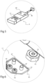
- Figs 4-6 show enlarged portions A, B, and C of fig 3 .
- the second structural element 13 comprises an opening in the form of a hole 15, through which the load sensor can connect to the first structural element 11.
- the opening is a hole in the second structural element 13, although in principle there could also be provided a cut-out from the edge of the first structural element 11 as indicated with dashed lines.
- an attachment part e.g. in the form of an attachment plate 41 on the side of the second structural element which faces the first structural element. This allows the load sensor 9 to be firmly connected to the second structural element 13 without making the latter flex significantly at this point.
- an opening 43 in the first structural element 11 which at least partly accommodates this attachment plate 41.
- the opening 43 is slightly wider than the extensions of the plate to allow some movement between the structural elements.
- the attachment plate 41 may be attached to the second structural element 13 by means of a first set of bolts 45 or by means e.g. of welding, and the load sensor may in turn be attached to the attachment plate 41 by means of a second set of bolts, through the second structural element.
- the load sensor shown in fig 5 , may be a planar beam load cell 9, and may comprise threaded openings 49 for the bolts 47, indicated in fig 6 and connecting to the second structural element 13, as well as an opening 51, which by means of a bolt (57, cf. fig 8 ) is connected to a nut and bolt configuration 53, 55, being firmly attached to the first structural element 11.
- Other load sensors than planar beam load cells are conceivable in this context as is known to the skilled person, for instance a piezo electric cell could be located in between the first and second structural elements 11, 13.
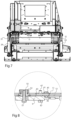
- Fig 7 shows a cross-section through the suspension arrangement 29, 31 as illustrated in fig 2 and as seen from the side of the washing machine.
- Fig 8 shows enlarged the portion D of fig 7 , which illustrates a load sensor 9 in the form of a planar load cell connecting a first structural element 11, in the form of a sheet metal plate, to a second structural element 13, also in the form of a sheet metal plate.
- the load sensor 9 is attached to the second structural element 13 by means of an attachment plate 41 on the opposite side of the second structural element 13.
- the attachment plate 41 is screwed to the second structural element 13 by means of bolts 45, and the load sensor 9 is attached, at one end, to the attachment plate 41 and the structural element by means of another set of bolts 47.
- the attachment plate 41 reaches into an opening 43 in the first structural element 11 to allow the structural elements to be placed closer to one another.
- This opening 43 is slightly bigger than the plate 41, such that that the latter can move slightly without touching the first structural element 11.
- the other end of the load sensor 9 is connected to a bolt and screw combination 53, 55, which is attached to the first structural element 11 by clasping the rim of an opening therein.
- the load sensor 9 is attached thereto by means of a bolt 57 which is screwed into a threaded opening in the bolt 53 attached to the first structural element 11.
- Fig 9 schematically shows a washing machine having load sensors arranged on the drum's side of a suspension arrangement.
- a suspension arrangement 29, 31 carries the drum in relation to a base structure 7 located under the washing machine on which the washing machine rests.
- a load sensing device 9, configured to sense the load of the drum 3 is provided.
- the load sensing device 9 is located on the opposite side of the suspension arrangement 29, 31 as seen from the base structure 7.
Landscapes
- Engineering & Computer Science (AREA)
- Textile Engineering (AREA)
- Main Body Construction Of Washing Machines And Laundry Dryers (AREA)
- Control Of Washing Machine And Dryer (AREA)
- Detail Structures Of Washing Machines And Dryers (AREA)
Description
- The present invention relates to a laundry washing machine comprising a rotatable drum, a suspension arrangement carrying the drum in relation to a base structure located under the washing machine and on which the washing machine rests, and a load sensing device, configured to sense the load of the drum.
- Such a washing machine is disclosed for instance in
WO-2012/089442-A1 where load cells are located in a frame in the bottom of the machine. Such load cells can be used to weigh the amount of laundry loaded into the drum, allowing the washing cycle to be adapted thereto. - One problem associated with washing machines of this type is how to make the machine capable of carrying out a more adaptable washing cycle that is more efficient.
-
Patent application WO 2010/133510 A1 discloses a horizontal axis washing machine (1) comprising a body (2), a drum which is disposed inside the body (2), rotates in the horizontal axis and wherein items to be washed are placed, and a tub (3) wherein the drum rotates; and wherein the amount of water to counterbalance the unbalanced load and minimizeits effect is continuously delivered to the desired place in the case of an unbalanced load. -
Patent application WO 2012/089442 A1 discloses a washing machine (1) comprising a drum (3) which is disposed in the body (2) and rotates around the horizontal axis, and wherein items to be washed are placed, a tub (4) wherein the drum (3) moves and which oscillates together with the drum (3) during the operation, two support blocks (5) which extend in the body (2) from the front backwards oppositely in the horizontal direction at the bottom side of the drum (3) at its right and left sides, more than one shock absorber (6), one end of which is connected to the tub (4) and the other end to the support block (5) and which absorbs the vibration movements of the tub (4), more than one shock absorber pin (7) which connects the lower ends of the shock absorbers (6) to the support block (5), a lower frame (8) which is located at the bottom side of the body (2) and supported by the feet seated on the floor, and whereon the support blocks (5), are seated and which, together with the support blocks (5), supports the weight of the tub (4), of the drum (3) and of the drum (3) motor, and load sensors (9) which provide weight and unbalanced load detection to be performed. -
Patent application EP 3 222768A1 - One object of the present invention is therefore to provide a washing machine with a load sensor that provides more versatile data.
- This object is achieved by means of a washing machine as defined in
claim 1. More particularly, in a washing machine of the initially mentioned kind, there is provided a first structural element, which is connected to either of the housing and the suspension arrangement, and a second structural element which is connected to the other of the housing and the suspension arrangement. The first and second structural elements extend in first and second planes, respectively, which are mutually parallel. Further, the load sensing device, which may typically be a planar beam load cell, is attached to the second structural element on a surface thereof facing away from the first structural element and is connected to the first structural element. - This allows a very compact arrangement, as there is only needed a small gap between the first and second structural elements, which is bridged by the load sensor. The load sensing arrangement is nevertheless capable of measuring the load in between the drum and the suspension arrangement which provides improved load sensing data, which may be used for a more adaptive control of the washing machine.
- The second structural element may comprise an opening, and the load sensing device may be connected to the first structural element through the opening. This allows the first and second structural elements to be connected to each other via the load sensing device, without the latter being mounted between the first and second structural elements.
- The load sensing device may be attached to the second structural element by means of an attachment part such as an attachment plate, which is attached to the second structural element on a surface thereof facing towards the first structural element. This provides a firm attachment point on the second structural element even if this element consists of a relatively thin metal plate.
- There may be provided an opening in the first structural element which at least partly accommodates the attachment part. This allows the first and second structural elements to be located very close to each other without the attachment part touching the first structural element. The attachment part may be positioned in a stamped recess in the second structural element to offset the load sensing device slightly from the remainder of the second structural element to facilitate the load sensing device's bending, slightly towards the latter.
- There is provided three or more sensing devices in between the suspension arrangement and the drum.
- The sensing device may be a planar beam load cell, although other load sensing devices are conceivable in this context.
- There is provided a door for gaining access to the interior of the drum, and the door is suspended by the suspension arrangement. This may be achieved for instance by attaching the door to a housing, which contains the rotatable drum and is carried via the sensing arrangement. This means that no connections, by bellows or the like, between suspended and non-suspended parts are needed to arrange the door, which reduces disturbances on the load measuring.
-
-
Fig 1 shows a perspective view of a washing machine. -
Fig 2 shows a perspective view of suspension arrangement carrying a drum. -
Fig 3 shows a partially exploded view of a drum cradle in the suspension arrangement offig 2 . -
Figs 4-6 show enlarged portions A, B, and C offig 3 . -
Fig 7 shows a cross-section through a suspension arrangement as illustrated infig 2 and as seen from the side of the washing machine. -
Fig 8 shows enlarged portion D offig 7 . -
Fig 9 schematically shows a washing machine having load sensors arranged on the drum's side of a suspension arrangement. - The present disclosure relates generally to a
washing machine 1, an example of which is shown infig 1 . The washing machine comprises anouter housing 19 and rests on a base structure 7, which is typically a floor, but in principle could be a rack or another machine, for instance. At afront side 21 of the washing machine, there is located adoor 23 through which the interior of a drum is accessible. -
Fig 2 shows a suspension arrangement carrying arotatable drum 3 inside thehousing 19 offig 1 . Therotatable drum 3 is located inside a typicallycylindrical housing 25, which is carried by adrum cradle arrangement 27, which in turn is carried by asuspension arrangement dampers 29 andsprings 31 connecting the cradle arrangement to abottom part 33 of the machine that rests on the base structure/floor 7. Typically, one damper/spring combination is used in each corner. - As illustrated, at delivery, the
cradle arrangement 27 may be firmly connected to thebottom part 33 by means oftransport lock plates 35, which are removed before the washing machine is used. -
Weights 37 may be added to the cradle arrangement to obtain suitable spring-mass system properties. - As shown, the
door 23, used for gaining access to the interior of thedrum 3, may be suspended by the suspension arrangement, i.e. is attached to thecylindrical housing 25 in which therotatable drum 3 moves, rather than to theouter housing 19 of the machine. This means that there is one fewer part disturbing the collecting of load data, as will be described. If instead a door for instance would be attached to theouter housing 19 providing an opening that is connected to thecylindrical housing 25 by means of a bellow, that connection between a part suspended by the suspension arrangement and a non-suspended part would impair the load measurements as some load would be carried via the bellow rather than via the load sensors. -
Fig 3 shows a partially exploded view of a drum cradle in the suspension arrangement offig 2 . As shown, there is on each side provided a firststructural element 11 which is connected to the drum of the machine, which is kept in place by bands 39. The firststructural element 11 may as shown be in the form of a sheet metal plate, which substantially extends in a first plane in a first portion although it may be bent to form other parts of the cradle. - There is provided, as shown in the exploded view on the right side, a second
structural element 13, which is connected to the suspension arrangement (29, 31 cf.fig 2 ). The secondstructural element 13 may as well be in the form of a sheet metal plate, and this plate may substantially extend in a second plane, which is parallel with the first plane, i.e. the plane of the firststructural element 11, at a location where they are interconnected as will be shown. - The first and second
structural elements load sensors 9 that together sense the load on the drum. There is thus provided a gap between the first and secondstructural elements load sensors 9. Typically, three or moresuch load sensors 9 are used, in the illustrated case four arranged in corners of a rectangle as seen from the top of the washing machine. - As this sensing is done on the drum's 3 side of the
suspension arrangement -
Figs 4-6 show enlarged portions A, B, and C offig 3 . To start with, the arrangement used to attach theload sensor 9 to the secondstructural element 13 is shown infig 4 . The secondstructural element 13 comprises an opening in the form of ahole 15, through which the load sensor can connect to the firststructural element 11. In the illustrated case, the opening is a hole in the secondstructural element 13, although in principle there could also be provided a cut-out from the edge of the firststructural element 11 as indicated with dashed lines. In principle there could also be provided an arrangement that connects the load sensor to the first structural element around the side edge of the firststructural element 13. It should be noted though, that the illustrated embodiment with ahole 15 in the sheet metal plate forming the first structural element allows a both strong and compact connecting arrangement. - As the
load sensor 9 will be required to take up significant loads it should be firmly connected to the secondstructural element 13. In order to avoid using a thick sheet metal piece to form the secondstructural element 13, there may be provided an attachment part e.g. in the form of anattachment plate 41 on the side of the second structural element which faces the first structural element. This allows theload sensor 9 to be firmly connected to the secondstructural element 13 without making the latter flex significantly at this point. - As shown in
fig 6 , there may be arranged anopening 43 in the firststructural element 11 which at least partly accommodates thisattachment plate 41. Theopening 43 is slightly wider than the extensions of the plate to allow some movement between the structural elements. This arrangement allows the first and secondstructural elements attachment plate 41 may be attached to the secondstructural element 13 by means of a first set ofbolts 45 or by means e.g. of welding, and the load sensor may in turn be attached to theattachment plate 41 by means of a second set of bolts, through the second structural element. - The load sensor, shown in
fig 5 , may be a planarbeam load cell 9, and may comprise threadedopenings 49 for thebolts 47, indicated infig 6 and connecting to the secondstructural element 13, as well as an opening 51, which by means of a bolt (57, cf.fig 8 ) is connected to a nut andbolt configuration structural element 11. Other load sensors than planar beam load cells are conceivable in this context as is known to the skilled person, for instance a piezo electric cell could be located in between the first and secondstructural elements -
Fig 7 shows a cross-section through thesuspension arrangement fig 2 and as seen from the side of the washing machine. -
Fig 8 shows enlarged the portion D offig 7 , which illustrates aload sensor 9 in the form of a planar load cell connecting a firststructural element 11, in the form of a sheet metal plate, to a secondstructural element 13, also in the form of a sheet metal plate. As shown, theload sensor 9 is attached to the secondstructural element 13 by means of anattachment plate 41 on the opposite side of the secondstructural element 13. There may be formed a stampedrecess 40 in the plate forming the secondstructural element 13 at the location of theattachment plate 41 such that theload sensor 9 is slightly offset from the secondstructural element 13, except where attached thereto. This allows the load sensor to flex towards the secondstructural element 13 even if being flat. This offset could also be achieved also with another attachment plate, on the load sensor's side. - The
attachment plate 41 is screwed to the secondstructural element 13 by means ofbolts 45, and theload sensor 9 is attached, at one end, to theattachment plate 41 and the structural element by means of another set ofbolts 47. As can be seen, theattachment plate 41 reaches into anopening 43 in the firststructural element 11 to allow the structural elements to be placed closer to one another. Thisopening 43 is slightly bigger than theplate 41, such that that the latter can move slightly without touching the firststructural element 11. - The other end of the
load sensor 9 is connected to a bolt and screwcombination structural element 11 by clasping the rim of an opening therein. Theload sensor 9 is attached thereto by means of abolt 57 which is screwed into a threaded opening in thebolt 53 attached to the firststructural element 11. -
Fig 9 schematically shows a washing machine having load sensors arranged on the drum's side of a suspension arrangement. Thus, in a laundry washing machine comprising arotatable drum 3, asuspension arrangement load sensing device 9, configured to sense the load of thedrum 3 is provided. Theload sensing device 9 is located on the opposite side of thesuspension arrangement - The present disclosure is not restricted to the above-described embodiment and may be varied and altered in different ways within the scope of the appended claims.
Claims (9)
- A laundry washing machine (1) comprising a rotatable drum (3) inside a housing (25), a suspension arrangement (29, 31) carrying the housing (25) in relation to a base structure, located under the washing machine and on which the washing machine (1) is adapted to rest, and a load sensing device (9), configured to sense the load of the drum (3); characterized by:a first structural element (11) substantially extending in a first plane and being connected to either of the housing (25) and the suspension arrangement (29, 31), anda second structural element (13) substantially extending in a second plane, which is parallel with the first plane, and being connected to the other of the housing (25) and the suspension arrangement (29, 31),wherein the load sensing device (9) is attached to the second structural element (13) on a surface thereof facing away from the first structural element (11) and is connected to the first structural element (11).
- A laundry washing machine according to claim 1, wherein the second structural element (13) comprises an opening (15), and the load sensing device (9) is connected to the first structural element (11) through the opening (15).
- A laundry washing machine according to claim 1 or 2, wherein the load sensing device (9) is attached to the second structural element (13) by means of an attachment part, such as an attachment plate (41), which is attached to the second structural element (13) on a surface thereof facing towards the first structural element (11).
- A laundry washing machine according to claim 3, wherein there is arranged an opening (43) in the first structural element (11) which at least partly accommodates the attachment part.
- A laundry washing machine according to claim 3 or 4, wherein the attachment part is positioned in a stamped recess (40) in the second structural element (13).
- A laundry washing machine according to any of the preceding claims, wherein there is provided three or more sensing devices (9) in between the suspension arrangement (29, 31) and the drum (3).
- A laundry washing machine according to any of the preceding claims, wherein the sensing device (9) is a planar beam load cell.
- A laundry washing machine according to any of the preceding claims, wherein there is provided a door (23) for gaining access to the interior of the drum (3), and the door (23) is suspended by the suspension arrangement (29, 31).
- A laundry washing machine according to claim 8, wherein the door (23) is attached to the housing (25).
Applications Claiming Priority (1)
| Application Number | Priority Date | Filing Date | Title |
|---|---|---|---|
| PCT/EP2018/063764 WO2019223877A1 (en) | 2018-05-25 | 2018-05-25 | Washing machine |
Publications (3)
| Publication Number | Publication Date |
|---|---|
| EP3802941A1 EP3802941A1 (en) | 2021-04-14 |
| EP3802941C0 EP3802941C0 (en) | 2025-05-21 |
| EP3802941B1 true EP3802941B1 (en) | 2025-05-21 |
Family
ID=62455456
Family Applications (1)
| Application Number | Title | Priority Date | Filing Date |
|---|---|---|---|
| EP18728088.8A Active EP3802941B1 (en) | 2018-05-25 | 2018-05-25 | Washing machine |
Country Status (8)
| Country | Link |
|---|---|
| US (1) | US11920279B2 (en) |
| EP (1) | EP3802941B1 (en) |
| JP (1) | JP7165212B2 (en) |
| KR (1) | KR102547840B1 (en) |
| CN (1) | CN112135936A (en) |
| AU (1) | AU2018424296B2 (en) |
| ES (1) | ES3038127T3 (en) |
| WO (1) | WO2019223877A1 (en) |
Families Citing this family (3)
| Publication number | Priority date | Publication date | Assignee | Title |
|---|---|---|---|---|
| JP2025095481A (en) * | 2023-12-14 | 2025-06-26 | 三星電子株式会社 | washing machine |
| WO2025135972A1 (en) * | 2023-12-22 | 2025-06-26 | 엘지전자 주식회사 | Clothing processing device |
| DE102024207925A1 (en) * | 2024-08-21 | 2026-02-26 | BSH Hausgeräte GmbH | Household appliance for the care of laundry items |
Family Cites Families (13)
| Publication number | Priority date | Publication date | Assignee | Title |
|---|---|---|---|---|
| JP2003093790A (en) | 2001-09-25 | 2003-04-02 | Sanyo Electric Co Ltd | Drum type washing machine |
| JP2004353749A (en) | 2003-05-28 | 2004-12-16 | Tokico Ltd | Damper with load detection function |
| ES2318450T3 (en) | 2005-02-02 | 2009-05-01 | Girbau, S.A. | SUPPORT STRUCTURE FOR WASHING MACHINE. |
| KR101549009B1 (en) | 2009-03-19 | 2015-09-01 | 엘지전자 주식회사 | Dryer with weight sensing device and dryer control method using same |
| WO2010133510A1 (en) * | 2009-05-22 | 2010-11-25 | Arcelik Anonim Sirketi | A horizontal axis washing machine |
| US20110127091A1 (en) * | 2009-11-27 | 2011-06-02 | Shepherdson Robin | Planar Beam Load Cell Assembly |
| EP2659050B1 (en) * | 2010-12-27 | 2015-10-14 | Arçelik Anonim Sirketi | Washing machine comprising a load sensor |
| AU2013204355B2 (en) * | 2012-12-21 | 2016-10-27 | Fisher & Paykel Appliances Limited | Improved laundry appliance |
| CN103628277A (en) | 2013-09-23 | 2014-03-12 | 无锡小天鹅股份有限公司 | Washing machine |
| KR102390026B1 (en) * | 2015-03-20 | 2022-04-25 | 엘지전자 주식회사 | Washing machine |
| EP3222768B1 (en) | 2016-03-22 | 2019-03-20 | Electrolux Appliances Aktiebolag | Laundry machine |
| CN107692944A (en) | 2016-08-08 | 2018-02-16 | 迪尔阿扣基金两合公司 | Sensor device and the electrical equipment for being used to wash provided with the sensor device |
| JP2018061552A (en) * | 2016-10-11 | 2018-04-19 | 東芝ライフスタイル株式会社 | Drum-type washing machine |
-
2018
- 2018-05-25 CN CN201880093579.7A patent/CN112135936A/en active Pending
- 2018-05-25 ES ES18728088T patent/ES3038127T3/en active Active
- 2018-05-25 JP JP2020564848A patent/JP7165212B2/en active Active
- 2018-05-25 WO PCT/EP2018/063764 patent/WO2019223877A1/en not_active Ceased
- 2018-05-25 EP EP18728088.8A patent/EP3802941B1/en active Active
- 2018-05-25 US US17/056,754 patent/US11920279B2/en active Active
- 2018-05-25 AU AU2018424296A patent/AU2018424296B2/en active Active
- 2018-05-25 KR KR1020207036658A patent/KR102547840B1/en active Active
Also Published As
| Publication number | Publication date |
|---|---|
| KR20210029154A (en) | 2021-03-15 |
| AU2018424296A1 (en) | 2020-11-26 |
| EP3802941C0 (en) | 2025-05-21 |
| AU2018424296B2 (en) | 2024-09-05 |
| ES3038127T3 (en) | 2025-10-09 |
| JP2021524779A (en) | 2021-09-16 |
| JP7165212B2 (en) | 2022-11-02 |
| WO2019223877A1 (en) | 2019-11-28 |
| US20210207308A1 (en) | 2021-07-08 |
| EP3802941A1 (en) | 2021-04-14 |
| KR102547840B1 (en) | 2023-06-26 |
| US11920279B2 (en) | 2024-03-05 |
| CN112135936A (en) | 2020-12-25 |
Similar Documents
| Publication | Publication Date | Title |
|---|---|---|
| RU2245528C2 (en) | Device for measuring forces, oppearing because of rotor disbalance | |
| US8312581B2 (en) | Method for determining the load in a washing machine | |
| EP0129249B1 (en) | Weighing machine | |
| MXPA02010660A (en) | Load carrying means for cable operated elevators with an integrated load measurement device. | |
| EP2072653A1 (en) | Washing machine with anti-vibration device | |
| EP1419295B1 (en) | Washing machine with imbalance monitoring sensor | |
| US11920279B2 (en) | Washing machine | |
| US20080295545A1 (en) | Dynamic Vibration Absorber | |
| RU2011120251A (en) | GRAVITY GRADIOMETER WITH TORSION BENDING RODS | |
| WO2008085012A2 (en) | Laundry machine | |
| US6141888A (en) | Monitoring wood sample weight with mechanical force proportioning | |
| HK40040208A (en) | Washing machine | |
| HK40040208B (en) | Washing machine | |
| EP2504480A1 (en) | Laundry treating machine provided with a vibration damper device | |
| JPH0752592Y2 (en) | electronic balance | |
| ES2690983T3 (en) | Procedure to determine a load weight of a vibrating system of a household appliance for the care of laundry and household appliances | |
| JPS603524A (en) | Weight measuring device | |
| US20110023556A1 (en) | Suspension System for Washing Machines | |
| EP2432927B1 (en) | A horizontal axis washing machine | |
| US4333322A (en) | Mount for washing machine | |
| US4815548A (en) | Counterbalanced weighing apparatus | |
| JP2024099444A (en) | Drum washing machine | |
| GB1598210A (en) | Laundry washing machine | |
| EP2818592B1 (en) | Washing Machine | |
| EP1382733B1 (en) | Washing machine with a washing unit |
Legal Events
| Date | Code | Title | Description |
|---|---|---|---|
| STAA | Information on the status of an ep patent application or granted ep patent |
Free format text: STATUS: UNKNOWN |
|
| STAA | Information on the status of an ep patent application or granted ep patent |
Free format text: STATUS: THE INTERNATIONAL PUBLICATION HAS BEEN MADE |
|
| PUAI | Public reference made under article 153(3) epc to a published international application that has entered the european phase |
Free format text: ORIGINAL CODE: 0009012 |
|
| STAA | Information on the status of an ep patent application or granted ep patent |
Free format text: STATUS: REQUEST FOR EXAMINATION WAS MADE |
|
| 17P | Request for examination filed |
Effective date: 20201120 |
|
| AK | Designated contracting states |
Kind code of ref document: A1 Designated state(s): AL AT BE BG CH CY CZ DE DK EE ES FI FR GB GR HR HU IE IS IT LI LT LU LV MC MK MT NL NO PL PT RO RS SE SI SK SM TR |
|
| AX | Request for extension of the european patent |
Extension state: BA ME |
|
| REG | Reference to a national code |
Ref country code: HK Ref legal event code: DE Ref document number: 40040208 Country of ref document: HK |
|
| DAV | Request for validation of the european patent (deleted) | ||
| DAX | Request for extension of the european patent (deleted) | ||
| STAA | Information on the status of an ep patent application or granted ep patent |
Free format text: STATUS: EXAMINATION IS IN PROGRESS |
|
| 17Q | First examination report despatched |
Effective date: 20230414 |
|
| GRAP | Despatch of communication of intention to grant a patent |
Free format text: ORIGINAL CODE: EPIDOSNIGR1 |
|
| STAA | Information on the status of an ep patent application or granted ep patent |
Free format text: STATUS: GRANT OF PATENT IS INTENDED |
|
| INTG | Intention to grant announced |
Effective date: 20241127 |
|
| GRAS | Grant fee paid |
Free format text: ORIGINAL CODE: EPIDOSNIGR3 |
|
| RAP3 | Party data changed (applicant data changed or rights of an application transferred) |
Owner name: ELECTROLUX PROFESSIONAL AB (PUBL) |
|
| GRAA | (expected) grant |
Free format text: ORIGINAL CODE: 0009210 |
|
| STAA | Information on the status of an ep patent application or granted ep patent |
Free format text: STATUS: THE PATENT HAS BEEN GRANTED |
|
| AK | Designated contracting states |
Kind code of ref document: B1 Designated state(s): AL AT BE BG CH CY CZ DE DK EE ES FI FR GB GR HR HU IE IS IT LI LT LU LV MC MK MT NL NO PL PT RO RS SE SI SK SM TR |
|
| REG | Reference to a national code |
Ref country code: GB Ref legal event code: FG4D |
|
| REG | Reference to a national code |
Ref country code: CH Ref legal event code: EP |
|
| REG | Reference to a national code |
Ref country code: IE Ref legal event code: FG4D |
|
| U01 | Request for unitary effect filed |
Effective date: 20250521 |
|
| U07 | Unitary effect registered |
Designated state(s): AT BE BG DE DK EE FI FR IT LT LU LV MT NL PT RO SE SI Effective date: 20250527 |
|
| PGFP | Annual fee paid to national office [announced via postgrant information from national office to epo] |
Ref country code: GB Payment date: 20250613 Year of fee payment: 8 |
|
| PGFP | Annual fee paid to national office [announced via postgrant information from national office to epo] |
Ref country code: CH Payment date: 20250617 Year of fee payment: 8 |
|
| U20 | Renewal fee for the european patent with unitary effect paid |
Year of fee payment: 8 Effective date: 20250613 |
|
| PGFP | Annual fee paid to national office [announced via postgrant information from national office to epo] |
Ref country code: ES Payment date: 20250701 Year of fee payment: 8 |
|
| REG | Reference to a national code |
Ref country code: ES Ref legal event code: FG2A Ref document number: 3038127 Country of ref document: ES Kind code of ref document: T3 Effective date: 20251009 |
|
| PG25 | Lapsed in a contracting state [announced via postgrant information from national office to epo] |
Ref country code: GR Free format text: LAPSE BECAUSE OF FAILURE TO SUBMIT A TRANSLATION OF THE DESCRIPTION OR TO PAY THE FEE WITHIN THE PRESCRIBED TIME-LIMIT Effective date: 20250822 |
|
| PGFP | Annual fee paid to national office [announced via postgrant information from national office to epo] |
Ref country code: NO Payment date: 20250627 Year of fee payment: 8 |
|
| PG25 | Lapsed in a contracting state [announced via postgrant information from national office to epo] |
Ref country code: PL Free format text: LAPSE BECAUSE OF FAILURE TO SUBMIT A TRANSLATION OF THE DESCRIPTION OR TO PAY THE FEE WITHIN THE PRESCRIBED TIME-LIMIT Effective date: 20250521 |
|
| PGFP | Annual fee paid to national office [announced via postgrant information from national office to epo] |
Ref country code: TR Payment date: 20250814 Year of fee payment: 8 |
|
| PG25 | Lapsed in a contracting state [announced via postgrant information from national office to epo] |
Ref country code: HR Free format text: LAPSE BECAUSE OF FAILURE TO SUBMIT A TRANSLATION OF THE DESCRIPTION OR TO PAY THE FEE WITHIN THE PRESCRIBED TIME-LIMIT Effective date: 20250521 |
|
| PG25 | Lapsed in a contracting state [announced via postgrant information from national office to epo] |
Ref country code: RS Free format text: LAPSE BECAUSE OF FAILURE TO SUBMIT A TRANSLATION OF THE DESCRIPTION OR TO PAY THE FEE WITHIN THE PRESCRIBED TIME-LIMIT Effective date: 20250821 |
|
| PGFP | Annual fee paid to national office [announced via postgrant information from national office to epo] |
Ref country code: CZ Payment date: 20250711 Year of fee payment: 8 |
|
| PG25 | Lapsed in a contracting state [announced via postgrant information from national office to epo] |
Ref country code: IS Free format text: LAPSE BECAUSE OF FAILURE TO SUBMIT A TRANSLATION OF THE DESCRIPTION OR TO PAY THE FEE WITHIN THE PRESCRIBED TIME-LIMIT Effective date: 20250921 |
|
| PG25 | Lapsed in a contracting state [announced via postgrant information from national office to epo] |
Ref country code: SM Free format text: LAPSE BECAUSE OF FAILURE TO SUBMIT A TRANSLATION OF THE DESCRIPTION OR TO PAY THE FEE WITHIN THE PRESCRIBED TIME-LIMIT Effective date: 20250521 |
|
| PG25 | Lapsed in a contracting state [announced via postgrant information from national office to epo] |
Ref country code: SK Free format text: LAPSE BECAUSE OF FAILURE TO SUBMIT A TRANSLATION OF THE DESCRIPTION OR TO PAY THE FEE WITHIN THE PRESCRIBED TIME-LIMIT Effective date: 20250521 |
|
| PG25 | Lapsed in a contracting state [announced via postgrant information from national office to epo] |
Ref country code: MC Free format text: LAPSE BECAUSE OF FAILURE TO SUBMIT A TRANSLATION OF THE DESCRIPTION OR TO PAY THE FEE WITHIN THE PRESCRIBED TIME-LIMIT Effective date: 20250521 |
|
| PLBE | No opposition filed within time limit |
Free format text: ORIGINAL CODE: 0009261 |
|
| STAA | Information on the status of an ep patent application or granted ep patent |
Free format text: STATUS: NO OPPOSITION FILED WITHIN TIME LIMIT |
|
| REG | Reference to a national code |
Ref country code: CH Ref legal event code: L10 Free format text: ST27 STATUS EVENT CODE: U-0-0-L10-L00 (AS PROVIDED BY THE NATIONAL OFFICE) Effective date: 20260402 |
|
| PG25 | Lapsed in a contracting state [announced via postgrant information from national office to epo] |
Ref country code: IE Free format text: LAPSE BECAUSE OF NON-PAYMENT OF DUE FEES Effective date: 20250525 |
|
| 26N | No opposition filed |
Effective date: 20260224 |
|
| U20 | Renewal fee for the european patent with unitary effect paid |
Year of fee payment: 9 Effective date: 20260401 |