EP3802328B1 - Efficient satellite structure concept for single or stacking multiple launches - Google Patents
Efficient satellite structure concept for single or stacking multiple launches Download PDFInfo
- Publication number
- EP3802328B1 EP3802328B1 EP19722590.7A EP19722590A EP3802328B1 EP 3802328 B1 EP3802328 B1 EP 3802328B1 EP 19722590 A EP19722590 A EP 19722590A EP 3802328 B1 EP3802328 B1 EP 3802328B1
- Authority
- EP
- European Patent Office
- Prior art keywords
- satellite
- paf
- satellite structure
- interfaces
- dedicated
- Prior art date
- Legal status (The legal status is an assumption and is not a legal conclusion. Google has not performed a legal analysis and makes no representation as to the accuracy of the status listed.)
- Active
Links
Images



Classifications
-
- B—PERFORMING OPERATIONS; TRANSPORTING
- B64—AIRCRAFT; AVIATION; COSMONAUTICS
- B64G—COSMONAUTICS; VEHICLES OR EQUIPMENT THEREFOR
- B64G1/00—Cosmonautic vehicles
- B64G1/10—Artificial satellites; Systems of such satellites; Interplanetary vehicles
- B64G1/1085—Swarms and constellations
-
- B—PERFORMING OPERATIONS; TRANSPORTING
- B64—AIRCRAFT; AVIATION; COSMONAUTICS
- B64G—COSMONAUTICS; VEHICLES OR EQUIPMENT THEREFOR
- B64G1/00—Cosmonautic vehicles
- B64G1/22—Parts of, or equipment specially adapted for fitting in or to, cosmonautic vehicles
- B64G1/64—Systems for coupling or separating cosmonautic vehicles or parts thereof, e.g. docking arrangements
- B64G1/641—Interstage or payload connectors
- B64G1/643—Interstage or payload connectors for arranging multiple satellites in a single launcher
- B64G1/644—Interstage or payload connectors for arranging multiple satellites in a single launcher arranged for independent deployment
Definitions
- the present invention relates, in general, to the technical sector of systems for deploying spacecraft's/satellites in orbit from launch vehicles and, more particularly, to an efficient satellite structure concept and its dedicated launcher interface, suitable for a single launch, or a stacking multiple launch, from a single launch vehicle.
- launch vehicles also simply known as launchers
- launchers are used to deploy spacecraft's/satellites in a predetermined orbit around the Earth.
- one or more systems for deploying one or more spacecraft and/or one or more satellites are typically used, each of which is generally configured to:
- US 8,915,472 B2 concerns a multiple space vehicle launch system and discloses a launch system composed of two satellites: a lower one and an upper one.
- the lower one is releasably attached to the upper stage of the launch vehicle by means of a standard ring interface and again releasably attached to the upper satellite by means of the same type of standard ring interface.
- the lower satellite bears the launch loads induced by the upper satellite, thereby eliminating the need for additional support structures (e.g., a dispenser).
- Both satellites include a central core structure bearing the main portion of the launch loads that is connected to the ring interfaces.
- US 9,669,948 B2 relates to a side-by-side dual-launch spacecraft arrangement and discloses a launch system composed of two satellites placed side-by-side on a dual-launch adaptor. Both satellites are releasably attached to the dual-launch adaptor by means of a standard ring interface. The dual-launch adaptor is mounted on the last stage of the launch vehicle by means of a standard ring interface. Both satellites include a central core structure bearing the main portion of the launch loads connected to the ring interface.
- the spacecraft can be simplified as a cantilever beam subject to inertial loads induced by the launcher. It is evident that the external satellite structures are more effective for bearing the launch loads due to their higher area moment of inertia opposed to central core structures (with cross-section dimension lower than external satellite structures cross-section dimension).
- the area moment of inertia is a key factor in structural stiffness and strength.
- the typical external surfaces of a satellite are plane, to provide the simplest and most efficient support for internal electronic units and external thermal radiators. This implies the need to introduce a dedicated launcher interface that can provide the load transition mean from the corners among the plane surfaces and the launch vehicle bolted interface.
- the present invention allows a more complete exploitation of the mass capability of the launch vehicle in conjunction with a dedicated launcher interface that is relatively light and compact and remains connected to the launch vehicle after satellite separation with Earth re-entry or graveyard disposal of itself.
- the satellite structural concept according to the present invention comprises an external load-bearing structure, typically with square or rectangular base (but also other shapes may be conveniently used).
- the structure includes external vertical plane panels 1 connected by vertical beams 2.
- the external vertical plane panels 1 can be realized in any material typically used for satellite manufacturing (i.e., aluminium, aluminium sandwich, carbon fiber reinforced thermoplastic (CFRP) monocoque, CFRP sandwich, titanium, etc., or a combination thereof).
- CFRP carbon fiber reinforced thermoplastic
- the vertical panels 1 are connected by means of four (or even more) corner beams 2.
- the corner beams 2 may have any cross-section (typically, square, rectangular or circular) and can be realized in any material typically used for satellite manufacturing.
- the corner beams 2 have releasable interfaces at their bottom and upper edges 8.
- Internal vertical shear panels 3 and horizontal platform panels 4 may also be used for structural or equipment accommodation convenience.
- a bottom transition structure (or Payload Attaching Fitting - PAF) 5 completes the concept.
- the upper part of the PAF 5 there are a discrete number of releasable interfaces 6 with each corner beam 2 of the satellite structure and in the lower part there is a bolted interface 7 with the upper stage of the launch vehicle (not shown in Figure 1 ).
- the lower part of the separation system is mounted on a frame 17 that can be mounted and dismounted by means of a bolted interface on the PAF 18, or on the lower satellite of the stack 19.
- the stacking of the satellites can be realized as a single tower as shown in Figure 2 , mounted on the relevant PAF, or as a double tower, i.e., two towers arranged side-by-side, as shown in Figure 3 , mounted on the relevant PAF 20 designed to accommodate the two towers of satellites.
- the assembly architecture depends on the available fairing volume and mass capacity of the selected launcher.
- the releasable interfaces between stacked satellites and between the lower satellite(s) and the PAF are identical. These interfaces conveniently include:
- cup-cone interface 10 is capable to carry all local loads with exception of the axial traction load that is carried by the electro-actuated separation device(s) (e.g., NEA, Pyro-bolt, etc.).
- the electro-actuated separation device(s) e.g., NEA, Pyro-bolt, etc.
- the lowest connection of the stacking can use all the three (or more) separation devices 11.
- the upper connections 12 can use a lower number of separation devices due to the lower load levels.
- the external planar panels 1 may incorporate the corner beams 2; this is foreseeable if additive manufacturing technologies are used.
- the basic structural concept is equivalent to the known Truss Structure architecture made just of vertical and diagonal beams. Nevertheless, satellite external structures cannot be open with diagonal beams 13 as they are planar to accommodate the electronic equipment, act as thermal radiators and provide a close envelope for radiation shielding. This means that the structural reinforcement function, exerted by the diagonal beams, is performed by the sandwich panels. These panels, for structural optimisation reasons, may conveniently include reinforcement embedded structures or skin thickness reinforcements 23.
- the present invention which relates to a satellite structural concept with a mainly external load-carrying structure and its dedicated launcher interface, allows an efficient exploitation of the launch vehicle mass capability and satellite internal volume.
- This concept according to the present invention can be advantageously used for any space mission/orbit/launcher if deemed convenient.
Landscapes
- Engineering & Computer Science (AREA)
- Remote Sensing (AREA)
- Aviation & Aerospace Engineering (AREA)
- Physics & Mathematics (AREA)
- Astronomy & Astrophysics (AREA)
- General Physics & Mathematics (AREA)
- Details Of Aerials (AREA)
- Radio Relay Systems (AREA)
Description
- The present invention relates, in general, to the technical sector of systems for deploying spacecraft's/satellites in orbit from launch vehicles and, more particularly, to an efficient satellite structure concept and its dedicated launcher interface, suitable for a single launch, or a stacking multiple launch, from a single launch vehicle.
- As is known, launch vehicles (also simply known as launchers) are used to deploy spacecraft's/satellites in a predetermined orbit around the Earth. To this end, one or more systems for deploying one or more spacecraft and/or one or more satellites are typically used, each of which is generally configured to:
- during launch, securely and strongly hold down one or more spacecraft and/or one or more satellites stowed in an available volume of a launcher; and,
- when the launcher reaches a predefined position in orbit, deploy (i.e., release) the spacecraft/satellite(s) in response to a control signal.
- Some known solutions related to this sector are provided in
US 8,915,472 B2 ,US 9,669,948 B2 US 2016/0318635 A1 ,US 5,522,569 A ,EP 1 008 516 A1 ,US 2013/0099059 A1 andUS 2015/0151855 A1 . - In particular,
US 8,915,472 B2 concerns a multiple space vehicle launch system and discloses a launch system composed of two satellites: a lower one and an upper one. The lower one is releasably attached to the upper stage of the launch vehicle by means of a standard ring interface and again releasably attached to the upper satellite by means of the same type of standard ring interface. The lower satellite bears the launch loads induced by the upper satellite, thereby eliminating the need for additional support structures (e.g., a dispenser). Both satellites include a central core structure bearing the main portion of the launch loads that is connected to the ring interfaces. -
US 9,669,948 B2 - For a better understanding of the present invention, preferred embodiments, which are intended purely by way of non-limiting examples, will now be described with reference to the attached drawings (all not to scale), where:
-
Figure 1 schematically illustrates a satellite structure concept and a Payload Attaching Fitting (PAF) according to a preferred, non-limiting embodiment of the present invention; -
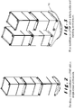
Figure 2 schematically illustrates stacking of three satellites on a PAF (with a single-tower architecture) according to a preferred, non-limiting embodiment of the present invention; -
Figure 3 schematically illustrates four satellites on a PAF (with a side-by-side architecture) according to a preferred, non-limiting embodiment of the present invention; -
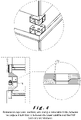
Figure 4 schematically illustrates a releasable cup-cone interface between two adjacent satellites or between the lower satellite and the PAF (with any architecture) according to a preferred, non-limiting embodiment of the present invention; -
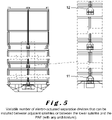
Figure 5 schematically illustrates a variable number of electro-actuated separation devices that can be installed between adjacent satellites or between the lower satellite and the PAF (with any architecture) according to a preferred, non-limiting embodiment of the present invention; -
Figure 6 schematically illustrates a releasable electrical connector and spring driven pushers installed at selected cup-cone separation interface according to a preferred, non-limiting embodiment of the present invention; -
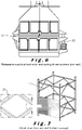
Figure 7 schematically illustrates a truss structure architecture concept according to a preferred, non-limiting embodiment of the present invention; -
Figure 8 schematically illustrates stacking of two satellites on a PAF (with single-tower architecture) according to a preferred, non-limiting embodiment of the present invention; -
Figure 9 schematically illustrates stacking of two satellites on a PAF (with side-by-side architecture) according to a preferred, non-limiting embodiment of the present invention; -
Figure 10 schematically illustrates a releasable interface between a generic satellite (having variable cross-section dimensions) and the same PAF according to non-limiting examples of the present invention; and -
Figure 11 schematically illustrates the lower part of the separation system mounted on a frame that can be mounted and dismounted by means of a bolted interface on a PAF or on the lower satellite of the stack according to non-limiting examples of the present invention. - The concept of the present invention is based on the following considerations. From a structural mechanics point of view, the spacecraft can be simplified as a cantilever beam subject to inertial loads induced by the launcher. It is evident that the external satellite structures are more effective for bearing the launch loads due to their higher area moment of inertia opposed to central core structures (with cross-section dimension lower than external satellite structures cross-section dimension). The area moment of inertia is a key factor in structural stiffness and strength.
- The typical external surfaces of a satellite are plane, to provide the simplest and most efficient support for internal electronic units and external thermal radiators. This implies the need to introduce a dedicated launcher interface that can provide the load transition mean from the corners among the plane surfaces and the launch vehicle bolted interface.
- In summary, the present invention allows a more complete exploitation of the mass capability of the launch vehicle in conjunction with a dedicated launcher interface that is relatively light and compact and remains connected to the launch vehicle after satellite separation with Earth re-entry or graveyard disposal of itself.
- The satellite structural concept according to the present invention comprises an external load-bearing structure, typically with square or rectangular base (but also other shapes may be conveniently used).
- With reference to
Figure 1 , the structure includes externalvertical plane panels 1 connected byvertical beams 2. The externalvertical plane panels 1 can be realized in any material typically used for satellite manufacturing (i.e., aluminium, aluminium sandwich, carbon fiber reinforced thermoplastic (CFRP) monocoque, CFRP sandwich, titanium, etc., or a combination thereof). - The
vertical panels 1 are connected by means of four (or even more)corner beams 2. Thecorner beams 2 may have any cross-section (typically, square, rectangular or circular) and can be realized in any material typically used for satellite manufacturing. Thecorner beams 2 have releasable interfaces at their bottom andupper edges 8. Internalvertical shear panels 3 andhorizontal platform panels 4 may also be used for structural or equipment accommodation convenience. - Always with reference to
Figure 1 , a bottom transition structure (or Payload Attaching Fitting - PAF) 5 completes the concept. In the upper part of thePAF 5, there are a discrete number ofreleasable interfaces 6 with eachcorner beam 2 of the satellite structure and in the lower part there is abolted interface 7 with the upper stage of the launch vehicle (not shown inFigure 1 ). - With reference to
Figure 10 , varioussatellite cross-section dimensions 14 can be accommodated on thesame PAF 15 with no need to redesign the latter. This is possible by changing the terminal angle of thevertical beams 16. - With reference to
Figure 11 , in order to facilitate transport, interface fit check and separation testing of satellites, the lower part of the separation system is mounted on aframe 17 that can be mounted and dismounted by means of a bolted interface on thePAF 18, or on the lower satellite of thestack 19. - The stacking of the satellites can be realized as a single tower as shown in
Figure 2 , mounted on the relevant PAF, or as a double tower, i.e., two towers arranged side-by-side, as shown inFigure 3 , mounted on therelevant PAF 20 designed to accommodate the two towers of satellites. The assembly architecture depends on the available fairing volume and mass capacity of the selected launcher. - The releasable interfaces between stacked satellites and between the lower satellite(s) and the PAF are identical. These interfaces conveniently include:
- with reference to
Figure 4 , mechanical interfaces including at least three cup-cone interfaces 10 connected at the edge of eachcorner beam 2; - with reference to
Figure 6 ,electrical harness interfaces 21 to provide communication with the launch vehicle and the ground support equipment; the releasable interfaces being equipped with brackets for electrical connectors; - micro-switches for satellite separation detection;
- again with reference to
Figure 6 ,systems 22 for ensuring spacecraft separation, typically spring driven separation pushers at selected separation interfaces to impart the necessary initial kinetic energy to the satellites after separation. - Again with reference to
Figure 4 , the cup-cone interface 10 is capable to carry all local loads with exception of the axial traction load that is carried by the electro-actuated separation device(s) (e.g., NEA, Pyro-bolt, etc.). - With reference to
Figure 5 , the lowest connection of the stacking (PAF-lower satellite) can use all the three (or more)separation devices 11. Theupper connections 12 can use a lower number of separation devices due to the lower load levels. - The external
planar panels 1 may incorporate the corner beams 2; this is foreseeable if additive manufacturing technologies are used. - With reference to
Figure 7 , the basic structural concept is equivalent to the known Truss Structure architecture made just of vertical and diagonal beams. Nevertheless, satellite external structures cannot be open withdiagonal beams 13 as they are planar to accommodate the electronic equipment, act as thermal radiators and provide a close envelope for radiation shielding. This means that the structural reinforcement function, exerted by the diagonal beams, is performed by the sandwich panels. These panels, for structural optimisation reasons, may conveniently include reinforcement embedded structures orskin thickness reinforcements 23. - Two preferred, non-limiting embodiments of the inventions are:
- 1) with reference to
Figure 8 , a single-tower architecture with the stacking of two identical satellites mounted on the dedicated PAF; - 2) with reference to
Figure 9 , a side-by-side architecture with two identical satellites mounted on the dedicated PAF. -
- a) In principle, as explained in the
paragraph 2 "Theoretic basis of the invention", the present invention is more efficient from a structural viewpoint with respect to the existing solutions (i.e., a certain stiffness performance level can be achieved with a lower structural mass). - b) The structural efficiency can be used in favour of an all-aluminium structure with higher performances concerning radiation shielding and cost reduction with respect to CFRP structures.
- c) The internal volume of the satellite is fully available for equipment accommodation, whereas this is not the case of a satellite with a large and long internal structural tube.
- d) The top and the bottom platforms of the satellite are completely available for equipment accommodation, whereas (again) this is not the case of a satellite with a large and long internal structural tube.
- e) The complexity of the present invention is limited to the compact PAF structure and interfaces and not to the large and long internal structural tubes.
- f) The cost of a limited number of pyros/NEA separation bolts is competitive with respect to the cost of two or more clamp-band systems.
- g) The separable interface can be more robust at the base of the satellite stacking, where the mechanical loads are higher, and less robust for the other separable interfaces of the stacking.
- In conclusion, it is worth noting that the present invention, which relates to a satellite structural concept with a mainly external load-carrying structure and its dedicated launcher interface, allows an efficient exploitation of the launch vehicle mass capability and satellite internal volume. This concept according to the present invention can be advantageously used for any space mission/orbit/launcher if deemed convenient.
Claims (4)
- System including a satellite structure and a dedicated Payload Attaching Fitting (5), PAF, for releasably attaching to said satellite structure, wherein the satellite structure comprises an external load-carrying structure, characterized in that the satellite structure includes external vertical planar panels (1) having internal reinforcements or embedded structures or skin thickness reinforcements (23), each configured for exerting the structural reinforcement function of diagonal beams in a truss structure architecture.
- The system of claim 1, wherein the satellite structure has a discrete number of interfaces, typically 3, 4 or more, for attaching to said dedicated Payload Attaching Fitting (5), PAF; and wherein the dedicated PAF (5) is mountable on a bolted interface of the upper stage of a launch vehicle.
- The system according to claim 1 or 2, wherein the satellite structure has identical bottom and upper discrete number of interfaces allowing the stacking of two or more satellites that can be identical to each other, or with different masses and heights.
- The system according to any preceding claim, wherein discrete interfaces between a satellite structure and the dedicated PAF (5), and/or between stacked satellite structures, are identical to each other and can be equipped, each, with one, two or more electro-actuated separation devices depending on local mechanical loads.
Applications Claiming Priority (2)
| Application Number | Priority Date | Filing Date | Title |
|---|---|---|---|
| EP18425039 | 2018-05-24 | ||
| PCT/EP2019/061440 WO2019223984A1 (en) | 2018-05-24 | 2019-05-03 | Efficient satellite structure concept for single or stacking multiple launches |
Publications (2)
| Publication Number | Publication Date |
|---|---|
| EP3802328A1 EP3802328A1 (en) | 2021-04-14 |
| EP3802328B1 true EP3802328B1 (en) | 2022-07-06 |
Family
ID=62750914
Family Applications (1)
| Application Number | Title | Priority Date | Filing Date |
|---|---|---|---|
| EP19722590.7A Active EP3802328B1 (en) | 2018-05-24 | 2019-05-03 | Efficient satellite structure concept for single or stacking multiple launches |
Country Status (8)
| Country | Link |
|---|---|
| US (1) | US11827384B2 (en) |
| EP (1) | EP3802328B1 (en) |
| JP (1) | JP7145975B2 (en) |
| CN (1) | CN112135777B (en) |
| BR (1) | BR112020022592A2 (en) |
| CA (1) | CA3099349A1 (en) |
| ES (1) | ES2926318T3 (en) |
| WO (1) | WO2019223984A1 (en) |
Families Citing this family (18)
| Publication number | Priority date | Publication date | Assignee | Title |
|---|---|---|---|---|
| US11834206B1 (en) * | 2017-04-13 | 2023-12-05 | Redwire Space, Inc. | Universal long-term in space structural erection system |
| US11794927B2 (en) | 2019-08-28 | 2023-10-24 | The Boeing Company | Additively manufactured spacecraft panel |
| US11802606B2 (en) | 2020-05-18 | 2023-10-31 | The Boeing Company | Planate dynamic isolator |
| US11827389B2 (en) * | 2020-05-18 | 2023-11-28 | The Boeing Company | Additively manufactured satellite |
| US12187461B2 (en) | 2020-07-08 | 2025-01-07 | Airbus Defence And Space Sas | Damped machined primary structure for a spacecraft, satellite incorporating this primary structure and method for manufacturing such a satellite |
| CA3140350A1 (en) | 2020-12-17 | 2022-06-17 | The Boeing Company | Satellite thermal enclosure |
| CA3140352A1 (en) | 2020-12-17 | 2022-06-17 | The Boeing Company | Stacked satellite assemblies and related methods |
| CN112693627A (en) * | 2021-01-05 | 2021-04-23 | 航天行云科技有限公司 | One-rocket multi-satellite stacked launching method |
| CN113022888B (en) * | 2021-05-28 | 2021-08-10 | 北京最终前沿深空科技有限公司 | Satellite structure and satellite assembly method |
| US11649074B1 (en) * | 2021-08-12 | 2023-05-16 | Blue Origin, Llc | Satellite dispensing system |
| CN114955015B (en) * | 2021-09-10 | 2025-02-07 | 北京空间飞行器总体设计部 | Mars exploration landing platform structure with complex and heavy loads |
| CN113911397B (en) * | 2021-09-30 | 2024-04-02 | 北京空间飞行器总体设计部 | A truss-type optical remote sensing load cabin main structure |
| ES3063606T3 (en) | 2021-11-10 | 2026-04-17 | Beyond Gravity Sweden Ab | A separable clamped hdrm interface for managing torsion loads |
| US12017808B2 (en) * | 2021-12-17 | 2024-06-25 | Maxar Space Llc | Dispenserless multi-satellite launch configuration with simple adapter interface |
| CN115196052B (en) * | 2022-07-13 | 2024-12-17 | 航天行云科技有限公司 | Fixing device of stacked satellite and control method thereof |
| CN116659318A (en) * | 2023-06-20 | 2023-08-29 | 航天科工火箭技术有限公司 | A multi-star adapter |
| CN119872920A (en) * | 2024-12-20 | 2025-04-25 | 中国空间技术研究院 | Modularized multifunctional satellite configuration |
| CN120817253B (en) * | 2025-09-17 | 2026-01-27 | 十方星链(苏州)航天科技有限公司 | Satellite assembly structure and satellite launch control methods |
Family Cites Families (27)
| Publication number | Priority date | Publication date | Assignee | Title |
|---|---|---|---|---|
| JPH0417504U (en) * | 1990-05-31 | 1992-02-13 | ||
| US5344104A (en) | 1992-09-21 | 1994-09-06 | General Electric Co. | Low cost, selectable configuration spacecraft |
| US5522569A (en) | 1994-02-04 | 1996-06-04 | Orbital Sciences Corporation | Satellite having a stackable configuration |
| US5529264A (en) * | 1994-02-18 | 1996-06-25 | Lockheed Missiles & Space Company, Inc. | Launch vehicle system |
| US5803402A (en) * | 1994-04-11 | 1998-09-08 | Composite Optics, Inc. | System and method for the construction of spacecraft structures |
| JP2000153800A (en) | 1998-11-19 | 2000-06-06 | Mitsubishi Electric Corp | Spacecraft separation mechanism |
| DE19856670B4 (en) | 1998-12-09 | 2004-12-02 | Eads Space Transportation Gmbh | Satellite launching device |
| RU2166588C1 (en) | 2000-09-29 | 2001-05-10 | Соболев Валериан Маркович | Heat-and-sound insulating building panel |
| RU29126U1 (en) | 2002-10-03 | 2003-04-27 | Открытое акционерное общество "Ковровский механический завод" | Flat solar housing |
| US20110296675A1 (en) * | 2009-08-26 | 2011-12-08 | Roopnarine | Means for rapidly assembling a spacecraft |
| FR2959490B1 (en) * | 2010-04-28 | 2012-07-13 | Astrium Sas | SATELLITE HAVING A SIMPLIFIED, ALLEGE AND ECONOMIC STRUCTURE AND ITS IMPLEMENTING METHOD |
| US8915472B2 (en) | 2012-05-11 | 2014-12-23 | The Boeing Company | Multiple space vehicle launch system |
| US8876062B1 (en) * | 2012-10-31 | 2014-11-04 | Space Systems/Loral, Llc | Shape memory alloy pre-loaded deployment hinge |
| RU2577157C2 (en) | 2013-04-29 | 2016-03-10 | Акционерное общество "Информационные спутниковые системы" имени академика М.Ф. Решетнёва" | Separation system |
| US9669948B2 (en) | 2013-07-24 | 2017-06-06 | Lockheed Martin Corporation | Side-by-side dual-launch arrangement with improved payload compatibility |
| US20150151855A1 (en) | 2013-08-28 | 2015-06-04 | Moon Express, Inc. | System and method for multi-role planetary lander and ascent spacecraft |
| CN204223195U (en) * | 2014-10-31 | 2015-03-25 | 北京宇航系统工程研究所 | Discrete point type satellite adapter |
| KR102422173B1 (en) * | 2014-12-15 | 2022-07-18 | 탈레스 알레니아 스페이스 이탈리아 에스.피.에이 콘 유니코 소시오 | Modular architecture optimized for making microsatellites |
| US10053243B2 (en) * | 2015-04-22 | 2018-08-21 | The Johns Hopkins University | Release system for deploying satellites |
| US9718566B2 (en) * | 2015-04-30 | 2017-08-01 | Worldvu Satellites Limited | Stackable satellites and method of stacking same |
| FR3040978B1 (en) * | 2015-09-16 | 2017-10-06 | Airbus Defence & Space Sas | SPATIAL VEHICLE COMPRISING STACKS FOR FORMING A STACK, STACKING COMPRISING AT LEAST TWO SUCH VEHICLES PLACED IN A LAUNCHER AND METHOD OF LAGGING THE VEHICLES |
| US9796488B2 (en) | 2015-10-02 | 2017-10-24 | The Boeing Company | Dual port payload attach ring compatible satellite |
| FR3041940B1 (en) * | 2015-10-02 | 2018-07-13 | Airbus Defence And Space Sas | CYLINDRICALLY MAIN BODY SATELLITE, STACK COMPRISING SUCH SATELLITE AND LAUNCH SET FOR SUCH A SATELLITE |
| DE102016108606A1 (en) * | 2016-05-10 | 2017-11-16 | ECM Space Technologies GmbH | Eject unit for a satellite |
| JP2018030556A (en) | 2016-08-26 | 2018-03-01 | キヤノン電子株式会社 | Spacecraft body structure and spacecraft body |
| US10370124B2 (en) * | 2016-10-22 | 2019-08-06 | Quad-M, Inc. | Satellite deployer spring method, system, and apparatus utilizing a bore conforming hinged leaf spring construction |
| US10538348B2 (en) * | 2016-12-19 | 2020-01-21 | Vector Launch Inc. | Triggered satellite deployment mechanism |
-
2019
- 2019-05-03 BR BR112020022592-4A patent/BR112020022592A2/en not_active Application Discontinuation
- 2019-05-03 CA CA3099349A patent/CA3099349A1/en active Pending
- 2019-05-03 WO PCT/EP2019/061440 patent/WO2019223984A1/en not_active Ceased
- 2019-05-03 EP EP19722590.7A patent/EP3802328B1/en active Active
- 2019-05-03 US US17/053,724 patent/US11827384B2/en active Active
- 2019-05-03 JP JP2020562203A patent/JP7145975B2/en active Active
- 2019-05-03 ES ES19722590T patent/ES2926318T3/en active Active
- 2019-05-03 CN CN201980030449.3A patent/CN112135777B/en active Active
Also Published As
| Publication number | Publication date |
|---|---|
| ES2926318T3 (en) | 2022-10-25 |
| CA3099349A1 (en) | 2019-11-28 |
| US20210221540A1 (en) | 2021-07-22 |
| US11827384B2 (en) | 2023-11-28 |
| EP3802328A1 (en) | 2021-04-14 |
| CN112135777A (en) | 2020-12-25 |
| JP7145975B2 (en) | 2022-10-03 |
| WO2019223984A1 (en) | 2019-11-28 |
| CN112135777B (en) | 2024-07-16 |
| JP2021535857A (en) | 2021-12-23 |
| BR112020022592A2 (en) | 2021-02-02 |
Similar Documents
| Publication | Publication Date | Title |
|---|---|---|
| US11827384B2 (en) | Efficient satellite structure concept for single or stacking multiple launches | |
| US12227314B2 (en) | Multiple space vehicle launch system | |
| JP6448855B2 (en) | A spacecraft with pillars for forming a stack, a stack with at least two such spacecraft installed in a launcher, and a method for lowering a spacecraft | |
| CN112272640B (en) | Method for arranging a plurality of spacecraft under the cover of a launcher without a structural distributor and assembly obtained by this method | |
| US7114683B2 (en) | Device and method for a spacecraft | |
| EP3658464B1 (en) | A multiple payload set and method for assembly | |
| EP2837568B1 (en) | Spacecraft and adapter structure therefore | |
| US11407532B2 (en) | Innovative system for deploying satellites from launch vehicles | |
| RU2773764C1 (en) | Concept of an efficient satellite structure for single or stacked group launches | |
| RU2749468C1 (en) | Adapter for several payloads in the form of a shell made of polymer composite materials |
Legal Events
| Date | Code | Title | Description |
|---|---|---|---|
| STAA | Information on the status of an ep patent application or granted ep patent |
Free format text: STATUS: UNKNOWN |
|
| STAA | Information on the status of an ep patent application or granted ep patent |
Free format text: STATUS: THE INTERNATIONAL PUBLICATION HAS BEEN MADE |
|
| PUAI | Public reference made under article 153(3) epc to a published international application that has entered the european phase |
Free format text: ORIGINAL CODE: 0009012 |
|
| STAA | Information on the status of an ep patent application or granted ep patent |
Free format text: STATUS: REQUEST FOR EXAMINATION WAS MADE |
|
| 17P | Request for examination filed |
Effective date: 20201124 |
|
| AK | Designated contracting states |
Kind code of ref document: A1 Designated state(s): AL AT BE BG CH CY CZ DE DK EE ES FI FR GB GR HR HU IE IS IT LI LT LU LV MC MK MT NL NO PL PT RO RS SE SI SK SM TR |
|
| AX | Request for extension of the european patent |
Extension state: BA ME |
|
| DAV | Request for validation of the european patent (deleted) | ||
| DAX | Request for extension of the european patent (deleted) | ||
| GRAP | Despatch of communication of intention to grant a patent |
Free format text: ORIGINAL CODE: EPIDOSNIGR1 |
|
| STAA | Information on the status of an ep patent application or granted ep patent |
Free format text: STATUS: GRANT OF PATENT IS INTENDED |
|
| INTG | Intention to grant announced |
Effective date: 20220128 |
|
| GRAS | Grant fee paid |
Free format text: ORIGINAL CODE: EPIDOSNIGR3 |
|
| GRAA | (expected) grant |
Free format text: ORIGINAL CODE: 0009210 |
|
| STAA | Information on the status of an ep patent application or granted ep patent |
Free format text: STATUS: THE PATENT HAS BEEN GRANTED |
|
| AK | Designated contracting states |
Kind code of ref document: B1 Designated state(s): AL AT BE BG CH CY CZ DE DK EE ES FI FR GB GR HR HU IE IS IT LI LT LU LV MC MK MT NL NO PL PT RO RS SE SI SK SM TR |
|
| REG | Reference to a national code |
Ref country code: AT Ref legal event code: REF Ref document number: 1502719 Country of ref document: AT Kind code of ref document: T Effective date: 20220715 Ref country code: CH Ref legal event code: EP |
|
| REG | Reference to a national code |
Ref country code: DE Ref legal event code: R096 Ref document number: 602019016696 Country of ref document: DE |
|
| REG | Reference to a national code |
Ref country code: IE Ref legal event code: FG4D |
|
| REG | Reference to a national code |
Ref country code: SE Ref legal event code: TRGR |
|
| REG | Reference to a national code |
Ref country code: NL Ref legal event code: FP |
|
| REG | Reference to a national code |
Ref country code: LT Ref legal event code: MG9D Ref country code: ES Ref legal event code: FG2A Ref document number: 2926318 Country of ref document: ES Kind code of ref document: T3 Effective date: 20221025 |
|
| PG25 | Lapsed in a contracting state [announced via postgrant information from national office to epo] |
Ref country code: RS Free format text: LAPSE BECAUSE OF FAILURE TO SUBMIT A TRANSLATION OF THE DESCRIPTION OR TO PAY THE FEE WITHIN THE PRESCRIBED TIME-LIMIT Effective date: 20220706 Ref country code: PT Free format text: LAPSE BECAUSE OF FAILURE TO SUBMIT A TRANSLATION OF THE DESCRIPTION OR TO PAY THE FEE WITHIN THE PRESCRIBED TIME-LIMIT Effective date: 20221107 Ref country code: NO Free format text: LAPSE BECAUSE OF FAILURE TO SUBMIT A TRANSLATION OF THE DESCRIPTION OR TO PAY THE FEE WITHIN THE PRESCRIBED TIME-LIMIT Effective date: 20221006 Ref country code: LV Free format text: LAPSE BECAUSE OF FAILURE TO SUBMIT A TRANSLATION OF THE DESCRIPTION OR TO PAY THE FEE WITHIN THE PRESCRIBED TIME-LIMIT Effective date: 20220706 Ref country code: LT Free format text: LAPSE BECAUSE OF FAILURE TO SUBMIT A TRANSLATION OF THE DESCRIPTION OR TO PAY THE FEE WITHIN THE PRESCRIBED TIME-LIMIT Effective date: 20220706 Ref country code: FI Free format text: LAPSE BECAUSE OF FAILURE TO SUBMIT A TRANSLATION OF THE DESCRIPTION OR TO PAY THE FEE WITHIN THE PRESCRIBED TIME-LIMIT Effective date: 20220706 |
|
| REG | Reference to a national code |
Ref country code: AT Ref legal event code: MK05 Ref document number: 1502719 Country of ref document: AT Kind code of ref document: T Effective date: 20220706 |
|
| PG25 | Lapsed in a contracting state [announced via postgrant information from national office to epo] |
Ref country code: PL Free format text: LAPSE BECAUSE OF FAILURE TO SUBMIT A TRANSLATION OF THE DESCRIPTION OR TO PAY THE FEE WITHIN THE PRESCRIBED TIME-LIMIT Effective date: 20220706 Ref country code: IS Free format text: LAPSE BECAUSE OF FAILURE TO SUBMIT A TRANSLATION OF THE DESCRIPTION OR TO PAY THE FEE WITHIN THE PRESCRIBED TIME-LIMIT Effective date: 20221106 Ref country code: GR Free format text: LAPSE BECAUSE OF FAILURE TO SUBMIT A TRANSLATION OF THE DESCRIPTION OR TO PAY THE FEE WITHIN THE PRESCRIBED TIME-LIMIT Effective date: 20221007 |
|
| REG | Reference to a national code |
Ref country code: DE Ref legal event code: R097 Ref document number: 602019016696 Country of ref document: DE |
|
| PG25 | Lapsed in a contracting state [announced via postgrant information from national office to epo] |
Ref country code: SM Free format text: LAPSE BECAUSE OF FAILURE TO SUBMIT A TRANSLATION OF THE DESCRIPTION OR TO PAY THE FEE WITHIN THE PRESCRIBED TIME-LIMIT Effective date: 20220706 Ref country code: RO Free format text: LAPSE BECAUSE OF FAILURE TO SUBMIT A TRANSLATION OF THE DESCRIPTION OR TO PAY THE FEE WITHIN THE PRESCRIBED TIME-LIMIT Effective date: 20220706 Ref country code: DK Free format text: LAPSE BECAUSE OF FAILURE TO SUBMIT A TRANSLATION OF THE DESCRIPTION OR TO PAY THE FEE WITHIN THE PRESCRIBED TIME-LIMIT Effective date: 20220706 Ref country code: CZ Free format text: LAPSE BECAUSE OF FAILURE TO SUBMIT A TRANSLATION OF THE DESCRIPTION OR TO PAY THE FEE WITHIN THE PRESCRIBED TIME-LIMIT Effective date: 20220706 Ref country code: AT Free format text: LAPSE BECAUSE OF FAILURE TO SUBMIT A TRANSLATION OF THE DESCRIPTION OR TO PAY THE FEE WITHIN THE PRESCRIBED TIME-LIMIT Effective date: 20220706 |
|
| PLBE | No opposition filed within time limit |
Free format text: ORIGINAL CODE: 0009261 |
|
| STAA | Information on the status of an ep patent application or granted ep patent |
Free format text: STATUS: NO OPPOSITION FILED WITHIN TIME LIMIT |
|
| PG25 | Lapsed in a contracting state [announced via postgrant information from national office to epo] |
Ref country code: SK Free format text: LAPSE BECAUSE OF FAILURE TO SUBMIT A TRANSLATION OF THE DESCRIPTION OR TO PAY THE FEE WITHIN THE PRESCRIBED TIME-LIMIT Effective date: 20220706 Ref country code: EE Free format text: LAPSE BECAUSE OF FAILURE TO SUBMIT A TRANSLATION OF THE DESCRIPTION OR TO PAY THE FEE WITHIN THE PRESCRIBED TIME-LIMIT Effective date: 20220706 |
|
| 26N | No opposition filed |
Effective date: 20230411 |
|
| PG25 | Lapsed in a contracting state [announced via postgrant information from national office to epo] |
Ref country code: AL Free format text: LAPSE BECAUSE OF FAILURE TO SUBMIT A TRANSLATION OF THE DESCRIPTION OR TO PAY THE FEE WITHIN THE PRESCRIBED TIME-LIMIT Effective date: 20220706 |
|
| PG25 | Lapsed in a contracting state [announced via postgrant information from national office to epo] |
Ref country code: SI Free format text: LAPSE BECAUSE OF FAILURE TO SUBMIT A TRANSLATION OF THE DESCRIPTION OR TO PAY THE FEE WITHIN THE PRESCRIBED TIME-LIMIT Effective date: 20220706 |
|
| PG25 | Lapsed in a contracting state [announced via postgrant information from national office to epo] |
Ref country code: MC Free format text: LAPSE BECAUSE OF FAILURE TO SUBMIT A TRANSLATION OF THE DESCRIPTION OR TO PAY THE FEE WITHIN THE PRESCRIBED TIME-LIMIT Effective date: 20220706 |
|
| PG25 | Lapsed in a contracting state [announced via postgrant information from national office to epo] |
Ref country code: MC Free format text: LAPSE BECAUSE OF FAILURE TO SUBMIT A TRANSLATION OF THE DESCRIPTION OR TO PAY THE FEE WITHIN THE PRESCRIBED TIME-LIMIT Effective date: 20220706 Ref country code: LU Free format text: LAPSE BECAUSE OF NON-PAYMENT OF DUE FEES Effective date: 20230503 |
|
| REG | Reference to a national code |
Ref country code: IE Ref legal event code: MM4A |
|
| PG25 | Lapsed in a contracting state [announced via postgrant information from national office to epo] |
Ref country code: IE Free format text: LAPSE BECAUSE OF NON-PAYMENT OF DUE FEES Effective date: 20230503 |
|
| PG25 | Lapsed in a contracting state [announced via postgrant information from national office to epo] |
Ref country code: IE Free format text: LAPSE BECAUSE OF NON-PAYMENT OF DUE FEES Effective date: 20230503 |
|
| PG25 | Lapsed in a contracting state [announced via postgrant information from national office to epo] |
Ref country code: HR Free format text: LAPSE BECAUSE OF FAILURE TO SUBMIT A TRANSLATION OF THE DESCRIPTION OR TO PAY THE FEE WITHIN THE PRESCRIBED TIME-LIMIT Effective date: 20220706 |
|
| PG25 | Lapsed in a contracting state [announced via postgrant information from national office to epo] |
Ref country code: HR Free format text: LAPSE BECAUSE OF FAILURE TO SUBMIT A TRANSLATION OF THE DESCRIPTION OR TO PAY THE FEE WITHIN THE PRESCRIBED TIME-LIMIT Effective date: 20220706 |
|
| PG25 | Lapsed in a contracting state [announced via postgrant information from national office to epo] |
Ref country code: BG Free format text: LAPSE BECAUSE OF FAILURE TO SUBMIT A TRANSLATION OF THE DESCRIPTION OR TO PAY THE FEE WITHIN THE PRESCRIBED TIME-LIMIT Effective date: 20220706 |
|
| PG25 | Lapsed in a contracting state [announced via postgrant information from national office to epo] |
Ref country code: BG Free format text: LAPSE BECAUSE OF FAILURE TO SUBMIT A TRANSLATION OF THE DESCRIPTION OR TO PAY THE FEE WITHIN THE PRESCRIBED TIME-LIMIT Effective date: 20220706 |
|
| PGFP | Annual fee paid to national office [announced via postgrant information from national office to epo] |
Ref country code: NL Payment date: 20250429 Year of fee payment: 7 |
|
| PGFP | Annual fee paid to national office [announced via postgrant information from national office to epo] |
Ref country code: DE Payment date: 20250528 Year of fee payment: 7 |
|
| PGFP | Annual fee paid to national office [announced via postgrant information from national office to epo] |
Ref country code: GB Payment date: 20250520 Year of fee payment: 7 Ref country code: ES Payment date: 20250611 Year of fee payment: 7 |
|
| PGFP | Annual fee paid to national office [announced via postgrant information from national office to epo] |
Ref country code: BE Payment date: 20250429 Year of fee payment: 7 |
|
| PGFP | Annual fee paid to national office [announced via postgrant information from national office to epo] |
Ref country code: FR Payment date: 20250429 Year of fee payment: 7 |
|
| PGFP | Annual fee paid to national office [announced via postgrant information from national office to epo] |
Ref country code: CH Payment date: 20250601 Year of fee payment: 7 |
|
| PG25 | Lapsed in a contracting state [announced via postgrant information from national office to epo] |
Ref country code: CY Free format text: LAPSE BECAUSE OF FAILURE TO SUBMIT A TRANSLATION OF THE DESCRIPTION OR TO PAY THE FEE WITHIN THE PRESCRIBED TIME-LIMIT; INVALID AB INITIO Effective date: 20190503 |
|
| PGFP | Annual fee paid to national office [announced via postgrant information from national office to epo] |
Ref country code: SE Payment date: 20250526 Year of fee payment: 7 |
|
| PG25 | Lapsed in a contracting state [announced via postgrant information from national office to epo] |
Ref country code: HU Free format text: LAPSE BECAUSE OF FAILURE TO SUBMIT A TRANSLATION OF THE DESCRIPTION OR TO PAY THE FEE WITHIN THE PRESCRIBED TIME-LIMIT; INVALID AB INITIO Effective date: 20190503 |
|
| PG25 | Lapsed in a contracting state [announced via postgrant information from national office to epo] |
Ref country code: TR Free format text: LAPSE BECAUSE OF FAILURE TO SUBMIT A TRANSLATION OF THE DESCRIPTION OR TO PAY THE FEE WITHIN THE PRESCRIBED TIME-LIMIT Effective date: 20220706 |
|
| PGFP | Annual fee paid to national office [announced via postgrant information from national office to epo] |
Ref country code: IT Payment date: 20260323 Year of fee payment: 8 |