EP3802187B1 - Serviceable actuation system for active grille shutter - Google Patents
Serviceable actuation system for active grille shutter Download PDFInfo
- Publication number
- EP3802187B1 EP3802187B1 EP19722492.6A EP19722492A EP3802187B1 EP 3802187 B1 EP3802187 B1 EP 3802187B1 EP 19722492 A EP19722492 A EP 19722492A EP 3802187 B1 EP3802187 B1 EP 3802187B1
- Authority
- EP
- European Patent Office
- Prior art keywords
- pivot
- bridge
- actuator
- aperture
- fixed arm
- Prior art date
- Legal status (The legal status is an assumption and is not a legal conclusion. Google has not performed a legal analysis and makes no representation as to the accuracy of the status listed.)
- Active
Links
Images


Classifications
-
- E—FIXED CONSTRUCTIONS
- E06—DOORS, WINDOWS, SHUTTERS, OR ROLLER BLINDS IN GENERAL; LADDERS
- E06B—FIXED OR MOVABLE CLOSURES FOR OPENINGS IN BUILDINGS, VEHICLES, FENCES OR LIKE ENCLOSURES IN GENERAL, e.g. DOORS, WINDOWS, BLINDS, GATES
- E06B9/00—Screening or protective devices for wall or similar openings, with or without operating or securing mechanisms; Closures of similar construction
- E06B9/02—Shutters, movable grilles, or other safety closing devices, e.g. against burglary
-
- B—PERFORMING OPERATIONS; TRANSPORTING
- B60—VEHICLES IN GENERAL
- B60K—ARRANGEMENT OR MOUNTING OF PROPULSION UNITS OR OF TRANSMISSIONS IN VEHICLES; ARRANGEMENT OR MOUNTING OF PLURAL DIVERSE PRIME-MOVERS IN VEHICLES; AUXILIARY DRIVES FOR VEHICLES; INSTRUMENTATION OR DASHBOARDS FOR VEHICLES; ARRANGEMENTS IN CONNECTION WITH COOLING, AIR INTAKE, GAS EXHAUST OR FUEL SUPPLY OF PROPULSION UNITS IN VEHICLES
- B60K11/00—Arrangement in connection with cooling of propulsion units
- B60K11/08—Air inlets for cooling; Shutters or blinds therefor
- B60K11/085—Air inlets for cooling; Shutters or blinds therefor with adjustable shutters or blinds
-
- F—MECHANICAL ENGINEERING; LIGHTING; HEATING; WEAPONS; BLASTING
- F01—MACHINES OR ENGINES IN GENERAL; ENGINE PLANTS IN GENERAL; STEAM ENGINES
- F01P—COOLING OF MACHINES OR ENGINES IN GENERAL; COOLING OF INTERNAL-COMBUSTION ENGINES
- F01P7/00—Controlling of coolant flow
- F01P7/02—Controlling of coolant flow the coolant being cooling-air
- F01P7/10—Controlling of coolant flow the coolant being cooling-air by throttling amount of air flowing through liquid-to-air heat exchangers
-
- B—PERFORMING OPERATIONS; TRANSPORTING
- B60—VEHICLES IN GENERAL
- B60Y—INDEXING SCHEME RELATING TO ASPECTS CROSS-CUTTING VEHICLE TECHNOLOGY
- B60Y2304/00—Optimising design; Manufacturing; Testing
- B60Y2304/07—Facilitating assembling or mounting
-
- B—PERFORMING OPERATIONS; TRANSPORTING
- B60—VEHICLES IN GENERAL
- B60Y—INDEXING SCHEME RELATING TO ASPECTS CROSS-CUTTING VEHICLE TECHNOLOGY
- B60Y2410/00—Constructional features of vehicle sub-units
- B60Y2410/113—Mount clips, snap-fit, e.g. quick fit with elastic members
-
- F—MECHANICAL ENGINEERING; LIGHTING; HEATING; WEAPONS; BLASTING
- F24—HEATING; RANGES; VENTILATING
- F24F—AIR-CONDITIONING; AIR-HUMIDIFICATION; VENTILATION; USE OF AIR CURRENTS FOR SCREENING
- F24F13/00—Details common to, or for air-conditioning, air-humidification, ventilation or use of air currents for screening
- F24F13/08—Air-flow control members, e.g. louvres, grilles, flaps or guide plates
- F24F13/10—Air-flow control members, e.g. louvres, grilles, flaps or guide plates movable, e.g. dampers
- F24F13/14—Air-flow control members, e.g. louvres, grilles, flaps or guide plates movable, e.g. dampers built up of tilting members, e.g. louvre
- F24F13/1426—Air-flow control members, e.g. louvres, grilles, flaps or guide plates movable, e.g. dampers built up of tilting members, e.g. louvre characterised by actuating means
- F24F2013/1446—Air-flow control members, e.g. louvres, grilles, flaps or guide plates movable, e.g. dampers built up of tilting members, e.g. louvre characterised by actuating means with gearings
-
- Y—GENERAL TAGGING OF NEW TECHNOLOGICAL DEVELOPMENTS; GENERAL TAGGING OF CROSS-SECTIONAL TECHNOLOGIES SPANNING OVER SEVERAL SECTIONS OF THE IPC; TECHNICAL SUBJECTS COVERED BY FORMER USPC CROSS-REFERENCE ART COLLECTIONS [XRACs] AND DIGESTS
- Y02—TECHNOLOGIES OR APPLICATIONS FOR MITIGATION OR ADAPTATION AGAINST CLIMATE CHANGE
- Y02T—CLIMATE CHANGE MITIGATION TECHNOLOGIES RELATED TO TRANSPORTATION
- Y02T10/00—Road transport of goods or passengers
- Y02T10/80—Technologies aiming to reduce greenhouse gasses emissions common to all road transportation technologies
- Y02T10/88—Optimized components or subsystems, e.g. lighting, actively controlled glasses
Definitions
- the present invention relates to an improved grille shutter linkage, to allow servicing the actuator without dismantling the full active grille shutter assembly.
- WO 2016/087567 A1 discloses a device for regulating an airstream to a radiator device of a vehicle, wherein the airstream is guidable through at least one opening to the radiator device, with at least two cover elements for at least partially closing the opening in at least a closed position and a drive for moving the cover elements between the closed position and an open position for the at least partial release of the opening, with a driver being provided for the transfer of a movement of the drive to the cover elements, wherein the cover elements are arranged angled towards one another.
- the present invention relates to a serviceable actuation arrangement for an active grille shutter system with the features of claims 1 and 3, respectively.
- the arrangement includes a linkage having two vertical link arms spaced apart by a bridge. Each of the two vertical link arms has a plurality of vane connection posts. Connected to the bridge is an actuator that has a first drive arm with a pivot aperture position between the actuator and the bridge. There is also a second drive arm with a pivot aperture position between the actuator in the bridge.
- a connector clip In order to secure the actuator to the linkage there is provided a connector clip.
- the connector clip includes a first pivot post that extends through the bridge and the pivot aperture of the first drive arm and a second pivot post extending through the bridge and the pivot aperture of the second drive arm.
- the connector clip when attached allows the first drive arm and second drive arm to move the linkage through the connection at the bridge, which is secured by the connector clip. If removing the actuator is needed the connector clip allows for the fast disconnection of the actuator by removing the first pivot post and the second pivot post from their respective pivot apertures of the first drive arm and second drive arm. This then allows the actuator to be removed from the arrangement and serviced, without having to disassemble the vanes from the linkage.
- the present invention is directed to a serviceable actuation arrangement 10 for an active grille shutter system 12.
- the serviceable actuation arrangement 10 includes a linkage with 14 having vertical link arms 16, 18 spaced apart by a bridge 20.
- the bridge 20 has a clearance opening 22 defined by a curved surface 24 of the bridge 20.
- the clearance opening 22 includes a first fixed arm 26 defining a first side of the clearance opening 22 and a second fixed arm 28 defining a second side of the clearance opening 22.
- the first fixed arm 26 and the second fixed arm 28 each have an aperture 30, 32.
- the two vertical link arms 16, 18 of the linkage 14 include a plurality of vane connection posts 34, 34' that connect to apertures 33, 33' on vanes 35a, 35, which are shown as two banks of vanes with a left bank of vanes 35a and a right bank of vales 35b.
- the vane connection posts 34, 34' can be round protrusions or any type of protrusion capable of sliding into and connecting to a vane member in a manner that allows rotation of the vanes 35 about the plurality connection posts 34, 34'.
- apertures are formed on the two vertical link arms and posts are formed on the vanes that connect to the apertures on the vertical link arms.
- the serviceable actuation arrangement 10 also includes an actuator 36 positioned between the first fixed arm 26 and the second fixed arm 28, within the clearance opening 22.
- the actuator 36 includes a first drive connection 38 and a second drive connection 40, which are apertures through a housing 42 of the actuator 36 that provide access to a rotational force transmitting element.
- a rotational force element is a hexagonal rotating gear coupled to a motor and located within the first drive connection 38 and the second drive connection 40.
- the serviceable actuation arrangement 10 also includes a first drive arm 44 position between the actuator 36 and the first fixed arm 26.
- the first drive arm 44 is rotatably connected to the first drive connection 38 and the first removable arm 44 also has a pivot aperture 46 that aligns with the aperture 30 of the first fixed arm 26.
- the second drive arm 48 is rotatably connected to the second drive connection 40 of the actuator 36.
- the second removable arm 48 also has a pivot aperture 50 that aligns with the aperture 32 of the second fixed arm 28.
- the serviceable actuation arrangement 10 further includes a clip 52 having a pivot rod 54 connected to the bridge 20 of the linkage 14.
- the connection between the clip 52 and bridge 20 of the linkage 14 is a snap fit connection 53 that allows for rotation of the pivot rod 54 of the clip 52 with respect to the bridge 20.
- the clip 52 includes two parallel arced bows that include a first parallel arced bow 64 and a second parallel arced bow 66, that both extend in parallel to each other from opposing ends of the pivot rod 54.
- a first pivot post 56 extends from the end of the first parallel arced bow 64 toward the second parallel arced bow 66.
- the first pivot post 56 pivotally extends through both the aperture 30 of the first fixed arm 26 and the pivot aperture 46 of the first drive arm 44.
- the second pivot post 58 that extends from the second parallel arced bow 66.
- the second pivot post 58 is pivotally extending through both the aperture 32 of the second fixed arm 28 and the pivot aperture 50 of the second drive arm 48 toward the first parallel arced bow 64.
- the vanes 35a, 35b are all driven by the linkage 14, which is not connected, directly to the actuator 36.
- the linkage 14 is connected to the actuator 36 via connector clip 52, the first drive arm 44 and the second drive arm 48, which can be disassembled to allow the actuator 36 to be removed without having to disassemble or disconnector vanes from the linkage 14.
- Figs. 1-4 depict how the actuator 36 is removed.
- the actuator 36 is connected to the linkage 14 and held in place by the clip 52 which prevented from rotating by the pivot rod 54 being held in place by a snap fit connection 53 formed on the bridge 20.
- retainer fingers 60, 62 that extend from the first fixed arm 26 and second fixed arm 28 and also assist in securing the clip 52 by pressing the two parallel arced bows 64, 66 inward.
- the retainer fingers 60, 62 are an optional features and are not necessary for all embodiments of the invention.
- the pivot rod 54 has been released from the snap fit connection 52 and the two parallel arced bows 64, 66 have been released from the retainer fingers 60, 62; allowing the clip 52 to rotate downward relative to Fig. 2 .
- the parallel arced bows 64, 66 can be flexed outward from each other to pull the first pivot post 56 and second pivot post 58 out of the apertures 30, 32 of the first fixed arm 26 and second fixed arm 28, as well as the respective pivot apertures 46, 50 of the respective first drive arm 44 and second drive arm 48.
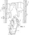
- Fig. 3 shows the actuator 36 being removed from the linkage 14 once that clip 52 has been removed.
- the linkage 14 clears the actuator 36, so the actuator 36 may be removed without dis-assembly of any other components within the active grille shutter system 12.
- the actuator 36 can be further disassembled as shown in Fig. 4 .
- the shaped male connector 45 of first drive arm 44 slides out of the shaped female connector of the actuator 36.
- the shaped male connector 45' of the second drive arm 48 slides out of the shaped female connector 43' of the actuator 36.
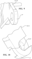
- FIG. 9 depicts a first fixed arm 26' or second fixed arm 28' having a thickness 27'around an aperture 30', 32' that is lower in profile or thinner when compared to a thickness 27 of the variation shown in Fig. 10 .
- the lower profile provides clearance and packaging advantages for the area of the fixed arms 26', 28'.
- the lower profile presents a manufacturing disadvantage that requires the mold tooling used to form the linkage 14 have action features needed to expel the linkage 14 from the mold.
- the variation shown in Fig. 10 Depicts a fixed arm 26 or second fixed arm 28 having two opposing U shaped curves 29, 3 1 that are allow for the formed link 14 to be removed from the tooling without the need for action in the tooling.
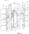
- a serviceable actuation arrangement 100 is shown.
- the serviceable actuation arrangement includes a frame portion 112 of an active grille shutter system.
- the frame portion 112 is depicted as being a center bar of an active grille shutter system, however, it is within the scope of the invention for the frame portion 112 to be a different portion of the frame such as a side bar, top bar, bottom bar or virtually another portion of the frame of the active grille shutter system.
- the frame portion 112 includes an actuator seating section 114 with a base 116 having an aperture 118 through the base 116.
- the opposing side walls 120a, 120b also have outside surfaces 124a, 124b.
- the opposing side walls 120a, 120b have a plurality of vane apertures 126, 126' that extend through from the respective inside surface 122a, 122b to the outside surface 124a, 124b.
- the vane apertures 126, 126' are configured to receive respective post 127a, 127b located on one of a plurality of driven vanes 130a, 130b.
- driven vanes 130a, 130b which are shown as a left side bank of vanes and a right side bank of vanes, with the terms left and right being in relation to the frame portion 112 shown in Fig. 5 .
- Each bank of vanes also includes a drive vane 131a, 131b that is driven by an actuator 144 through various connections that will be discussed in greater detail below.
- Each left bank and right bank includes a link bar 132a, 132b that is connected to the respective drive vane 131a, 131b and driven vanes 130a, 130b.
- the link bar 132a, 132b serves to transfer rotational force from the respective drive vanes 131a, 131b to the driven vanes 130a, 130b.
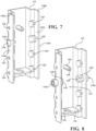
- the opposing side walls 120a, 120b each have a drive aperture 128, 128' with a drive element 134a, 134b rotatably extending through the drive aperture 128, 128'.
- the drive element 134, 134' is formed through the drive aperture 128, 128' in the same mold using a two shot molding process, thereby eliminating the need for an additional assembly step.
- Each drive element 134a, 134b has a first end 136, 136' located within the actuator seating section 114 and a second end 140, 140' of the drive element 134a, 134b is located outside of the frame portion 112.
- the actuator 144 has a housing 146 with drive shafts 148, 148' extending from the housing 146.
- Each of the drive shafts 148, 148' is configured to be driven bi-directionally and are powered by a motor (not shown) located within the housing 146.
- the first end 136, 136' of the drive element has a slot 139, 139' having an open edge 138, 138' which allows for the respective drive shafts 148, 148' to slide into the slot 139, 139' through the open edge 138, 138' so that the drive element 134a, 134b is driven bi-directionally with the actuator 144.
- the actuator 144 housing 146 also includes a seat surface 150 configured to contact against the base 116.
- a connector 152 extends from the seat surface 150 of the actuator housing 146 and provides a port for powering and controlling the movement of the motor of the actuator 144.
- the connector 152 extends through the aperture 118 of the base 116 when the actuator 144 is placed in the actuator seating section 114.
- a locator post 154 located above the base 116.
- the locator post has an aperture 156 that is threaded to receive a fastener 162 that holds the actuator 144 in place.
- the fastener 162 is positioned through an aperture 160 formed on a flange 158 extending from the top surface of the housing 146. While a fastener and threaded connections are shown it is within the scope of this invention for the locator post 154 and flange 158 to have a snap tab or mechanical clip connection.
- FIG. 11 another non-claimed embodiment of a serviceable actuation arrangement 200 is shown with separate drive elements.
- the embodiment shown in Fig. 11 has similar structures to those shown in Figs. 5-8 , therefore the same reference numbers will be used, while different or new structures will be labelled with new reference numbers.
- the serviceable actuation arrangement 200 includes the frame portion 112 of an active grille shutter system. Two opposing side walls 120a, 120b that each have an inside surface 122a, 122b facing the inward to create walls of the actuator seating section 114.
- the opposing side walls 120a, 120b also have outside surfaces 124a, 124b.
- the opposing side walls 120a, 120b have a plurality of vane apertures 126, 126' that extend through from the respective inside surface 122a, 122b to the outside surface 124a, 124b and serve as mounting holes for the driven vanes, just as described above with respect to Figs. 5-8 .
- the opposing side walls 120a, 120b each have a drive aperture 128, 128' configured to receive a drive element 234a, 234b rotatably extending through the drive aperture 128, 128'.
- the drive element 234a, 234b in Fig. 11 differs from the drive element 134a, 134b in Fig. 8 it is a separate piece that is pushed into place through each respective drive aperture 128, 128' rather than being formed in the same mold as the frame portion 112 using a two shot molding process.
- This embodiment also allows the actuator 144 to be connected to the actuator seating section 114 prior to connection of the drive element 234a, 234b.
- the actuator 144 drive shafts 148, 148' are configured to connect with the first end 236, 236' of the drive element 234a, 234b. Near the first end 236, 236' is a slot 239, 239' having an open edge 238, 238' which allows for the respective drive shafts 148, 148' to slide into the slot 239, 239' through the open edge 238, 238' so that the drive element 234a, 234b is driven bi-directionally with the actuator 144.
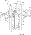
- Fig. 12 is another non-claimed embodiment of a serviceable actuation arrangement 300 having similar structures to those shown in Figs. 5-8 and 11 , therefore the same reference numbers will be used, while different or new structures will be labelled with new reference numbers.
- the serviceable actuation arrangement 300 includes the frame portion 112 of an active grille shutter system. Two opposing side walls 120a, 120b that each have an inside surface 122a, 122b facing the inward to create walls of the actuator seating section 114. The opposing side walls 120a, 120b also have outside surfaces 124a, 124b.
- the opposing side walls 120a, 120b have a plurality of vane apertures 126, 126' that extend through from the respective inside surface 122a, 122b to the outside surface 124a, 124b and serve as mounting holes for the driven vanes, just as described above with respect to Figs. 5-8 .
- the opposing side walls 120a, 120b each have a drive aperture 128, 128' configured to receive a drive element 334a, 334b rotatably extending through the drive aperture 128, 128'.
- the drive element 334a, 334b in Fig. 12 differs from the drive element 234a, 234b in Fig. 11 in that they are integrated with a drive vane 331a, 331 b rather than being a separate piece.
- the integration of the drive vane 331a, 331 b is accomplished in many ways such as injection molding, welding or using adhesives.
- the actuator 144 drive shafts 148, 148' are configured to connect with the first end 336, 336' of the drive element 334a, 334b. Near the first end 336, 336' is a slot 339, 339' having an open edge 338, 338' which allows for the respective drive shafts 148, 148' to slide into the slot 339, 339' through the open edge 338, 338' so that the drive element 334a, 334b is driven bi-directionally with the actuator 144.
Landscapes
- Engineering & Computer Science (AREA)
- Chemical & Material Sciences (AREA)
- Combustion & Propulsion (AREA)
- Mechanical Engineering (AREA)
- Transportation (AREA)
- Structural Engineering (AREA)
- General Engineering & Computer Science (AREA)
- Architecture (AREA)
- Civil Engineering (AREA)
- Cooling, Air Intake And Gas Exhaust, And Fuel Tank Arrangements In Propulsion Units (AREA)
- Specific Sealing Or Ventilating Devices For Doors And Windows (AREA)
Description
- The present invention relates to an improved grille shutter linkage, to allow servicing the actuator without dismantling the full active grille shutter assembly.
- Current active grille shutter systems use an actuator which is directly connected to the vane linkage and integrated into the frame in such a way that it is very difficult to service the actuator if repair is needed. There is a need to design an improved grille shutter linkage to allow servicing the actuator without dismantling the full active grille shutter assembly.
- This invention changes the way the linkage works, from a direct-driven vane, or vanes, to an indirectly-driven linkage, which allows the actuator to de-couple from the vanes by means of a simple clip assembly.
WO 2016/087567 A1 discloses a device for regulating an airstream to a radiator device of a vehicle, wherein the airstream is guidable through at least one opening to the radiator device, with at least two cover elements for at least partially closing the opening in at least a closed position and a drive for moving the cover elements between the closed position and an open position for the at least partial release of the opening, with a driver being provided for the transfer of a movement of the drive to the cover elements, wherein the cover elements are arranged angled towards one another. - The present invention relates to a serviceable actuation arrangement for an active grille shutter system with the features of claims 1 and 3, respectively.
- The arrangement includes a linkage having two vertical link arms spaced apart by a bridge. Each of the two vertical link arms has a plurality of vane connection posts. Connected to the bridge is an actuator that has a first drive arm with a pivot aperture position between the actuator and the bridge. There is also a second drive arm with a pivot aperture position between the actuator in the bridge.
- In order to secure the actuator to the linkage there is provided a connector clip. The connector clip includes a first pivot post that extends through the bridge and the pivot aperture of the first drive arm and a second pivot post extending through the bridge and the pivot aperture of the second drive arm. The connector clip when attached allows the first drive arm and second drive arm to move the linkage through the connection at the bridge, which is secured by the connector clip. If removing the actuator is needed the connector clip allows for the fast disconnection of the actuator by removing the first pivot post and the second pivot post from their respective pivot apertures of the first drive arm and second drive arm. This then allows the actuator to be removed from the arrangement and serviced, without having to disassemble the vanes from the linkage.
- The present invention will become more fully understood from the detailed description and the accompanying drawings, wherein:
-
Fig. 1 is an enlarged partial rear view of a serviceable actuator arrangement according to a first embodiment of the present invention. -
Fig. 2 is an enlarged partial rear view of a serviceable actuator arrangement according to the first embodiment of the present invention with the clip member partially released. -
Fig. 3 is an enlarged partial rear view of a serviceable actuator arrangement with the clip member removed and the actuator disconnected according to the first embodiment of the present invention. -
Fig. 4 is an exploded view of the actuator and drive arms according to the first embodiment of the present invention. -
Fig. 5 is an enlarged partial rear view of a serviceable actuator arrangement according to a non-claimed embodiment. -
Fig. 6 is an enlarged partial rear view of a serviceable actuator arrangement with the fastener removed and the actuator being in the process of being removed according to the non-claimed embodiment. -
Fig. 7 is an enlarged view of the frame portion of the actuator arrangement with the actuator removed the non-claimed embodiment. -
Fig. 8 is an enlarged view of the frame portion and drive elements of the actuator arrangement with the actuator removed according to the non-claimed embodiment. -
Fig. 9 is an enlarged view of a low profile aperture variation of the first or second fixed arm according to the invention. -
Fig. 10 is an enlarged view of a double U shaped curved aperture variation of the first or second fixed arm according to the invention. -
Fig. 11 is another non-claimed embodiment. -
Fig. 12 is another non-claimed embodiment. - Referring to
Figs. 1-4 , the present invention is directed to aserviceable actuation arrangement 10 for an active grille shutter system 12. Theserviceable actuation arrangement 10 includes a linkage with 14 having vertical link arms 16, 18 spaced apart by abridge 20. Thebridge 20 has a clearance opening 22 defined by acurved surface 24 of thebridge 20. Theclearance opening 22 includes a first fixedarm 26 defining a first side of the clearance opening 22 and a second fixedarm 28 defining a second side of the clearance opening 22. The firstfixed arm 26 and the second fixedarm 28 each have anaperture - The two vertical link arms 16, 18 of the
linkage 14 include a plurality ofvane connection posts 34, 34' that connect to apertures 33, 33' onvanes 35a, 35, which are shown as two banks of vanes with a left bank ofvanes 35a and a right bank ofvales 35b. Thevane connection posts 34, 34' can be round protrusions or any type of protrusion capable of sliding into and connecting to a vane member in a manner that allows rotation of the vanes 35 about theplurality connection posts 34, 34'. Also depending on the application apertures are formed on the two vertical link arms and posts are formed on the vanes that connect to the apertures on the vertical link arms. Theserviceable actuation arrangement 10 also includes anactuator 36 positioned between the first fixedarm 26 and the second fixedarm 28, within the clearance opening 22. Theactuator 36 includes afirst drive connection 38 and asecond drive connection 40, which are apertures through ahousing 42 of theactuator 36 that provide access to a rotational force transmitting element. An example is a rotational force element is a hexagonal rotating gear coupled to a motor and located within thefirst drive connection 38 and thesecond drive connection 40. - The
serviceable actuation arrangement 10 also includes afirst drive arm 44 position between theactuator 36 and the first fixedarm 26. Thefirst drive arm 44 is rotatably connected to thefirst drive connection 38 and the firstremovable arm 44 also has apivot aperture 46 that aligns with theaperture 30 of the first fixedarm 26. There is also asecond drive arm 48 positioned between theactuator 36 and the second fixedarm 28. Thesecond drive arm 48 is rotatably connected to thesecond drive connection 40 of theactuator 36. The secondremovable arm 48 also has apivot aperture 50 that aligns with theaperture 32 of the second fixedarm 28. - The
serviceable actuation arrangement 10 further includes a clip 52 having apivot rod 54 connected to thebridge 20 of thelinkage 14. The connection between the clip 52 andbridge 20 of thelinkage 14 is asnap fit connection 53 that allows for rotation of thepivot rod 54 of the clip 52 with respect to thebridge 20. The clip 52 includes two parallel arced bows that include a first parallelarced bow 64 and a second parallel arced bow 66, that both extend in parallel to each other from opposing ends of thepivot rod 54. Afirst pivot post 56 extends from the end of the first parallelarced bow 64 toward the second parallel arced bow 66. Thefirst pivot post 56 pivotally extends through both theaperture 30 of the first fixedarm 26 and thepivot aperture 46 of thefirst drive arm 44. There is also asecond pivot post 58 that extends from the second parallel arced bow 66. Thesecond pivot post 58 is pivotally extending through both theaperture 32 of the second fixedarm 28 and thepivot aperture 50 of thesecond drive arm 48 toward the first parallelarced bow 64. - According to the present invention the
vanes linkage 14, which is not connected, directly to theactuator 36. Thelinkage 14 is connected to theactuator 36 via connector clip 52, thefirst drive arm 44 and thesecond drive arm 48, which can be disassembled to allow theactuator 36 to be removed without having to disassemble or disconnector vanes from thelinkage 14. -
Figs. 1-4 depict how theactuator 36 is removed. InFig. 1 theactuator 36 is connected to thelinkage 14 and held in place by the clip 52 which prevented from rotating by thepivot rod 54 being held in place by asnap fit connection 53 formed on thebridge 20. Also shown are retainer fingers 60, 62 that extend from the first fixedarm 26 and second fixedarm 28 and also assist in securing the clip 52 by pressing the two parallelarced bows 64, 66 inward. The retainer fingers 60, 62 are an optional features and are not necessary for all embodiments of the invention. InFig. 2 thepivot rod 54 has been released from the snap fit connection 52 and the two parallelarced bows 64, 66 have been released from the retainer fingers 60, 62; allowing the clip 52 to rotate downward relative toFig. 2 . When the clip 52 has been released, the parallelarced bows 64, 66 can be flexed outward from each other to pull thefirst pivot post 56 andsecond pivot post 58 out of theapertures arm 26 and second fixedarm 28, as well as therespective pivot apertures first drive arm 44 andsecond drive arm 48.Fig. 3 shows theactuator 36 being removed from thelinkage 14 once that clip 52 has been removed. Thelinkage 14 clears theactuator 36, so the actuator 36 may be removed without dis-assembly of any other components within the active grille shutter system 12. Theactuator 36 can be further disassembled as shown inFig. 4 . The shapedmale connector 45 offirst drive arm 44 slides out of the shaped female connector of theactuator 36. Likewise the shaped male connector 45' of thesecond drive arm 48 slides out of the shaped female connector 43' of theactuator 36. - Referring now to
Figs. 9 and 10 two additional variations of the first fixed arm or second fixedarm 28 are shown.Fig. 9 depicts a first fixed arm 26' or second fixed arm 28' having a thickness 27'around an aperture 30', 32' that is lower in profile or thinner when compared to athickness 27 of the variation shown inFig. 10 . The lower profile provides clearance and packaging advantages for the area of the fixed arms 26', 28'. However, the lower profile presents a manufacturing disadvantage that requires the mold tooling used to form thelinkage 14 have action features needed to expel thelinkage 14 from the mold. The variation shown inFig. 10 . Depicts a fixedarm 26 or second fixedarm 28 having two opposing U shaped curves 29, 3 1 that are allow for the formedlink 14 to be removed from the tooling without the need for action in the tooling. - In
Figs. 5-8 a non-claimed embodiment aserviceable actuation arrangement 100 is shown. The serviceable actuation arrangement includes aframe portion 112 of an active grille shutter system. Theframe portion 112 is depicted as being a center bar of an active grille shutter system, however, it is within the scope of the invention for theframe portion 112 to be a different portion of the frame such as a side bar, top bar, bottom bar or virtually another portion of the frame of the active grille shutter system. Theframe portion 112 includes anactuator seating section 114 with a base 116 having anaperture 118 through thebase 116. There are also two opposingside walls inside surface actuator seating section 114. The opposingside walls outside surfaces side walls vane apertures 126, 126' that extend through from the respective insidesurface outside surface respective post vanes vanes frame portion 112 shown inFig. 5 . While six driven vanes are shown it is within the scope of this invention for a greater or lesser number of driven vanes to be present depending on the needs of a particular application. Each bank of vanes also includes a drive vane 131a, 131b that is driven by anactuator 144 through various connections that will be discussed in greater detail below. Each left bank and right bank includes alink bar 132a, 132b that is connected to the respective drive vane 131a, 131b and drivenvanes link bar 132a, 132b serves to transfer rotational force from the respective drive vanes 131a, 131b to the drivenvanes - The opposing
side walls drive aperture 128, 128' with adrive element drive aperture 128, 128'. In the present embodiment of the invention the drive element 134, 134' is formed through thedrive aperture 128, 128' in the same mold using a two shot molding process, thereby eliminating the need for an additional assembly step. Eachdrive element first end 136, 136' located within theactuator seating section 114 and asecond end 140, 140' of thedrive element frame portion 112. - The
actuator 144 has ahousing 146 withdrive shafts 148, 148' extending from thehousing 146. Each of thedrive shafts 148, 148' is configured to be driven bi-directionally and are powered by a motor (not shown) located within thehousing 146. Thefirst end 136, 136' of the drive element has aslot 139, 139' having anopen edge 138, 138' which allows for therespective drive shafts 148, 148' to slide into theslot 139, 139' through theopen edge 138, 138' so that thedrive element actuator 144. - The
actuator 144housing 146 also includes aseat surface 150 configured to contact against thebase 116. Aconnector 152 extends from theseat surface 150 of theactuator housing 146 and provides a port for powering and controlling the movement of the motor of theactuator 144. Theconnector 152 extends through theaperture 118 of the base 116 when theactuator 144 is placed in theactuator seating section 114. - In order to align the
drive shafts 148, 148' with thedrive element locator post 154 located above thebase 116. The locator post has anaperture 156 that is threaded to receive afastener 162 that holds theactuator 144 in place. Thefastener 162 is positioned through anaperture 160 formed on aflange 158 extending from the top surface of thehousing 146. While a fastener and threaded connections are shown it is within the scope of this invention for thelocator post 154 andflange 158 to have a snap tab or mechanical clip connection. - In
Fig. 11 , another non-claimed embodiment of aserviceable actuation arrangement 200 is shown with separate drive elements. The embodiment shown inFig. 11 has similar structures to those shown inFigs. 5-8 , therefore the same reference numbers will be used, while different or new structures will be labelled with new reference numbers. Theserviceable actuation arrangement 200 includes theframe portion 112 of an active grille shutter system. Two opposingside walls inside surface actuator seating section 114. The opposingside walls outside surfaces side walls vane apertures 126, 126' that extend through from the respective insidesurface outside surface Figs. 5-8 . - The opposing
side walls drive aperture 128, 128' configured to receive adrive element drive aperture 128, 128'. Thedrive element Fig. 11 differs from thedrive element Fig. 8 it is a separate piece that is pushed into place through eachrespective drive aperture 128, 128' rather than being formed in the same mold as theframe portion 112 using a two shot molding process. This embodiment also allows theactuator 144 to be connected to theactuator seating section 114 prior to connection of thedrive element drive element respective drive aperture 128, 128' afirst end 236, 236' will be located within theactuator seating section 114 and asecond end 140, 140' of thedrive element frame portion 112. - The
actuator 144drive shafts 148, 148' are configured to connect with thefirst end 236, 236' of thedrive element first end 236, 236' is aslot 239, 239' having anopen edge 238, 238' which allows for therespective drive shafts 148, 148' to slide into theslot 239, 239' through theopen edge 238, 238' so that thedrive element actuator 144. -
Fig. 12 is another non-claimed embodiment of aserviceable actuation arrangement 300 having similar structures to those shown inFigs. 5-8 and11 , therefore the same reference numbers will be used, while different or new structures will be labelled with new reference numbers. Theserviceable actuation arrangement 300 includes theframe portion 112 of an active grille shutter system. Two opposingside walls inside surface actuator seating section 114. The opposingside walls outside surfaces side walls vane apertures 126, 126' that extend through from the respective insidesurface outside surface Figs. 5-8 . - The opposing
side walls drive aperture 128, 128' configured to receive adrive element drive aperture 128, 128'. Thedrive element Fig. 12 differs from thedrive element Fig. 11 in that they are integrated with adrive vane drive vane drive element respective drive aperture 128, 128' afirst end 336, 336' will be located within theactuator seating section 114 and asecond end 340, 340' of thedrive element frame portion 112. - The
actuator 144drive shafts 148, 148' are configured to connect with thefirst end 336, 336' of thedrive element first end 336, 336' is aslot 339, 339' having anopen edge 338, 338' which allows for therespective drive shafts 148, 148' to slide into theslot 339, 339' through theopen edge 338, 338' so that thedrive element actuator 144.
Claims (9)
- A serviceable actuation arrangement (10) for an active grille shutter system (12) comprising:a linkage (14) having two vertical link arms (16, 18) spaced apart by a bridge (20);an actuator (36) connected to the bridge (20), wherein the actuator (36) moves the linkage (14) between a first position and a second position;a first drive arm (44) with a pivot aperture (46) positioned between the actuator (36) and the bridge (20);a second drive arm (48) with a pivot aperture (50) positioned between the actuator (36) and the bridge (20); anda connector clip (52) having a first pivot post (56) and extending through the bridge (20) and the pivot aperture (46) of the first drive arm (44) and a second pivot post (58) extending through the bridge (20) and the pivot aperture (50) of the second drive arm (48),characterized in that the connector clip (52) has a two parallel arced bows (64, 66) connected together at one end by a pivot rod (54), wherein the pivot rod (54) is rotatably connected to the bridge (20) using a snap-fit tab (53) formed on the bridge (20) and the first pivot post (56) extends from a first one (64) of the two bows and the second pivot post (58) extends from a second one (66) of the two bows, such that the connector is rotatable about the first pivot post (56) and second pivot post (58) when the pivot rod (54) is disconnected from the snap-fit tab (53) of the bridge (20).
- The serviceable actuation arrangement of claim 1, further comprising a clearance opening (22) of the bridge (20) that prevents the bridge from contacting the actuator (36) when the linkage (14) moves.
- A serviceable actuation arrangement for an active grille shutter system (12) comprising:a linkage (14) having two vertical link arms (16, 18) spaced apart by a bridge (20);an actuator (36) connected to the bridge (20), wherein the actuator (36) moves the linkage (14) between a first position and a second position;a first drive arm (44) with a pivot aperture (46) positioned between the actuator (36) and the bridge (20);a second drive arm (48) with a pivot aperture (50) positioned between the actuator (36) and the bridge (20); anda connector clip (52) having a first pivot post (56) extending through the bridge (20) and the pivot aperture (46) of the first drive arm (44) and a second pivot post (58) extending through the bridge (20) and the pivot aperture (50) of the second drive arm (48), andcharacterized by a first fixed arm (26) on the bridge (20) extending toward the actuator (36) and a second fixed arm (28) on the bridge (20) extending toward the actuator (36), wherein the first fixed arm (26) has an aperture (30) and the second fixed arm (28) has an aperture (32) and the first pivot post (56) of the connector clip (52) extends through both the aperture (30) of the first fixed arm (26) and the pivot aperture (46) of the first drive arm (44) and the second pivot post (58) of the connector clip (52) extends through both the aperture (32) of the second fixed arm (28) and the pivot aperture (50) of the second drive arm (48).
- The serviceable actuation arrangement (10) of claim 3, further comprising:a plurality of vane connection posts (34, 34') located on each of the two vertical link arms (16, 18);then actuator (36) positioned between the first fixed arm (26) and the second fixed arm (28), the actuator (36) includes a first drive connection (38) and a second drive connection (40);the first drive arm (44) positioned between the actuator (36) and the first fixed arm (26), wherein the first drive arm (44) is rotatably connected to the first drive connection (38) and the pivot aperture (46) of the first drive arm (44) aligns with the aperture (30) of the first fixed arm (26);the second drive arm (48) positioned between the actuator (36) and the second fixed arm (28), wherein the second drive arm (48) is rotatably connected to the second drive connection (40) and the pivot aperture (50) of the second drive arm (48) aligns with the aperture (32) of the second fixed arm (28); andthe connector clip (52) having a pivot rod (54) pivotally connected to the bridge (20) of the linkage (14).
- The serviceable actuation arrangement of claim 3 -7,- wherein the connector clip (52) has two parallel arced bows (64, 66) connected together at one end by a pivot rod (54), wherein the pivot rod (54) is rotatably connected to the bridge (20) using a snap-fit tab (53) formed on the bridge (20) and the first pivot post (56) extends from a first one (64) of the two bows and the second pivot post (58) extends from a second one (66) of the two bows, such that the connector is rotatable about the first pivot post (56) and second pivot post (58) when the pivot rod (54) is disconnected from the snap-fit tab (53) of the bridge (20).
- The serviceable actuation arrangement of claim 4, further comprising a clearance opening (22) of the bridge (20) that prevents the bridge from contacting the actuator (36) when the linkage (14) moves.
- The serviceable actuation arrangement of claim 3 or 4, further comprising;a first half u-shaped flange (29) on a first side of the first fixed arm (26) and a second half u-shaped flange (31) on a second side of the first fixed arm (26) to assist in the forming of the aperture (30) of the first fixed arm (26), thereby eliminating the need for extra tooling;a first half u-shaped flange on a first side of the second fixed arm and a second half u-shaped flange on a second side of the second fixed arm to assist in the forming of the aperture of the second fixed arm, thereby eliminating the need for extra tooling.
- The serviceable actuation arrangement of claim 1 or 4, further comprisinga plurality of vane pivot posts (34, 34') formed on the two vertical link arms (16, 18);a plurality of vanes (35a, 35b) of an active grille shutter system (12), wherein each one of the plurality of vanes (35a, 35b) is connected to a respective one of the plurality of vane pivot posts (34, 34').
- The serviceable actuation arrangement of claim 3 or 4, further comprising a retainer finger (60) extending from the first fixed arm (26) and the second fixed arm (28) for aligning and retaining the first pivot post (56) and second pivot post (58) through the respective aperture (30) of the first fixed arm (26) and aperture (32) of the second fixed arm (28).
Applications Claiming Priority (2)
| Application Number | Priority Date | Filing Date | Title |
|---|---|---|---|
| US201862680687P | 2018-06-05 | 2018-06-05 | |
| PCT/US2019/029678 WO2019236212A1 (en) | 2018-06-05 | 2019-04-29 | Serviceable actuation system for active grille shutter |
Publications (2)
| Publication Number | Publication Date |
|---|---|
| EP3802187A1 EP3802187A1 (en) | 2021-04-14 |
| EP3802187B1 true EP3802187B1 (en) | 2025-01-08 |
Family
ID=66429713
Family Applications (1)
| Application Number | Title | Priority Date | Filing Date |
|---|---|---|---|
| EP19722492.6A Active EP3802187B1 (en) | 2018-06-05 | 2019-04-29 | Serviceable actuation system for active grille shutter |
Country Status (6)
| Country | Link |
|---|---|
| US (1) | US11230879B2 (en) |
| EP (1) | EP3802187B1 (en) |
| KR (1) | KR102215402B1 (en) |
| CN (1) | CN112351902B (en) |
| CA (1) | CA3102589C (en) |
| WO (1) | WO2019236212A1 (en) |
Families Citing this family (4)
| Publication number | Priority date | Publication date | Assignee | Title |
|---|---|---|---|---|
| EP3802187B1 (en) * | 2018-06-05 | 2025-01-08 | Magna Exteriors Inc. | Serviceable actuation system for active grille shutter |
| WO2021200522A1 (en) * | 2020-04-01 | 2021-10-07 | 株式会社ヴァレオジャパン | Shutter device |
| KR102789603B1 (en) * | 2020-09-11 | 2025-04-01 | 현대모비스 주식회사 | Active Air Flap Apparatus For Vehicle |
| US12583292B2 (en) * | 2023-07-26 | 2026-03-24 | Valeo Systemes Thermiques | Driving vane for an active grille shutter device |
Family Cites Families (21)
| Publication number | Priority date | Publication date | Assignee | Title |
|---|---|---|---|---|
| GB2082520B (en) * | 1980-08-28 | 1983-12-07 | Talbot Motor | Cooling of vehicle engines |
| JP2010223150A (en) * | 2009-03-25 | 2010-10-07 | Aisin Seiki Co Ltd | Movable grill shutter for vehicles |
| US8561739B2 (en) * | 2010-07-13 | 2013-10-22 | Aisin Seiki Kabushiki Kaisha | Movable grille shutter for vehicle |
| KR101272912B1 (en) * | 2010-11-10 | 2013-06-11 | 현대자동차주식회사 | Active air flap apparatus |
| KR101261516B1 (en) * | 2011-04-06 | 2013-05-06 | 토마토에이엔피(주) | A radiator grill comprising air flap |
| CH706456B1 (en) * | 2012-04-30 | 2016-03-15 | Schwanden Kunststoff | Jalousie for placement in front of a radiator. |
| US9573458B2 (en) * | 2012-10-03 | 2017-02-21 | Magna, International Inc. | Spring operated back-up/fail-safe module for active grille shutter systems |
| WO2014205217A1 (en) * | 2013-06-19 | 2014-12-24 | Magna International Inc. | Sealed actuator with internal clutching |
| US9956998B2 (en) * | 2014-06-11 | 2018-05-01 | Magna Exteriors Inc. | Active front deflector |
| EP3002145B1 (en) * | 2014-09-30 | 2017-10-18 | Faltec Company Limited | Vehicle grill shutter, vehicle flap member, and actuator |
| DE102014117816A1 (en) * | 2014-12-03 | 2016-06-09 | Hbpo Gmbh | Optimized air control system for vehicles |
| EP3199395B1 (en) * | 2016-01-29 | 2018-09-19 | Batz, S.Coop. | Shutter device for a front grille of a vehicle |
| DE102016209156A1 (en) * | 2016-05-25 | 2017-11-30 | Magna Exteriors Gmbh | Flap system for the control of vehicle cooling |
| US10960754B2 (en) * | 2016-08-12 | 2021-03-30 | Magna Exteriors, Inc. | Mold assembly for active grille shutter system |
| CA3030990A1 (en) * | 2016-08-12 | 2018-02-15 | Braendon LINDBERG | Active grille, scalable design |
| FR3058367B1 (en) * | 2016-11-09 | 2018-12-07 | Valeo Systemes Thermiques | SHUT OFF DEVICE FOR FRONT PANEL FRONT AIR INTAKE OF MOTOR VEHICLE |
| CN111356566B (en) * | 2017-10-10 | 2022-12-16 | 麦格纳外饰公司 | Hinged Modular Frame Assembled In-Mold with Active Pneumatic System |
| CN107878183A (en) * | 2017-11-29 | 2018-04-06 | 宁波海德欣汽车电器有限公司 | A kind of automotive air intake amount governor motion |
| EP3746324B1 (en) * | 2018-01-30 | 2021-06-16 | Magna Exteriors Inc. | Linkage for improved diagnostics and kinematic assembly |
| FR3078505B1 (en) * | 2018-03-02 | 2020-06-26 | Valeo Systemes Thermiques | SHUTTER UNIT FOR MOTOR VEHICLE SEALING DEVICE |
| EP3802187B1 (en) * | 2018-06-05 | 2025-01-08 | Magna Exteriors Inc. | Serviceable actuation system for active grille shutter |
-
2019
- 2019-04-29 EP EP19722492.6A patent/EP3802187B1/en active Active
- 2019-04-29 US US15/734,853 patent/US11230879B2/en active Active
- 2019-04-29 CA CA3102589A patent/CA3102589C/en active Active
- 2019-04-29 CN CN201980038162.5A patent/CN112351902B/en not_active Expired - Fee Related
- 2019-04-29 WO PCT/US2019/029678 patent/WO2019236212A1/en not_active Ceased
- 2019-04-29 KR KR1020207037904A patent/KR102215402B1/en active Active
Also Published As
| Publication number | Publication date |
|---|---|
| US11230879B2 (en) | 2022-01-25 |
| WO2019236212A1 (en) | 2019-12-12 |
| EP3802187A1 (en) | 2021-04-14 |
| CN112351902B (en) | 2022-02-25 |
| CA3102589C (en) | 2021-03-30 |
| US20210230936A1 (en) | 2021-07-29 |
| CN112351902A (en) | 2021-02-09 |
| KR102215402B1 (en) | 2021-02-10 |
| KR20210009385A (en) | 2021-01-26 |
| CA3102589A1 (en) | 2019-12-12 |
Similar Documents
| Publication | Publication Date | Title |
|---|---|---|
| EP3802187B1 (en) | Serviceable actuation system for active grille shutter | |
| CN109564024B (en) | Expandable design of active grille | |
| US9533565B2 (en) | Active grille shutter assembly | |
| US9139165B2 (en) | Device for attaching a windshield wiper blade on an arm | |
| US9707839B2 (en) | Air inlet for a motor vehicle | |
| CN103476617B (en) | Drive system for multiple movable systems | |
| EP3119635B1 (en) | Hollow vane with structure | |
| US6010113A (en) | Damper with fanning blades | |
| CN104080692B (en) | Assembly of a front frame of a motor vehicle and a support supporting an actuator | |
| CN108602427B (en) | Air Inlet Management System for Motor Vehicle Front Panels | |
| AU2019291608B2 (en) | Hinged valve | |
| US10889179B2 (en) | Shutter grill | |
| JP4044821B2 (en) | Supply / exhaust grill | |
| JP6813686B2 (en) | Ball joint with locking ball socket assembly | |
| JP5840790B2 (en) | Valve for controlling the internal pressure of the aircraft cabin | |
| CN110958955A (en) | Device for closing a motor vehicle air intake and method of making the same | |
| KR101936726B1 (en) | Active Air Flap | |
| CA3010479C (en) | Valve for bypass conduit | |
| US20260103067A1 (en) | Adjustable visible vanes for an adjustable grille shutter system | |
| CN215426589U (en) | Storehouse door structure of transfer pump | |
| CN106917779B (en) | Water discharge pump | |
| US20210016745A1 (en) | Multiple position locking wiper arm connector | |
| US20250011050A1 (en) | Housing | |
| EP3839179B1 (en) | Support assembly of a panic bar device | |
| JPH0960755A (en) | Motor-operated valve |
Legal Events
| Date | Code | Title | Description |
|---|---|---|---|
| STAA | Information on the status of an ep patent application or granted ep patent |
Free format text: STATUS: UNKNOWN |
|
| STAA | Information on the status of an ep patent application or granted ep patent |
Free format text: STATUS: THE INTERNATIONAL PUBLICATION HAS BEEN MADE |
|
| PUAI | Public reference made under article 153(3) epc to a published international application that has entered the european phase |
Free format text: ORIGINAL CODE: 0009012 |
|
| STAA | Information on the status of an ep patent application or granted ep patent |
Free format text: STATUS: REQUEST FOR EXAMINATION WAS MADE |
|
| 17P | Request for examination filed |
Effective date: 20201211 |
|
| AK | Designated contracting states |
Kind code of ref document: A1 Designated state(s): AL AT BE BG CH CY CZ DE DK EE ES FI FR GB GR HR HU IE IS IT LI LT LU LV MC MK MT NL NO PL PT RO RS SE SI SK SM TR |
|
| AX | Request for extension of the european patent |
Extension state: BA ME |
|
| DAV | Request for validation of the european patent (deleted) | ||
| DAX | Request for extension of the european patent (deleted) | ||
| STAA | Information on the status of an ep patent application or granted ep patent |
Free format text: STATUS: EXAMINATION IS IN PROGRESS |
|
| 17Q | First examination report despatched |
Effective date: 20220530 |
|
| P01 | Opt-out of the competence of the unified patent court (upc) registered |
Effective date: 20230517 |
|
| GRAP | Despatch of communication of intention to grant a patent |
Free format text: ORIGINAL CODE: EPIDOSNIGR1 |
|
| STAA | Information on the status of an ep patent application or granted ep patent |
Free format text: STATUS: GRANT OF PATENT IS INTENDED |
|
| INTG | Intention to grant announced |
Effective date: 20240802 |
|
| RAP3 | Party data changed (applicant data changed or rights of an application transferred) |
Owner name: MAGNA EXTERIORS INC. |
|
| GRAS | Grant fee paid |
Free format text: ORIGINAL CODE: EPIDOSNIGR3 |
|
| GRAA | (expected) grant |
Free format text: ORIGINAL CODE: 0009210 |
|
| STAA | Information on the status of an ep patent application or granted ep patent |
Free format text: STATUS: THE PATENT HAS BEEN GRANTED |
|
| AK | Designated contracting states |
Kind code of ref document: B1 Designated state(s): AL AT BE BG CH CY CZ DE DK EE ES FI FR GB GR HR HU IE IS IT LI LT LU LV MC MK MT NL NO PL PT RO RS SE SI SK SM TR |
|
| REG | Reference to a national code |
Ref country code: GB Ref legal event code: FG4D |
|
| REG | Reference to a national code |
Ref country code: CH Ref legal event code: EP |
|
| REG | Reference to a national code |
Ref country code: DE Ref legal event code: R096 Ref document number: 602019064582 Country of ref document: DE |
|
| REG | Reference to a national code |
Ref country code: IE Ref legal event code: FG4D |
|
| REG | Reference to a national code |
Ref country code: LT Ref legal event code: MG9D |
|
| REG | Reference to a national code |
Ref country code: NL Ref legal event code: MP Effective date: 20250108 |
|
| REG | Reference to a national code |
Ref country code: AT Ref legal event code: MK05 Ref document number: 1758116 Country of ref document: AT Kind code of ref document: T Effective date: 20250108 |
|
| PG25 | Lapsed in a contracting state [announced via postgrant information from national office to epo] |
Ref country code: NL Free format text: LAPSE BECAUSE OF FAILURE TO SUBMIT A TRANSLATION OF THE DESCRIPTION OR TO PAY THE FEE WITHIN THE PRESCRIBED TIME-LIMIT Effective date: 20250108 |
|
| PG25 | Lapsed in a contracting state [announced via postgrant information from national office to epo] |
Ref country code: RS Free format text: LAPSE BECAUSE OF FAILURE TO SUBMIT A TRANSLATION OF THE DESCRIPTION OR TO PAY THE FEE WITHIN THE PRESCRIBED TIME-LIMIT Effective date: 20250408 |
|
| PG25 | Lapsed in a contracting state [announced via postgrant information from national office to epo] |
Ref country code: FI Free format text: LAPSE BECAUSE OF FAILURE TO SUBMIT A TRANSLATION OF THE DESCRIPTION OR TO PAY THE FEE WITHIN THE PRESCRIBED TIME-LIMIT Effective date: 20250108 |
|
| PG25 | Lapsed in a contracting state [announced via postgrant information from national office to epo] |
Ref country code: PL Free format text: LAPSE BECAUSE OF FAILURE TO SUBMIT A TRANSLATION OF THE DESCRIPTION OR TO PAY THE FEE WITHIN THE PRESCRIBED TIME-LIMIT Effective date: 20250108 |
|
| PG25 | Lapsed in a contracting state [announced via postgrant information from national office to epo] |
Ref country code: ES Free format text: LAPSE BECAUSE OF FAILURE TO SUBMIT A TRANSLATION OF THE DESCRIPTION OR TO PAY THE FEE WITHIN THE PRESCRIBED TIME-LIMIT Effective date: 20250108 |
|
| PG25 | Lapsed in a contracting state [announced via postgrant information from national office to epo] |
Ref country code: NO Free format text: LAPSE BECAUSE OF FAILURE TO SUBMIT A TRANSLATION OF THE DESCRIPTION OR TO PAY THE FEE WITHIN THE PRESCRIBED TIME-LIMIT Effective date: 20250408 Ref country code: IS Free format text: LAPSE BECAUSE OF FAILURE TO SUBMIT A TRANSLATION OF THE DESCRIPTION OR TO PAY THE FEE WITHIN THE PRESCRIBED TIME-LIMIT Effective date: 20250508 |
|
| PG25 | Lapsed in a contracting state [announced via postgrant information from national office to epo] |
Ref country code: HR Free format text: LAPSE BECAUSE OF FAILURE TO SUBMIT A TRANSLATION OF THE DESCRIPTION OR TO PAY THE FEE WITHIN THE PRESCRIBED TIME-LIMIT Effective date: 20250108 |
|
| PG25 | Lapsed in a contracting state [announced via postgrant information from national office to epo] |
Ref country code: LV Free format text: LAPSE BECAUSE OF FAILURE TO SUBMIT A TRANSLATION OF THE DESCRIPTION OR TO PAY THE FEE WITHIN THE PRESCRIBED TIME-LIMIT Effective date: 20250108 Ref country code: PT Free format text: LAPSE BECAUSE OF FAILURE TO SUBMIT A TRANSLATION OF THE DESCRIPTION OR TO PAY THE FEE WITHIN THE PRESCRIBED TIME-LIMIT Effective date: 20250508 |
|
| PG25 | Lapsed in a contracting state [announced via postgrant information from national office to epo] |
Ref country code: GR Free format text: LAPSE BECAUSE OF FAILURE TO SUBMIT A TRANSLATION OF THE DESCRIPTION OR TO PAY THE FEE WITHIN THE PRESCRIBED TIME-LIMIT Effective date: 20250409 Ref country code: BG Free format text: LAPSE BECAUSE OF FAILURE TO SUBMIT A TRANSLATION OF THE DESCRIPTION OR TO PAY THE FEE WITHIN THE PRESCRIBED TIME-LIMIT Effective date: 20250108 |
|
| PG25 | Lapsed in a contracting state [announced via postgrant information from national office to epo] |
Ref country code: AT Free format text: LAPSE BECAUSE OF FAILURE TO SUBMIT A TRANSLATION OF THE DESCRIPTION OR TO PAY THE FEE WITHIN THE PRESCRIBED TIME-LIMIT Effective date: 20250108 |
|
| PG25 | Lapsed in a contracting state [announced via postgrant information from national office to epo] |
Ref country code: SE Free format text: LAPSE BECAUSE OF FAILURE TO SUBMIT A TRANSLATION OF THE DESCRIPTION OR TO PAY THE FEE WITHIN THE PRESCRIBED TIME-LIMIT Effective date: 20250108 |
|
| PG25 | Lapsed in a contracting state [announced via postgrant information from national office to epo] |
Ref country code: SM Free format text: LAPSE BECAUSE OF FAILURE TO SUBMIT A TRANSLATION OF THE DESCRIPTION OR TO PAY THE FEE WITHIN THE PRESCRIBED TIME-LIMIT Effective date: 20250108 |
|
| REG | Reference to a national code |
Ref country code: DE Ref legal event code: R097 Ref document number: 602019064582 Country of ref document: DE |
|
| PG25 | Lapsed in a contracting state [announced via postgrant information from national office to epo] |
Ref country code: DK Free format text: LAPSE BECAUSE OF FAILURE TO SUBMIT A TRANSLATION OF THE DESCRIPTION OR TO PAY THE FEE WITHIN THE PRESCRIBED TIME-LIMIT Effective date: 20250108 |
|
| PG25 | Lapsed in a contracting state [announced via postgrant information from national office to epo] |
Ref country code: EE Free format text: LAPSE BECAUSE OF FAILURE TO SUBMIT A TRANSLATION OF THE DESCRIPTION OR TO PAY THE FEE WITHIN THE PRESCRIBED TIME-LIMIT Effective date: 20250108 Ref country code: CZ Free format text: LAPSE BECAUSE OF FAILURE TO SUBMIT A TRANSLATION OF THE DESCRIPTION OR TO PAY THE FEE WITHIN THE PRESCRIBED TIME-LIMIT Effective date: 20250108 |
|
| PG25 | Lapsed in a contracting state [announced via postgrant information from national office to epo] |
Ref country code: RO Free format text: LAPSE BECAUSE OF FAILURE TO SUBMIT A TRANSLATION OF THE DESCRIPTION OR TO PAY THE FEE WITHIN THE PRESCRIBED TIME-LIMIT Effective date: 20250108 |
|
| PG25 | Lapsed in a contracting state [announced via postgrant information from national office to epo] |
Ref country code: SK Free format text: LAPSE BECAUSE OF FAILURE TO SUBMIT A TRANSLATION OF THE DESCRIPTION OR TO PAY THE FEE WITHIN THE PRESCRIBED TIME-LIMIT Effective date: 20250108 |
|
| REG | Reference to a national code |
Ref country code: DE Ref legal event code: R119 Ref document number: 602019064582 Country of ref document: DE |
|
| PLBE | No opposition filed within time limit |
Free format text: ORIGINAL CODE: 0009261 |
|
| STAA | Information on the status of an ep patent application or granted ep patent |
Free format text: STATUS: NO OPPOSITION FILED WITHIN TIME LIMIT |
|
| REG | Reference to a national code |
Ref country code: CH Ref legal event code: L10 Free format text: ST27 STATUS EVENT CODE: U-0-0-L10-L00 (AS PROVIDED BY THE NATIONAL OFFICE) Effective date: 20251119 |
|
| REG | Reference to a national code |
Ref country code: CH Ref legal event code: H13 Free format text: ST27 STATUS EVENT CODE: U-0-0-H10-H13 (AS PROVIDED BY THE NATIONAL OFFICE) Effective date: 20251125 |
|
| PG25 | Lapsed in a contracting state [announced via postgrant information from national office to epo] |
Ref country code: LU Free format text: LAPSE BECAUSE OF NON-PAYMENT OF DUE FEES Effective date: 20250429 |
|
| 26N | No opposition filed |
Effective date: 20251009 |
|
| PG25 | Lapsed in a contracting state [announced via postgrant information from national office to epo] |
Ref country code: MC Free format text: LAPSE BECAUSE OF FAILURE TO SUBMIT A TRANSLATION OF THE DESCRIPTION OR TO PAY THE FEE WITHIN THE PRESCRIBED TIME-LIMIT Effective date: 20250108 |
|
| GBPC | Gb: european patent ceased through non-payment of renewal fee |
Effective date: 20250429 |
|
| REG | Reference to a national code |
Ref country code: BE Ref legal event code: MM Effective date: 20250430 |
|
| PG25 | Lapsed in a contracting state [announced via postgrant information from national office to epo] |
Ref country code: DE Free format text: LAPSE BECAUSE OF NON-PAYMENT OF DUE FEES Effective date: 20251104 |
|
| PG25 | Lapsed in a contracting state [announced via postgrant information from national office to epo] |
Ref country code: GB Free format text: LAPSE BECAUSE OF NON-PAYMENT OF DUE FEES Effective date: 20250429 |
|
| PG25 | Lapsed in a contracting state [announced via postgrant information from national office to epo] |
Ref country code: FR Free format text: LAPSE BECAUSE OF NON-PAYMENT OF DUE FEES Effective date: 20250430 |
|
| PG25 | Lapsed in a contracting state [announced via postgrant information from national office to epo] |
Ref country code: BE Free format text: LAPSE BECAUSE OF NON-PAYMENT OF DUE FEES Effective date: 20250430 |
|
| PG25 | Lapsed in a contracting state [announced via postgrant information from national office to epo] |
Ref country code: CH Free format text: LAPSE BECAUSE OF NON-PAYMENT OF DUE FEES Effective date: 20250430 |
|
| PG25 | Lapsed in a contracting state [announced via postgrant information from national office to epo] |
Ref country code: IT Free format text: LAPSE BECAUSE OF FAILURE TO SUBMIT A TRANSLATION OF THE DESCRIPTION OR TO PAY THE FEE WITHIN THE PRESCRIBED TIME-LIMIT Effective date: 20250108 |
|
| PG25 | Lapsed in a contracting state [announced via postgrant information from national office to epo] |
Ref country code: IE Free format text: LAPSE BECAUSE OF NON-PAYMENT OF DUE FEES Effective date: 20250429 |