EP3801809B1 - Microfluidic filter device and method for dissociation of tissue and cell aggregates and enrichment of single cells - Google Patents
Microfluidic filter device and method for dissociation of tissue and cell aggregates and enrichment of single cells Download PDFInfo
- Publication number
- EP3801809B1 EP3801809B1 EP19811784.8A EP19811784A EP3801809B1 EP 3801809 B1 EP3801809 B1 EP 3801809B1 EP 19811784 A EP19811784 A EP 19811784A EP 3801809 B1 EP3801809 B1 EP 3801809B1
- Authority
- EP
- European Patent Office
- Prior art keywords
- microfluidic
- tissue
- filter membrane
- filtration device
- membrane
- Prior art date
- Legal status (The legal status is an assumption and is not a legal conclusion. Google has not performed a legal analysis and makes no representation as to the accuracy of the status listed.)
- Active
Links
Images





Classifications
-
- F—MECHANICAL ENGINEERING; LIGHTING; HEATING; WEAPONS; BLASTING
- F04—POSITIVE - DISPLACEMENT MACHINES FOR LIQUIDS; PUMPS FOR LIQUIDS OR ELASTIC FLUIDS
- F04B—POSITIVE-DISPLACEMENT MACHINES FOR LIQUIDS; PUMPS
- F04B43/00—Machines, pumps, or pumping installations having flexible working members
- F04B43/02—Machines, pumps, or pumping installations having flexible working members having plate-like flexible members, e.g. diaphragms
- F04B43/04—Pumps having electric drive
-
- B—PERFORMING OPERATIONS; TRANSPORTING
- B01—PHYSICAL OR CHEMICAL PROCESSES OR APPARATUS IN GENERAL
- B01D—SEPARATION
- B01D63/00—Apparatus in general for separation processes using semi-permeable membranes
- B01D63/005—Microfluidic devices
-
- B—PERFORMING OPERATIONS; TRANSPORTING
- B01—PHYSICAL OR CHEMICAL PROCESSES OR APPARATUS IN GENERAL
- B01D—SEPARATION
- B01D63/00—Apparatus in general for separation processes using semi-permeable membranes
- B01D63/08—Flat membrane modules
- B01D63/088—Microfluidic devices comprising semi-permeable flat membranes
-
- B—PERFORMING OPERATIONS; TRANSPORTING
- B01—PHYSICAL OR CHEMICAL PROCESSES OR APPARATUS IN GENERAL
- B01D—SEPARATION
- B01D69/00—Semi-permeable membranes for separation processes or apparatus characterised by their form, structure or properties; Manufacturing processes specially adapted therefor
- B01D69/02—Semi-permeable membranes for separation processes or apparatus characterised by their form, structure or properties; Manufacturing processes specially adapted therefor characterised by their properties
-
- B—PERFORMING OPERATIONS; TRANSPORTING
- B01—PHYSICAL OR CHEMICAL PROCESSES OR APPARATUS IN GENERAL
- B01L—CHEMICAL OR PHYSICAL LABORATORY APPARATUS FOR GENERAL USE
- B01L3/00—Containers or dishes for laboratory use, e.g. laboratory glassware; Droppers
- B01L3/50—Containers for the purpose of retaining a material to be analysed, e.g. test tubes
- B01L3/502—Containers for the purpose of retaining a material to be analysed, e.g. test tubes with fluid transport, e.g. in multi-compartment structures
- B01L3/5027—Containers for the purpose of retaining a material to be analysed, e.g. test tubes with fluid transport, e.g. in multi-compartment structures by integrated microfluidic structures, i.e. dimensions of channels and chambers are such that surface tension forces are important, e.g. lab-on-a-chip
- B01L3/502753—Containers for the purpose of retaining a material to be analysed, e.g. test tubes with fluid transport, e.g. in multi-compartment structures by integrated microfluidic structures, i.e. dimensions of channels and chambers are such that surface tension forces are important, e.g. lab-on-a-chip characterised by bulk separation arrangements on lab-on-a-chip devices, e.g. for filtration or centrifugation
-
- B—PERFORMING OPERATIONS; TRANSPORTING
- B01—PHYSICAL OR CHEMICAL PROCESSES OR APPARATUS IN GENERAL
- B01L—CHEMICAL OR PHYSICAL LABORATORY APPARATUS FOR GENERAL USE
- B01L3/00—Containers or dishes for laboratory use, e.g. laboratory glassware; Droppers
- B01L3/50—Containers for the purpose of retaining a material to be analysed, e.g. test tubes
- B01L3/502—Containers for the purpose of retaining a material to be analysed, e.g. test tubes with fluid transport, e.g. in multi-compartment structures
- B01L3/5027—Containers for the purpose of retaining a material to be analysed, e.g. test tubes with fluid transport, e.g. in multi-compartment structures by integrated microfluidic structures, i.e. dimensions of channels and chambers are such that surface tension forces are important, e.g. lab-on-a-chip
- B01L3/502761—Containers for the purpose of retaining a material to be analysed, e.g. test tubes with fluid transport, e.g. in multi-compartment structures by integrated microfluidic structures, i.e. dimensions of channels and chambers are such that surface tension forces are important, e.g. lab-on-a-chip specially adapted for handling suspended solids or molecules independently from the bulk fluid flow, e.g. for trapping or sorting beads or physically stretching molecules
-
- C—CHEMISTRY; METALLURGY
- C12—BIOCHEMISTRY; BEER; SPIRITS; WINE; VINEGAR; MICROBIOLOGY; ENZYMOLOGY; MUTATION OR GENETIC ENGINEERING
- C12M—APPARATUS FOR ENZYMOLOGY OR MICROBIOLOGY; APPARATUS FOR CULTURING MICROORGANISMS FOR PRODUCING BIOMASS, FOR GROWING CELLS OR FOR OBTAINING FERMENTATION OR METABOLIC PRODUCTS, i.e. BIOREACTORS OR FERMENTERS
- C12M23/00—Constructional details, e.g. recesses, hinges
- C12M23/02—Form or structure of the vessel
- C12M23/16—Microfluidic devices; Capillary tubes
-
- C—CHEMISTRY; METALLURGY
- C12—BIOCHEMISTRY; BEER; SPIRITS; WINE; VINEGAR; MICROBIOLOGY; ENZYMOLOGY; MUTATION OR GENETIC ENGINEERING
- C12M—APPARATUS FOR ENZYMOLOGY OR MICROBIOLOGY; APPARATUS FOR CULTURING MICROORGANISMS FOR PRODUCING BIOMASS, FOR GROWING CELLS OR FOR OBTAINING FERMENTATION OR METABOLIC PRODUCTS, i.e. BIOREACTORS OR FERMENTERS
- C12M29/00—Means for introduction, extraction or recirculation of materials, e.g. pumps
- C12M29/04—Filters; Permeable or porous membranes or plates, e.g. dialysis
-
- C—CHEMISTRY; METALLURGY
- C12—BIOCHEMISTRY; BEER; SPIRITS; WINE; VINEGAR; MICROBIOLOGY; ENZYMOLOGY; MUTATION OR GENETIC ENGINEERING
- C12M—APPARATUS FOR ENZYMOLOGY OR MICROBIOLOGY; APPARATUS FOR CULTURING MICROORGANISMS FOR PRODUCING BIOMASS, FOR GROWING CELLS OR FOR OBTAINING FERMENTATION OR METABOLIC PRODUCTS, i.e. BIOREACTORS OR FERMENTERS
- C12M45/00—Means for pre-treatment of biological substances
- C12M45/02—Means for pre-treatment of biological substances by mechanical forces; Stirring; Trituration; Comminuting
-
- C—CHEMISTRY; METALLURGY
- C12—BIOCHEMISTRY; BEER; SPIRITS; WINE; VINEGAR; MICROBIOLOGY; ENZYMOLOGY; MUTATION OR GENETIC ENGINEERING
- C12M—APPARATUS FOR ENZYMOLOGY OR MICROBIOLOGY; APPARATUS FOR CULTURING MICROORGANISMS FOR PRODUCING BIOMASS, FOR GROWING CELLS OR FOR OBTAINING FERMENTATION OR METABOLIC PRODUCTS, i.e. BIOREACTORS OR FERMENTERS
- C12M47/00—Means for after-treatment of the produced biomass or of the fermentation or metabolic products, e.g. storage of biomass
- C12M47/04—Cell isolation or sorting
-
- G—PHYSICS
- G01—MEASURING; TESTING
- G01N—INVESTIGATING OR ANALYSING MATERIALS BY DETERMINING THEIR CHEMICAL OR PHYSICAL PROPERTIES
- G01N1/00—Sampling; Preparing specimens for investigation
- G01N1/28—Preparing specimens for investigation including physical details of (bio-)chemical methods covered elsewhere, e.g. G01N33/50, C12Q
- G01N1/40—Concentrating samples
- G01N1/4077—Concentrating samples by other techniques involving separation of suspended solids
-
- B—PERFORMING OPERATIONS; TRANSPORTING
- B01—PHYSICAL OR CHEMICAL PROCESSES OR APPARATUS IN GENERAL
- B01D—SEPARATION
- B01D2319/00—Membrane assemblies within one housing
- B01D2319/02—Elements in series
- B01D2319/025—Permeate series
-
- B—PERFORMING OPERATIONS; TRANSPORTING
- B01—PHYSICAL OR CHEMICAL PROCESSES OR APPARATUS IN GENERAL
- B01D—SEPARATION
- B01D2325/00—Details relating to properties of membranes
- B01D2325/02—Details relating to pores or porosity of the membranes
- B01D2325/0283—Pore size
-
- B—PERFORMING OPERATIONS; TRANSPORTING
- B01—PHYSICAL OR CHEMICAL PROCESSES OR APPARATUS IN GENERAL
- B01L—CHEMICAL OR PHYSICAL LABORATORY APPARATUS FOR GENERAL USE
- B01L2200/00—Solutions for specific problems relating to chemical or physical laboratory apparatus
- B01L2200/02—Adapting objects or devices to another
- B01L2200/026—Fluid interfacing between devices or objects, e.g. connectors, inlet details
- B01L2200/027—Fluid interfacing between devices or objects, e.g. connectors, inlet details for microfluidic devices
-
- B—PERFORMING OPERATIONS; TRANSPORTING
- B01—PHYSICAL OR CHEMICAL PROCESSES OR APPARATUS IN GENERAL
- B01L—CHEMICAL OR PHYSICAL LABORATORY APPARATUS FOR GENERAL USE
- B01L2200/00—Solutions for specific problems relating to chemical or physical laboratory apparatus
- B01L2200/06—Fluid handling related problems
- B01L2200/0647—Handling flowable solids, e.g. microscopic beads, cells, particles
- B01L2200/0652—Sorting or classification of particles or molecules
-
- B—PERFORMING OPERATIONS; TRANSPORTING
- B01—PHYSICAL OR CHEMICAL PROCESSES OR APPARATUS IN GENERAL
- B01L—CHEMICAL OR PHYSICAL LABORATORY APPARATUS FOR GENERAL USE
- B01L2300/00—Additional constructional details
- B01L2300/06—Auxiliary integrated devices, integrated components
- B01L2300/0681—Filter
-
- B—PERFORMING OPERATIONS; TRANSPORTING
- B01—PHYSICAL OR CHEMICAL PROCESSES OR APPARATUS IN GENERAL
- B01L—CHEMICAL OR PHYSICAL LABORATORY APPARATUS FOR GENERAL USE
- B01L2300/00—Additional constructional details
- B01L2300/08—Geometry, shape and general structure
- B01L2300/0809—Geometry, shape and general structure rectangular shaped
- B01L2300/0816—Cards, e.g. flat sample carriers usually with flow in two horizontal directions
-
- B—PERFORMING OPERATIONS; TRANSPORTING
- B01—PHYSICAL OR CHEMICAL PROCESSES OR APPARATUS IN GENERAL
- B01L—CHEMICAL OR PHYSICAL LABORATORY APPARATUS FOR GENERAL USE
- B01L2300/00—Additional constructional details
- B01L2300/08—Geometry, shape and general structure
- B01L2300/0861—Configuration of multiple channels and/or chambers in a single devices
- B01L2300/0864—Configuration of multiple channels and/or chambers in a single devices comprising only one inlet and multiple receiving wells, e.g. for separation, splitting
-
- G—PHYSICS
- G01—MEASURING; TESTING
- G01N—INVESTIGATING OR ANALYSING MATERIALS BY DETERMINING THEIR CHEMICAL OR PHYSICAL PROPERTIES
- G01N1/00—Sampling; Preparing specimens for investigation
- G01N1/28—Preparing specimens for investigation including physical details of (bio-)chemical methods covered elsewhere, e.g. G01N33/50, C12Q
- G01N1/40—Concentrating samples
- G01N1/4077—Concentrating samples by other techniques involving separation of suspended solids
- G01N2001/4088—Concentrating samples by other techniques involving separation of suspended solids filtration
Definitions
- the technical field generally relates to microfluidic devices and methods for obtaining single cells from tissue fragments and cell aggregates. More particularly, the invention pertains to an inexpensive microfluidic device that simultaneously filters large tissue fragments and dissociates smaller aggregates into single cells, thereby improving single cell yield and purity.
- tissue has been dissociated by mincing into small pieces with a scalpel, digesting with proteolytic enzymes, mechanically dissociating with a pipette and/or vortexing followed by filtering with a cell strainer to remove the remaining aggregates.
- Microfluidic technologies have recently been developed to automate and improve tissue dissociation, including on-chip digestion and disaggregation using sharp surface edges, post arrays, and branching channel networks that generate hydrodynamic fluid jets.
- WO 2018/003476 A1 discloses a cell filtration device comprising an inlet coupled to a first fluidic channel at an upstream location, the first fluidic channel coupled to a first outlet at a downstream location, a filter membrane interposed between the first fluidic channel and a second fluidic channel, wherein the second fluidic channel is in fluidic communication with the first fluidic channel via the filter membrane; and a second outlet coupled to a downstream location of the second fluidic channel.
- the first and second fluidic channels are formed directly in a container and are separated by the filter membrane extending through a whole width of the container. The resulting tangential flow might show limitations and the cell filtration device might be subject to improvements..
- KR 2012 0042531 A discloses a cell collection device comprising a tube having a channel and tube wall to transferring a fluid sample containing target cells; a plurality of filtering holes which are mounted at the channel; a screen filter for collecting the target cells by inducing flow of the target cells into a boundary contacting the tube wall.
- US 2017/0145053 A1 discloses a fluid treatment device for use in tangential flow filtration, comprising a housing unit and a composite material, wherein the composite material comprises: a support member comprising a plurality of pores extending through the support member; and a non-self-supporting macroporous cross-linked gel comprising macropores having an average size of 10 nm to 3000 nm, said macroporous gel being located in the pores of the support member.
- the invention is directed to a microfluidic tissue dissociation and filtration device according to claim 1.
- the first outlet accommodates the passage of fluid and contents that do not pass through the first filter membrane while the second outlet accommodates the passage of fluid and cells or smaller cell aggregates that pass through the first filter membrane.
- the invention is also directed to a method according to claim 13. Further developments are according to dependent claims 14 and 15.
- FIG. 1A illustrates a cross-sectional view of the microfluidic tissue dissociation and filtration device 10 according to one embodiment.
- the microfluidic tissue dissociation and filtration device 10 is formed in one or more substrates or layer 12 as best illustrated in FIGS. 1D, 1E , 1F , 1G, and 1H .
- the substrates or layers 12 may be formed from a polymer or plastic material that contains various features formed therein that are laminated or otherwise bonded together to form the final microfluidic tissue dissociation and filtration device 10 according to one embodiment.
- the various features formed in the substrates or layers 12 include the channels and fluid passageways (described below in more detail) through which fluid flows during operation of the microfluidic tissue dissociation and filtration device 10.
- the microfluidic tissue dissociation and filtration device 10 includes an inlet 14 through which fluid flows into the microfluidic tissue dissociation and filtration device 10.
- the inlet 14 may include a barbed end 40 or the like as illustrated that can be connected to tubing or other conduit that is used to deliver the fluid containing tissue to the microfluidic tissue dissociation and filtration device 10.
- the inlet 14 is fluidically coupled to a first microfluidic channel 16 at an upstream location (arrows indicate the direction of fluid flow).
- the first microfluidic channel 16 is also coupled to a first outlet 18 that is located at a downstream location.
- the first outlet 18 may include a barbed end 40 or the like as illustrated that can be connected to tubing or other conduit that is used to remove fluid containing cells and cell aggregates from the microfluidic tissue dissociation and filtration device 10.
- the first microfluidic channel 16 is at least partially defined in one or more of the substrates or layers 12.
- the surfaces (top, bottom, sides) of the first microfluidic channel 16 may be defined in the one or more of the substrates or layers 12.
- the typical cross-sectional dimension of the first microfluidic channel 16 may include a height within the range of about 200 ⁇ m to about 1 mm and a width within the range of about 1 mm to about 1 cm.
- the length of the first microfluidic channel 16 may vary from a few centimeters and tens or even hundreds of centimeters (e.g., from about 5 cm to about 100 cm in one example). It should be appreciated that these dimensions are illustrative.
- the microfluidic tissue dissociation and filtration device 10 includes a second microfluidic channel 20.
- the second microfluidic channel 20 is, in one embodiment, disposed in a different substrate or layer 12 of the microfluidic tissue dissociation and filtration device 10 as seen in FIGS. 1D, 1E , 1F , 1G, and 1H .
- the second microfluidic channel 20 is located in a different plane than the first microfluidic channel 16.
- the second microfluidic channel 20 may be located in a lower plane than the first microfluidic channel 16.
- the second microfluidic channel 20 may be defined in the one or more of the substrates or layers 12.
- the typical cross-sectional dimension of the second microfluidic channel 20 may include a height within the range of about 200 ⁇ m to about 1 mm and a width within the range of about 1 mm to about 1 cm.
- the length of the second microfluidic channel 20 (from end to end) may vary from a few centimeters and tens or even hundreds of centimeters (e.g., from about 5 cm to about 100 cm in one example). It should be appreciated that these dimensions are illustrative.
- the second microfluidic channel 20 is fluidically connected to the first microfluidic channel 16 by a fluid passageway 22.
- the fluid passageway 22 that connects the second microfluidic channel 20 to the first microfluidic channel 16 includes a via, hole, or aperture that extends between the first microfluidic channel 16 to the second microfluidic channel 20.
- the fluid passageway 22 may be formed or defined in one or more layers 12 that are located between the layers 12 that form the first microfluidic channel 16 and the second microfluidic channel 20.
- a first filter membrane 24 is disposed in or across the fluid passageway 22 and is interposed between the first microfluidic channel 16 and the second microfluidic channel 20.
- the first filter membrane 24 may be formed as a single layer of woven mesh polymer thread that is sandwiched between two adjacent layers 12 and extends across the fluid passageway 22.
- the thread used for the first filter membrane 24 is polyamide thread (e.g., Nylon ® ).
- the pore diameters that make up the first filter membrane 24 may, in one embodiment, may be within the range of about 1 ⁇ m to about 100 ⁇ m. Pore diameters in this context refers to the nominal or average pore diameter of the particular filter membrane. In another embodiment, the first filter membrane 24 may have pore diameters within the range of about 5 ⁇ m to about 50 ⁇ m.
- the second microfluidic channel 20 is spaced apart from the first microfluidic channel 16 and fluid passes into the second microfluidic channel 20 by entering the fluid passageway 22 and then passing through the first filter membrane 24 (arrows indicate flow direction).
- the second microfluidic channel 20 is in fluidic communication with the first microfluidic channel 16.
- a second outlet 26 is coupled to a downstream location of the second microfluidic channel 20.
- the second outlet 26 may include a barbed end 40 or the like as illustrated that can be connected to tubing or other conduit that is used to remove single cells and fluid from the microfluidic tissue dissociation and filtration device 10.
- a second filter membrane 28 is disposed in or across a fluid passageway 30 that couples the second microfluidic channel 20 to the second outlet 26.
- the fluid passageway 30 may include a via, hole, or aperture that extends between the second microfluidic channel 20 and the second outlet 26.
- the fluid passageway 30 may be formed or defined in one or more layers 12 that are located between the layers 12 that form the second microfluidic channel 20 and the top layer 12 that has the second outlet 26.
- the second filter membrane 28 is disposed in or across the fluid passageway 30 and is interposed between the second microfluidic channel 20 and the second outlet 26.
- the second filter membrane 28 may be formed as a single layer of woven mesh polymer thread that is sandwiched between two adjacent layers 12 and extends across the fluid passageway 30.
- the second filter membrane 28 may be made from similar materials and have similar, albeit smaller pore sizes than the first filter membrane 24.
- the first filter membrane 24 and the second filter membrane 28 may be formed using single layer, woven meshes of polymer fibers although they may also be formed using microfabricated membranes or track-etched membranes.
- Track-etched membranes are formed by exposing a membrane material such as polycarbonate or polyester to charged particles. The charged particles pass through the membrane material creating points of weakness. An etchant is then used to eat away the polymer material along the tracks formed by the charged particles. The etchant widens the tracks into pores of defined sizes.
- Microfabricated membranes may be formed using photolithographic patterning of polymer materials (either positive or negative patterning).
- the respective filter membranes 24, 28 have pores defined therein.
- the size of these respective pores is well defined using commonly known manufacturing techniques for filter membranes.
- the pores range in size from about 1 ⁇ m to about 100 ⁇ m and more preferably within the range from about 5 ⁇ m to about 50 ⁇ m.
- the first filter membrane 24 has pores having diameters of d 1 and the second filter membrane 28 has pores having diameters of d 2 , wherein d 1 > d 2 . This permits progressively smaller filtration of cell aggregates and cells.
- the microfluidic tissue dissociation and filtration device 10 contains one (1) inlet 14 and two (2) outlets 18, 26.
- the first outlet 18 collects tangential flow effluent while the second outlet 26 collects the direct flow effluents that passes through the first filter membrane 24 and the second filter membrane 28.
- the microfluidic tissue dissociation and filtration device 10 is fabricated, in one preferred embodiment, using a commercial laminate process in which the substrates or layers 12 are thin acrylic sheets that are laser-etched and bonded using adhesive and pressure lamination. In some embodiments, as illustrated in FIGS.
- the first microfluidic channel 16 connects the device inlet 14 to the first filter membrane 24 and collects the cross-flow across the first filter membrane 24 via the tangential flow outlet 18.
- the second microfluidic channel 20 collects the flow through the first filter membrane 24 and directs flow through the second filter membrane 28 and out the second outlet 26.
- the first outlet 18 may be plugged or omitted entirely in which case first and second filter membranes 24, 28 operate in direct flow mode with no tangential flow.
- FIGS. 1B , 1D , 1E , and 1F illustrate another embodiment of the microfluidic tissue dissociation and filtration device 10.
- the microfluidic tissue dissociation and filtration device 10 contains one (1) inlet 14 and two (2) outlets 18, 26.
- the first outlet 18 collects tangential flow effluent while the second outlet 26 collects the direct flow effluents that passes through the filter membrane 24.
- only a single filter membrane 24 is employed.
- the microfluidic tissue dissociation and filtration device 10 is fabricated using a commercial laminate process in which thin acrylic sheets are laser-etched and bonded using adhesive and pressure lamination.
- the membrane may include a mesh (e.g., Nylon ® ) filter membrane 18 with well-defined pore diameter sizes in the range of 5, 10, 15, 25, and 50 ⁇ m that is interposed between the first microfluidic channel 14 and the second microfluidic channel 20.
- a mesh e.g., Nylon ®
- the first outlet 18 may be plugged or omitted entirely in which case first membrane operates in direct flow mode with no tangential flow.
- FIG. 1C illustrates yet another embodiment of a microfluidic tissue dissociation and filtration device 10.
- This embodiment illustrates a device 10 that utilizes a first filter membrane 24, a second filter membrane 28, and a third filter membrane 32. Similar aspects to the embodiments disclosed in FIGS. 1A and 1B contain similar reference numbers.
- the second filter membrane 28 operates on tangential flow with larger aggregates that have passed through the first filter membrane 24 being directed out of the second outlet 26. Smaller aggregates pass through the second filter membrane 28 and enter the third microfluidic channel 34 which leads to the third filter membrane 32.
- the third filter membrane 32 is located in a fluid passageway 36 that couples the third microfluidic channel 34 to a third outlet 38.
- the fluid passageway 36 may include a via, hole, or aperture that extends between the third microfluidic channel 34 and the third outlet 38.
- the fluid passageway 36 may be formed or defined in one or more layers 12 that are located between the layers 12 that form the third microfluidic channel 34 and a top layer 12 that has the third outlet 38.
- the third filter membrane 32 is disposed in or across the fluid passageway 36 and is interposed between the third microfluidic channel 34 and the third outlet 38.
- the third filter membrane 32 may be formed as a single layer of woven mesh polymer thread that is sandwiched between two adjacent layers 12 and extends across the fluid passageway 36.
- a sample solution containing the material to be processed is flowed through the device 10 using, for example, one or more pumps (not shown). Pumps may be provided to push or even pull material through the device 10.
- the pumps may be fluidically connected to the inlet 14 or the outlets 18, 26, 38 via tubing or similar types of conduit.
- fluid that exits the outlets e.g., outlets 18, 26
- Numerous biological materials may be processed using the device 10.
- tissue tissue fragments, digested tissue, un-digested tissue, and cellular aggregates.
- the tissue may be healthy tissue or diseased tissue.
- the microfluidic tissue dissociation and filtration device 10 may be coupled to other devices at the upstream or downstream ends.
- tissue dissociation devices such as the hydro-mincing or branched microfluidic device may be coupled upstream of the device 10 where processed tissue leads to the inlet 14.
- the outlets 18, 26, 38 may be coupled to one or more downstream devices for further processing or analysis of the dissociated cells.
- the microfluidic tissue dissociation and filtration device 10 was designed to remove tissue fragments and cell aggregates produced by standard enzymatic digestion procedures or comparable microfluidic processing. This enhances single cell purity for downstream diagnostic applications, and any aggregates that were retained could be further processed to increase overall cell recovery.
- a schematic of the device 10 that was used for experiments is shown in FIG. 1A .
- Sample is introduced via the inlet 14 and comes into contact with a microporous filter membrane 24. Sample that passes through the filter membranes 24, 28 will exit through the effluent outlet. A portion of the sample can also be directed along the surface of the membrane 24 and exit through the cross-flow outlet 18. This arrangement was chosen to maximize device utility by enabling operation in either direct or tangential filtration modes.
- Microfluidic tissue dissociation and filtration devices 10 were fabricated using a commercial laminate approach, with channel features (including channels, vias or holes) were laser micro-machined into hard plastic (polyethylene terephthalate, PET). This provides a more robust device than alternative fabrication methods, such as photolithography and casting of polydimethyl siloxane (PDMS), and thus better supports the high flow rates and pressures that are desired for rapid tissue filtration.
- PET layers 12 were used, including two channel layers 12b, 12f, three via layers 12c, 12d, 12e, and two layers 12a, 12g to seal the device as seen in FIGS. 1D-1H .
- Two locations were included for mounting thin, microporous filter membranes 24, 28 for the dual filter membrane embodiment of FIGS. 1A , 1G, 1H .
- the first location is in the center of the device 10, sandwiched between the via layers 12c, 12d, and this filter membrane 24 would be used for either tangential or direct filtration of large tissue fragments and cellular aggregates.
- a second filter membrane 28 with smaller pores could help maximize single cell purity.
- This second filter membrane 28 (in those embodiments where used such as illustrated in FIGS. 1A , 1G, 1H ) was placed immediately upstream of the effluent outlet 26, sandwiched between the bottom channel 12f and via layer 12e and allows for direct filtration of smaller aggregates and clusters.
- Hose barbs 40 were mounted in the top layer 12a to serve as device inlets 14 and outlets 18, 26. After laser micro-machining, devices 10 were assembled by stacking the various layers 12 and membranes 24, 28 together using adhesive, which were then firmly bonded using pressure lamination. Channel height was ⁇ 300 ⁇ m, which included contributions from the plastic (250 ⁇ m) and adhesive ( ⁇ 50 ⁇ m).
- Nylon ® meshes For the microporous filter membranes 24, 28, single-layer woven Nylon ® meshes were utilized. These are commercially available with pore sizes down to 5 ⁇ m from numerous vendors as inexpensive, ready-to-use sheets that can be cut to size.
- the Nylon ® threads create a rigid lattice network with high pore density and uniformity, limit backpressure and allow for high flow rates through the membrane.
- Micrographs of the Nylon ® mesh membranes used in the experiments described herein are shown in FIG. 2 .
- the narrow cross-section and rounded shape of the Nylon ® threads will be ideal for dissociating aggregates into smaller clusters or even single cells.
- Nylon ® mesh membranes with 5, 10, 15, 25, or 50 ⁇ m pore sizes.
- fabricated devices 10 containing only the first membrane 24 were initially used. This first membrane 24 was used in direct flow mode and not tangential flow mode.
- MCF-7 human breast cancer cells which are strongly cohesive and provide large numbers of aggregates from standard tissue culture. Note that MCF-7 cells are very large at -20 ⁇ m diameter. Cell suspensions were passed through devices using a syringe pump, and initial tests were performed using direct filtration at 12.5 mL/min.
- Device effluents were recovered and imaged under phase contract microscopy to identify single cells, clusters of 2 to 3 cells, small aggregates of 4 to 10 cells, and large aggregates of >10 cells. Recovery results for each population are plotted in FIG. 3A . Large and small aggregates constituted 10% and 15% of the control population, respectively. These percentages decreased after filtration, in accordance with pore size, down to ⁇ 0.5% for the 5 and 10 ⁇ m pores. Single cells were initially present at less than 30%, and progressively rose as pore size decreased, reaching a maximum of 85%. Clusters remained around 40-45% for all but the 5 and 10 ⁇ m pore sizes, but even then, clusters were still present at a substantial level.
- the 15-5 membrane combination produced fewer single cells, suggesting that the 15 ⁇ m membrane captured aggregates that the 5 ⁇ m membrane would have been able to dissociate into single cells.
- the 15-15 membrane combination For the 10 ⁇ m membrane, single cell numbers were similar between single and double filter device experiments. The only case in which the use of two membranes was beneficial was for the 15-15 membrane combination, which increased single cell numbers increased from 50% to 150% higher than the control. It was found that cell viability was predominantly determined by the pore size of the second, smaller membrane, and that values were similar to the single filter device experiments (compare to FIG. 3C ). While it was observed that viability was generally correlated with single cell numbers, live single cell numbers were lowest for conditions that employed the 5 ⁇ m membrane (see FIGS. 8A-8F ).
- the 5 ⁇ m pores were deemed too small, at least for these ⁇ 20 ⁇ m MCF-7 cells.
- live single cell recovery was ⁇ 60% higher than the control.
- this level of dissociation is comparable to the best version of the branching channel dissociation device for the same MCF-7 cell model.
- the second membrane predominantly dictated single cell recovery and viability because of its smaller pore size and consistent utilization of the direct filtration mode. Placing a second membrane upstream could improve results in some cases, particularly for the 15 ⁇ m membrane, but the pore size and operational mode of the first membrane was less important.
- the two microfluidic tissue dissociation and filtration devices 10 in series was used, specifically the larger 25 or 50 ⁇ m pore sizes followed by smaller 10 or 15 ⁇ m pore sizes.
- the first filtration was performed under direct or tangential (60% cross-flow) mode, and a total flow rate of 12.5 mL/min.
- Fresh kidneys were harvested, sliced into histologically similar sections with a scalpel, minced into ⁇ 1 mm 3 pieces, and weighed. Samples were then digested with collagenase and mechanically treated by vortexing and pipetting, per routine protocol.
- the 50-10 membrane combination was similar to the control, but the 50-15 membrane combination enhanced recovery by 2.5-fold. Notably, the 50-15 membrane combination also produced similar numbers of single tissue cells after digesting for 15 min as the control after digesting for 60 min. Cell viability was -90% for all conditions at the 15 and 30 minute digestion time points ( FIG. 5D ). However, 60 min digestion decreased viability to ⁇ 80% for the control and -75% for the 50-15 ⁇ m filter combination. Scattering information was also used to quantify the percentage of aggregates relative to single cells ( FIG. 5E ). Note that samples were passed through a 35 ⁇ m cell strainer prior to analysis to prevent clogging of the cytometer, and thus results likely only reflect cell clusters.
- Aggregate percentage increased progressively with digestion time for controls, from 3 to 11%, indicating that traditional dissociation methods are not effective at reducing tissue all the way down to single cells. Aggregate percentages remained unchanged for the 50-15 membrane combination, but the 50-10 membrane combination reduced aggregates by approximately half at the 30 and 60 minute digestion time points. Red blood cell and leukocyte recoveries are shown in FIGS. 9A-9D , and closely mirrored the single tissue cell recovery results in FIG. 5C .
- a single microfluidic tissue dissociation and filtration device 10 was fabricated containing both membranes 24, 28, as shown in FIGS. 1A , 1G, 1H .
- the double membrane device 10 was first validated using murine kidney samples that were digested for 60 min, and performance in terms of single tissue cell recovery and viability was comparable to the previous results obtained with two single filter devices coupled in series (see FIGS. 9A-9D ). Freshly resected murine liver samples were tested, which are generally easier to enzymatically digest, but hepatocytes are also well-known to be fragile.
- FIG. 6A After a brief 15 min digestion, approximately 2,500 single tissue cells were obtained per mg liver tissue for the control, and this was enhanced 5-fold by filter device treatment ( FIG. 6A ). At 30 min, single tissue cells increased by 2-fold for the control, but device treatment remained static, resulting in a more modest 2-fold improvement. Both control and device conditions were both much higher after 60 min digestion, around 40,000 single tissue cells/mg, indicating that the liver tissue had been fully broken down by enzymatic digestion. Viability remained greater than 90% for all conditions ( FIG. 6B ), which was very encouraging considering the fragile nature of hepatocytes. Aggregates were present at ⁇ 1% for controls at all digestion times, and were generally reduced by device treatment although differences were not significant ( FIG. 6C ).
- mammary tumors were used that spontaneously arise in MMTV-PyMT transgenic mice. Tumors are generally considered among the most difficult epithelial tissues to dissociate due to their abnormal extracellular matrix composition.
- the flow cytometry detection panel was modified by adding an antibody specific for the general epithelial marker EpCAM. This enabled the positive identification of epithelial tissue cells, although this would include both normal and cancerous cells. Control conditions produced ⁇ 1,000 single epithelial cells per mg tumor tissue at both the 15 and 30 min digestion time points, and this only increased to ⁇ 2,000 cells/mg after 60 min digestion ( FIG. 6D ). Device treatment enhanced single cell recovery by approximately 3-fold at all time points.
- Epithelial cell viability was only ⁇ 40-50% for all conditions ( FIG. 6E ), potentially indicating that the tumor samples contained highly necrotic regions. A significant number of aggregates were present at all conditions, in the range of 15-20% of the total recovered population ( FIG. 6F ). This suggests that more dissociation power will be needed to effectively liberate all cells from tumors.
- red blood cell and leukocyte recoveries followed similar trends as the single liver tissue cell and single epithelial cell data (see FIGS. 10A-10D ).
- a new microfluidic tissue dissociation and filtration device 10 is disclosed that is simple and inexpensive, but can also rapidly and effectively improve the quality of single cell suspensions obtained from digested tissue samples. This was accomplished using Nylon ® mesh membranes with well-defined, micron-scale pores that simultaneously filtered larger tissue fragments and dissociated smaller aggregates into single cells. Specifically, it was demonstrated that using two Nylon ® mesh membranes; a first filter membrane 24 with a larger pore size in the range of 25-50 ⁇ m followed by a second filter membrane 28 with a smaller pore size in the range of 10-15 ⁇ m, resulted in dissociation of aggregates into progressively smaller sizes and ultimately enhanced single cell recovery.
- the dissociation effect was likely due to the combination of hydrodynamic shear forces and physical interaction with the Nylon ® threads. While this was effective, note that care must be given to prevent cell damage, particularly for complex tissues that may contain cells of different sizes.
- the final dual membrane microfluidic tissue dissociation and filtration device 10 with 50 and 15 ⁇ m pore sizes in the respective filter membranes 24, 28, the number of single cells recovered from minced and digested murine kidney, liver, and tumor tissue samples was enhanced by at least 3-fold, and in some cases by more than 10-fold.
- a brief 15 min digestion and filter device treatment could produce comparable single cell numbers to a full 60 min digestion, which holds exciting potential to accelerate tissue processing work flows and preserve the natural phenotypic state of cells.
- cell viability was maintained for all tissue types and operating conditions, even for fragile liver cells.
- the design also included the option to perform the first filtration (e.g., using filter membrane 24) under tangential mode, although this was not found to be critical for generating single cells. Note that it is possible that tangential filtration could become more important if tissue size were scaled up beyond 100 mg.
- the microfluidic tissue dissociation and filtration device 10 can be integrated with a hydro-mincing digestion device such as that disclosed in U.S. Patent Application Publication No. 2019/0070605 , to enable automated processing of cm-scale tissue samples.
- the microfluidic tissue dissociation and filtration device 10 can also be integrated as well with the branching channel dissociation device such as that disclosed in U.S. Patent No. 9,580,678 , to maximize single cell numbers and purity.
- microfluidic tissue dissociation and filtration device 10 can be integrated with downstream technologies to enable on-chip sorting and analysis of single cells to create point-of-care diagnostic platforms for tissue samples.
- the invention is not necessarily limited to having two filter membranes 24, 28. In some embodiments, only a single filter membrane 24 may be necessary. In addition, even though the device 10 may have multiple filter membranes (e.g., 24, 28, 32) it may be possible to shunt fluid to avoid one or more of the filter membranes that are located in the device 10. This may be accomplished by plugging or blocking flow in one of the outlets 18, 26, 38. Likewise, other embodiments of microfluidic tissue dissociation and filtration device 10 may have more than two filters such as the embodiment illustrated in FIG. 1C .
- Microfluidic devices were fabricated by ALine, Inc. (Rancho Dominguez, CA). Briefly, fluidic channels, vias, and openings for membranes and hose barb were etched into polyethylene terephthalate (PET) layers using a CO 2 laser.
- PET polyethylene terephthalate
- Nylon ® mesh membranes were purchased from Amazon Small Parts (10, 15, 25, and 50 ⁇ m pore sizes; Seattle, WA) or EMD Millipore (5 ⁇ m; Burlington, MA) as large sheets and were cut to size using the CO 2 laser.
- Device layers, Nylon ® mesh membranes, and hose barbs were then assembled, bonded using adhesive, and pressure laminated to form a single monolithic device 10.
- MCF-7 human breast cancer cell line was purchased from ATCC (Manassas, VA). Cells were cultured at 37°C and 5% CO 2 in tissue culture flasks using DMEM media containing 10% FBS, non-essential amino acids, 1 mM sodium pyruvate, 2 mM L-Glutamine, 100 ⁇ g/mL streptomycin, 100 U/mL penicillin, and 44U/L Novolin R insulin (Thermo Fisher, Waltham, MA). Prior to experiments, confluent monolayers were briefly digested for 5 min with trypsin-EDTA, which released cells with a substantial number of aggregates.
- Kidneys and liver were harvested from freshly sacrificed BALB/c or C57B/6 mice (Jackson Laboratory, Bar Harbor, ME) that were determined to be waste from a research study approved by the University of California, Irvine's Institutional Animal Care and Use Committee (courtesy of Dr. Angela G. Fleischman).
- Mammary tumors were harvested from freshly sacrificed MMTV-PyMT mice (Jackson Laboratory, Bar Harbor, ME).
- a scalpel was used to prepare ⁇ 1 cm long x ⁇ 1 mm diameter strips of tissue, each containing histologically similar portions of the medulla and cortex.
- tissue strip was then further minced with a scalpel to ⁇ 1 mm 3 pieces.
- Liver and mammary tumors were uniformly minced with a scalpel to ⁇ 1 mm 3 pieces.
- Minced tissue samples were then weighed, placed within microcentrifuge tubes along with 300 ⁇ L of 0.25% collagenase type I (Stemcell Technologies, Vancouver, BC), digested at 37°C in a shaking incubator under gentle agitation for 15, 30, or 60 min, and mechanically disaggregated by repeated pipetting and vortexing.
- cell suspensions were treated with 100 Units of DNase I (Roche, Indianapolis, IN) for 10 min at 37°C and washed by centrifugation into PBS+.
- Microfluidic filter devices were prepared by affixing 0.05" ID tubing (Saint-Gobain, Malvern, PA) to the device inlet and outlet hose barbs. Prior to experiments, devices were incubated with SuperBlock (PBS) blocking buffer (Thermo Fisher Scientific, Waltham, MA) at room temperature for 15 min to reduce non-specific binding of cells to the membranes and channel walls and washed with PBS+. MCF-7 cells or digested murine tissue samples were loaded into a syringe and passed through the device using a syringe pump (Harvard Apparatus, Holliston, MA) at total flow rates ranging from 0.25 to 12.5 mL/min.
- PBS SuperBlock
- MCF-7 cells or digested murine tissue samples were loaded into a syringe and passed through the device using a syringe pump (Harvard Apparatus, Holliston, MA) at total flow rates ranging from 0.25 to 12.5 mL/min.
- the microfluidic tissue dissociation and filtration device 10 has been illustrated as including one, two, or three filter membranes 24, 28, 32. In other embodiments, additional filter membranes may be used (e.g., 4, 5, 6, 7, 8, 9, 10, etc.). Likewise, in another alternative embodiment, the outlet 16 that is used to collect the cross-flow solution (that does not pass directly through the filter membrane) may be turned off or omitted entirely in other embodiments.
Landscapes
- Chemical & Material Sciences (AREA)
- Health & Medical Sciences (AREA)
- Engineering & Computer Science (AREA)
- Life Sciences & Earth Sciences (AREA)
- Chemical Kinetics & Catalysis (AREA)
- Dispersion Chemistry (AREA)
- General Health & Medical Sciences (AREA)
- Bioinformatics & Cheminformatics (AREA)
- Organic Chemistry (AREA)
- Wood Science & Technology (AREA)
- Zoology (AREA)
- General Engineering & Computer Science (AREA)
- Biotechnology (AREA)
- Biochemistry (AREA)
- Analytical Chemistry (AREA)
- Clinical Laboratory Science (AREA)
- Microbiology (AREA)
- Biomedical Technology (AREA)
- Genetics & Genomics (AREA)
- Sustainable Development (AREA)
- Physics & Mathematics (AREA)
- Hematology (AREA)
- Mechanical Engineering (AREA)
- Molecular Biology (AREA)
- Fluid Mechanics (AREA)
- Cell Biology (AREA)
- General Physics & Mathematics (AREA)
- Immunology (AREA)
- Pathology (AREA)
- Apparatus Associated With Microorganisms And Enzymes (AREA)
- Separation Using Semi-Permeable Membranes (AREA)
- Physical Or Chemical Processes And Apparatus (AREA)
- Micro-Organisms Or Cultivation Processes Thereof (AREA)
- Filtration Of Liquid (AREA)
- Laminated Bodies (AREA)
Description
- The technical field generally relates to microfluidic devices and methods for obtaining single cells from tissue fragments and cell aggregates. More particularly, the invention pertains to an inexpensive microfluidic device that simultaneously filters large tissue fragments and dissociates smaller aggregates into single cells, thereby improving single cell yield and purity.
- Complex tissues are increasingly being analyzed at the single cell level in an effort to catalogue diversity and identify rare driver cells. This analysis may provide a comprehensive cell census that could be used to better understand tissue or organ biology, as promoted by, for example, the Human Cell Atlas initiative, as well as improve the diagnosis and treatment of major diseases including solid tumors. Cell-based diagnostic technologies such as flow cytometry, mass cytometry, and single cell RNA sequencing are ideally positioned to meet the above goals but a major limitation is the need to first break tissue down into a suspension of single cells. Traditionally, tissue has been dissociated by mincing into small pieces with a scalpel, digesting with proteolytic enzymes, mechanically dissociating with a pipette and/or vortexing followed by filtering with a cell strainer to remove the remaining aggregates. Microfluidic technologies have recently been developed to automate and improve tissue dissociation, including on-chip digestion and disaggregation using sharp surface edges, post arrays, and branching channel networks that generate hydrodynamic fluid jets.
- While these devices have improved processing speed and single cell yield, it has been found that a significant number of small aggregates invariably remain after processing. Large tissue fragments and cell aggregates are commonly removed from digested tissue samples using cell strainers that contain Nylon® mesh filters with pore sizes in the range of 35-80 µm. These pores are large enough to allow small aggregates and clusters to pass through along with the single cells. While cell strainers with smaller pore sizes are available, they are typically avoided due to concern over losing single cells. Eliminating these aggregates by enhancing dissociation power or providing an on-chip separation mechanism would improve the quality of single cell suspensions and enable immediate downstream analysis.
-
WO 2018/003476 A1 discloses a cell filtration device comprising an inlet coupled to a first fluidic channel at an upstream location, the first fluidic channel coupled to a first outlet at a downstream location, a filter membrane interposed between the first fluidic channel and a second fluidic channel, wherein the second fluidic channel is in fluidic communication with the first fluidic channel via the filter membrane; and a second outlet coupled to a downstream location of the second fluidic channel. In this cell filtration device, the first and second fluidic channels are formed directly in a container and are separated by the filter membrane extending through a whole width of the container. The resulting tangential flow might show limitations and the cell filtration device might be subject to improvements.. -
KR 2012 0042531 A -
US 2017/0145053 A1 discloses a fluid treatment device for use in tangential flow filtration, comprising a housing unit and a composite material, wherein the composite material comprises: a support member comprising a plurality of pores extending through the support member; and a non-self-supporting macroporous cross-linked gel comprising macropores having an average size of 10 nm to 3000 nm, said macroporous gel being located in the pores of the support member. - The invention is directed to a microfluidic tissue dissociation and filtration device according to
claim 1. The first outlet accommodates the passage of fluid and contents that do not pass through the first filter membrane while the second outlet accommodates the passage of fluid and cells or smaller cell aggregates that pass through the first filter membrane. Further developments are according to dependent claims 2-12. - The invention is also directed to a method according to claim 13. Further developments are according to
dependent claims -
-
FIG. 1A illustrates a cross-sectional view of a microfluidic tissue dissociation and filtration device according to one embodiment that includes two (2) filters in series. -
FIG. 1B illustrates a cross-sectional view of a microfluidic tissue dissociation and filtration device according to one embodiment that includes one (1) filter. -
FIG. 1C illustrates a cross-sectional view of a microfluidic tissue dissociation and filtration device according to one embodiment that includes three (3) filters in series. -
FIG. 1D illustrates a partial cross-sectional perspective view of a microfluidic tissue dissection device that uses a single filter. -
FIG. 1E illustrates a side cross-sectional view of the microfluidic tissue dissection device ofFIG. 1E . -
FIG. 1F illustrates a top view of a microfluidic tissue dissection device that uses a single filter along with an exploded view showing the various substrates/layers used to form the microfluidic tissue dissection device. -
FIG. 1G illustrates a partial cross-sectional perspective view of a microfluidic tissue dissection device that uses two filters. -
FIG. 1H illustrates an exploded view showing the various substrates/layers used to form the microfluidic tissue dissection device ofFIG. 1G . -
FIG. 2 illustrates micrographs of Nylon® mesh membranes, showing lattice network with high pore density and uniformity. Pore sizes are (left to right) 50, 25, 15, 10, and 5 µm diameter. -
FIG. 3A illustrates a graph showing that single cells, clusters, and aggregates were quantified from micrographs and plotted as percent of total population before (control) and after passing through filter devices containing one membrane with the indicated pore size. Devices were operated in direct filtration mode using a flow rate of 12.5 mL/min. Aggregates and clusters were removed with increasing efficiency as pore size decreased, with single cells starting at less than 30% and reaching a maximum of 85%. -
FIG. 3B illustrates a graph of single cell numbers quantified using a cell counter and normalized by the control. Significantly more single cells were recovered following filtration through the 5, 10, and 15 µm pore sizes, indicating dissociation of aggregates into single cells. -
FIG. 3C illustrates a graph of viability as a function of pore size. Viability was determined by propidium iodide exclusion assay, and decreased with pore size. -
FIG. 3D illustrates a graph of normalized single cell counts as a function of pore diameter (direct flow through membrane) at lower flow rates, which generally resulted in less single cell number. -
FIG. 3E illustrates a graph of viability percentage as a function of pore diameter (direct flow through membrane) at lower flow rates, which generally resulted in higher viability, although changes were modest. -
FIG. 3F illustrates a graph of normalized single cell counts as a function of pore diameter for tangential filtration experiments using different cross-flow ratios (40 to 80%), which resulted in substantially lower single cell numbers than direct flow experiments at 12.5 mL/min. For allFIGS. 3A-3F , error bars represent standard errors from at least three independent experiments. * indicates p < 0.05 and ** indicates p < 0.01 relative to the control. -
FIG. 4A illustrates a graph of population percentage as a function of pore diameter for various combinations of the 5, 10, and 15 µm membrane filters (combined in series); devices were connected by tubing and operated under direct filtration mode at 12.5 mL/min flow rate. Large and small aggregate populations were eliminated from all filter device combinations. -
FIG. 4B illustrates a graph of single cells (normalized) (single cell recovery) as a function of pore diameter. -
FIG. 4C illustrates a graph of viability percentage as a function of pore diameter. Single cell recovery and viability were generally similar to the single filter, direct filtration experiments for the 5 and 10 µm membranes. The 15-15 membrane device combination did have higher single cell numbers than the 15 µm pore membrane alone. -
FIGS. 4D-4F illustrate the results of tangential filtration experiments using the 25 or 50 µm membranes followed by the 10 or 15 µm membranes with 60% cross-flow and 12.5 mL/min total flow rate. Results forFIG. 4D show single cell, cluster, and aggregate populations,FIG. 4E shows single cell recovery, andFIG. 4F shows viability were all dictated primarily by the pore size of the second membrane. Error bars represent standard errors from at least three independent experiments. * indicates p < 0.05 and ** indicates p < 0.01 relative to the control. -
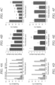
FIGS. 5A-5E illustrates the results of freshly harvested kidney tissue that was minced and digested with collagenase before passing through the two filter devices that were coupled in series.FIGS. 5A and 5B illustrate the evaluation of the 25 or 50 µm membranes combined with the 10 or 15 µm membranes, performed under direct or tangential (60% cross-flow) filtration modes. Single cell count was determined using a cell counter. As seen inFIG. 5A , after 15 min digestion, device treatment increased single cell recovery by 2- to 4-fold for all membrane combinations and filtration modes. Inset image shows tissue captured on a 50 µm pore size membrane.FIG. 5B illustrates how device treatment increased single cell recovery by more than 5-fold for all cases after 30 min digestion. Results were generally based on the second membrane pore size, and did not vary significantly with the first membrane pore size or filtration mode.FIGS. 5C-5E illustrates results of the investigation of the 50-10 and 50-15 combinations using flow cytometry.FIG. 5C shows single tissue cells numbers recovered from the 50-15 and 50-10 membrane combination exceeded controls by 5- to 10-fold at the 15 and 30 min digestion times. After 60 min digestion, the 50-15 µm combination enhanced single tissue cell recovery by 2.5-fold.FIG. 5D shows that viability was -90% for all conditions at the 15 and 30 min digestion times, but decreased after 60 min digestion to -80% for the control and 75% for the 50-15 µm filter combination.FIG. 5E illustrates aggregate and cluster numbers were quantified using scattering information and are presented relative to single cells. Aggregates increased with digestion time for controls, remained the same using the 50-15 membrane combination, but decreased for the 50-10 membrane combination. Error bars represent standard errors from at least three independent experiments. * indicates p < 0.05 and ** indicates p < 0.01 relative to the control at the same digestion time. -
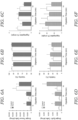
FIGS. 6A-6F illustrate the validation of the integrated dual membrane filter device using murine liver (FIGS. 6A-6C ) and mammary tumor tissue samples (FIGS. 6D-6F ). Freshly harvested murine liver and breast tumor tissue was minced and digested with collagenase before passing through the microfluidic filter device containing 50 and 15 µm membranes. As seen inFIG. 6A , device treatment increased single liver tissue cells by 5-fold and 2-fold after 15 and 30 min digestion, respectively. The device did not increase single liver tissue cells further after 60 min, as enzymatic digestion had fully liberated cells. With reference toFIG. 6B , viability remained greater than 90% for controls and device conditions. As seen inFIG. 6C , aggregates were present at ~1% for controls at all digestion times, and were generally reduced by device treatment. InFIG. 6D , device treatment increased single epithelial cells by 3-fold at all digestion times. As seen inFIG. 6E , cell viability was significantly lower for tumors at 40-50%, but did not vary significantly with digestion time or device treatment. Aggregates constituted about 15-20% of cell suspensions for all conditions (FIG. 6F ). Error bars represent standard errors from at least three independent experiments. * indicates p < 0.05 and ** indicates p < 0.01 relative to the control at the same digestion time. -
FIGS. 7A-7E illustrate single filter device experiments using MCF-7 cells.FIG. 7A shows live single cell numbers for experiments performed under direct filtration mode and 12.5 mL/min flow rate. Values were ~40% higher than the control for each of the 5, 10, and 15 µm pore sizes.FIG. 7B illustrates cell populations obtained for direct filtration experiments at 0.25, 1, and 4 mL/min flow rates.FIGS. 6C-6E illustrate cell populations obtained for tangential filtration experiments using 12.5 mL/min total flow rate and cross-flow ratios of 80% (FIG. 7C ), 60% (FIG. 7D ), and 40% (FIG. 7E ). Error bars represent standard errors from at least three independent experiments. * indicates p < 0.05 and ** indicates p < 0.01 relative to the control. -
FIGS. 8A-8F illustrate double filter device experiments using MCF-7 cells.FIG. 8A illustrates live single cell number for double filter device experiments performed under direct filtration mode and 12.5 mL/min flow rate. Values were lowest for membrane all combinations that included the 5 µm pore size.FIG. 8B Live single cell numbers for double filter device experiments performed under tangential filtration mode, 12.5 mL/min total flow rate, and 60% cross-flow ratio. Values were close to 2-fold greater than control in all cases.FIGS. 8C-8F illustrate the results of double filter device experiments performed under tangential filtration mode, 12.5 mL/min total flow rate, and 80% cross-flow ratio. Results for cell populations (FIG. 8C ), single cell recovery (FIG. 8D ), viability (FIG. 8E ), and live single cell recovery (FIG. 8F ) were similar to 60% cross-flow ratio experiments. Error bars represent standard errors from at least three independent experiments. * indicates p < 0.05 and ** indicates p < 0.01 relative to the control. -
FIGS. 9A-9D illustrates filter device optimization using murine kidney tissue.FIGS. 9A, 9B experiments performed using two single membrane filter devices connected in series. Recoveries are shown forFIG. 9A red blood cells andFIG. 9B leukocytes, which both increased with both digestion time and device processing in a manner consistent with single tissue cell recovery results inFIG. 5C .FIGS. 9C, 9D illustrate experiments performed using the integrated dual membrane filter device with kidney tissue that was digested for 60 min. Single tissue cell number increased by ~60% after device processing relative to the control (FIG. 9C ). Viability remained at >85%, similar to control (FIG. 9D ). Error bars represent standard errors from at least three independent experiments. * indicates p < 0.05 and ** indicates p < 0.01 relative to the control at the same digestion time. -
FIGS. 10A-10D illustrates red blood cell and leukocyte recoveries for murine liver and tumor tissue samples. Results are shown for liver (FIGS. 10A, 10B ) and mammary tumor cell (FIGS. 10C, 10D ) suspensions. Red blood cell and leukocyte cell counts increased with both digestion time and device processing in all cases. Recoveries increased with digestion time and device processing in a manner consistent with single tissue/epithelial cell results inFIGS. 6A-6F . Error bars represent standard errors from at least three independent experiments. * indicates p < 0.05 and ** indicates p < 0.01 relative to the control at the same digestion time. -
FIG. 1A illustrates a cross-sectional view of the microfluidic tissue dissociation andfiltration device 10 according to one embodiment. The microfluidic tissue dissociation andfiltration device 10 is formed in one or more substrates orlayer 12 as best illustrated inFIGS. 1D, 1E ,1F ,1G, and 1H . The substrates or layers 12 may be formed from a polymer or plastic material that contains various features formed therein that are laminated or otherwise bonded together to form the final microfluidic tissue dissociation andfiltration device 10 according to one embodiment. The various features formed in the substrates or layers 12 include the channels and fluid passageways (described below in more detail) through which fluid flows during operation of the microfluidic tissue dissociation andfiltration device 10. - The microfluidic tissue dissociation and
filtration device 10 includes aninlet 14 through which fluid flows into the microfluidic tissue dissociation andfiltration device 10. Theinlet 14 may include abarbed end 40 or the like as illustrated that can be connected to tubing or other conduit that is used to deliver the fluid containing tissue to the microfluidic tissue dissociation andfiltration device 10. Theinlet 14 is fluidically coupled to a firstmicrofluidic channel 16 at an upstream location (arrows indicate the direction of fluid flow). The firstmicrofluidic channel 16 is also coupled to afirst outlet 18 that is located at a downstream location. Thefirst outlet 18 may include abarbed end 40 or the like as illustrated that can be connected to tubing or other conduit that is used to remove fluid containing cells and cell aggregates from the microfluidic tissue dissociation andfiltration device 10. The firstmicrofluidic channel 16 is at least partially defined in one or more of the substrates or layers 12. For example, the surfaces (top, bottom, sides) of the firstmicrofluidic channel 16 may be defined in the one or more of the substrates or layers 12. The typical cross-sectional dimension of the firstmicrofluidic channel 16 may include a height within the range of about 200 µm to about 1 mm and a width within the range of about 1 mm to about 1 cm. The length of the first microfluidic channel 16 (from end to end) may vary from a few centimeters and tens or even hundreds of centimeters (e.g., from about 5 cm to about 100 cm in one example). It should be appreciated that these dimensions are illustrative. - With reference to
FIG. 1A , the microfluidic tissue dissociation andfiltration device 10 includes a secondmicrofluidic channel 20. The secondmicrofluidic channel 20 is, in one embodiment, disposed in a different substrate orlayer 12 of the microfluidic tissue dissociation andfiltration device 10 as seen inFIGS. 1D, 1E ,1F ,1G, and 1H . In this regard, the secondmicrofluidic channel 20 is located in a different plane than the firstmicrofluidic channel 16. For example, the secondmicrofluidic channel 20 may be located in a lower plane than the firstmicrofluidic channel 16. Like the firstmicrofluidic channel 16, the secondmicrofluidic channel 20 may be defined in the one or more of the substrates or layers 12. The typical cross-sectional dimension of the secondmicrofluidic channel 20 may include a height within the range of about 200 µm to about 1 mm and a width within the range of about 1 mm to about 1 cm. The length of the second microfluidic channel 20 (from end to end) may vary from a few centimeters and tens or even hundreds of centimeters (e.g., from about 5 cm to about 100 cm in one example). It should be appreciated that these dimensions are illustrative. - The second
microfluidic channel 20 is fluidically connected to the firstmicrofluidic channel 16 by afluid passageway 22. Thefluid passageway 22 that connects the secondmicrofluidic channel 20 to the firstmicrofluidic channel 16 includes a via, hole, or aperture that extends between the firstmicrofluidic channel 16 to the secondmicrofluidic channel 20. Thefluid passageway 22 may be formed or defined in one ormore layers 12 that are located between thelayers 12 that form the firstmicrofluidic channel 16 and the secondmicrofluidic channel 20. Afirst filter membrane 24 is disposed in or across thefluid passageway 22 and is interposed between the firstmicrofluidic channel 16 and the secondmicrofluidic channel 20. For example, thefirst filter membrane 24 may be formed as a single layer of woven mesh polymer thread that is sandwiched between twoadjacent layers 12 and extends across thefluid passageway 22. In one embodiment, the thread used for thefirst filter membrane 24 is polyamide thread (e.g., Nylon®). The pore diameters that make up thefirst filter membrane 24 may, in one embodiment, may be within the range of about 1 µm to about 100 µm. Pore diameters in this context refers to the nominal or average pore diameter of the particular filter membrane. In another embodiment, thefirst filter membrane 24 may have pore diameters within the range of about 5 µm to about 50 µm. - Referring to
FIG. 1A , the secondmicrofluidic channel 20 is spaced apart from the firstmicrofluidic channel 16 and fluid passes into the secondmicrofluidic channel 20 by entering thefluid passageway 22 and then passing through the first filter membrane 24 (arrows indicate flow direction). In this regard, the secondmicrofluidic channel 20 is in fluidic communication with the firstmicrofluidic channel 16. As seen inFIG. 1A , asecond outlet 26 is coupled to a downstream location of the secondmicrofluidic channel 20. Thesecond outlet 26 may include abarbed end 40 or the like as illustrated that can be connected to tubing or other conduit that is used to remove single cells and fluid from the microfluidic tissue dissociation andfiltration device 10. Asecond filter membrane 28 is disposed in or across afluid passageway 30 that couples the secondmicrofluidic channel 20 to thesecond outlet 26. Thefluid passageway 30 may include a via, hole, or aperture that extends between the secondmicrofluidic channel 20 and thesecond outlet 26. Thefluid passageway 30 may be formed or defined in one ormore layers 12 that are located between thelayers 12 that form the secondmicrofluidic channel 20 and thetop layer 12 that has thesecond outlet 26. Thesecond filter membrane 28 is disposed in or across thefluid passageway 30 and is interposed between the secondmicrofluidic channel 20 and thesecond outlet 26. Like thefirst filter membrane 24, thesecond filter membrane 28 may be formed as a single layer of woven mesh polymer thread that is sandwiched between twoadjacent layers 12 and extends across thefluid passageway 30. - The
second filter membrane 28 may be made from similar materials and have similar, albeit smaller pore sizes than thefirst filter membrane 24. As explained herein, thefirst filter membrane 24 and thesecond filter membrane 28 may be formed using single layer, woven meshes of polymer fibers although they may also be formed using microfabricated membranes or track-etched membranes. Track-etched membranes are formed by exposing a membrane material such as polycarbonate or polyester to charged particles. The charged particles pass through the membrane material creating points of weakness. An etchant is then used to eat away the polymer material along the tracks formed by the charged particles. The etchant widens the tracks into pores of defined sizes. Microfabricated membranes may be formed using photolithographic patterning of polymer materials (either positive or negative patterning). Regardless of how they are made therespective filter membranes first filter membrane 24 has pores having diameters of d1 and thesecond filter membrane 28 has pores having diameters of d2, wherein d1 > d2. This permits progressively smaller filtration of cell aggregates and cells. - As seen in
FIG. 1A , the microfluidic tissue dissociation andfiltration device 10 contains one (1)inlet 14 and two (2)outlets first outlet 18 collects tangential flow effluent while thesecond outlet 26 collects the direct flow effluents that passes through thefirst filter membrane 24 and thesecond filter membrane 28. As explained herein, the microfluidic tissue dissociation andfiltration device 10 is fabricated, in one preferred embodiment, using a commercial laminate process in which the substrates or layers 12 are thin acrylic sheets that are laser-etched and bonded using adhesive and pressure lamination. In some embodiments, as illustrated inFIGS. 1D, 1E ,1F ,1G, 1H a total of seven (7)plastic layers 12 are used, along with Nylon®mesh filter membranes layers 12 withinrespective fluid passageways mesh filter membranes microfluidic channel 16 connects thedevice inlet 14 to thefirst filter membrane 24 and collects the cross-flow across thefirst filter membrane 24 via thetangential flow outlet 18. The secondmicrofluidic channel 20 collects the flow through thefirst filter membrane 24 and directs flow through thesecond filter membrane 28 and out thesecond outlet 26. Note that in some embodiments, thefirst outlet 18 may be plugged or omitted entirely in which case first andsecond filter membranes -
FIGS. 1B ,1D ,1E , and1F illustrate another embodiment of the microfluidic tissue dissociation andfiltration device 10. As in the prior embodiment, the microfluidic tissue dissociation andfiltration device 10 contains one (1)inlet 14 and two (2)outlets first outlet 18 collects tangential flow effluent while thesecond outlet 26 collects the direct flow effluents that passes through thefilter membrane 24. In this embodiment, only asingle filter membrane 24 is employed. The microfluidic tissue dissociation andfiltration device 10 is fabricated using a commercial laminate process in which thin acrylic sheets are laser-etched and bonded using adhesive and pressure lamination. The membrane may include a mesh (e.g., Nylon®)filter membrane 18 with well-defined pore diameter sizes in the range of 5, 10, 15, 25, and 50 µm that is interposed between the firstmicrofluidic channel 14 and the secondmicrofluidic channel 20. In some embodiments, only asingle filter membrane 24 is needed, although performance may be improved using twofilter membranes first outlet 18 may be plugged or omitted entirely in which case first membrane operates in direct flow mode with no tangential flow. -
FIG. 1C illustrates yet another embodiment of a microfluidic tissue dissociation andfiltration device 10. This embodiment illustrates adevice 10 that utilizes afirst filter membrane 24, asecond filter membrane 28, and athird filter membrane 32. Similar aspects to the embodiments disclosed inFIGS. 1A and 1B contain similar reference numbers. In this embodiment, thesecond filter membrane 28 operates on tangential flow with larger aggregates that have passed through thefirst filter membrane 24 being directed out of thesecond outlet 26. Smaller aggregates pass through thesecond filter membrane 28 and enter the thirdmicrofluidic channel 34 which leads to thethird filter membrane 32. Thethird filter membrane 32 is located in afluid passageway 36 that couples the thirdmicrofluidic channel 34 to athird outlet 38. Thefluid passageway 36 may include a via, hole, or aperture that extends between the thirdmicrofluidic channel 34 and thethird outlet 38. Thefluid passageway 36 may be formed or defined in one ormore layers 12 that are located between thelayers 12 that form the thirdmicrofluidic channel 34 and atop layer 12 that has thethird outlet 38. Thethird filter membrane 32 is disposed in or across thefluid passageway 36 and is interposed between the thirdmicrofluidic channel 34 and thethird outlet 38. Like thefirst filter membrane 24, thethird filter membrane 32 may be formed as a single layer of woven mesh polymer thread that is sandwiched between twoadjacent layers 12 and extends across thefluid passageway 36. - To use any of the microfluidic tissue dissociation and
filtration devices 10, a sample solution containing the material to be processed is flowed through thedevice 10 using, for example, one or more pumps (not shown). Pumps may be provided to push or even pull material through thedevice 10. Thus, the pumps may be fluidically connected to theinlet 14 or theoutlets outlets 18, 26) may be recirculated back into theinlet 14 so that the material to be processed makes multiple passes through the microfluidic tissue dissociation andfiltration device 10. Numerous biological materials may be processed using thedevice 10. This includes, by way of example, tissue, tissue fragments, digested tissue, un-digested tissue, and cellular aggregates. The tissue may be healthy tissue or diseased tissue. In some embodiments, the microfluidic tissue dissociation andfiltration device 10 may be coupled to other devices at the upstream or downstream ends. For example, tissue dissociation devices such as the hydro-mincing or branched microfluidic device may be coupled upstream of thedevice 10 where processed tissue leads to theinlet 14. Theoutlets - The microfluidic tissue dissociation and
filtration device 10 was designed to remove tissue fragments and cell aggregates produced by standard enzymatic digestion procedures or comparable microfluidic processing. This enhances single cell purity for downstream diagnostic applications, and any aggregates that were retained could be further processed to increase overall cell recovery. A schematic of thedevice 10 that was used for experiments is shown inFIG. 1A . Sample is introduced via theinlet 14 and comes into contact with amicroporous filter membrane 24. Sample that passes through thefilter membranes membrane 24 and exit through thecross-flow outlet 18. This arrangement was chosen to maximize device utility by enabling operation in either direct or tangential filtration modes. Under direct filtration, all of the sample would pass through the membrane to maximize sample recovery and processing speed. Under tangential flow, the cross-flow would sweep larger tissue fragments and cell aggregates away from the membrane surface to prevent clogging. However, not all of the sample would be filtered, requiring multiple passes to collect the full sample. - Microfluidic tissue dissociation and
filtration devices 10 were fabricated using a commercial laminate approach, with channel features (including channels, vias or holes) were laser micro-machined into hard plastic (polyethylene terephthalate, PET). This provides a more robust device than alternative fabrication methods, such as photolithography and casting of polydimethyl siloxane (PDMS), and thus better supports the high flow rates and pressures that are desired for rapid tissue filtration. A total of seven (7) PET layers 12 were used, including twochannel layers layers layers FIGS. 1D-1H . Two locations were included for mounting thin,microporous filter membranes FIGS. 1A ,1G, 1H . The first location is in the center of thedevice 10, sandwiched between the vialayers filter membrane 24 would be used for either tangential or direct filtration of large tissue fragments and cellular aggregates. It was hypothesized that asecond filter membrane 28 with smaller pores could help maximize single cell purity. This second filter membrane 28 (in those embodiments where used such as illustrated inFIGS. 1A ,1G, 1H ) was placed immediately upstream of theeffluent outlet 26, sandwiched between thebottom channel 12f and vialayer 12e and allows for direct filtration of smaller aggregates and clusters.Hose barbs 40 were mounted in thetop layer 12a to serve asdevice inlets 14 andoutlets devices 10 were assembled by stacking thevarious layers 12 andmembranes - For the
microporous filter membranes FIG. 2 . Moreover, it was hypothesized that the narrow cross-section and rounded shape of the Nylon® threads will be ideal for dissociating aggregates into smaller clusters or even single cells. One would expect a dissociation mechanism to be most prevalent when aggregates are only slightly larger than the pores. This is because aggregates that span many pores are more likely to be captured in a similar manner to traditional filtration. Track-etched membranes were considered, as they are also cheap, easy to use, and have been used extensively in single cell and aggregate filtration studies. However, pores are randomly located and thus tend to overlap at high porosity. Microfabricated membranes offer precise control over pore size, shape, and location and have been used for cell filtration and compartmentalization. However, custom fabrication adds cost and complexity, and the membranes may not be as durable at high porosity. Thus, it was concluded that Nylon® mesh membranes provided the optimal combination of cost and performance characteristics, while also providing potential for aggregate dissociation. - Single cell recovery and viability was first investigated for Nylon® mesh membranes with 5, 10, 15, 25, or 50 µm pore sizes. To eliminate confounding effects, fabricated
devices 10 containing only thefirst membrane 24 were initially used. Thisfirst membrane 24 was used in direct flow mode and not tangential flow mode. Experiments were performed using MCF-7 human breast cancer cells, which are strongly cohesive and provide large numbers of aggregates from standard tissue culture. Note that MCF-7 cells are very large at -20 µm diameter. Cell suspensions were passed through devices using a syringe pump, and initial tests were performed using direct filtration at 12.5 mL/min. Device effluents were recovered and imaged under phase contract microscopy to identify single cells, clusters of 2 to 3 cells, small aggregates of 4 to 10 cells, and large aggregates of >10 cells. Recovery results for each population are plotted inFIG. 3A . Large and small aggregates constituted 10% and 15% of the control population, respectively. These percentages decreased after filtration, in accordance with pore size, down to <0.5% for the 5 and 10 µm pores. Single cells were initially present at less than 30%, and progressively rose as pore size decreased, reaching a maximum of 85%. Clusters remained around 40-45% for all but the 5 and 10 µm pore sizes, but even then, clusters were still present at a substantial level. - Single cell numbers using a cell counter were quantified, and results are plotted in
FIG. 3B after normalization by the control. For the 50 µm pore size, ~15% of single cells were lost, most likely due to holdup or non-specific adhesion within thedevice 10. For all other pore sizes, more single cells were recovered after filtration, suggesting that a percentage of the aggregate and/or cluster populations were dissociated into single cells. Dissociation became more pronounced as pore size decreased, with single cells increasing by more than 5-fold for the 5 µm pore size. However, extruding cells through smaller pores compromised viability, as determined by flow cytometry using a propidium iodide exclusion assay (FIG. 3C ). Specifically, losses in viability scaled inversely with single cell recovery. As a result, the number of viable single cells that were recovered remained constant, around 40% higher than the control, for the 5, 10, and 15 µm pore sizes (seeFIGS. 7A-7E ). - The effect of flow rate was examined while still utilizing the direct filtration mode. It was found that decreasing flow rate to as low as 0.25 mL/min resulted in general trends toward lower single cell numbers and higher viability, but these changes were not significant (
FIGS. 3D-3E ). Aggregate, cluster, and single cell percentages were also similar for each flow rate (seeFIGS. 7A-7E ). Finally, tangential filtration mode was investigated by diverting the sample between thecross-flow outlet 18 andeffluent outlet 26 using two syringe pumps that were operated in withdrawal mode. The total flow rate was held constant at 12.5 mL/min, similar to direct filtration experiments, while the cross-flow was varied from 40 to 80%. Afterwards, sample collected from the cross-flow outlet was passed through the filter membrane in direct filtration mode at 12.5 mL/min, and both effluents were combined prior to analysis. It was found that single cell numbers were similar at all cross-flow ratios (FIG. 3F ), which were significantly lower than direct filtration experiments at 12.5 mL/min (compare toFIG. 3B ). In fact, single cell numbers under tangential filtration were similar to direct filtration at 0.25 mL/min, even though all tangential experiments were performed utilized higher membrane flow-through rates (>2.5 mL/min). It was found that tangential filtration removed large aggregates more effectively at the 50 µm pore size (seeFIGS. 7A-7E ). Taken together, it was concluded that under pressure driven flow, aggregate and cluster dissociation depended primarily on membrane pore size and whether a cross-flow was present, and less so on the flow rate through the membrane. - Based on these results, it was postulated that aggregate dissociation could be enhanced by passing samples through two Nylon® membranes in series. This is because the first membrane would reduce aggregate size such that the second membrane could better liberate single cells. Therefore, two single-membrane filter devices were coupled in series using tubing and performed direct filtration experiments at 12.5 mL/min. Since dissociation was the focus, the smaller pore size membranes were tested in various combinations. It was found that passing MCF-7 suspensions through two filter devices eliminated nearly all aggregates (
FIG. 4A ), even for the 15 µm pore size. Clusters were also reduced relative to the single filter experiments (compare toFIG. 3A ), reaching a low of 9% for the 5-5 membrane combination. Single cell number and viability results are presented inFIG. 4B and FIG. 4C , respectively. Single cell yield did not change for the 5-5 and 10-5 membrane combinations relative to the single filter case (compare toFIG. 3B ), as samples were already well-dissociated. - However, the 15-5 membrane combination produced fewer single cells, suggesting that the 15 µm membrane captured aggregates that the 5 µm membrane would have been able to dissociate into single cells. For the 10 µm membrane, single cell numbers were similar between single and double filter device experiments. The only case in which the use of two membranes was beneficial was for the 15-15 membrane combination, which increased single cell numbers increased from 50% to 150% higher than the control. It was found that cell viability was predominantly determined by the pore size of the second, smaller membrane, and that values were similar to the single filter device experiments (compare to
FIG. 3C ). While it was observed that viability was generally correlated with single cell numbers, live single cell numbers were lowest for conditions that employed the 5 µm membrane (seeFIGS. 8A-8F ). Thus, the 5 µm pores were deemed too small, at least for these ~20 µm MCF-7 cells. For the 10-10, 15-10, and 15-15 membrane combinations, live single cell recovery was ~60% higher than the control. For context, this level of dissociation is comparable to the best version of the branching channel dissociation device for the same MCF-7 cell model. - Next, the 10 and 15 µm membranes were investigated in combination with the larger 25 and 50 µm membranes. Two
filter devices 10 were coupled in series as previously described, but now experiments were performed under tangential filtration. As withsingle filter device 10 experiments, total flow rate was held constant at 12.5 mL/min and sample collected from the cross-flow outlet was passed through both devices under direct filtration mode. Using 60% cross-flow, it was found that single cell, cluster, and aggregate populations were similar to the direct flow experiments utilizing the same 10 and 15 µm membranes (FIG. 4D ). However, a small number of aggregates were recovered from the 50-15 membrane combination. Single cell recovery and viability results were also generally determined by the second, smaller membrane (FIGS. 4E and 4F ). As such, single cell numbers for the 10 µm pore size were similar to direct flow experiments using either one or two filter devices. For the 15 µm pore size, single cell numbers were similar to the 15-15 membrane combination under direct filtration, but now viability was significantly higher and equal to the control. It was unclear whether this change was related to using larger pore sizes in the upstream filter device, tangential filtration mode, or a combination of both. In total, live single cell numbers were ~2-fold greater than the control for all but the 25-15 combination (seeFIGS. 8A-8F ). Note that nearly identical results were obtained for tangential filtration experiments performed using 80% cross-flow (seeFIGS. 8A-8F ). Based on the combined results obtained with the MCF-7 cell aggregate model, one can conclude that the second membrane predominantly dictated single cell recovery and viability because of its smaller pore size and consistent utilization of the direct filtration mode. Placing a second membrane upstream could improve results in some cases, particularly for the 15 µm membrane, but the pore size and operational mode of the first membrane was less important. - Since the ultimate goal is to use the filter devices with complex tissues, the performance was evaluated using murine kidney tissue samples. The two microfluidic tissue dissociation and
filtration devices 10 in series was used, specifically the larger 25 or 50 µm pore sizes followed by smaller 10 or 15 µm pore sizes. The first filtration was performed under direct or tangential (60% cross-flow) mode, and a total flow rate of 12.5 mL/min. Fresh kidneys were harvested, sliced into histologically similar sections with a scalpel, minced into ~1 mm3 pieces, and weighed. Samples were then digested with collagenase and mechanically treated by vortexing and pipetting, per routine protocol. Device performance was initially evaluated using tissue samples that were only briefly digested with collagenase, as this would prove the most stringent test of membrane clogging and dissociation power. After digestion for 15 min, device treatment increased single cell numbers by at least 2-fold for all membrane combinations and filtration modes (FIG. 5A ). Maximal results were ~4-fold higher than control, which were obtained for both 25 µm pore size combinations under direct filtration and both 50 µm pore size combinations under tangential filtration. Increasing digestion time to 30 min enhanced single cell recovery for all device conditions, which were now at least 5-fold higher than the control (FIG. 5B ). Results were generally greater for the 15 µm pore combinations regardless of the first membrane size or operational mode, which was consistent with the findings with the MCF-7 aggregate model. For both 15 and 30 min digestion times, it was observed that large pieces of tissue were trapped by the first membrane (FIG. 5A ), but membrane fouling was not an issue for either direct or tangential filtration modes, most likely because relatively small tissue samples (<100 mg) were used. - Based on these preliminary results, it was decided to further evaluate cell suspensions using flow cytometry. Specifically, a panel of stains were used to assess cell viability and identify red blood cells and leukocytes. Also, only the 50 µm pore size was used in the first device due to higher porosity and the direct filtration mode since it was faster and easier to execute. The number of single tissue cells recovered per mg tissue is shown in
FIG. 5C . Results at the 15 and 30 minute digestion times were similar to the cell counter data inFIGS. 5A and 5B , with both 50-10 and 50-15 membrane combinations producing 5- to 10-fold more single cells than the control. Digesting for 60 min resulted in a dramatic increase in single tissue cell numbers to ~20,000/mg. The 50-10 membrane combination was similar to the control, but the 50-15 membrane combination enhanced recovery by 2.5-fold. Notably, the 50-15 membrane combination also produced similar numbers of single tissue cells after digesting for 15 min as the control after digesting for 60 min. Cell viability was -90% for all conditions at the 15 and 30 minute digestion time points (FIG. 5D ). However, 60 min digestion decreased viability to ~80% for the control and -75% for the 50-15 µm filter combination. Scattering information was also used to quantify the percentage of aggregates relative to single cells (FIG. 5E ). Note that samples were passed through a 35 µm cell strainer prior to analysis to prevent clogging of the cytometer, and thus results likely only reflect cell clusters. Aggregate percentage increased progressively with digestion time for controls, from 3 to 11%, indicating that traditional dissociation methods are not effective at reducing tissue all the way down to single cells. Aggregate percentages remained unchanged for the 50-15 membrane combination, but the 50-10 membrane combination reduced aggregates by approximately half at the 30 and 60 minute digestion time points. Red blood cell and leukocyte recoveries are shown inFIGS. 9A-9D , and closely mirrored the single tissue cell recovery results inFIG. 5C . - Based on the superior performance of the 50-15 membrane combination in terms of single tissue cells recovered from kidney samples, a single microfluidic tissue dissociation and
filtration device 10 was fabricated containing bothmembranes FIGS. 1A ,1G, 1H . Thedouble membrane device 10 was first validated using murine kidney samples that were digested for 60 min, and performance in terms of single tissue cell recovery and viability was comparable to the previous results obtained with two single filter devices coupled in series (seeFIGS. 9A-9D ). Freshly resected murine liver samples were tested, which are generally easier to enzymatically digest, but hepatocytes are also well-known to be fragile. After a brief 15 min digestion, approximately 2,500 single tissue cells were obtained per mg liver tissue for the control, and this was enhanced 5-fold by filter device treatment (FIG. 6A ). At 30 min, single tissue cells increased by 2-fold for the control, but device treatment remained static, resulting in a more modest 2-fold improvement. Both control and device conditions were both much higher after 60 min digestion, around 40,000 single tissue cells/mg, indicating that the liver tissue had been fully broken down by enzymatic digestion. Viability remained greater than 90% for all conditions (FIG. 6B ), which was very encouraging considering the fragile nature of hepatocytes. Aggregates were present at ~1% for controls at all digestion times, and were generally reduced by device treatment although differences were not significant (FIG. 6C ). As a final evaluation, mammary tumors were used that spontaneously arise in MMTV-PyMT transgenic mice. Tumors are generally considered among the most difficult epithelial tissues to dissociate due to their abnormal extracellular matrix composition. For these tests, the flow cytometry detection panel was modified by adding an antibody specific for the general epithelial marker EpCAM. This enabled the positive identification of epithelial tissue cells, although this would include both normal and cancerous cells. Control conditions produced ~1,000 single epithelial cells per mg tumor tissue at both the 15 and 30 min digestion time points, and this only increased to ~2,000 cells/mg after 60 min digestion (FIG. 6D ). Device treatment enhanced single cell recovery by approximately 3-fold at all time points. Epithelial cell viability was only ~40-50% for all conditions (FIG. 6E ), potentially indicating that the tumor samples contained highly necrotic regions. A significant number of aggregates were present at all conditions, in the range of 15-20% of the total recovered population (FIG. 6F ). This suggests that more dissociation power will be needed to effectively liberate all cells from tumors. For both liver and tumor samples, red blood cell and leukocyte recoveries followed similar trends as the single liver tissue cell and single epithelial cell data (seeFIGS. 10A-10D ). - A new microfluidic tissue dissociation and
filtration device 10 is disclosed that is simple and inexpensive, but can also rapidly and effectively improve the quality of single cell suspensions obtained from digested tissue samples. This was accomplished using Nylon® mesh membranes with well-defined, micron-scale pores that simultaneously filtered larger tissue fragments and dissociated smaller aggregates into single cells. Specifically, it was demonstrated that using two Nylon® mesh membranes; afirst filter membrane 24 with a larger pore size in the range of 25-50 µm followed by asecond filter membrane 28 with a smaller pore size in the range of 10-15 µm, resulted in dissociation of aggregates into progressively smaller sizes and ultimately enhanced single cell recovery. The dissociation effect was likely due to the combination of hydrodynamic shear forces and physical interaction with the Nylon® threads. While this was effective, note that care must be given to prevent cell damage, particularly for complex tissues that may contain cells of different sizes. Using the final dual membrane microfluidic tissue dissociation andfiltration device 10 with 50 and 15 µm pore sizes in therespective filter membranes - The design also included the option to perform the first filtration (e.g., using filter membrane 24) under tangential mode, although this was not found to be critical for generating single cells. Note that it is possible that tangential filtration could become more important if tissue size were scaled up beyond 100 mg. Also, the microfluidic tissue dissociation and
filtration device 10 can be integrated with a hydro-mincing digestion device such as that disclosed inU.S. Patent Application Publication No. 2019/0070605 , to enable automated processing of cm-scale tissue samples. The microfluidic tissue dissociation andfiltration device 10 can also be integrated as well with the branching channel dissociation device such as that disclosed inU.S. Patent No. 9,580,678 filtration device 10 can be integrated with downstream technologies to enable on-chip sorting and analysis of single cells to create point-of-care diagnostic platforms for tissue samples. - It should also be understood that the invention is not necessarily limited to having two
filter membranes single filter membrane 24 may be necessary. In addition, even though thedevice 10 may have multiple filter membranes (e.g., 24, 28, 32) it may be possible to shunt fluid to avoid one or more of the filter membranes that are located in thedevice 10. This may be accomplished by plugging or blocking flow in one of theoutlets filtration device 10 may have more than two filters such as the embodiment illustrated inFIG. 1C . - Device fabrication. Microfluidic devices were fabricated by ALine, Inc. (Rancho Dominguez, CA). Briefly, fluidic channels, vias, and openings for membranes and hose barb were etched into polyethylene terephthalate (PET) layers using a CO2 laser. Nylon® mesh membranes were purchased from Amazon Small Parts (10, 15, 25, and 50 µm pore sizes; Seattle, WA) or EMD Millipore (5 µm; Burlington, MA) as large sheets and were cut to size using the CO2 laser. Device layers, Nylon® mesh membranes, and hose barbs were then assembled, bonded using adhesive, and pressure laminated to form a single
monolithic device 10. - Cell culture aggregate model and murine tissue samples. MCF-7 human breast cancer cell line was purchased from ATCC (Manassas, VA). Cells were cultured at 37°C and 5% CO2 in tissue culture flasks using DMEM media containing 10% FBS, non-essential amino acids, 1 mM sodium pyruvate, 2 mM L-Glutamine, 100 µg/mL streptomycin, 100 U/mL penicillin, and 44U/L Novolin R insulin (Thermo Fisher, Waltham, MA). Prior to experiments, confluent monolayers were briefly digested for 5 min with trypsin-EDTA, which released cells with a substantial number of aggregates. Cell suspensions were then centrifuged and resuspended in PBS containing 1% BSA (PBS+). Kidneys and liver were harvested from freshly sacrificed BALB/c or C57B/6 mice (Jackson Laboratory, Bar Harbor, ME) that were determined to be waste from a research study approved by the University of California, Irvine's Institutional Animal Care and Use Committee (courtesy of Dr. Angela G. Fleischman). Mammary tumors were harvested from freshly sacrificed MMTV-PyMT mice (Jackson Laboratory, Bar Harbor, ME). For kidneys, a scalpel was used to prepare ~1 cm long x ~1 mm diameter strips of tissue, each containing histologically similar portions of the medulla and cortex. Each tissue strip was then further minced with a scalpel to ~1 mm3 pieces. Liver and mammary tumors were uniformly minced with a scalpel to ~1 mm3 pieces. Minced tissue samples were then weighed, placed within microcentrifuge tubes along with 300 µL of 0.25% collagenase type I (Stemcell Technologies, Vancouver, BC), digested at 37°C in a shaking incubator under gentle agitation for 15, 30, or 60 min, and mechanically disaggregated by repeated pipetting and vortexing. Finally, cell suspensions were treated with 100 Units of DNase I (Roche, Indianapolis, IN) for 10 min at 37°C and washed by centrifugation into PBS+.
- Dissociation and filtration studies. Microfluidic filter devices were prepared by affixing 0.05" ID tubing (Saint-Gobain, Malvern, PA) to the device inlet and outlet hose barbs. Prior to experiments, devices were incubated with SuperBlock (PBS) blocking buffer (Thermo Fisher Scientific, Waltham, MA) at room temperature for 15 min to reduce non-specific binding of cells to the membranes and channel walls and washed with PBS+. MCF-7 cells or digested murine tissue samples were loaded into a syringe and passed through the device using a syringe pump (Harvard Apparatus, Holliston, MA) at total flow rates ranging from 0.25 to 12.5 mL/min. For tangential filtration experiments, two syringe pumps were employed in withdrawal mode, one each connected to the cross-flow and effluent outlets. The withdrawal rates were adjusted to achieve a given cross-flow rate, while total flow rate was always maintained at 12.5 mL/min. Following the initial pass, sample collected from the cross-flow outlet was passed directly through the membrane at 12.5 mL/min and collected from the effluent outlet. Following all experiments, devices were washed with 1 mL PBS+ to flush out any remaining cells, and all effluents were combined into a single sample. Cell counts were obtained using a Moxi Z automated cell counter and type S cassettes (Orflo, Hailey, ID).
- Quantifying cell aggregates by microscopy. Single cells and aggregates were assessed by microscopy. Briefly, MCF-7 cell suspensions were imaged with a Hoffman phase contrast microscope and a 4x objective. Raw images were then converted to binary using MATLAB, and ImageJ was used to identify, outline, and calculate the area of all contiguous cellular units. Each unit was then classified based on area as a single cell (20 to 80 pixels2 or 75 to 300 µm2), cluster (80 to 200 pixels2 or 300 to 750 µm2), small aggregate (200 to 300 pixels2 or 750 to 1120 µm2), or large aggregate (>300 pixels2 or >1120 µm2). Referencing back to the micrographs, this corresponded to ~2 to 3 cells for clusters, ~4-10 cells for small aggregates, and >10 cells for large aggregates.
- Flow cytometry. The flow cytometry protocol that was previously developed for tissue suspensions was followed. Briefly, cell suspensions were co-stained with 2.5µg/mL anti-mouse CD45-PE monoclonal antibody (clone 30-F11, BioLegend, San Diego, CA) and 0.5X CellMask Green (Thermo Fisher, Waltham, MA) for 20 minutes at 37°C. Samples were then washed twice using PBS+ by centrifugation, co-stained with 5 µg/mL 7-AAD (BD Biosciences, San Jose, CA) and 12.5 µM DRAQ5 (BioLegend) on ice for at least 15 minutes, and analyzed on an Accuri C6 Flow Cytometer (BD Biosciences). Flow cytometry data was compensated and analyzed using FlowJo software (FlowJo, Ashland, OR), and a sequential gating scheme was used to identify live and dead single tissue cells from leukocytes, red blood cells, non-cellular debris, and cellular aggregates.
- Statistics. Data are represented as the mean ± standard error. Error bars represent the standard error from at least three independent experiments. P-values were calculated from at least three independent experiments using students t-test.
- While embodiments of the present invention have been shown and described, various modifications may be made without departing from the scope of the present invention. For example, the microfluidic tissue dissociation and
filtration device 10 has been illustrated as including one, two, or threefilter membranes outlet 16 that is used to collect the cross-flow solution (that does not pass directly through the filter membrane) may be turned off or omitted entirely in other embodiments.
Claims (15)
- A microfluidic tissue dissociation and filtration device (10) comprising:an inlet (14) coupled to a first microfluidic channel (16) at an upstream location, the first microfluidic channel (16) coupled to a first outlet (18) at a downstream location, the first microfluidic channel (16) located in a first plane of the microfluidic tissue dissociation device (10);a first filter membrane (24) interposed between the first microfluidic channel (16) and a second microfluidic channel (20), wherein the second microfluidic channel (20) is in fluidic communication with the first microfluidic channel (16) via the first filter membrane (24) and wherein the second microfluidic channel (20) is located in a second plane of the microfluidic tissue dissociation device (10) and the first filter membrane (24) is disposed in a via, hole, or aperture formed between the first microfluidic channel (16) and the second microfluidic channel (20); anda second outlet (26) coupled to a downstream location of the second microfluidic channel (20).
- The microfluidic tissue dissociation and filtration device (10) of claim 1, wherein the first filter membrane (24) has pore diameters within the range of about 5 µm to about 1,000 µm.
- The microfluidic tissue dissociation and filtration device (10) of claim 1, wherein the microfluidic tissue dissociation and filtration device (10) comprises a laminate structure formed by a plurality of layers (12), wherein the first microfluidic channel (16) and the second microfluidic channel (20) are formed in different layers (12).
- The microfluidic tissue dissociation and filtration device (10) of claim 1, further comprising a pump coupled to one or more of the inlet (14), the first outlet (18), or the second outlet (26).
- The microfluidic tissue dissociation and filtration device (10) of claim 1, wherein the first filter membrane (24) comprises a single layer of woven mesh polymer thread.
- The microfluidic tissue dissociation and filtration device (10) according to claim 3, wherein:the first microfluidic channel (16) is disposed in a first layer (12) of the laminate structure;the second microfluidic channel (20) is disposed in a second layer (12) of the laminate structure; anda second filter membrane (28) is interposed between the second outlet (26) and the second microfluidic channel (20).
- The microfluidic tissue dissociation and filtration device (10) of claim 6, wherein the first filter membrane (24) comprises pores having diameters of d1 and wherein the second filter membrane (28) comprises pores having diameters of d2, wherein d1 > d2.
- The microfluidic tissue dissociation and filtration device (10) of claim 7, wherein the first filter membrane (24) has pore diameters of about 50 µm and the second filter membrane (28) has pore diameters of about 15 µm.
- The microfluidic tissue dissociation and filtration device (10) of claim 7, wherein the first filter membrane (24) has pore diameters greater than 15 µm and less than 1,000 µm and the second filter membrane (28) has pore diameters greater than 5 µm and less than or equal to 100 µm.
- The microfluidic tissue dissociation and filtration device (10) of claim 6, further comprising a pump coupled to one or more of the inlet (14), the first outlet (18), or the second outlet (26).
- The microfluidic tissue dissociation and filtration device (10) of claim 6, wherein the first filter membrane (24) and the second filter membrane (28) comprise a single layer of woven mesh polymer thread.
- The microfluidic tissue dissociation and filtration device (10) according to claim 6, further comprising:one or more additional microfluidic channels (34) disposed in different layers (12) of the laminate structure, wherein each of the one or more additional microfluidic channels (34) has respective outlets (38) coupled thereto and respective filter membranes (32) interposed between adjacent microfluidic channels.
- A method of using the microfluidic tissue dissociation and filtration device (10) of any one of claims 1-12, comprising flowing a solution containing a minced sample of tissue into the inlet (14).
- The method of using the microfluidic tissue dissociation and filtration device (10) of claim 13, wherein the output of the first outlet (18) is recirculated to the inlet (14).
- The method of using the microfluidic tissue dissociation and filtration device (10) of claim 13, wherein output from at least one of the first outlet (18) and the second outlet (26) comprise living cells.
Applications Claiming Priority (2)
| Application Number | Priority Date | Filing Date | Title |
|---|---|---|---|
| US201862678171P | 2018-05-30 | 2018-05-30 | |
| PCT/US2019/034470 WO2019232100A1 (en) | 2018-05-30 | 2019-05-29 | Microfluidic filter device and method for dissociation of tissue and cell aggregates and enrichment of single cells |
Publications (3)
| Publication Number | Publication Date |
|---|---|
| EP3801809A1 EP3801809A1 (en) | 2021-04-14 |
| EP3801809A4 EP3801809A4 (en) | 2021-07-28 |
| EP3801809B1 true EP3801809B1 (en) | 2024-05-15 |
Family
ID=68697326
Family Applications (1)
| Application Number | Title | Priority Date | Filing Date |
|---|---|---|---|
| EP19811784.8A Active EP3801809B1 (en) | 2018-05-30 | 2019-05-29 | Microfluidic filter device and method for dissociation of tissue and cell aggregates and enrichment of single cells |
Country Status (6)
| Country | Link |
|---|---|
| US (1) | US12292046B2 (en) |
| EP (1) | EP3801809B1 (en) |
| JP (1) | JP7455389B2 (en) |
| CN (1) | CN112512656A (en) |
| CA (1) | CA3101987A1 (en) |
| WO (1) | WO2019232100A1 (en) |
Families Citing this family (14)
| Publication number | Priority date | Publication date | Assignee | Title |
|---|---|---|---|---|
| US12453812B2 (en) | 2019-06-24 | 2025-10-28 | The Regents Of The University Of California | Integrated system for mechanical processing of lipoaspirate |
| WO2022081488A1 (en) * | 2020-10-12 | 2022-04-21 | The Regents Of The University Of California | Integrated microfluidic system for the processing of tissues into cellular suspensions |
| CA3211524A1 (en) * | 2021-02-19 | 2022-08-25 | The Regents Of The University Of California | Microfluidic device for the digestion of tissues into cellular suspensions |
| US20230066039A1 (en) * | 2021-09-01 | 2023-03-02 | Global Life Sciences Solutions Usa Llc | Perfusion filter membrane and method of use |
| US12241050B2 (en) | 2021-09-01 | 2025-03-04 | Global Life Sciences Solutions Usa, Llc | Perfusion filter assembly for increased cross flow |
| US12606788B2 (en) | 2021-09-01 | 2026-04-21 | Global Life Sciences Solutions Usa Llc | Perfusion filter membrane assembly |
| US12252678B2 (en) | 2021-12-01 | 2025-03-18 | Microfluidx Ltd | Systems and methods for bioprocessing |
| WO2023099898A1 (en) * | 2021-12-01 | 2023-06-08 | Microfluidx Ltd | Systems and methods for bioprocessing |
| CN115232724B (en) * | 2021-12-24 | 2025-06-17 | 康沃思(天津)生物科技有限公司 | Acoustic fluidic device for rapid tissue lysis and automated lysis and biopsy device |
| JPWO2023190803A1 (en) * | 2022-03-30 | 2023-10-05 | ||
| CN115228521B (en) * | 2022-07-01 | 2024-06-04 | 清华大学 | Biological particle separating device and microfluidic chip |
| CN117101744B (en) * | 2023-08-10 | 2026-02-17 | 华中科技大学 | Pneumatic centrifugal separation chip for exosome |
| CN120310627A (en) * | 2025-04-24 | 2025-07-15 | 河南省科学院物理研究所 | A "bottom-up" microfluidic cell capture method based on single-cell filtration membrane |
| CN120866040B (en) * | 2025-09-26 | 2025-12-26 | 深圳汇芯生物医疗科技有限公司 | Exosome purification device |
Family Cites Families (25)
| Publication number | Priority date | Publication date | Assignee | Title |
|---|---|---|---|---|
| US6806543B2 (en) * | 2002-09-12 | 2004-10-19 | Intel Corporation | Microfluidic apparatus with integrated porous-substrate/sensor for real-time (bio)chemical molecule detection |
| WO2004101743A2 (en) * | 2003-05-06 | 2004-11-25 | Bellbrook Labs, Llc | Three dimensional cell cultures in a microscale fluid handling system |
| US7125672B2 (en) | 2003-05-07 | 2006-10-24 | E. I. Du Pont De Nemours And Company | Codon-optimized genes for the production of polyunsaturated fatty acids in oleaginous yeasts |
| JP5278913B2 (en) * | 2007-08-01 | 2013-09-04 | 国立大学法人東京農工大学 | Single cell capture microchannel device |
| WO2009098698A2 (en) | 2008-02-07 | 2009-08-13 | Shahar Cohen | Compartmental extract compositions for tissue engineering |
| US20110151479A1 (en) * | 2008-08-25 | 2011-06-23 | University Of Washington | Microfluidic systems incorporating flow-through membranes |
| US20100059443A1 (en) | 2008-09-02 | 2010-03-11 | Natrix Separations Inc. | Chromatography Membranes, Devices Containing Them, and Methods of Use Thereof |
| KR101276187B1 (en) | 2010-10-25 | 2013-06-18 | 주식회사 싸이토젠 | Cells collection apparatus |
| US20150118728A1 (en) * | 2012-04-20 | 2015-04-30 | Agency For Science, Technology And Research | Apparatus and method for separating a biological entity from a sample volume |
| JP2014113064A (en) | 2012-12-06 | 2014-06-26 | Olympus Corp | Cell separator |
| US9580678B2 (en) * | 2013-06-21 | 2017-02-28 | The Regents Of The University Of California | Microfluidic tumor tissue dissociation device |
| JP6251998B2 (en) | 2013-07-05 | 2017-12-27 | 日立化成株式会社 | Cell capture system and method for operating cell capture system |
| US20150166956A1 (en) | 2013-12-16 | 2015-06-18 | General Electric Company | Devices for separation of particulates, associated methods and systems |
| JP6240785B2 (en) * | 2013-12-20 | 2017-11-29 | スリーエム イノベイティブ プロパティズ カンパニー | System and method for sample concentration and detection |
| JP2016052300A (en) | 2014-09-03 | 2016-04-14 | 日立化成株式会社 | Biological material capture system |
| DE102015204793A1 (en) * | 2015-03-17 | 2016-09-22 | Robert Bosch Gmbh | Apparatus and method for processing a sample of biological material containing target cells |
| JP6722023B2 (en) | 2015-04-03 | 2020-07-15 | 株式会社カネカ | Cell separation filter and method for producing cell concentrate using the same |
| KR102713290B1 (en) * | 2015-09-29 | 2024-10-04 | 도쿄 오카 고교 가부시키가이샤 | Substrate, structure, method for producing structure, method for selecting cells, method for producing cells, and method for producing secretion |
| JP2019022867A (en) | 2015-12-14 | 2019-02-14 | 株式会社村田製作所 | Filtration device |
| US10722540B1 (en) | 2016-02-01 | 2020-07-28 | The Regents Of The University Of California | Microfluidic device and method for shear stress-induced transformation of cells |
| IL295611B2 (en) | 2016-06-08 | 2023-11-01 | Univ California | Method and device for processing tissues and cells |
| JPWO2018003476A1 (en) | 2016-06-30 | 2019-01-17 | 富士フイルム株式会社 | Cell suspension membrane separation method and cell culture apparatus |
| KR101821049B1 (en) | 2016-07-15 | 2018-01-23 | 한국과학기술원 | Quasi-aligned 1D Polymer Nanofibers Grid structure Cross-Laminated, Pore distribution and Pore size controlled 3D Polymer Nanofibers Membrane and Manufacturing Method thereof |
| CN110520735B (en) * | 2017-04-14 | 2024-07-09 | 文塔纳医疗系统公司 | Size-based separation of dissociated fixed tissues |
| US10926257B2 (en) | 2017-08-28 | 2021-02-23 | The Regents Of The University Of California | Microfluidic device for the digestion of tissues into cellular suspensions |
-
2019
- 2019-05-29 US US17/058,634 patent/US12292046B2/en active Active
- 2019-05-29 CA CA3101987A patent/CA3101987A1/en active Pending
- 2019-05-29 WO PCT/US2019/034470 patent/WO2019232100A1/en not_active Ceased
- 2019-05-29 EP EP19811784.8A patent/EP3801809B1/en active Active
- 2019-05-29 JP JP2020566610A patent/JP7455389B2/en active Active
- 2019-05-29 CN CN201980050989.8A patent/CN112512656A/en active Pending
Also Published As
| Publication number | Publication date |
|---|---|
| CA3101987A1 (en) | 2019-12-05 |
| JP7455389B2 (en) | 2024-03-26 |
| US20210205810A1 (en) | 2021-07-08 |
| EP3801809A4 (en) | 2021-07-28 |
| CN112512656A (en) | 2021-03-16 |
| JP2021525516A (en) | 2021-09-27 |
| US12292046B2 (en) | 2025-05-06 |
| WO2019232100A1 (en) | 2019-12-05 |
| EP3801809A1 (en) | 2021-04-14 |
Similar Documents
| Publication | Publication Date | Title |
|---|---|---|
| US12292046B2 (en) | Microfluidic filter device and method for dissociation of tissue and cell aggregates and enrichment of single cells | |
| Qiu et al. | Microfluidic filter device with nylon mesh membranes efficiently dissociates cell aggregates and digested tissue into single cells | |
| US20200283723A1 (en) | Microfluidic tissue dissociation device and method | |
| TWI624294B (en) | Method and device for sample processing | |
| US10926257B2 (en) | Microfluidic device for the digestion of tissues into cellular suspensions | |
| JP2001507986A (en) | Filtration cassette material and filter made of it | |
| TW201329231A (en) | Method and device for isolation of non-fat cells from an adipose tissue | |
| JP2020535840A (en) | System for utilizing cross-flow filtration for cell enrichment | |
| KR101275744B1 (en) | Metal screen filter | |
| EP2507382A2 (en) | Methods and apparatus for segregation of particles, including segregation and proliferation of fetal and stem cells | |
| CN112680357A (en) | Microorganism recovery method and microorganism recovery apparatus | |
| JP2023548659A (en) | Integrated microfluidic system for tissue processing into cell suspensions | |
| US12036550B2 (en) | Microfluidic device for the digestion of tissues into cellular suspensions | |
| Mane et al. | Microfluidic systems for isolation of white blood cells: from design to practical applications | |
| CN108441471B (en) | Method for separating rare cells in blood | |
| EP3110467B1 (en) | Cell filter separation system | |
| CN213203042U (en) | An exosome microfluidic filtration system | |
| JP2024506928A (en) | Microfluidic device for digesting tissue into cell suspensions | |
| US12305166B2 (en) | Separation and collection device for cells and biomolecules, and testing system | |
| Ao, Ph. D et al. | Microfabricated Filter Membranes for Capture and Characterization of Circulating Tumor Cells (CTCs) |
Legal Events
| Date | Code | Title | Description |
|---|---|---|---|
| STAA | Information on the status of an ep patent application or granted ep patent |
Free format text: STATUS: THE INTERNATIONAL PUBLICATION HAS BEEN MADE |
|
| PUAI | Public reference made under article 153(3) epc to a published international application that has entered the european phase |
Free format text: ORIGINAL CODE: 0009012 |
|
| STAA | Information on the status of an ep patent application or granted ep patent |
Free format text: STATUS: REQUEST FOR EXAMINATION WAS MADE |
|
| 17P | Request for examination filed |
Effective date: 20201222 |
|
| AK | Designated contracting states |
Kind code of ref document: A1 Designated state(s): AL AT BE BG CH CY CZ DE DK EE ES FI FR GB GR HR HU IE IS IT LI LT LU LV MC MK MT NL NO PL PT RO RS SE SI SK SM TR |
|
| AX | Request for extension of the european patent |
Extension state: BA ME |
|
| RIN1 | Information on inventor provided before grant (corrected) |
Inventor name: HAUN, JERED Inventor name: QIU, XIAOLONG Inventor name: PENNELL, MARISSA NOELANI Inventor name: HUI, ELLIOT E. |
|
| A4 | Supplementary search report drawn up and despatched |
Effective date: 20210628 |
|
| RIC1 | Information provided on ipc code assigned before grant |
Ipc: B01D 11/04 20060101AFI20210622BHEP Ipc: B01D 63/08 20060101ALI20210622BHEP Ipc: B01L 3/00 20060101ALI20210622BHEP Ipc: C12M 3/00 20060101ALI20210622BHEP Ipc: C12N 5/00 20060101ALI20210622BHEP Ipc: F04B 43/04 20060101ALI20210622BHEP Ipc: G01N 1/28 20060101ALI20210622BHEP Ipc: B01D 63/00 20060101ALI20210622BHEP |
|
| DAV | Request for validation of the european patent (deleted) | ||
| DAX | Request for extension of the european patent (deleted) | ||
| GRAP | Despatch of communication of intention to grant a patent |
Free format text: ORIGINAL CODE: EPIDOSNIGR1 |
|
| STAA | Information on the status of an ep patent application or granted ep patent |
Free format text: STATUS: GRANT OF PATENT IS INTENDED |
|
| INTG | Intention to grant announced |
Effective date: 20231208 |
|
| GRAS | Grant fee paid |
Free format text: ORIGINAL CODE: EPIDOSNIGR3 |
|
| GRAA | (expected) grant |
Free format text: ORIGINAL CODE: 0009210 |
|
| STAA | Information on the status of an ep patent application or granted ep patent |
Free format text: STATUS: THE PATENT HAS BEEN GRANTED |
|
| AK | Designated contracting states |
Kind code of ref document: B1 Designated state(s): AL AT BE BG CH CY CZ DE DK EE ES FI FR GB GR HR HU IE IS IT LI LT LU LV MC MK MT NL NO PL PT RO RS SE SI SK SM TR |
|
| REG | Reference to a national code |
Ref country code: CH Ref legal event code: EP |
|
| REG | Reference to a national code |
Ref country code: DE Ref legal event code: R096 Ref document number: 602019052340 Country of ref document: DE |
|
| REG | Reference to a national code |
Ref country code: IE Ref legal event code: FG4D |
|
| REG | Reference to a national code |
Ref country code: NL Ref legal event code: FP |
|
| REG | Reference to a national code |
Ref country code: LT Ref legal event code: MG9D |
|
| PG25 | Lapsed in a contracting state [announced via postgrant information from national office to epo] |
Ref country code: IS Free format text: LAPSE BECAUSE OF FAILURE TO SUBMIT A TRANSLATION OF THE DESCRIPTION OR TO PAY THE FEE WITHIN THE PRESCRIBED TIME-LIMIT Effective date: 20240915 |
|
| PG25 | Lapsed in a contracting state [announced via postgrant information from national office to epo] |
Ref country code: BG Free format text: LAPSE BECAUSE OF FAILURE TO SUBMIT A TRANSLATION OF THE DESCRIPTION OR TO PAY THE FEE WITHIN THE PRESCRIBED TIME-LIMIT Effective date: 20240515 |
|
| PG25 | Lapsed in a contracting state [announced via postgrant information from national office to epo] |
Ref country code: HR Free format text: LAPSE BECAUSE OF FAILURE TO SUBMIT A TRANSLATION OF THE DESCRIPTION OR TO PAY THE FEE WITHIN THE PRESCRIBED TIME-LIMIT Effective date: 20240515 Ref country code: FI Free format text: LAPSE BECAUSE OF FAILURE TO SUBMIT A TRANSLATION OF THE DESCRIPTION OR TO PAY THE FEE WITHIN THE PRESCRIBED TIME-LIMIT Effective date: 20240515 |
|
| PG25 | Lapsed in a contracting state [announced via postgrant information from national office to epo] |
Ref country code: GR Free format text: LAPSE BECAUSE OF FAILURE TO SUBMIT A TRANSLATION OF THE DESCRIPTION OR TO PAY THE FEE WITHIN THE PRESCRIBED TIME-LIMIT Effective date: 20240816 |
|
| PG25 | Lapsed in a contracting state [announced via postgrant information from national office to epo] |
Ref country code: PT Free format text: LAPSE BECAUSE OF FAILURE TO SUBMIT A TRANSLATION OF THE DESCRIPTION OR TO PAY THE FEE WITHIN THE PRESCRIBED TIME-LIMIT Effective date: 20240916 |
|
| REG | Reference to a national code |
Ref country code: AT Ref legal event code: MK05 Ref document number: 1686479 Country of ref document: AT Kind code of ref document: T Effective date: 20240515 |
|
| PG25 | Lapsed in a contracting state [announced via postgrant information from national office to epo] |
Ref country code: ES Free format text: LAPSE BECAUSE OF FAILURE TO SUBMIT A TRANSLATION OF THE DESCRIPTION OR TO PAY THE FEE WITHIN THE PRESCRIBED TIME-LIMIT Effective date: 20240515 |
|
| PG25 | Lapsed in a contracting state [announced via postgrant information from national office to epo] |
Ref country code: AT Free format text: LAPSE BECAUSE OF FAILURE TO SUBMIT A TRANSLATION OF THE DESCRIPTION OR TO PAY THE FEE WITHIN THE PRESCRIBED TIME-LIMIT Effective date: 20240515 |
|
| PG25 | Lapsed in a contracting state [announced via postgrant information from national office to epo] |
Ref country code: PL Free format text: LAPSE BECAUSE OF FAILURE TO SUBMIT A TRANSLATION OF THE DESCRIPTION OR TO PAY THE FEE WITHIN THE PRESCRIBED TIME-LIMIT Effective date: 20240515 |
|
| PG25 | Lapsed in a contracting state [announced via postgrant information from national office to epo] |
Ref country code: LV Free format text: LAPSE BECAUSE OF FAILURE TO SUBMIT A TRANSLATION OF THE DESCRIPTION OR TO PAY THE FEE WITHIN THE PRESCRIBED TIME-LIMIT Effective date: 20240515 |
|
| PG25 | Lapsed in a contracting state [announced via postgrant information from national office to epo] |
Ref country code: PT Free format text: LAPSE BECAUSE OF FAILURE TO SUBMIT A TRANSLATION OF THE DESCRIPTION OR TO PAY THE FEE WITHIN THE PRESCRIBED TIME-LIMIT Effective date: 20240916 Ref country code: PL Free format text: LAPSE BECAUSE OF FAILURE TO SUBMIT A TRANSLATION OF THE DESCRIPTION OR TO PAY THE FEE WITHIN THE PRESCRIBED TIME-LIMIT Effective date: 20240515 Ref country code: NO Free format text: LAPSE BECAUSE OF FAILURE TO SUBMIT A TRANSLATION OF THE DESCRIPTION OR TO PAY THE FEE WITHIN THE PRESCRIBED TIME-LIMIT Effective date: 20240815 Ref country code: LV Free format text: LAPSE BECAUSE OF FAILURE TO SUBMIT A TRANSLATION OF THE DESCRIPTION OR TO PAY THE FEE WITHIN THE PRESCRIBED TIME-LIMIT Effective date: 20240515 Ref country code: IS Free format text: LAPSE BECAUSE OF FAILURE TO SUBMIT A TRANSLATION OF THE DESCRIPTION OR TO PAY THE FEE WITHIN THE PRESCRIBED TIME-LIMIT Effective date: 20240915 Ref country code: HR Free format text: LAPSE BECAUSE OF FAILURE TO SUBMIT A TRANSLATION OF THE DESCRIPTION OR TO PAY THE FEE WITHIN THE PRESCRIBED TIME-LIMIT Effective date: 20240515 Ref country code: GR Free format text: LAPSE BECAUSE OF FAILURE TO SUBMIT A TRANSLATION OF THE DESCRIPTION OR TO PAY THE FEE WITHIN THE PRESCRIBED TIME-LIMIT Effective date: 20240816 Ref country code: FI Free format text: LAPSE BECAUSE OF FAILURE TO SUBMIT A TRANSLATION OF THE DESCRIPTION OR TO PAY THE FEE WITHIN THE PRESCRIBED TIME-LIMIT Effective date: 20240515 Ref country code: ES Free format text: LAPSE BECAUSE OF FAILURE TO SUBMIT A TRANSLATION OF THE DESCRIPTION OR TO PAY THE FEE WITHIN THE PRESCRIBED TIME-LIMIT Effective date: 20240515 Ref country code: BG Free format text: LAPSE BECAUSE OF FAILURE TO SUBMIT A TRANSLATION OF THE DESCRIPTION OR TO PAY THE FEE WITHIN THE PRESCRIBED TIME-LIMIT Effective date: 20240515 Ref country code: AT Free format text: LAPSE BECAUSE OF FAILURE TO SUBMIT A TRANSLATION OF THE DESCRIPTION OR TO PAY THE FEE WITHIN THE PRESCRIBED TIME-LIMIT Effective date: 20240515 Ref country code: RS Free format text: LAPSE BECAUSE OF FAILURE TO SUBMIT A TRANSLATION OF THE DESCRIPTION OR TO PAY THE FEE WITHIN THE PRESCRIBED TIME-LIMIT Effective date: 20240815 |
|
| REG | Reference to a national code |
Ref country code: CH Ref legal event code: PL |
|
| PG25 | Lapsed in a contracting state [announced via postgrant information from national office to epo] |
Ref country code: DK Free format text: LAPSE BECAUSE OF FAILURE TO SUBMIT A TRANSLATION OF THE DESCRIPTION OR TO PAY THE FEE WITHIN THE PRESCRIBED TIME-LIMIT Effective date: 20240515 |
|
| PG25 | Lapsed in a contracting state [announced via postgrant information from national office to epo] |
Ref country code: LU Free format text: LAPSE BECAUSE OF NON-PAYMENT OF DUE FEES Effective date: 20240529 |
|
| PG25 | Lapsed in a contracting state [announced via postgrant information from national office to epo] |
Ref country code: EE Free format text: LAPSE BECAUSE OF FAILURE TO SUBMIT A TRANSLATION OF THE DESCRIPTION OR TO PAY THE FEE WITHIN THE PRESCRIBED TIME-LIMIT Effective date: 20240515 |
|
| PG25 | Lapsed in a contracting state [announced via postgrant information from national office to epo] |
Ref country code: CZ Free format text: LAPSE BECAUSE OF FAILURE TO SUBMIT A TRANSLATION OF THE DESCRIPTION OR TO PAY THE FEE WITHIN THE PRESCRIBED TIME-LIMIT Effective date: 20240515 |
|
| PG25 | Lapsed in a contracting state [announced via postgrant information from national office to epo] |
Ref country code: SK Free format text: LAPSE BECAUSE OF FAILURE TO SUBMIT A TRANSLATION OF THE DESCRIPTION OR TO PAY THE FEE WITHIN THE PRESCRIBED TIME-LIMIT Effective date: 20240515 Ref country code: RO Free format text: LAPSE BECAUSE OF FAILURE TO SUBMIT A TRANSLATION OF THE DESCRIPTION OR TO PAY THE FEE WITHIN THE PRESCRIBED TIME-LIMIT Effective date: 20240515 |
|
| PG25 | Lapsed in a contracting state [announced via postgrant information from national office to epo] |
Ref country code: SM Free format text: LAPSE BECAUSE OF FAILURE TO SUBMIT A TRANSLATION OF THE DESCRIPTION OR TO PAY THE FEE WITHIN THE PRESCRIBED TIME-LIMIT Effective date: 20240515 |
|
| PG25 | Lapsed in a contracting state [announced via postgrant information from national office to epo] |
Ref country code: SM Free format text: LAPSE BECAUSE OF FAILURE TO SUBMIT A TRANSLATION OF THE DESCRIPTION OR TO PAY THE FEE WITHIN THE PRESCRIBED TIME-LIMIT Effective date: 20240515 Ref country code: SK Free format text: LAPSE BECAUSE OF FAILURE TO SUBMIT A TRANSLATION OF THE DESCRIPTION OR TO PAY THE FEE WITHIN THE PRESCRIBED TIME-LIMIT Effective date: 20240515 Ref country code: RO Free format text: LAPSE BECAUSE OF FAILURE TO SUBMIT A TRANSLATION OF THE DESCRIPTION OR TO PAY THE FEE WITHIN THE PRESCRIBED TIME-LIMIT Effective date: 20240515 Ref country code: LU Free format text: LAPSE BECAUSE OF NON-PAYMENT OF DUE FEES Effective date: 20240529 Ref country code: EE Free format text: LAPSE BECAUSE OF FAILURE TO SUBMIT A TRANSLATION OF THE DESCRIPTION OR TO PAY THE FEE WITHIN THE PRESCRIBED TIME-LIMIT Effective date: 20240515 Ref country code: DK Free format text: LAPSE BECAUSE OF FAILURE TO SUBMIT A TRANSLATION OF THE DESCRIPTION OR TO PAY THE FEE WITHIN THE PRESCRIBED TIME-LIMIT Effective date: 20240515 Ref country code: CZ Free format text: LAPSE BECAUSE OF FAILURE TO SUBMIT A TRANSLATION OF THE DESCRIPTION OR TO PAY THE FEE WITHIN THE PRESCRIBED TIME-LIMIT Effective date: 20240515 Ref country code: CH Free format text: LAPSE BECAUSE OF NON-PAYMENT OF DUE FEES Effective date: 20240531 |
|
| PG25 | Lapsed in a contracting state [announced via postgrant information from national office to epo] |
Ref country code: IT Free format text: LAPSE BECAUSE OF FAILURE TO SUBMIT A TRANSLATION OF THE DESCRIPTION OR TO PAY THE FEE WITHIN THE PRESCRIBED TIME-LIMIT Effective date: 20240515 Ref country code: MC Free format text: LAPSE BECAUSE OF FAILURE TO SUBMIT A TRANSLATION OF THE DESCRIPTION OR TO PAY THE FEE WITHIN THE PRESCRIBED TIME-LIMIT Effective date: 20240515 |
|
| REG | Reference to a national code |
Ref country code: DE Ref legal event code: R097 Ref document number: 602019052340 Country of ref document: DE |
|
| REG | Reference to a national code |
Ref country code: BE Ref legal event code: MM Effective date: 20240531 |
|
| PLBE | No opposition filed within time limit |
Free format text: ORIGINAL CODE: 0009261 |
|
| STAA | Information on the status of an ep patent application or granted ep patent |
Free format text: STATUS: NO OPPOSITION FILED WITHIN TIME LIMIT |
|
| PG25 | Lapsed in a contracting state [announced via postgrant information from national office to epo] |
Ref country code: IE Free format text: LAPSE BECAUSE OF NON-PAYMENT OF DUE FEES Effective date: 20240529 |
|
| 26N | No opposition filed |
Effective date: 20250218 |
|
| PG25 | Lapsed in a contracting state [announced via postgrant information from national office to epo] |
Ref country code: SI Free format text: LAPSE BECAUSE OF FAILURE TO SUBMIT A TRANSLATION OF THE DESCRIPTION OR TO PAY THE FEE WITHIN THE PRESCRIBED TIME-LIMIT Effective date: 20240515 Ref country code: BE Free format text: LAPSE BECAUSE OF NON-PAYMENT OF DUE FEES Effective date: 20240531 |
|
| PGFP | Annual fee paid to national office [announced via postgrant information from national office to epo] |
Ref country code: NL Payment date: 20250526 Year of fee payment: 7 |
|
| PGFP | Annual fee paid to national office [announced via postgrant information from national office to epo] |
Ref country code: DE Payment date: 20250529 Year of fee payment: 7 |
|
| PGFP | Annual fee paid to national office [announced via postgrant information from national office to epo] |
Ref country code: GB Payment date: 20250527 Year of fee payment: 7 |
|
| PGFP | Annual fee paid to national office [announced via postgrant information from national office to epo] |
Ref country code: FR Payment date: 20250526 Year of fee payment: 7 |
|
| PG25 | Lapsed in a contracting state [announced via postgrant information from national office to epo] |
Ref country code: SE Free format text: LAPSE BECAUSE OF FAILURE TO SUBMIT A TRANSLATION OF THE DESCRIPTION OR TO PAY THE FEE WITHIN THE PRESCRIBED TIME-LIMIT Effective date: 20240515 |
|
| PG25 | Lapsed in a contracting state [announced via postgrant information from national office to epo] |
Ref country code: CY Free format text: LAPSE BECAUSE OF FAILURE TO SUBMIT A TRANSLATION OF THE DESCRIPTION OR TO PAY THE FEE WITHIN THE PRESCRIBED TIME-LIMIT; INVALID AB INITIO Effective date: 20190529 |
|
| PG25 | Lapsed in a contracting state [announced via postgrant information from national office to epo] |
Ref country code: HU Free format text: LAPSE BECAUSE OF FAILURE TO SUBMIT A TRANSLATION OF THE DESCRIPTION OR TO PAY THE FEE WITHIN THE PRESCRIBED TIME-LIMIT; INVALID AB INITIO Effective date: 20190529 |