EP3801722B1 - Respiratory therapy apparatus - Google Patents
Respiratory therapy apparatus Download PDFInfo
- Publication number
- EP3801722B1 EP3801722B1 EP19730409.0A EP19730409A EP3801722B1 EP 3801722 B1 EP3801722 B1 EP 3801722B1 EP 19730409 A EP19730409 A EP 19730409A EP 3801722 B1 EP3801722 B1 EP 3801722B1
- Authority
- EP
- European Patent Office
- Prior art keywords
- sound
- frequency
- sensor unit
- pressure
- therapy
- Prior art date
- Legal status (The legal status is an assumption and is not a legal conclusion. Google has not performed a legal analysis and makes no representation as to the accuracy of the status listed.)
- Active
Links
Images

Classifications
-
- A—HUMAN NECESSITIES
- A61—MEDICAL OR VETERINARY SCIENCE; HYGIENE
- A61M—DEVICES FOR INTRODUCING MEDIA INTO, OR ONTO, THE BODY; DEVICES FOR TRANSDUCING BODY MEDIA OR FOR TAKING MEDIA FROM THE BODY; DEVICES FOR PRODUCING OR ENDING SLEEP OR STUPOR
- A61M16/00—Devices for influencing the respiratory system of patients by gas treatment, e.g. ventilators; Tracheal tubes
- A61M16/0003—Accessories therefor, e.g. sensors, vibrators, negative pressure
- A61M16/0006—Accessories therefor, e.g. sensors, vibrators, negative pressure with means for creating vibrations in patients' airways
-
- A—HUMAN NECESSITIES
- A61—MEDICAL OR VETERINARY SCIENCE; HYGIENE
- A61M—DEVICES FOR INTRODUCING MEDIA INTO, OR ONTO, THE BODY; DEVICES FOR TRANSDUCING BODY MEDIA OR FOR TAKING MEDIA FROM THE BODY; DEVICES FOR PRODUCING OR ENDING SLEEP OR STUPOR
- A61M16/00—Devices for influencing the respiratory system of patients by gas treatment, e.g. ventilators; Tracheal tubes
- A61M16/20—Valves specially adapted to medical respiratory devices
- A61M16/208—Non-controlled one-way valves, e.g. exhalation, check, pop-off non-rebreathing valves
-
- A—HUMAN NECESSITIES
- A63—SPORTS; GAMES; AMUSEMENTS
- A63B—APPARATUS FOR PHYSICAL TRAINING, GYMNASTICS, SWIMMING, CLIMBING, OR FENCING; BALL GAMES; TRAINING EQUIPMENT
- A63B23/00—Exercising apparatus specially adapted for particular parts of the body
- A63B23/18—Exercising apparatus specially adapted for particular parts of the body for improving respiratory function
-
- A—HUMAN NECESSITIES
- A61—MEDICAL OR VETERINARY SCIENCE; HYGIENE
- A61M—DEVICES FOR INTRODUCING MEDIA INTO, OR ONTO, THE BODY; DEVICES FOR TRANSDUCING BODY MEDIA OR FOR TAKING MEDIA FROM THE BODY; DEVICES FOR PRODUCING OR ENDING SLEEP OR STUPOR
- A61M16/00—Devices for influencing the respiratory system of patients by gas treatment, e.g. ventilators; Tracheal tubes
- A61M16/08—Bellows; Connecting tubes ; Water traps; Patient circuits
- A61M16/0866—Passive resistors therefor
-
- A—HUMAN NECESSITIES
- A61—MEDICAL OR VETERINARY SCIENCE; HYGIENE
- A61M—DEVICES FOR INTRODUCING MEDIA INTO, OR ONTO, THE BODY; DEVICES FOR TRANSDUCING BODY MEDIA OR FOR TAKING MEDIA FROM THE BODY; DEVICES FOR PRODUCING OR ENDING SLEEP OR STUPOR
- A61M16/00—Devices for influencing the respiratory system of patients by gas treatment, e.g. ventilators; Tracheal tubes
- A61M16/0003—Accessories therefor, e.g. sensors, vibrators, negative pressure
- A61M2016/0027—Accessories therefor, e.g. sensors, vibrators, negative pressure pressure meter
-
- A—HUMAN NECESSITIES
- A61—MEDICAL OR VETERINARY SCIENCE; HYGIENE
- A61M—DEVICES FOR INTRODUCING MEDIA INTO, OR ONTO, THE BODY; DEVICES FOR TRANSDUCING BODY MEDIA OR FOR TAKING MEDIA FROM THE BODY; DEVICES FOR PRODUCING OR ENDING SLEEP OR STUPOR
- A61M2205/00—General characteristics of the apparatus
- A61M2205/33—Controlling, regulating or measuring
- A61M2205/3331—Pressure; Flow
-
- A—HUMAN NECESSITIES
- A61—MEDICAL OR VETERINARY SCIENCE; HYGIENE
- A61M—DEVICES FOR INTRODUCING MEDIA INTO, OR ONTO, THE BODY; DEVICES FOR TRANSDUCING BODY MEDIA OR FOR TAKING MEDIA FROM THE BODY; DEVICES FOR PRODUCING OR ENDING SLEEP OR STUPOR
- A61M2205/00—General characteristics of the apparatus
- A61M2205/33—Controlling, regulating or measuring
- A61M2205/3375—Acoustical, e.g. ultrasonic, measuring means
-
- A—HUMAN NECESSITIES
- A61—MEDICAL OR VETERINARY SCIENCE; HYGIENE
- A61M—DEVICES FOR INTRODUCING MEDIA INTO, OR ONTO, THE BODY; DEVICES FOR TRANSDUCING BODY MEDIA OR FOR TAKING MEDIA FROM THE BODY; DEVICES FOR PRODUCING OR ENDING SLEEP OR STUPOR
- A61M2205/00—General characteristics of the apparatus
- A61M2205/35—Communication
- A61M2205/3546—Range
- A61M2205/3569—Range sublocal, e.g. between console and disposable
-
- A—HUMAN NECESSITIES
- A61—MEDICAL OR VETERINARY SCIENCE; HYGIENE
- A61M—DEVICES FOR INTRODUCING MEDIA INTO, OR ONTO, THE BODY; DEVICES FOR TRANSDUCING BODY MEDIA OR FOR TAKING MEDIA FROM THE BODY; DEVICES FOR PRODUCING OR ENDING SLEEP OR STUPOR
- A61M2205/00—General characteristics of the apparatus
- A61M2205/35—Communication
- A61M2205/3576—Communication with non implanted data transmission devices, e.g. using external transmitter or receiver
- A61M2205/3592—Communication with non implanted data transmission devices, e.g. using external transmitter or receiver using telemetric means, e.g. radio or optical transmission
-
- A—HUMAN NECESSITIES
- A61—MEDICAL OR VETERINARY SCIENCE; HYGIENE
- A61M—DEVICES FOR INTRODUCING MEDIA INTO, OR ONTO, THE BODY; DEVICES FOR TRANSDUCING BODY MEDIA OR FOR TAKING MEDIA FROM THE BODY; DEVICES FOR PRODUCING OR ENDING SLEEP OR STUPOR
- A61M2205/00—General characteristics of the apparatus
- A61M2205/50—General characteristics of the apparatus with microprocessors or computers
- A61M2205/502—User interfaces, e.g. screens or keyboards
- A61M2205/505—Touch-screens; Virtual keyboard or keypads; Virtual buttons; Soft keys; Mouse touches
-
- A—HUMAN NECESSITIES
- A61—MEDICAL OR VETERINARY SCIENCE; HYGIENE
- A61M—DEVICES FOR INTRODUCING MEDIA INTO, OR ONTO, THE BODY; DEVICES FOR TRANSDUCING BODY MEDIA OR FOR TAKING MEDIA FROM THE BODY; DEVICES FOR PRODUCING OR ENDING SLEEP OR STUPOR
- A61M2205/00—General characteristics of the apparatus
- A61M2205/50—General characteristics of the apparatus with microprocessors or computers
- A61M2205/52—General characteristics of the apparatus with microprocessors or computers with memories providing a history of measured variating parameters of apparatus or patient
Definitions
- This invention relates to respiratory therapy apparatus of the kind including a device arranged to provide an alternating resistance to respiratory flow through the device and a sensor unit arranged to sense sound made by the device.
- Positive expiratory pressure (PEP) apparatus that is, apparatus that presents a resistance to expiration through the device, are now widely used to help treat patients suffering from a range of respiratory impairments, such as chronic obstructive pulmonary disease, bronchitis, cystic fibrosis and atelectasis. More recently, such apparatus that provide an alternating resistance to flow have been found to be particularly effective.
- Acapella a registered trade mark of Smiths Medical
- Smiths Medical is described in US6581598 , US6776159 , US7059324 and US7699054 .
- WO 14202923 describes apparatus that monitors the sound made by use of a therapy device and provides an indication of the frequency of operation of an oscillating valve in the apparatus.
- WO14202924 describes a respiratory therapy device with a vibration sensor that provides an output indicative of use of the device.
- WO16079461 describes a respiratory therapy device including means to generate an audible feedback to the user indicative of use of the device.
- the present invention provides a respiratory therapy apparatus as defined in claim 1.
- the apparatus includes a device arranged to provide an alternating-resistance to respiratory flow through the device and a sensor unit arranged to sense sound made by the device.
- the sensor unit includes a processor arranged to compute a measure of pressure created in the device from a frequency of the sound.
- the processor is arranged to compute a measure of the pressure by multiplying the detected frequency by a fixed factor and adding to the product a fixed constant.
- the factor may be is about 1.119 and the constant may be about -4.659.
- the processor is preferably arranged to convert the sound signal into a sound energy signal and to use the sound energy signal in the computation of the measure of pressure.
- the sensor unit preferably includes a microphone responsive to audible sound.
- the device may include a valve element on a rocker arm that opens and closes an opening during exhalation through the device.
- the sensor unit is preferably not mounted on the device but is separate from the device.
- the sensor unit may be provided by a mobile phone including a microphone and a screen, the processor also being provided by the phone.
- the device 100 comprises a rocker assembly 1 contained within an outer housing 2 provided by an upper part 3 and a lower part 4 of substantially semicylindrical shape.
- the device is completed by an adjustable dial 5 of circular section.
- the rocker assembly 1 includes an air flow tube 6 with a breathing inlet 7 at one end and an inspiratory inlet 8 at the opposite end including a one-way valve (not shown) that allows air to flow into the air flow tube 6 but prevents air flowing out through the inspiratory inlet.
- the air flow tube 6 has an outlet opening 10 with a non-linear profile that is opened and closed by a conical valve element 11 mounted on a rocker arm 12 pivoted midway along its length about a transverse axis.
- the air flow tube 6 and housing 2 provide a structure with which the rocker arm 12 is mounted.
- the rocker arm 12 carries an iron pin 13 that interacts with the magnetic field produced by a permanent magnet (not visible) mounted on an adjustable support frame 14.
- the magnet arrangement is such that, when the patient is not breathing through the device, the far end of the rocker arm 12 is held down such that its valve element 11 is also held down in sealing engagement with the outlet opening 10.
- a cam follower projection 15 at one end of the support frame 14 locates in a cam slot 16 in the dial 5 such that, by rotating the dial, the support frame 14, with its magnet, can be moved up or down to alter the strength of the magnetic field interacting with the iron pin 13.
- the dial 5 enables the frequency of operation and the resistance to flow of air through the device to be adjusted for maximum therapeutic benefit to the user.
- the apparatus is conventional.
- the apparatus of the present invention includes the device 100 described above and sensor means 20 responsive to pressure waves transmitted through air and caused by use of the device.
- the pressure waves are at acoustic frequencies, producing an audible sound that can be sensed by a conventional microphone.
- Figure 2 illustrates the patient exhaling through the device 100 to produce the desired therapy effect.
- the oscillating movement of the rocker arm 12 produces an audible sound that is transmitted through the surrounding air as pressure waves. This is represented by the trace "T" of a single expiration breath shown at the right of the Figure.
- T the trace of a single expiration breath shown at the right of the Figure. It can be seen that the sensed sound takes the form of rapidly alternating positive and negative peaks at a frequency dependent on the frequency of rocking of the rocker arm 12 and with a mean amplitude that rises to a maximum towards the start of the breath and then gradually tails off towards the end of the breath.
- Figure 3 shows the device 100 and sensor means in the form of a mobile phone 20 programmed with an app arranged to process the output of the microphone 21 in the phone.
- the phone 20 thereby provides a stand-alone acoustic sensor that is separate from the device 2 but, in use, is placed close to it.
- the microphone 21 in the phone 20 is connected to a processor 22 including a memory unit and provides an output to a display screen 24.
- the microphone 21 is responsive to sound in the audible hearing range.
- the app programmed in the processor 22 includes a frequency detection algorithm arranged to determine the frequency of the signal from the microphone 21.
- the frequency detection algorithm is arranged to measure the fluttering frequency of the therapy device during operation is based on autocorrelation in the time domain, operating upon a filtered signal that embodies the sound energy rather than the sound amplitude. Sound energy is dependent on sound amplitude and on the frequency of the sound and has been found to give a clearer representation of wave structure.
- Figures 4 shows the detected audio signal from the therapy device and Figure 5 shows this signal expanded over a shorter time period. It can be seen that, although the frequency or pitch pattern is identifiable it is confused by the high frequency signal overlaid on top of this.
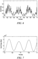
- Figure 6 shows the effect of converting the expanded signal from simple amplitude into sound energy, resulting in a much cleaner wave structure. This can then be filtered to give smooth signal with readily identifiable peaks and troughs as shown in Figure 7 .
- the algorithm can process 20sec of audio feed in only 50msec, which provides a factor of 400 of margin for real time processing. Even when the algorithm is run on a mobile phone or the like the margin is more than sufficient.
- the algorithm operates upon incremental chunks of audio data, typically a new chunk of the latest audio capture every 0.1 or 0.2msec.
- the operating range of the algorithm is configured to 10-40Hz, that is, it aims at detecting a vibration frequency in this range.
- pitch is used to mean the frequency of vibration of the valve in the therapy device after removal of the additional high frequency noise.
- the pitch or frequency detection algorithm and the pitch/pressure model can be implemented in C++, using only core C++ libraries such as vector and string.
- the algorithm processes the audio in incremental chunks of 0.2sec, executes a 20 second audio sample in about 50milliseconds. This provides a performance headroom factor of 400, which provides ample headroom for the code in a mobile phone or similar device.
- constant and factor A and B may be different in different types of oscillatory resistance therapy devices but, in general, it is believed that the same form of relationship will exist.
- the phone or other sensor unit 20 is placed separately and remotely from the device 100 but sufficiently close to the device to be within the audible range of the microphone 21; the sensor unit need not be in direct contact with the device.
- the therapy monitor app in the phone 20 is located and started. When the user starts the therapy session the device 100 starts to emit sound waves that are picked up by the microphone 21 in the phone 20.
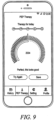
- the pressure is then displayed on the screen 24 of the phone 20, during a therapy session, in a combination of numerical and graphical representations as illustrated in Figure 9 .
- the pressure is represented along a scale with different colours indicating that the pressure is too low, too high or correct.
- the phone screen 24 switches to display a therapy history.
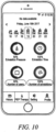
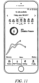
- Two different alternative history representations are illustrated in Figures 10 and 11 , showing typically the average exhalation pressure, the exhalation time, the number of uses over a period (such as each week) and the number of exhalations during the therapy session.
- the setting of the dial 5 on the therapy device 100 affects the frequency and resistance to flow through the device. This is set by the user to achieve the maximum beneficial effect.
- the app in the phone 20 could be arranged to receive a manual input of the dial setting by the user or clinician.
- the sensor means described above is provided by a program or app in the mobile phone 20 but it could, instead, be provided by a dedicated sensor unit with a suitably programmed processor. Such a sensor unit could be mounted with the therapy device, such as by means of a clip or strap that supports the sensor on the device.
- the sensor means could be provided by a multifunction unit such as provided by program application in a general purpose computer, using the microphone built in the computer, or a separate plug-in microphone.
- the program application could be arranged to stop automatically after the elapse of a predetermined time without sensing any sound of the characteristic frequencies.
- Apparatus of the present invention can be used with any conventional respiratory therapy apparatus that produces a sound signal.
- the therapy apparatus may be combined with other treatments such as nebulisation or the administration of aerosol medication.
- the present invention enables someone using an existing, conventional therapy device to be provided with useful data about its use. In this way, the user can be made more aware of how well he is complying with the prescribed therapy programme and can modify his use of the device accordingly to achieve maximum benefit.
- the clinician is also able to check patient compliance so that he can identify whether any deterioration in a patient's condition is due to lack of compliance or if alternative treatment is needed.
Landscapes
- Health & Medical Sciences (AREA)
- Pulmonology (AREA)
- General Health & Medical Sciences (AREA)
- Heart & Thoracic Surgery (AREA)
- Anesthesiology (AREA)
- Biomedical Technology (AREA)
- Engineering & Computer Science (AREA)
- Hematology (AREA)
- Life Sciences & Earth Sciences (AREA)
- Animal Behavior & Ethology (AREA)
- Emergency Medicine (AREA)
- Public Health (AREA)
- Veterinary Medicine (AREA)
- Physical Education & Sports Medicine (AREA)
- Measurement Of The Respiration, Hearing Ability, Form, And Blood Characteristics Of Living Organisms (AREA)
Description
- This invention relates to respiratory therapy apparatus of the kind including a device arranged to provide an alternating resistance to respiratory flow through the device and a sensor unit arranged to sense sound made by the device.
- Positive expiratory pressure (PEP) apparatus, that is, apparatus that presents a resistance to expiration through the device, are now widely used to help treat patients suffering from a range of respiratory impairments, such as chronic obstructive pulmonary disease, bronchitis, cystic fibrosis and atelectasis. More recently, such apparatus that provide an alternating resistance to flow have been found to be particularly effective. One example of such apparatus is sold under the trade mark Acapella (a registered trade mark of Smiths Medical) by Smiths Medical and is described in
US6581598 ,US6776159 ,US7059324 andUS7699054 . Other vibratory respiratory therapy apparatus is available, such as "Quake" manufactured by Thayer, "AeroPEP" manufactured by Monaghan, "TheraPEP" manufactured by Smiths Medical and "IPV Percussionator" manufactured by Percussionaire Corp. Alternative apparatus such as "CoughAssist" manufactured by Philips is also available. Respiratory therapy apparatus can instead provide an alternating resistance to flow during inhalation.WO 14202923 WO14202924 WO16079461 - To be effective these apparatus must be used regularly at prescribed intervals. In the case of chronic diseases, the patient needs to use the apparatus daily for the rest of his life in order to maintain a continuous relief.
- Although these apparatus can be very effective, users often neglect to use the apparatus regularly at the prescribed frequency. It is very difficult to maintain a record of use of the apparatus, especially when the patient is using it at home. The clinician often does not know whether deterioration in a patient's condition is because he has failed to use the apparatus as prescribed or whether other factors are the cause. It can be useful to monitor pressure within the therapy device for the purpose of monitoring use, or in providing feedback to the patient to prompt correct use. It has previously been proposed to mount a pressure sensor in the therapy device to monitor pressure. This, however, adds to cost of what is usually a disposable device and requires electrical power within the device, which can lead to electrical safety concerns or to disposal problems where batteries are used.
- It is an object of the present invention to provide an alternative respiratory therapy apparatus.
- The present invention provides a respiratory therapy apparatus as defined in
claim 1. The apparatus includes a device arranged to provide an alternating-resistance to respiratory flow through the device and a sensor unit arranged to sense sound made by the device. The sensor unit includes a processor arranged to compute a measure of pressure created in the device from a frequency of the sound. The processor is arranged to compute a measure of the pressure by multiplying the detected frequency by a fixed factor and adding to the product a fixed constant. - The factor may be is about 1.119 and the constant may be about -4.659. The processor is preferably arranged to convert the sound signal into a sound energy signal and to use the sound energy signal in the computation of the measure of pressure. The sensor unit preferably includes a microphone responsive to audible sound. The device may include a valve element on a rocker arm that opens and closes an opening during exhalation through the device. The sensor unit is preferably not mounted on the device but is separate from the device. The sensor unit may be provided by a mobile phone including a microphone and a screen, the processor also being provided by the phone.
- Apparatus including a vibratory PEP device will now be described, by way of example, with reference to the accompanying drawings, in which:
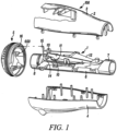
- Figure 1
- is an exploded view of the apparatus;
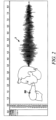
- Figure 2
- illustrates the sound output produced by a single breath;
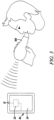
- Figure 3
- illustrates the apparatus in use;
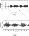
- Figure 4
- is a graph of sound amplitude against time;
- Figure 5
- is a graph of the trace of
Figure 4 over an expanded period of time; - Figure 6
- shows the graph of
Figure 5 converted to sound energy; - Figure 7
- shows the graph of
Figure 6 after filtering; - Figure 8
- is a graph illustrating the relationship between frequency and pressure;
- Figure 9
- shows the screen of a mobile phone during a therapy session; and
- Figures 10 and 11
- show alternative screen displays of the mobile phone after use with different representations of therapy history over a week.
- With reference first to
Figure 1 , thedevice 100 comprises arocker assembly 1 contained within anouter housing 2 provided by anupper part 3 and alower part 4 of substantially semicylindrical shape. The device is completed by anadjustable dial 5 of circular section. Therocker assembly 1 includes an air flow tube 6 with abreathing inlet 7 at one end and an inspiratory inlet 8 at the opposite end including a one-way valve (not shown) that allows air to flow into the air flow tube 6 but prevents air flowing out through the inspiratory inlet. The air flow tube 6 has an outlet opening 10 with a non-linear profile that is opened and closed by aconical valve element 11 mounted on arocker arm 12 pivoted midway along its length about a transverse axis. The air flow tube 6 andhousing 2 provide a structure with which therocker arm 12 is mounted. At its far end, remote from thebreathing inlet 7, therocker arm 12 carries aniron pin 13 that interacts with the magnetic field produced by a permanent magnet (not visible) mounted on anadjustable support frame 14. The magnet arrangement is such that, when the patient is not breathing through the device, the far end of therocker arm 12 is held down such that itsvalve element 11 is also held down in sealing engagement with the outlet opening 10. Acam follower projection 15 at one end of thesupport frame 14 locates in acam slot 16 in thedial 5 such that, by rotating the dial, thesupport frame 14, with its magnet, can be moved up or down to alter the strength of the magnetic field interacting with theiron pin 13. Thedial 5 enables the frequency of operation and the resistance to flow of air through the device to be adjusted for maximum therapeutic benefit to the user. - When the patient inhales through the
breathing inlet 7 air is drawn through the inspiratory inlet 8 and along the air flow tube 6 to the breathing inlet. When the patient exhales, the one-way valve in the inspiratory inlet 8 closes, preventing any air flowing out along this path. Instead, the expiratory pressure is applied to the underside of thevalve element 11 on therocker arm 12 causing it to be lifted up out of the opening 10 against the magnetic attraction, thereby allowing air to flow out to atmosphere. The opening 10 has a non-linear profile, which causes the effective discharge area to increase as the far end of therocker arm 12 lifts, thereby allowing the arm to fall back down and close the opening. As long as the user keeps applying sufficient expiratory pressure, therocker arm 12 will rise and fall repeatedly as theopening 10 is opened and closed, causing a vibratory, alternating or oscillating resistance to expiratory breath flow through the device. This oscillating movement of therocker arm 12 produces a rattling sound audible externally of thetherapy device 2. Further information about the construction and operation of the device can be found inUS6581598 , the contents of which are not essential for an understanding of the present invention. - As so far described, the apparatus is conventional.
- The apparatus of the present invention includes the
device 100 described above and sensor means 20 responsive to pressure waves transmitted through air and caused by use of the device. Typically the pressure waves are at acoustic frequencies, producing an audible sound that can be sensed by a conventional microphone. -
Figure 2 illustrates the patient exhaling through thedevice 100 to produce the desired therapy effect. The oscillating movement of therocker arm 12 produces an audible sound that is transmitted through the surrounding air as pressure waves. This is represented by the trace "T" of a single expiration breath shown at the right of the Figure. It can be seen that the sensed sound takes the form of rapidly alternating positive and negative peaks at a frequency dependent on the frequency of rocking of therocker arm 12 and with a mean amplitude that rises to a maximum towards the start of the breath and then gradually tails off towards the end of the breath. -
Figure 3 shows thedevice 100 and sensor means in the form of amobile phone 20 programmed with an app arranged to process the output of themicrophone 21 in the phone. Thephone 20 thereby provides a stand-alone acoustic sensor that is separate from thedevice 2 but, in use, is placed close to it. Themicrophone 21 in thephone 20 is connected to aprocessor 22 including a memory unit and provides an output to adisplay screen 24. Themicrophone 21 is responsive to sound in the audible hearing range. The app programmed in theprocessor 22 includes a frequency detection algorithm arranged to determine the frequency of the signal from themicrophone 21. - The frequency detection algorithm is arranged to measure the fluttering frequency of the therapy device during operation is based on autocorrelation in the time domain, operating upon a filtered signal that embodies the sound energy rather than the sound amplitude. Sound energy is dependent on sound amplitude and on the frequency of the sound and has been found to give a clearer representation of wave structure.
-
Figures 4 shows the detected audio signal from the therapy device andFigure 5 shows this signal expanded over a shorter time period. It can be seen that, although the frequency or pitch pattern is identifiable it is confused by the high frequency signal overlaid on top of this.Figure 6 shows the effect of converting the expanded signal from simple amplitude into sound energy, resulting in a much cleaner wave structure. This can then be filtered to give smooth signal with readily identifiable peaks and troughs as shown inFigure 7 . - In the algorithm equal emphasis is placed on accuracy and computational speed. For example, when implemented in C++ the algorithm can process 20sec of audio feed in only 50msec, which provides a factor of 400 of margin for real time processing. Even when the algorithm is run on a mobile phone or the like the margin is more than sufficient. The algorithm operates upon incremental chunks of audio data, typically a new chunk of the latest audio capture every 0.1 or 0.2msec. The operating range of the algorithm is configured to 10-40Hz, that is, it aims at detecting a vibration frequency in this range.
- More details of the frequency detection algorithm are given below in which the term pitch is used to mean the frequency of vibration of the valve in the therapy device after removal of the additional high frequency noise.
- A target range of the pitch is defined as: [flower fupper] = [10Hz 40Hz]
- The audio signal, which comes at FS = 48kHz or 44.1kHz, is downsampled by a factor 45 (to 980Hz). The downsampling rate is arrived at by setting the desired pitch accuracy at 2.5% in the middle of the frequency range
- From the raw audio signal a smoothed version is subtracted.
- The smoothed version is computed by averaging over a neighborhood equal to the length of the smallest formant frequency (this is the typical natural frequency generated within the therapy device, starting at 250Hz and up) 176 audio sample points
- After the subtraction, compute the square
- Downsample the signal by averaging contiguous sets of 45 samples (no overlap)
- This downsampled signal is referred to as the audio energy
- A smoothed version of the audio energy is computed by convolving with a filter, which is a Gaussian with sigma = 0.2*45*fupper/Fs. This means the FWHM of the Gaussian is 0.4 times the period of the highest pitch frequency sought. If one goes much larger, it will start to blur out the pitch signature in the upper range (40Hz).
- As chunks of audio become available, they are processed in a pipeline that keeps track of previous moving averages.
- In the smoothed signal the autocorrelation is computed in an economical fashion:
- o Once a pitch has been detected, the next autocorrelation is computed at a location one wavelength (of the last pitch detected) ahead of the previous point
- ∘ A target range for the pitch is maintained so that autocorrelation computation is focused in the most likely locations
- ∘ The time resolution of the autocorrelation is rough in the first calculation, then finer resolution is done around the maxima
- Pick the argmax of the autocorrelation function, provided that the correlation is greater than 0.6:
- ∘ Update the moving average value for the pitch with the pitch corresponding to the argmax value
- ∘ Update the derivative of the moving average, in order to refine the search window at the next iteration
- Update a run length for pitch detection:
- ∘ The run length is initialized to 0
- o Every time a pitch has been positively identified, the run length is incremented by 1, unless:
- The run length has reached a maximum, which is given by a decay rate as round(1 - 1/decayRate). In our case, decay rate is set to 0.8, which gives a max run rate of 5
- o If from one detected autocorrelation (>0.6) value to the next, the leap exceeds the expected amount, as given by the running average value for pitch, the run rate is reduced by the equivalent number
- Compute the mix value a: mix = min([decayRate 1 - 1/runlength])
- Update the moving average values for, period (1/pitch), amplitude, derivative
-
- Compute pitch or frequency as: Pitch = 1/(movingAvePeriod)
- The pitch or frequency detection algorithm and the pitch/pressure model can be implemented in C++, using only core C++ libraries such as vector and string. When the algorithm processes the audio in incremental chunks of 0.2sec, executes a 20 second audio sample in about 50milliseconds. This provides a performance headroom factor of 400, which provides ample headroom for the code in a mobile phone or similar device.
- From extensive experimental data it has been found that the frequency of vibration of the
rocker arm 12 andvalve element 11 that provides the oscillating resistance to flow is closely related in a linear fashion to pressure measured inside the air flow tube 6. This is illustrated in the graph shown inFigure 8 . Using a linear model this produces an r2 of 0.886 over 9993 data points, which is a very good fit. Similar results were found to apply regardless of the setting of theresistance dial 5. - The relationship between detected frequency and pressure can be expressed in the form:

- Where P is pressure in cm of water, f is frequency, A is a constant and B is a constant factor.
- More particularly, for the
respiratory therapy device 2 described above it has been found that:
- It will be appreciated that the constant and factor A and B may be different in different types of oscillatory resistance therapy devices but, in general, it is believed that the same form of relationship will exist.
- The importance of this is that it means that it is possible to obtain a very close indication of the pressure within the therapy device solely from its detected frequency of operation and without the need for any dedicated pressure sensor within the device.
- In this way it is possible to derive an accurate indication of pressure from an unmodified therapy device. By avoiding the need to mount a pressure sensor in the therapy device it helps keep its cost to a minimum. It also avoids the need for any electrical supply to or within the therapy device. This in turn avoids any need to make special provision to provide electrical safety isolation in the device and avoids the need for cables extending to and from the device. It also avoids the needs for batteries in the device, which can present transport safety problems, which require special measures to ensure they do not exceed a safe storage time, and which present various disposal problems.
- In use, the phone or
other sensor unit 20 is placed separately and remotely from thedevice 100 but sufficiently close to the device to be within the audible range of themicrophone 21; the sensor unit need not be in direct contact with the device. The therapy monitor app in thephone 20 is located and started. When the user starts the therapy session thedevice 100 starts to emit sound waves that are picked up by themicrophone 21 in thephone 20. Theprocessor 22 in thephone 20 carries out the frequency detection algorithm to identify a frequency value and then uses this in the expression: P = -4.659 + 1.119 × f to derive a measure of the pressure in cm of water. This measure of pressure is compared with preprogramed pressure values stored in theprocessor 22 representative of target values and limits appropriate for the particular user. The pressure is then displayed on thescreen 24 of thephone 20, during a therapy session, in a combination of numerical and graphical representations as illustrated inFigure 9 . Typically the pressure is represented along a scale with different colours indicating that the pressure is too low, too high or correct. After the conclusion of the therapy session thephone screen 24 switches to display a therapy history. Two different alternative history representations are illustrated inFigures 10 and11 , showing typically the average exhalation pressure, the exhalation time, the number of uses over a period (such as each week) and the number of exhalations during the therapy session. - As mentioned above, the setting of the
dial 5 on thetherapy device 100 affects the frequency and resistance to flow through the device. This is set by the user to achieve the maximum beneficial effect. The app in thephone 20 could be arranged to receive a manual input of the dial setting by the user or clinician. - The sensor means described above is provided by a program or app in the
mobile phone 20 but it could, instead, be provided by a dedicated sensor unit with a suitably programmed processor. Such a sensor unit could be mounted with the therapy device, such as by means of a clip or strap that supports the sensor on the device. The sensor means could be provided by a multifunction unit such as provided by program application in a general purpose computer, using the microphone built in the computer, or a separate plug-in microphone. The program application could be arranged to stop automatically after the elapse of a predetermined time without sensing any sound of the characteristic frequencies. - It will be appreciated that there are many different ways in which information obtained by the sensor unit can be represented so that it is provided to the user and clinician in the most useful manner.
- Apparatus of the present invention can be used with any conventional respiratory therapy apparatus that produces a sound signal. The therapy apparatus may be combined with other treatments such as nebulisation or the administration of aerosol medication.
- The present invention enables someone using an existing, conventional therapy device to be provided with useful data about its use. In this way, the user can be made more aware of how well he is complying with the prescribed therapy programme and can modify his use of the device accordingly to achieve maximum benefit. The clinician is also able to check patient compliance so that he can identify whether any deterioration in a patient's condition is due to lack of compliance or if alternative treatment is needed.

Claims (8)
- Respiratory therapy apparatus including a device (100) arranged to provide an alternating resistance to respiratory flow through the device and a sensor unit (20) arranged to sense sound made by the device, characterised in that the sensor unit (20) includes a processor (22) arranged to compute a measure of pressure created in the device (100) from a frequency of the sound by multiplying the detected frequency by a fixed factor and adding to the product a fixed constant.
- Apparatus according to Claim 1, characterised in that the factor is about 1.119.
- Apparatus according to Claim 1 or 2, characterised in that the constant is about -4.659.
- Apparatus according to any one of the preceding claims, characterised in that the processor (22) is arranged to convert the sound signal into a sound energy signal and to use the sound energy signal in the computation of the measure of pressure.
- Apparatus according to any one of the preceding claims, characterised in that the sensor unit (20) includes a microphone (21) responsive to audible sound.
- Apparatus according to any one of the preceding claims, characterised in that the device (100) includes a valve element (11) on a rocker arm (12) that opens and closes an opening (10) during exhalation through the device.
- Apparatus according to any one of the preceding claims, characterised in that the sensor unit (20) is not mounted on the device (100) but is separate from the device.
- Apparatus according to Claim 7, characterised in that the sensor unit is provided by a mobile phone (20) including a microphone (21) and a screen (24), and that the processor (22) is also provided by the phone.
Applications Claiming Priority (2)
| Application Number | Priority Date | Filing Date | Title |
|---|---|---|---|
| GBGB1809559.6A GB201809559D0 (en) | 2018-06-09 | 2018-06-09 | Respiratory therapy apparatus and methods |
| PCT/GB2019/000081 WO2019234380A1 (en) | 2018-06-09 | 2019-06-03 | Respiratory therapy apparatus and methods |
Publications (2)
| Publication Number | Publication Date |
|---|---|
| EP3801722A1 EP3801722A1 (en) | 2021-04-14 |
| EP3801722B1 true EP3801722B1 (en) | 2023-05-17 |
Family
ID=62975508
Family Applications (1)
| Application Number | Title | Priority Date | Filing Date |
|---|---|---|---|
| EP19730409.0A Active EP3801722B1 (en) | 2018-06-09 | 2019-06-03 | Respiratory therapy apparatus |
Country Status (5)
| Country | Link |
|---|---|
| US (1) | US12527929B2 (en) |
| EP (1) | EP3801722B1 (en) |
| JP (1) | JP2021525617A (en) |
| GB (1) | GB201809559D0 (en) |
| WO (1) | WO2019234380A1 (en) |
Family Cites Families (19)
| Publication number | Priority date | Publication date | Assignee | Title |
|---|---|---|---|---|
| US6581598B1 (en) | 1999-11-24 | 2003-06-24 | Dhd Healthcare Corporation | Positive expiratory pressure device |
| US7059324B2 (en) | 1999-11-24 | 2006-06-13 | Smiths Medical Asd, Inc. | Positive expiratory pressure device with bypass |
| US6776159B2 (en) * | 1999-11-24 | 2004-08-17 | Dhd Healthcare Corporation | Positive expiratory pressure device with bypass |
| KR100634523B1 (en) * | 2004-11-06 | 2006-10-16 | 삼성전자주식회사 | Exercise motion monitoring device and method |
| US20050255874A1 (en) * | 2005-04-26 | 2005-11-17 | Marie Stewart-Baxter | Motion disabled cell phone method |
| GB201310824D0 (en) | 2013-06-18 | 2013-07-31 | Smiths Medical Int Ltd | Respiratory therapy apparatus and methods |
| GB201310826D0 (en) * | 2013-06-18 | 2013-07-31 | Smiths Medical Int Ltd | Respiratory therapy apparatus and methods |
| WO2014202823A1 (en) | 2013-06-19 | 2014-12-24 | Wärtsilä Finland Oy | Slewing seal arrangement for a steerable thruster |
| CA2917443A1 (en) * | 2013-07-12 | 2015-01-15 | Stephen J. Farr | Acoustic based drug delivery monitor |
| GB201312934D0 (en) * | 2013-07-19 | 2013-09-04 | Smiths Medical Int Ltd | Respiratory therapy apparatus, sensors and methods |
| GB201316223D0 (en) * | 2013-09-12 | 2013-10-30 | Smiths Medical Int Ltd | Respiratory therapy apparatus and methods |
| GB201400188D0 (en) * | 2014-01-07 | 2014-02-26 | Smiths Medical Int Ltd | Respiratory therapy apparatus |
| GB201401566D0 (en) * | 2014-01-30 | 2014-03-19 | Smiths Medical Int Ltd | Respiratory therapy systems, sensors and methods |
| GB201420127D0 (en) * | 2014-11-12 | 2014-12-24 | Smiths Medical Int Ltd | Respiratory therapy apparatus |
| GB201420518D0 (en) * | 2014-11-19 | 2014-12-31 | Smiths Medical Int Ltd | Respiratory therapy apparatus |
| US20170228698A1 (en) * | 2016-02-10 | 2017-08-10 | Mastercard International Incorporated | System and method for benefit distribution with improved proof-of-life features |
| WO2017178776A1 (en) * | 2016-04-14 | 2017-10-19 | Smiths Medical International Limited | Respiratory therapy devices |
| GB201608128D0 (en) * | 2016-05-07 | 2016-06-22 | Smiths Medical Int Ltd | Respiratory monitoring apparatus |
| ES2988939T3 (en) * | 2016-07-08 | 2024-11-22 | Trudell Medical Int Inc | Intelligent Oscillating Positive Expiratory Pressure Device |
-
2018
- 2018-06-09 GB GBGB1809559.6A patent/GB201809559D0/en not_active Ceased
-
2019
- 2019-06-03 JP JP2020568445A patent/JP2021525617A/en active Pending
- 2019-06-03 EP EP19730409.0A patent/EP3801722B1/en active Active
- 2019-06-03 WO PCT/GB2019/000081 patent/WO2019234380A1/en not_active Ceased
- 2019-06-03 US US17/057,175 patent/US12527929B2/en active Active
Also Published As
| Publication number | Publication date |
|---|---|
| GB201809559D0 (en) | 2018-07-25 |
| WO2019234380A1 (en) | 2019-12-12 |
| JP2021525617A (en) | 2021-09-27 |
| US12527929B2 (en) | 2026-01-20 |
| EP3801722A1 (en) | 2021-04-14 |
| US20210228826A1 (en) | 2021-07-29 |
Similar Documents
| Publication | Publication Date | Title |
|---|---|---|
| US20240408331A1 (en) | Respiratory therapy apparatus and methods | |
| EP1701756B1 (en) | Macro-control of treatment for sleep disordered breathing | |
| CN101972505B (en) | Computer controlled CPAP system with snore detection | |
| CN108245131B (en) | Detecting mouth breathing in early expiration | |
| US11464924B2 (en) | Respiratory therapy apparatus | |
| EP2654867B1 (en) | System for inexsufflating a subject | |
| CA3118956C (en) | Method and apparatus for continuous management of airway pressure for detection and/or prediction of respiratory failure | |
| WO2015114285A1 (en) | Respiratory therapy systems, sensors arrangements and methods | |
| EP4226389A1 (en) | Automatic user interface identification | |
| US12527929B2 (en) | Respiratory therapy apparatus and methods | |
| WO2021250573A1 (en) | Acoustic detection of water level in humidifier | |
| EP3946530B1 (en) | Respiratory therapy apparatus | |
| CN113975563A (en) | Breathing machine control method based on snore sound recognition and breathing machine | |
| CN121583274A (en) | A speaking valve and its processing system and method |
Legal Events
| Date | Code | Title | Description |
|---|---|---|---|
| STAA | Information on the status of an ep patent application or granted ep patent |
Free format text: STATUS: UNKNOWN |
|
| STAA | Information on the status of an ep patent application or granted ep patent |
Free format text: STATUS: THE INTERNATIONAL PUBLICATION HAS BEEN MADE |
|
| PUAI | Public reference made under article 153(3) epc to a published international application that has entered the european phase |
Free format text: ORIGINAL CODE: 0009012 |
|
| STAA | Information on the status of an ep patent application or granted ep patent |
Free format text: STATUS: REQUEST FOR EXAMINATION WAS MADE |
|
| 17P | Request for examination filed |
Effective date: 20201028 |
|
| AK | Designated contracting states |
Kind code of ref document: A1 Designated state(s): AL AT BE BG CH CY CZ DE DK EE ES FI FR GB GR HR HU IE IS IT LI LT LU LV MC MK MT NL NO PL PT RO RS SE SI SK SM TR |
|
| AX | Request for extension of the european patent |
Extension state: BA ME |
|
| DAV | Request for validation of the european patent (deleted) | ||
| DAX | Request for extension of the european patent (deleted) | ||
| REG | Reference to a national code |
Ref country code: DE Free format text: PREVIOUS MAIN CLASS: A61M0016200000 Ref country code: DE Ref legal event code: R079 Ref document number: 602019029076 Country of ref document: DE Free format text: PREVIOUS MAIN CLASS: A61M0016200000 Ipc: A61M0016000000 |
|
| GRAP | Despatch of communication of intention to grant a patent |
Free format text: ORIGINAL CODE: EPIDOSNIGR1 |
|
| STAA | Information on the status of an ep patent application or granted ep patent |
Free format text: STATUS: GRANT OF PATENT IS INTENDED |
|
| RIC1 | Information provided on ipc code assigned before grant |
Ipc: A61M 16/20 20060101ALI20221011BHEP Ipc: A61M 16/00 20060101AFI20221011BHEP |
|
| INTG | Intention to grant announced |
Effective date: 20221107 |
|
| GRAS | Grant fee paid |
Free format text: ORIGINAL CODE: EPIDOSNIGR3 |
|
| RIN1 | Information on inventor provided before grant (corrected) |
Inventor name: SKATTER, SONDRE Inventor name: KHASAWNEH, MOHAMMAD QASSIM MOHAMMAD |
|
| GRAA | (expected) grant |
Free format text: ORIGINAL CODE: 0009210 |
|
| STAA | Information on the status of an ep patent application or granted ep patent |
Free format text: STATUS: THE PATENT HAS BEEN GRANTED |
|
| AK | Designated contracting states |
Kind code of ref document: B1 Designated state(s): AL AT BE BG CH CY CZ DE DK EE ES FI FR GB GR HR HU IE IS IT LI LT LU LV MC MK MT NL NO PL PT RO RS SE SI SK SM TR |
|
| REG | Reference to a national code |
Ref country code: GB Ref legal event code: FG4D |
|
| REG | Reference to a national code |
Ref country code: CH Ref legal event code: EP |
|
| REG | Reference to a national code |
Ref country code: DE Ref legal event code: R096 Ref document number: 602019029076 Country of ref document: DE |
|
| REG | Reference to a national code |
Ref country code: IE Ref legal event code: FG4D |
|
| P01 | Opt-out of the competence of the unified patent court (upc) registered |
Effective date: 20230419 |
|
| REG | Reference to a national code |
Ref country code: AT Ref legal event code: REF Ref document number: 1568170 Country of ref document: AT Kind code of ref document: T Effective date: 20230615 |
|
| REG | Reference to a national code |
Ref country code: LT Ref legal event code: MG9D |
|
| REG | Reference to a national code |
Ref country code: NL Ref legal event code: MP Effective date: 20230517 |
|
| REG | Reference to a national code |
Ref country code: AT Ref legal event code: MK05 Ref document number: 1568170 Country of ref document: AT Kind code of ref document: T Effective date: 20230517 |
|
| PG25 | Lapsed in a contracting state [announced via postgrant information from national office to epo] |
Ref country code: SE Free format text: LAPSE BECAUSE OF FAILURE TO SUBMIT A TRANSLATION OF THE DESCRIPTION OR TO PAY THE FEE WITHIN THE PRESCRIBED TIME-LIMIT Effective date: 20230517 Ref country code: PT Free format text: LAPSE BECAUSE OF FAILURE TO SUBMIT A TRANSLATION OF THE DESCRIPTION OR TO PAY THE FEE WITHIN THE PRESCRIBED TIME-LIMIT Effective date: 20230918 Ref country code: NO Free format text: LAPSE BECAUSE OF FAILURE TO SUBMIT A TRANSLATION OF THE DESCRIPTION OR TO PAY THE FEE WITHIN THE PRESCRIBED TIME-LIMIT Effective date: 20230817 Ref country code: NL Free format text: LAPSE BECAUSE OF FAILURE TO SUBMIT A TRANSLATION OF THE DESCRIPTION OR TO PAY THE FEE WITHIN THE PRESCRIBED TIME-LIMIT Effective date: 20230517 Ref country code: ES Free format text: LAPSE BECAUSE OF FAILURE TO SUBMIT A TRANSLATION OF THE DESCRIPTION OR TO PAY THE FEE WITHIN THE PRESCRIBED TIME-LIMIT Effective date: 20230517 Ref country code: AT Free format text: LAPSE BECAUSE OF FAILURE TO SUBMIT A TRANSLATION OF THE DESCRIPTION OR TO PAY THE FEE WITHIN THE PRESCRIBED TIME-LIMIT Effective date: 20230517 |
|
| PG25 | Lapsed in a contracting state [announced via postgrant information from national office to epo] |
Ref country code: RS Free format text: LAPSE BECAUSE OF FAILURE TO SUBMIT A TRANSLATION OF THE DESCRIPTION OR TO PAY THE FEE WITHIN THE PRESCRIBED TIME-LIMIT Effective date: 20230517 Ref country code: PL Free format text: LAPSE BECAUSE OF FAILURE TO SUBMIT A TRANSLATION OF THE DESCRIPTION OR TO PAY THE FEE WITHIN THE PRESCRIBED TIME-LIMIT Effective date: 20230517 Ref country code: LV Free format text: LAPSE BECAUSE OF FAILURE TO SUBMIT A TRANSLATION OF THE DESCRIPTION OR TO PAY THE FEE WITHIN THE PRESCRIBED TIME-LIMIT Effective date: 20230517 Ref country code: LT Free format text: LAPSE BECAUSE OF FAILURE TO SUBMIT A TRANSLATION OF THE DESCRIPTION OR TO PAY THE FEE WITHIN THE PRESCRIBED TIME-LIMIT Effective date: 20230517 Ref country code: IS Free format text: LAPSE BECAUSE OF FAILURE TO SUBMIT A TRANSLATION OF THE DESCRIPTION OR TO PAY THE FEE WITHIN THE PRESCRIBED TIME-LIMIT Effective date: 20230917 Ref country code: HR Free format text: LAPSE BECAUSE OF FAILURE TO SUBMIT A TRANSLATION OF THE DESCRIPTION OR TO PAY THE FEE WITHIN THE PRESCRIBED TIME-LIMIT Effective date: 20230517 Ref country code: GR Free format text: LAPSE BECAUSE OF FAILURE TO SUBMIT A TRANSLATION OF THE DESCRIPTION OR TO PAY THE FEE WITHIN THE PRESCRIBED TIME-LIMIT Effective date: 20230818 |
|
| PG25 | Lapsed in a contracting state [announced via postgrant information from national office to epo] |
Ref country code: FI Free format text: LAPSE BECAUSE OF FAILURE TO SUBMIT A TRANSLATION OF THE DESCRIPTION OR TO PAY THE FEE WITHIN THE PRESCRIBED TIME-LIMIT Effective date: 20230517 |
|
| PG25 | Lapsed in a contracting state [announced via postgrant information from national office to epo] |
Ref country code: SK Free format text: LAPSE BECAUSE OF FAILURE TO SUBMIT A TRANSLATION OF THE DESCRIPTION OR TO PAY THE FEE WITHIN THE PRESCRIBED TIME-LIMIT Effective date: 20230517 |
|
| PG25 | Lapsed in a contracting state [announced via postgrant information from national office to epo] |
Ref country code: SM Free format text: LAPSE BECAUSE OF FAILURE TO SUBMIT A TRANSLATION OF THE DESCRIPTION OR TO PAY THE FEE WITHIN THE PRESCRIBED TIME-LIMIT Effective date: 20230517 Ref country code: SK Free format text: LAPSE BECAUSE OF FAILURE TO SUBMIT A TRANSLATION OF THE DESCRIPTION OR TO PAY THE FEE WITHIN THE PRESCRIBED TIME-LIMIT Effective date: 20230517 Ref country code: RO Free format text: LAPSE BECAUSE OF FAILURE TO SUBMIT A TRANSLATION OF THE DESCRIPTION OR TO PAY THE FEE WITHIN THE PRESCRIBED TIME-LIMIT Effective date: 20230517 Ref country code: EE Free format text: LAPSE BECAUSE OF FAILURE TO SUBMIT A TRANSLATION OF THE DESCRIPTION OR TO PAY THE FEE WITHIN THE PRESCRIBED TIME-LIMIT Effective date: 20230517 Ref country code: DK Free format text: LAPSE BECAUSE OF FAILURE TO SUBMIT A TRANSLATION OF THE DESCRIPTION OR TO PAY THE FEE WITHIN THE PRESCRIBED TIME-LIMIT Effective date: 20230517 Ref country code: CZ Free format text: LAPSE BECAUSE OF FAILURE TO SUBMIT A TRANSLATION OF THE DESCRIPTION OR TO PAY THE FEE WITHIN THE PRESCRIBED TIME-LIMIT Effective date: 20230517 |
|
| REG | Reference to a national code |
Ref country code: CH Ref legal event code: PL |
|
| REG | Reference to a national code |
Ref country code: DE Ref legal event code: R097 Ref document number: 602019029076 Country of ref document: DE |
|
| REG | Reference to a national code |
Ref country code: BE Ref legal event code: MM Effective date: 20230630 |
|
| PG25 | Lapsed in a contracting state [announced via postgrant information from national office to epo] |
Ref country code: MC Free format text: LAPSE BECAUSE OF FAILURE TO SUBMIT A TRANSLATION OF THE DESCRIPTION OR TO PAY THE FEE WITHIN THE PRESCRIBED TIME-LIMIT Effective date: 20230517 |
|
| PG25 | Lapsed in a contracting state [announced via postgrant information from national office to epo] |
Ref country code: MC Free format text: LAPSE BECAUSE OF FAILURE TO SUBMIT A TRANSLATION OF THE DESCRIPTION OR TO PAY THE FEE WITHIN THE PRESCRIBED TIME-LIMIT Effective date: 20230517 |
|
| PG25 | Lapsed in a contracting state [announced via postgrant information from national office to epo] |
Ref country code: LU Free format text: LAPSE BECAUSE OF NON-PAYMENT OF DUE FEES Effective date: 20230603 |
|
| PLBE | No opposition filed within time limit |
Free format text: ORIGINAL CODE: 0009261 |
|
| STAA | Information on the status of an ep patent application or granted ep patent |
Free format text: STATUS: NO OPPOSITION FILED WITHIN TIME LIMIT |
|
| REG | Reference to a national code |
Ref country code: IE Ref legal event code: MM4A |
|
| PG25 | Lapsed in a contracting state [announced via postgrant information from national office to epo] |
Ref country code: LU Free format text: LAPSE BECAUSE OF NON-PAYMENT OF DUE FEES Effective date: 20230603 |
|
| PG25 | Lapsed in a contracting state [announced via postgrant information from national office to epo] |
Ref country code: IE Free format text: LAPSE BECAUSE OF NON-PAYMENT OF DUE FEES Effective date: 20230603 |
|
| 26N | No opposition filed |
Effective date: 20240220 |
|
| PG25 | Lapsed in a contracting state [announced via postgrant information from national office to epo] |
Ref country code: IE Free format text: LAPSE BECAUSE OF NON-PAYMENT OF DUE FEES Effective date: 20230603 Ref country code: CH Free format text: LAPSE BECAUSE OF NON-PAYMENT OF DUE FEES Effective date: 20230630 |
|
| PG25 | Lapsed in a contracting state [announced via postgrant information from national office to epo] |
Ref country code: SI Free format text: LAPSE BECAUSE OF FAILURE TO SUBMIT A TRANSLATION OF THE DESCRIPTION OR TO PAY THE FEE WITHIN THE PRESCRIBED TIME-LIMIT Effective date: 20230517 |
|
| PG25 | Lapsed in a contracting state [announced via postgrant information from national office to epo] |
Ref country code: SI Free format text: LAPSE BECAUSE OF FAILURE TO SUBMIT A TRANSLATION OF THE DESCRIPTION OR TO PAY THE FEE WITHIN THE PRESCRIBED TIME-LIMIT Effective date: 20230517 Ref country code: IT Free format text: LAPSE BECAUSE OF FAILURE TO SUBMIT A TRANSLATION OF THE DESCRIPTION OR TO PAY THE FEE WITHIN THE PRESCRIBED TIME-LIMIT Effective date: 20230517 Ref country code: BE Free format text: LAPSE BECAUSE OF NON-PAYMENT OF DUE FEES Effective date: 20230630 |
|
| PG25 | Lapsed in a contracting state [announced via postgrant information from national office to epo] |
Ref country code: BG Free format text: LAPSE BECAUSE OF FAILURE TO SUBMIT A TRANSLATION OF THE DESCRIPTION OR TO PAY THE FEE WITHIN THE PRESCRIBED TIME-LIMIT Effective date: 20230517 |
|
| REG | Reference to a national code |
Ref country code: DE Ref legal event code: R081 Ref document number: 602019029076 Country of ref document: DE Owner name: ICU MEDICAL INTERNATIONAL LTD., ASHFORD, GB Free format text: FORMER OWNER: SMITHS MEDICAL INTERNATIONAL LTD., ASHFORD, KENT, GB |
|
| PG25 | Lapsed in a contracting state [announced via postgrant information from national office to epo] |
Ref country code: BG Free format text: LAPSE BECAUSE OF FAILURE TO SUBMIT A TRANSLATION OF THE DESCRIPTION OR TO PAY THE FEE WITHIN THE PRESCRIBED TIME-LIMIT Effective date: 20230517 |
|
| PG25 | Lapsed in a contracting state [announced via postgrant information from national office to epo] |
Ref country code: CY Free format text: LAPSE BECAUSE OF FAILURE TO SUBMIT A TRANSLATION OF THE DESCRIPTION OR TO PAY THE FEE WITHIN THE PRESCRIBED TIME-LIMIT; INVALID AB INITIO Effective date: 20190603 |
|
| PG25 | Lapsed in a contracting state [announced via postgrant information from national office to epo] |
Ref country code: HU Free format text: LAPSE BECAUSE OF FAILURE TO SUBMIT A TRANSLATION OF THE DESCRIPTION OR TO PAY THE FEE WITHIN THE PRESCRIBED TIME-LIMIT; INVALID AB INITIO Effective date: 20190603 |
|
| PG25 | Lapsed in a contracting state [announced via postgrant information from national office to epo] |
Ref country code: TR Free format text: LAPSE BECAUSE OF FAILURE TO SUBMIT A TRANSLATION OF THE DESCRIPTION OR TO PAY THE FEE WITHIN THE PRESCRIBED TIME-LIMIT Effective date: 20230517 |
|
| PGFP | Annual fee paid to national office [announced via postgrant information from national office to epo] |
Ref country code: GB Payment date: 20260408 Year of fee payment: 8 |
|
| PGFP | Annual fee paid to national office [announced via postgrant information from national office to epo] |
Ref country code: DE Payment date: 20260331 Year of fee payment: 8 |
|
| PGFP | Annual fee paid to national office [announced via postgrant information from national office to epo] |
Ref country code: FR Payment date: 20260401 Year of fee payment: 8 |