EP3800895A1 - Video monitoring method, video monitoring device, and video monitoring system - Google Patents
Video monitoring method, video monitoring device, and video monitoring system Download PDFInfo
- Publication number
- EP3800895A1 EP3800895A1 EP20195477.3A EP20195477A EP3800895A1 EP 3800895 A1 EP3800895 A1 EP 3800895A1 EP 20195477 A EP20195477 A EP 20195477A EP 3800895 A1 EP3800895 A1 EP 3800895A1
- Authority
- EP
- European Patent Office
- Prior art keywords
- display device
- power consumption
- video monitoring
- content
- predetermined
- Prior art date
- Legal status (The legal status is an assumption and is not a legal conclusion. Google has not performed a legal analysis and makes no representation as to the accuracy of the status listed.)
- Granted
Links
Images





Classifications
-
- G—PHYSICS
- G09—EDUCATION; CRYPTOGRAPHY; DISPLAY; ADVERTISING; SEALS
- G09G—ARRANGEMENTS OR CIRCUITS FOR CONTROL OF INDICATING DEVICES USING STATIC MEANS TO PRESENT VARIABLE INFORMATION
- G09G3/00—Control arrangements or circuits, of interest only in connection with visual indicators other than cathode-ray tubes
- G09G3/20—Control arrangements or circuits, of interest only in connection with visual indicators other than cathode-ray tubes for presentation of an assembly of a number of characters, e.g. a page, by composing the assembly by combination of individual elements arranged in a matrix no fixed position being assigned to or needed to be assigned to the individual characters or partial characters
- G09G3/34—Control arrangements or circuits, of interest only in connection with visual indicators other than cathode-ray tubes for presentation of an assembly of a number of characters, e.g. a page, by composing the assembly by combination of individual elements arranged in a matrix no fixed position being assigned to or needed to be assigned to the individual characters or partial characters by control of light from an independent source
- G09G3/3406—Control of illumination source
-
- H—ELECTRICITY
- H04—ELECTRIC COMMUNICATION TECHNIQUE
- H04N—PICTORIAL COMMUNICATION, e.g. TELEVISION
- H04N21/00—Selective content distribution, e.g. interactive television or video on demand [VOD]
- H04N21/20—Servers specifically adapted for the distribution of content, e.g. VOD servers; Operations thereof
- H04N21/25—Management operations performed by the server for facilitating the content distribution or administrating data related to end-users or client devices, e.g. end-user or client device authentication, learning user preferences for recommending movies
- H04N21/258—Client or end-user data management, e.g. managing client capabilities, user preferences or demographics, processing of multiple end-users preferences to derive collaborative data
-
- G—PHYSICS
- G09—EDUCATION; CRYPTOGRAPHY; DISPLAY; ADVERTISING; SEALS
- G09G—ARRANGEMENTS OR CIRCUITS FOR CONTROL OF INDICATING DEVICES USING STATIC MEANS TO PRESENT VARIABLE INFORMATION
- G09G3/00—Control arrangements or circuits, of interest only in connection with visual indicators other than cathode-ray tubes
- G09G3/006—Electronic inspection or testing of displays and display drivers, e.g. of LED or LCD displays
-
- H—ELECTRICITY
- H04—ELECTRIC COMMUNICATION TECHNIQUE
- H04N—PICTORIAL COMMUNICATION, e.g. TELEVISION
- H04N21/00—Selective content distribution, e.g. interactive television or video on demand [VOD]
- H04N21/40—Client devices specifically adapted for the reception of or interaction with content, e.g. set-top-box [STB]; Operations thereof
- H04N21/43—Processing of content or additional data, e.g. demultiplexing additional data from a digital video stream; Elementary client operations, e.g. monitoring of home network or synchronising decoder's clock; Client middleware
- H04N21/442—Monitoring of processes or resources, e.g. detecting the failure of a recording device, monitoring the downstream bandwidth, the number of times a movie has been viewed, the storage space available from the internal hard disk
-
- H—ELECTRICITY
- H04—ELECTRIC COMMUNICATION TECHNIQUE
- H04N—PICTORIAL COMMUNICATION, e.g. TELEVISION
- H04N21/00—Selective content distribution, e.g. interactive television or video on demand [VOD]
- H04N21/40—Client devices specifically adapted for the reception of or interaction with content, e.g. set-top-box [STB]; Operations thereof
- H04N21/43—Processing of content or additional data, e.g. demultiplexing additional data from a digital video stream; Elementary client operations, e.g. monitoring of home network or synchronising decoder's clock; Client middleware
- H04N21/442—Monitoring of processes or resources, e.g. detecting the failure of a recording device, monitoring the downstream bandwidth, the number of times a movie has been viewed, the storage space available from the internal hard disk
- H04N21/44204—Monitoring of content usage, e.g. the number of times a movie has been viewed, copied or the amount which has been watched
-
- H—ELECTRICITY
- H04—ELECTRIC COMMUNICATION TECHNIQUE
- H04N—PICTORIAL COMMUNICATION, e.g. TELEVISION
- H04N21/00—Selective content distribution, e.g. interactive television or video on demand [VOD]
- H04N21/40—Client devices specifically adapted for the reception of or interaction with content, e.g. set-top-box [STB]; Operations thereof
- H04N21/43—Processing of content or additional data, e.g. demultiplexing additional data from a digital video stream; Elementary client operations, e.g. monitoring of home network or synchronising decoder's clock; Client middleware
- H04N21/442—Monitoring of processes or resources, e.g. detecting the failure of a recording device, monitoring the downstream bandwidth, the number of times a movie has been viewed, the storage space available from the internal hard disk
- H04N21/4424—Monitoring of the internal components or processes of the client device, e.g. CPU or memory load, processing speed, timer, counter or percentage of the hard disk space used
-
- G—PHYSICS
- G09—EDUCATION; CRYPTOGRAPHY; DISPLAY; ADVERTISING; SEALS
- G09G—ARRANGEMENTS OR CIRCUITS FOR CONTROL OF INDICATING DEVICES USING STATIC MEANS TO PRESENT VARIABLE INFORMATION
- G09G2330/00—Aspects of power supply; Aspects of display protection and defect management
- G09G2330/02—Details of power systems and of start or stop of display operation
- G09G2330/021—Power management, e.g. power saving
-
- G—PHYSICS
- G09—EDUCATION; CRYPTOGRAPHY; DISPLAY; ADVERTISING; SEALS
- G09G—ARRANGEMENTS OR CIRCUITS FOR CONTROL OF INDICATING DEVICES USING STATIC MEANS TO PRESENT VARIABLE INFORMATION
- G09G2360/00—Aspects of the architecture of display systems
- G09G2360/14—Detecting light within display terminals, e.g. using a single or a plurality of photosensors
- G09G2360/145—Detecting light within display terminals, e.g. using a single or a plurality of photosensors the light originating from the display screen
Definitions
- the present invention relates to a video monitoring method, a video monitoring device, and a video monitoring system.
- Patent Document 1 discloses a constitution in which a camera is provided outside a display device, and by using the camera to capture and record advertising content displayed on the display device, confirms that the intended content is displayed as desired.
- Patent Document 1 Japanese Unexamined Patent Application, First Publication No. 2011-95804
- Patent Document 1 it is necessary to secure a place for installing the camera outside, being separated a certain distance from the display device, and due to the camera being expensive, there is also the problem of the manufacturing cost of the system being increased.
- the present invention has been made in view of the above circumstances, and has as its object to provide a video monitoring method, a video monitoring device, and a video monitoring system capable of monitoring the display state of content on a display device without installing a camera outside the display device.
- one exemplary aspect of the present invention is a video monitoring method including: a measuring step of measuring at least a part of power consumption of a display device used for displaying predetermined content, or a voltage or a current used for calculating the power consumption; and a determining step of determining whether the predetermined content has been displayed by the display device, based on any of the power consumption, the voltage or the current measured in the measuring step, and reference information previously associated with the predetermined content.
- One exemplary aspect of the present invention is a video monitoring method including: a measuring step of measuring, by a display device that comprises a liquid crystal panel and a backlight unit and that is used for displaying predetermined content, luminance of at least a part of light emitted by the backlight unit and irradiated on the liquid crystal panel; and a determining step of determining whether the predetermined content has been displayed by the display device based on the luminance measured by the measuring step and reference information previously associated with the predetermined content.
- One exemplary aspect of the present invention is a video monitoring device that determines whether predetermined content has been displayed by a display device, based on at least a part of power consumption of the display device used for displaying the predetermined content and reference information previously associated with the predetermined content.
- One exemplary aspect of the present invention is a video monitoring system including: a measuring device that measures at least a part of power consumption of a display device used for displaying predetermined content, or a voltage or a current used for calculating the power consumption; and a monitoring device that receives a signal from the measuring device via a network, wherein the measuring device or the monitoring device determines whether the predetermined content has been displayed by the display device, based on any of the power consumption, the voltage or the current, and reference information previously associated with the predetermined content.
- the present invention it is possible to monitor the display state of content on a display device without installing a camera outside the display device.
- FIG. 1 is a block diagram showing a configuration example of a video distribution system according to the first to third exemplary embodiments of the present invention.
- a video distribution system 1000 illustrated in FIG. 1 includes a display device 100, a playback device 200, a network 300, a video distribution server 400, and a monitoring device 500.
- the playback device 200 receives content data from the video distribution server 400 via the network 300.
- content data is information representing the content of a medium made up of images, sounds, characters, and the like.
- the playback device 200 converts the received content data into a video signal and inputs the video signal to the display device 100.
- the video distribution system 1000, the display device 100, and the monitoring device 500 all correspond to the video monitoring device of this exemplary embodiment.
- the display device 100 displays an image based on the video signal input from the playback device 200.
- the display device 100 is a display device used for displaying predetermined content.
- the display device 100 transmits a notification signal indicating the result of monitoring the display state of the content on the display device 100 to the monitoring device 500 via the network 300 as described later.
- the monitoring device 500 receives the notification signal transmitted by the display device 100 and also receives information on the playback content from the video distribution server 400 via the network 300.
- the information on the playback content expresses a start flag indicating a start time of the content data distributed by the video distribution server 400, the display time of the content data, and the like.
- the monitoring device 500 records or displays the received notification signal and information on the playback content in association with each other.
- the video signal may include information representing an image and information representing a sound.
- the video distribution system 1000 may additionally be provided with a device for playing back sound
- the display device 100 may include a device for playing back sound.
- FIG. 2 is a block diagram showing a configuration example of the display device 100 shown in FIG. 1 according to the first exemplary embodiment of the present invention.
- the display device 100 shown in FIG. 2 is provided with a liquid crystal panel unit 101, a video processing unit 102, a power supply unit 103, and a detection device 104.
- the display device 100 is provided with a function of requesting the video distribution server 400 to distribute desired content via the playback device 200 and the network 300, for example, in accordance with a user instruction.
- the liquid crystal panel unit 101 is provided with a backlight device 9 and a liquid crystal controller 10.
- the backlight device 9 is a backlight using, for example, an LED (light emitting diode) as a light source.
- the backlight device 9 is an example of a backlight unit according to the present invention.
- the backlight device 9 controls the luminance of the backlight in accordance with a predetermined control signal input from the backlight processing unit 6 in the video processing unit 102, uniformly over the entire screen or divided into a plurality of areas.
- the liquid crystal controller 10 includes a liquid crystal panel, a drive control circuit for the liquid crystal panel, and the like.
- the liquid crystal controller 10 controls the aperture ratio of each pixel of the liquid crystal panel according to a predetermined video signal input from the video processing unit 5 in the video processing unit 102, and passes light emitted from the backlight device 9 to display an image. At that time, the control of the brightness of the backlight by the backlight device 9 and the control of the aperture ratio of the liquid crystal panel by the liquid crystal controller 10 are executed in cooperation.
- the electrical power consumed by the backlight accounts for a large part of the power consumption in the display device 100.
- the ratio of the maximum power consumed by the backlight to the power consumed by other circuits ranges from, for example, about 10:1 to several tens:1.
- the video processing unit 102 is provided with a video input unit 4, a video processing unit 5, a backlight processing unit 6, and a CPU (Central Processing Unit) 8-1.
- the video input unit 4 inputs the video signal output from the playback device 200 shown in FIG. 1 , and after converting for example the signal format, outputs the converted signal to the video processing unit 5.
- the video processing unit 5 performs predetermined video processing on the video signal input from the video input unit 4, and outputs the processed video signal to the liquid crystal controller 10.
- the video processing unit 5 analyzes the contrast component of the video signal input from the video input unit 4 and outputs the result to the backlight processing unit 6.
- the backlight processing unit 6 generates a predetermined control signal on the basis of the analysis result of the contrast component of the video signal input from the video processing unit 5 and sends the control signal to the backlight device 9 to change the brightness of the backlight of the liquid crystal panel.
- the liquid crystal controller 10 also sends a predetermined control signal to the backlight device 9 in accordance with the content of the input video signal, and adjusts the backlight according to the video signal.
- the CPU 8-1 includes a ROM (Read Only Memory) and a RAM (Random Access Memory), and controls the video processing unit 5 and the backlight processing unit 6 by executing a predetermined program.
- ROM Read Only Memory
- RAM Random Access Memory
- the power supply unit 103 includes an AC/DC (alternating current/direct current) converter 1 and a backlight power supply 2, and supplies predetermined direct current power to each part in the display device 100.
- the AC/DC converter 1 inputs AC commercial power via a power detection circuit 3 included in the detection device 104.
- the AC/DC converter 1 converts the input AC commercial power into a DC voltage required for the liquid crystal panel unit 101, the video processing unit 102, the power supply unit 103 that is a device itself, and the detection device 104.
- the backlight power supply 2 supplies predetermined direct-current power to the backlight device 9 using the output of the AC/DC converter 1 as a power source.
- the detection device 104 is provided with the power detection circuit 3, a notification processing unit 7, a CPU 8-2, and a storage unit 11.
- the detection device 104 is an example of a measuring device according to the present invention.
- the power detection circuit 3 detects the power supplied from the AC commercial power supply to the power supply unit 103, that is, the power consumption of the display device 100, and outputs a signal representing the detection result to the CPU 8-2.
- the power detection circuit 3 may detect the power by combining an ammeter and a voltmeter using a coil, for example, or may detect the current and the voltage and calculate the power from the product of the current and the voltage.
- the power detection circuit 3 may detect both the voltage and the current, or may detect only one of the current and the voltage.
- the storage unit 11 stores reference information predetermined for each content displayed by the display device 100.
- the reference information is information representing the characteristic of each content that appears as a change in the operation state on the display device 100 when the display device 100 displays each content.
- the reference information is a comparison reference for a predetermined physical quantity detected by the display device 100.
- the reference information may include time-series information with respect to the elapsed time during which the content is played back on the display device 100, or may include information that does not accompany the elapsed time.
- a reference value corresponding to power consumption determined in advance for each content displayed on the display device 100 is used as the reference information. This reference value can be made a value indicating a voltage value or a current value in addition to power consumption.
- the reference value corresponding to the power consumption predetermined for each content is, for example, a standard value of power consumed by the display device 100 when a certain content is displayed on the display device 100.
- the power consumed by the display device 100 changes with time in accordance with the change in the power consumed by the backlight device 9 or the like according to the change in the luminance of the video.
- FIG. 6 shows a change over time of power consumed by the display device 100 when a certain content is displayed on the display device 100, with the horizontal axis representing time and the vertical axis representing power.
- the curve representing the change in power consumption over time as shown in FIG. 6 changes when the displayed content is different. That is, the standard value of the power consumed by the display device 100 differs for each content, and a different reference value can be set for each content.
- the reference value can be made a value indicating the change over time of the power consumption as shown for example in FIG. 7 .
- the reference value includes a plurality of values corresponding to power consumption at different elapsed times from the start of content display.
- the reference value can for example be made a value indicating the change over time of an integrated value of power consumption from a predetermined start time as shown in FIG. 8 .
- the reference value may be one integrated value when the content has been played back, or may be a plurality of values representing changes in the integrated value with time.
- the reference value includes, for example, one or a plurality of values corresponding to the result of integration of power consumption according to the elapsed time from the start of content display.
- the reference value is made a value indicating the change over time of power consumption, although the number of data items constituting the reference value increases, it is possible to accurately determine whether the value is normal or abnormal, and possible to perform the determination in a short time in the case of abnormality.
- the reference value is a value indicating a change over time of the integrated value of power consumption or an integrated value of total power consumption (the amount of power required to display one content)
- the number of data items constituting the reference value decreases, and since the number of times of performing a comparison process can be reduced, the processing load can be reduced.
- the CPU 8-2 includes a ROM and a RAM, and by executing a predetermined program, performs recording of the power data detected by the power detection circuit 3, comparison of the reference value stored in the storage unit 11 with the power data, and processing such as determination based on the comparison result. Further, the CPU 8-2 may have, for example, a function of accepting an operation performed by a user on an operator such as a predetermined remote controller, a function of generating a reference value according to a user instruction, and the like. When determining whether or not a certain content is normally displayed, the CPU 8-2 compares the detection result of the power detection circuit 3 with a reference value stored in advance in the storage unit 11 as follows.
- the CPU 8-2 compares the reference value and the detection result of the power detection circuit 3 as follows. That is, the CPU 8-2 compares the reference value and the detection result of the power detection circuit 3 at the sampling period or at a plurality of the sampling periods.
- the CPU 8-2 compares the reference value with the detection result of the power detection circuit 3 as follows.
- the CPU 8-2 integrates the detection result of the power detection circuit 3 at a predetermined sampling period, and at the sampling period or at a plurality of the sampling periods, or after a predetermined time has elapsed from the start of content display (or at the end of playback) compares the reference value and the integrated value of the detection result of the power detection circuit 3.
- the CPU 8-2 determines that the content is normally displayed when the error between the reference value and the detection result of the power detection circuit 3 or the error between the reference value and the integrated value of the detection result is within a predetermined range. When the error is not within the predetermined range, the CPU 8-2 determines that the content is not normally displayed. It should be noted that the CPU 8-2 may determine whether or not content is display normally based on a single comparison result or based on a plurality of comparison results (for example, by majority decision). The CPU 8-2 records the determination result in the storage unit 11 and outputs the determination result to the notification processing unit 7. At that time, the CPU 8-2 may record or output all the determination results, or may record or output only some determination results (for example, when not normal).
- the CPU 8-2 may record or output a normal or abnormal determination result only once for each content, or record or output the number of times that the display was determined to be normal or the number of times the display was determined to be abnormal when the content is played back a plurality of times in a predetermined period.
- the notification processing unit 7 transmits a notification signal indicating the determination result output by the CPU 8-2 to the monitoring device 500 via the network 300 shown in FIG. 1 .
- the notification processing unit 7 may have a function of receiving a predetermined control signal from the playback device 200, the video distribution server 400, the monitoring device 500, and the like via the network 300 shown in FIG. 1 .
- the notification processing unit 7 may for example have a function of receiving a reference value for each content from the monitoring device 500, the video distribution server 400, and the like via the network 300 and storing the reference value in the storage unit 11.
- the notification processing unit 7 may have a function of receiving, for example, playback content information (start flag, time, etc.) from the video distribution server 400 or the like via the network 300, and instructing the CPU 8-2 to execute processing to determine whether the content is normally displayed.
- playback content information start flag, time, etc.
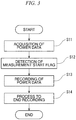
- FIG. 3 is a flowchart illustrating an example of a process for generating a reference value for content in the display device 100.
- the process shown in FIG. 3 is started by, for example, the user performing a predetermined operation on a remote controller (not shown) to instruct the display device 100 to generate a reference value and to play back content that is the object of the generation.
- the content to be monitored includes, as a measurement start flag, video (black screen) during which, for example, power is minimized for several seconds at a start 31 as shown in FIG. 6 .
- the CPU 8-2 of the detection device 104 starts the acquisition of power data at a predetermined sampling period (Step S11).
- the CPU 8-2 stands by until a measurement start flag is detected on the basis of the acquired power data (that is, until a condition (predetermined condition) that the measurement start flag has been detected is satisfied) (Step S12).
- the CPU 8-2 acquires power data at the predetermined sampling period and starts a process of recording the acquired power data in the storage unit 11 (Step S13).
- the CPU 8-2 records the acquired power data in the storage unit 11 together with information indicating the elapsed time after detection of the measurement start flag.
- Step S13 the CPU 8-2 records the time when the measurement start flag was detected in the storage unit 11, and records the acquired power data in the storage unit 11 together with information indicating the time of acquisition.
- This Step 13 is an example of a recording step according to the present invention.
- the CPU 8-2 ends the recording of the power data (Step S14).
- the CPU 8-2 stores the recorded power data as a reference value or the integrated value of the recorded power data as a reference value, for example, in the storage unit 11 in association with the content identification information instructed by the user (Step S14).
- FIG. 4 is a flowchart illustrating an example of the monitoring process performed by the display device 100.
- the monitoring device 500 transmits a signal instructing the display device 100 (detection device 104) to perform display monitoring of content to be distributed with the content identification information being attached thereto, the process being started when the detection device 104 (notification processing unit 7) has received the signal.
- the content to be monitored includes, as a measurement start flag, for example a video (black screen) during which, for example, power is minimized for several seconds at the start 31 as shown in FIG. 6 .
- the reference value of the content is a time-series value of power data as illustrated in FIG. 7 and is stored in the storage unit 11.
- the CPU 8-2 of the detection device 104 starts acquiring power data at a predetermined sampling period (Step S21).
- the CPU 8-2 stands by until detecting the measurement start flag based on the acquired power data (Step S22).
- the CPU 8-2 compares the acquired power data with a reference value at a predetermined sampling period (Step S23).
- the CPU 8-2 determines whether or not the display of the content has ended (Step S24). If the content has not ended (No in Step S24), the CPU 8-2 determines whether or not there is a difference between the acquired power data and the reference value (Step S25).
- Step S25 If there is no difference (No in Step S25), the CPU 8-2 compares the reference value with the power data in the next sampling period (Step S23). On the other hand, if there is a difference (Yes in Step S25), or if the display of the content had ended (Yes in Step S24), the CPU 8-2 reports a signal indicating the comparison result (notification signal) to the monitoring device 500 via the notification processing unit 7 (Step S26).
- FIG. 5 is a flowchart illustrating another example of the monitoring process performed by the display device 100.
- the process shown in FIG. 5 is executed at the time when a certain content is scheduled to be displayed on the display device 100 (detection device 104), for example.
- the CPU 8-2 of the detection device 104 starts acquiring power data at a predetermined sampling period (Step S31).
- the CPU 8-2 determines whether or not the power data acquired in a certain period of time changed (Step S32). If there is a change (Yes in Step S32), the CPU 8-2 acquires power data at the next sampling period (Step S31). On the other hand, if there is no change (No in Step S32), the CPU 8-2 reports to the monitoring device 500 a signal indicating that the display on the display device 100 is abnormal (Step S33).
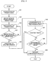
- FIG. 9 is a flowchart illustrating an example of the next process. That is, when the same content is continuously and repeatedly played back on the display device 100, the FIG. 9 shows an example of the process of generating the reference value in the first playback, and monitoring the display state using reference values generated in the second and subsequent playbacks.
- the processing shown in FIG. 9 is started by the user performing a predetermined operation on a remote controller (not shown), instructing the display device 100 to generate a reference value and commence the monitoring after the generation, and instructing the playback of the content to be monitored.
- the content to be monitored includes, as a measurement start flag, a video (black screen) during which, for example, the power is minimized for several seconds at the start 31 as shown in FIG. 6 .
- the CPU 8-2 of the detection device 104 starts acquiring power data at a predetermined sampling period (Step S41).
- the CPU 8-2 stands by until detecting the measurement start flag based on the acquired power data (Step S42).
- the CPU 8-2 Upon detecting the measurement start flag, the CPU 8-2, at a predetermined sampling time, acquires power data and records the acquired power data in the storage unit 11 as a reference value (Step S43).
- the CPU 8-2 determines whether or not the next measurement start flag is detected (Step S44).
- Step S44 When the next measurement start flag is not detected (No in Step S44), the CPU 8-2, at a predetermined sampling time, acquires power data and records the acquired power data in the storage unit 11 as a reference value (Step S43). On the other hand, when the next measurement start flag is detected (Yes in Step S44), the CPU 8-2 ends the recording of the power data (Step S45).
- the CPU 8-2 acquires power data at a predetermined sampling time, and compares the acquired power data with a reference value (Step S46).
- the CPU 8-2 determines whether or not the display of the content has ended (Step S47). If the content has not ended (No in Step S47), the CPU 8-2 determines whether or not there is a difference between the acquired power data and the reference value (Step S48). If there is no difference (No in Step S48), the CPU 8-2 acquires power data at a predetermined sampling time, and compares the acquired power data with the reference value (Step S46).
- Step S48 if there is a difference (Yes in Step S48), or if the display of the content has ended (Yes in Step S47), the CPU 8-2 reports a signal indicating the comparison result (notification signal) to the monitoring device 500 via the notification processing unit 7 (Step S49).
- the result of detecting the power consumed by the display device 100 (predetermined physical quantity), which indicates the operating state of the backlight device 9 (light emitting unit) that changes the luminance of the image displayed on the display device (display device) 100, and the reference value corresponding to power consumption determined in advance for each content displayed by the display device 100 are compared.
- a light emitting unit that changes the luminance of the image displayed by the display device is not limited to a backlight device in a liquid crystal display (or a light emitting element such as an LED included in the backlight device).
- a light emitting element such as an LED included in the backlight device.
- the light emitting element constituting a pixel is an example of the light emitting unit of the present invention.
- a predetermined physical quantity indicating the operation state of the light emitting unit is not limited to the power consumed by the display device 100.
- the predetermined physical quantity indicating the operating state of the light emitting unit may be the luminance of the light emitting unit.
- the power detection circuit 3 may be replaced with a circuit that detects the luminance of the backlight device 9, and the reference value may be replaced with a value corresponding to the luminance.
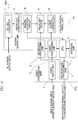
- FIG. 10 the constitution corresponding to the display device 100 shown in FIG. 1 is display device 100a. Also, in FIG. 10 , the same reference numerals are given to the same constitutions or corresponding constitutions as those of the display device 100 of the first exemplary embodiment shown in FIG. 2 .
- the display device 100a shown in FIG. 10 is provided with the liquid crystal panel unit 101, a video processing unit 102a, the power supply unit 103, and the power detection circuit 3.
- the video processing unit 102a is provided with the video input unit 4, the video processing unit 5, the backlight processing unit 6, the notification processing unit 7, the CPU 8, and the storage unit 11.
- the CPU 8 has the functions of the CPU 8-1 and the CPU 8-2 of the first exemplary embodiment. That is, the CPU 8 controls the video processing unit 5 and controls the backlight processing unit 6. Further, the CPU 8 takes in the power data that is the detection result of the power detection circuit 3, stores the generated reference value in the storage unit 11, and transmits the comparison result between the reference value and the power data via the notification processing unit 7.
- the result of detecting the power (predetermined physical quantity) consumed by the display device 100a which indicates the operating state of the backlight device 9 (light emitting unit) that changes the luminance of the image displayed by the display device (display device) 100a, is compared with a reference value corresponding to power consumption determined in advance for each content displayed by the display device 100a.
- a predetermined content it is possible to monitor whether or not a predetermined content has been normally played back on the basis of the comparison result. Therefore, according to the present exemplary embodiment, the display state of content on the display device 100a can be monitored without installing a camera outside the display device 100a.
- FIG. 11 the constitution corresponding to the display device 100 shown in FIG. 1 is a display device 100b.
- the same reference numerals are given to the same constitutions or corresponding constitutions as those of the display device 100a of the second exemplary embodiment shown in FIG. 10 .
- the display device 100b shown in FIG. 11 is provided with a liquid crystal panel unit 101, a video processing unit 102a, and a power supply unit 103b.
- the power supply unit 103b is provided with the AC/DC converter 1, the backlight power supply 2, and a power detection circuit 3b.
- the power detection circuit 3b detects the DC power supplied from the backlight power supply 2 to the backlight device 9 and outputs the detected result to the CPU 8.
- the power consumed by the backlight device 9 that is, part of the electrical power consumed by the display device 100b
- the comparison accuracy can be easily improved.
- the result of detecting the electrical power (predetermined physical quantity) consumed by the display device 100b which indicates the operating state of the backlight device 9 (light emitting unit) that changes the luminance of the image displayed by the display device (display device) 100b, is compared with a reference value corresponding to power consumption determined in advance for each content displayed by the display device 100b.
- a predetermined content has been normally played back on the basis of the comparison result. Therefore, according to the present exemplary embodiment, the display state of content on the display device 100b can be monitored without installing a camera outside the display device 100b.
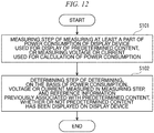
- FIG. 12 is a diagram showing the minimum configuration of the video monitoring method.
- the video monitoring method may include at least steps S101 and S102.
- Step S101 is a measuring step of measuring at least a part of the power consumption of the display device used for displaying predetermined content or measuring the voltage or current used for calculation of the power consumption.
- Step S102 is a determining step of determining, on the basis of the power consumption, voltage or current measured in the measuring step and reference information previously associated with the predetermined content, whether or not the predetermined content has been displayed on the display device.
- Step S101 and Step S102 may be configured as follows. That is, in a display device provided with a liquid crystal panel and a backlight unit and that is used for displaying predetermined content, Step S101 may be a measuring step of measuring the luminance of at least a part of light emitted by the backlight unit and irradiated on the liquid crystal panel. Step S102 may be a determining step of determining, on the basis of the luminance measured by the measuring step and the reference information previously associated with the predetermined content, whether or not the predetermined content has been displayed on the display device.
- the reference information may include time-series information with respect to the elapsed time during which the predetermined content is played back.
- whether or not a predetermined content has been displayed on the display device may be determined on the basis of the result of a comparison between a plurality of reference values according to the elapsed time indicated by the time-series information and a plurality of luminances measured in the measuring step.
- determining step when a value corresponding to the integrated value of the luminance with respect to one playback time of the predetermined content is included in a predetermined range determined by the reference information, a determination may be made that the predetermined content has been displayed on the display device.
- a video monitoring method comprising:
Landscapes
- Engineering & Computer Science (AREA)
- Databases & Information Systems (AREA)
- Multimedia (AREA)
- Signal Processing (AREA)
- Physics & Mathematics (AREA)
- Computer Hardware Design (AREA)
- General Physics & Mathematics (AREA)
- Theoretical Computer Science (AREA)
- Computer Networks & Wireless Communication (AREA)
- Computer Graphics (AREA)
- Control Of Indicators Other Than Cathode Ray Tubes (AREA)
- Controls And Circuits For Display Device (AREA)
Abstract
Description
- The present invention relates to a video monitoring method, a video monitoring device, and a video monitoring system.
-
Patent Document 1 discloses a constitution in which a camera is provided outside a display device, and by using the camera to capture and record advertising content displayed on the display device, confirms that the intended content is displayed as desired. - [Patent Document 1] Japanese Unexamined Patent Application, First Publication No.
2011-95804 - However, in the constitution disclosed in
Patent Document 1, it is necessary to secure a place for installing the camera outside, being separated a certain distance from the display device, and due to the camera being expensive, there is also the problem of the manufacturing cost of the system being increased. - The present invention has been made in view of the above circumstances, and has as its object to provide a video monitoring method, a video monitoring device, and a video monitoring system capable of monitoring the display state of content on a display device without installing a camera outside the display device.
- To solve the above problems, one exemplary aspect of the present invention is a video monitoring method including: a measuring step of measuring at least a part of power consumption of a display device used for displaying predetermined content, or a voltage or a current used for calculating the power consumption; and a determining step of determining whether the predetermined content has been displayed by the display device, based on any of the power consumption, the voltage or the current measured in the measuring step, and reference information previously associated with the predetermined content.
- One exemplary aspect of the present invention is a video monitoring method including: a measuring step of measuring, by a display device that comprises a liquid crystal panel and a backlight unit and that is used for displaying predetermined content, luminance of at least a part of light emitted by the backlight unit and irradiated on the liquid crystal panel; and a determining step of determining whether the predetermined content has been displayed by the display device based on the luminance measured by the measuring step and reference information previously associated with the predetermined content.
- One exemplary aspect of the present invention is a video monitoring device that determines whether predetermined content has been displayed by a display device, based on at least a part of power consumption of the display device used for displaying the predetermined content and reference information previously associated with the predetermined content.
- One exemplary aspect of the present invention is a video monitoring system including: a measuring device that measures at least a part of power consumption of a display device used for displaying predetermined content, or a voltage or a current used for calculating the power consumption; and a monitoring device that receives a signal from the measuring device via a network, wherein the measuring device or the monitoring device determines whether the predetermined content has been displayed by the display device, based on any of the power consumption, the voltage or the current, and reference information previously associated with the predetermined content.
- According to the present invention, it is possible to monitor the display state of content on a display device without installing a camera outside the display device.
-
-
FIG 1 is a block diagram showing a configuration example of the video delivery system according to the exemplary embodiment of the present invention. -
FIG 2 is a block diagram showing a configuration example of the display device according to the first exemplary embodiment of the present invention. -
FIG. 3 is a flowchart showing an operation example of thedisplay device 100 shown inFIG. 2 . -
FIG. 4 is a flowchart showing an operation example of thedisplay device 100 shown inFIG. 2 . -
FIG. 5 is a flowchart showing an operation example of thedisplay device 100 shown inFIG. 2 . -
FIG. 6 is a schematic diagram used for explaining an operation example of thedisplay device 100 shown inFIG. 2 . -
FIG. 7 is a schematic diagram used for explaining an operation example of thedisplay device 100 shown inFIG. 2 . -
FIG. 8 is a schematic diagram used for explaining an operation example of thedisplay device 100 shown inFIG. 2 . -
FIG. 9 is a flowchart showing another operation example of thedisplay device 100 shown inFIG. 2 . -
FIG. 10 is a block diagram showing a configuration example of the display device according to the second exemplary embodiment of the present invention. -
FIG. 11 is a block diagram showing a configuration example of the display device according to the third exemplary embodiment of the present invention. -
FIG. 12 is a flowchart showing a schematic basic configuration of the exemplary embodiments of the present invention. - Hereinbelow, exemplary embodiments of the present invention will be described with reference to the drawings.
FIG. 1 is a block diagram showing a configuration example of a video distribution system according to the first to third exemplary embodiments of the present invention. Avideo distribution system 1000 illustrated inFIG. 1 includes adisplay device 100, aplayback device 200, anetwork 300, avideo distribution server 400, and amonitoring device 500. In thevideo distribution system 1000 illustrated inFIG. 1 , theplayback device 200 receives content data from thevideo distribution server 400 via thenetwork 300. Here, content data is information representing the content of a medium made up of images, sounds, characters, and the like. Further, theplayback device 200 converts the received content data into a video signal and inputs the video signal to thedisplay device 100. Note that thevideo distribution system 1000, thedisplay device 100, and themonitoring device 500 all correspond to the video monitoring device of this exemplary embodiment. - The
display device 100 displays an image based on the video signal input from theplayback device 200. Thedisplay device 100 is a display device used for displaying predetermined content. In addition, thedisplay device 100 transmits a notification signal indicating the result of monitoring the display state of the content on thedisplay device 100 to themonitoring device 500 via thenetwork 300 as described later. Themonitoring device 500 receives the notification signal transmitted by thedisplay device 100 and also receives information on the playback content from thevideo distribution server 400 via thenetwork 300. The information on the playback content expresses a start flag indicating a start time of the content data distributed by thevideo distribution server 400, the display time of the content data, and the like. For example, themonitoring device 500 records or displays the received notification signal and information on the playback content in association with each other. InFIG. 1 , the video signal may include information representing an image and information representing a sound. In that case, thevideo distribution system 1000 may additionally be provided with a device for playing back sound, and thedisplay device 100 may include a device for playing back sound. - Next, a first exemplary embodiment of the
display device 100 shown inFIG. 1 will be described with reference toFIGS. 2 to 9 .FIG. 2 is a block diagram showing a configuration example of thedisplay device 100 shown inFIG. 1 according to the first exemplary embodiment of the present invention. Thedisplay device 100 shown inFIG. 2 is provided with a liquidcrystal panel unit 101, avideo processing unit 102, apower supply unit 103, and adetection device 104. Note that thedisplay device 100 is provided with a function of requesting thevideo distribution server 400 to distribute desired content via theplayback device 200 and thenetwork 300, for example, in accordance with a user instruction. - The liquid
crystal panel unit 101 is provided with abacklight device 9 and aliquid crystal controller 10. Thebacklight device 9 is a backlight using, for example, an LED (light emitting diode) as a light source. Here, thebacklight device 9 is an example of a backlight unit according to the present invention. Thebacklight device 9 controls the luminance of the backlight in accordance with a predetermined control signal input from thebacklight processing unit 6 in thevideo processing unit 102, uniformly over the entire screen or divided into a plurality of areas. Theliquid crystal controller 10 includes a liquid crystal panel, a drive control circuit for the liquid crystal panel, and the like. Theliquid crystal controller 10 controls the aperture ratio of each pixel of the liquid crystal panel according to a predetermined video signal input from thevideo processing unit 5 in thevideo processing unit 102, and passes light emitted from thebacklight device 9 to display an image. At that time, the control of the brightness of the backlight by thebacklight device 9 and the control of the aperture ratio of the liquid crystal panel by theliquid crystal controller 10 are executed in cooperation. The electrical power consumed by the backlight accounts for a large part of the power consumption in thedisplay device 100. The ratio of the maximum power consumed by the backlight to the power consumed by other circuits ranges from, for example, about 10:1 to several tens:1. - The
video processing unit 102 is provided with avideo input unit 4, avideo processing unit 5, abacklight processing unit 6, and a CPU (Central Processing Unit) 8-1. Thevideo input unit 4 inputs the video signal output from theplayback device 200 shown inFIG. 1 , and after converting for example the signal format, outputs the converted signal to thevideo processing unit 5. Thevideo processing unit 5 performs predetermined video processing on the video signal input from thevideo input unit 4, and outputs the processed video signal to theliquid crystal controller 10. Thevideo processing unit 5 analyzes the contrast component of the video signal input from thevideo input unit 4 and outputs the result to thebacklight processing unit 6. - The
backlight processing unit 6 generates a predetermined control signal on the basis of the analysis result of the contrast component of the video signal input from thevideo processing unit 5 and sends the control signal to thebacklight device 9 to change the brightness of the backlight of the liquid crystal panel. Theliquid crystal controller 10 also sends a predetermined control signal to thebacklight device 9 in accordance with the content of the input video signal, and adjusts the backlight according to the video signal. - The CPU 8-1 includes a ROM (Read Only Memory) and a RAM (Random Access Memory), and controls the
video processing unit 5 and thebacklight processing unit 6 by executing a predetermined program. - The
power supply unit 103 includes an AC/DC (alternating current/direct current)converter 1 and abacklight power supply 2, and supplies predetermined direct current power to each part in thedisplay device 100. The AC/DC converter 1 inputs AC commercial power via apower detection circuit 3 included in thedetection device 104. The AC/DC converter 1 converts the input AC commercial power into a DC voltage required for the liquidcrystal panel unit 101, thevideo processing unit 102, thepower supply unit 103 that is a device itself, and thedetection device 104. Thebacklight power supply 2 supplies predetermined direct-current power to thebacklight device 9 using the output of the AC/DC converter 1 as a power source. - The
detection device 104 is provided with thepower detection circuit 3, anotification processing unit 7, a CPU 8-2, and astorage unit 11. Here, thedetection device 104 is an example of a measuring device according to the present invention. Thepower detection circuit 3 detects the power supplied from the AC commercial power supply to thepower supply unit 103, that is, the power consumption of thedisplay device 100, and outputs a signal representing the detection result to the CPU 8-2. Thepower detection circuit 3 may detect the power by combining an ammeter and a voltmeter using a coil, for example, or may detect the current and the voltage and calculate the power from the product of the current and the voltage. When detecting the power consumption, thepower detection circuit 3 may detect both the voltage and the current, or may detect only one of the current and the voltage. In the power detection circuit 3 (or a power detection circuit according to another exemplary embodiment to be described later), for example, when power is detected by a circuit of which the voltage is known, only the current needs to be detected. Further, for example, when power is calculated in a circuit in which a change in voltage and a change in current have a proportional relationship, one of the voltage and current need only be detected. Thestorage unit 11 stores reference information predetermined for each content displayed by thedisplay device 100. The reference information is information representing the characteristic of each content that appears as a change in the operation state on thedisplay device 100 when thedisplay device 100 displays each content. The reference information is a comparison reference for a predetermined physical quantity detected by thedisplay device 100. Further, the reference information may include time-series information with respect to the elapsed time during which the content is played back on thedisplay device 100, or may include information that does not accompany the elapsed time. In the present exemplary embodiment, as the reference information, a reference value corresponding to power consumption determined in advance for each content displayed on thedisplay device 100 is used. This reference value can be made a value indicating a voltage value or a current value in addition to power consumption. - The reference value corresponding to the power consumption predetermined for each content is, for example, a standard value of power consumed by the
display device 100 when a certain content is displayed on thedisplay device 100. For example, as shown inFIG. 6 , the power consumed by thedisplay device 100 changes with time in accordance with the change in the power consumed by thebacklight device 9 or the like according to the change in the luminance of the video.FIG. 6 shows a change over time of power consumed by thedisplay device 100 when a certain content is displayed on thedisplay device 100, with the horizontal axis representing time and the vertical axis representing power. The curve representing the change in power consumption over time as shown inFIG. 6 changes when the displayed content is different. That is, the standard value of the power consumed by thedisplay device 100 differs for each content, and a different reference value can be set for each content. - When the power consumption changes as shown for example in
FIG. 6 , the reference value can be made a value indicating the change over time of the power consumption as shown for example inFIG. 7 . In this case, the reference value includes a plurality of values corresponding to power consumption at different elapsed times from the start of content display. Alternatively, when the power consumption similarly changes as shown inFIG. 6 , the reference value can for example be made a value indicating the change over time of an integrated value of power consumption from a predetermined start time as shown inFIG. 8 . However, the reference value may be one integrated value when the content has been played back, or may be a plurality of values representing changes in the integrated value with time. In this case, the reference value includes, for example, one or a plurality of values corresponding to the result of integration of power consumption according to the elapsed time from the start of content display. - When the reference value is made a value indicating the change over time of power consumption, although the number of data items constituting the reference value increases, it is possible to accurately determine whether the value is normal or abnormal, and possible to perform the determination in a short time in the case of abnormality. On the other hand, if the reference value is a value indicating a change over time of the integrated value of power consumption or an integrated value of total power consumption (the amount of power required to display one content), the number of data items constituting the reference value decreases, and since the number of times of performing a comparison process can be reduced, the processing load can be reduced.
- The CPU 8-2 includes a ROM and a RAM, and by executing a predetermined program, performs recording of the power data detected by the
power detection circuit 3, comparison of the reference value stored in thestorage unit 11 with the power data, and processing such as determination based on the comparison result. Further, the CPU 8-2 may have, for example, a function of accepting an operation performed by a user on an operator such as a predetermined remote controller, a function of generating a reference value according to a user instruction, and the like. When determining whether or not a certain content is normally displayed, the CPU 8-2 compares the detection result of thepower detection circuit 3 with a reference value stored in advance in thestorage unit 11 as follows. That is, when the reference value is one including a plurality of time-series data representing power consumption at a predetermined sampling period as shown inFIG. 7 , the CPU 8-2 compares the reference value and the detection result of thepower detection circuit 3 as follows. That is, the CPU 8-2 compares the reference value and the detection result of thepower detection circuit 3 at the sampling period or at a plurality of the sampling periods. When the reference value corresponds to the integrated value of power consumption as shown inFIG. 8 , the CPU 8-2 compares the reference value with the detection result of thepower detection circuit 3 as follows. That is, the CPU 8-2 integrates the detection result of thepower detection circuit 3 at a predetermined sampling period, and at the sampling period or at a plurality of the sampling periods, or after a predetermined time has elapsed from the start of content display (or at the end of playback) compares the reference value and the integrated value of the detection result of thepower detection circuit 3. - Further, in the comparison process described above, the CPU 8-2 determines that the content is normally displayed when the error between the reference value and the detection result of the
power detection circuit 3 or the error between the reference value and the integrated value of the detection result is within a predetermined range. When the error is not within the predetermined range, the CPU 8-2 determines that the content is not normally displayed. It should be noted that the CPU 8-2 may determine whether or not content is display normally based on a single comparison result or based on a plurality of comparison results (for example, by majority decision). The CPU 8-2 records the determination result in thestorage unit 11 and outputs the determination result to thenotification processing unit 7. At that time, the CPU 8-2 may record or output all the determination results, or may record or output only some determination results (for example, when not normal). In addition, the CPU 8-2 may record or output a normal or abnormal determination result only once for each content, or record or output the number of times that the display was determined to be normal or the number of times the display was determined to be abnormal when the content is played back a plurality of times in a predetermined period. - The
notification processing unit 7 transmits a notification signal indicating the determination result output by the CPU 8-2 to themonitoring device 500 via thenetwork 300 shown inFIG. 1 . Note that thenotification processing unit 7 may have a function of receiving a predetermined control signal from theplayback device 200, thevideo distribution server 400, themonitoring device 500, and the like via thenetwork 300 shown inFIG. 1 . Thenotification processing unit 7 may for example have a function of receiving a reference value for each content from themonitoring device 500, thevideo distribution server 400, and the like via thenetwork 300 and storing the reference value in thestorage unit 11. Further, thenotification processing unit 7 may have a function of receiving, for example, playback content information (start flag, time, etc.) from thevideo distribution server 400 or the like via thenetwork 300, and instructing the CPU 8-2 to execute processing to determine whether the content is normally displayed. - Next, an operation example of the
display device 100 described with reference toFIGS. 1 and2 will be described referring toFIG. 3. FIG. 3 is a flowchart illustrating an example of a process for generating a reference value for content in thedisplay device 100. The process shown inFIG. 3 is started by, for example, the user performing a predetermined operation on a remote controller (not shown) to instruct thedisplay device 100 to generate a reference value and to play back content that is the object of the generation. In this operation example, the content to be monitored includes, as a measurement start flag, video (black screen) during which, for example, power is minimized for several seconds at astart 31 as shown inFIG. 6 . - In the process shown in
FIG. 3 , first, the CPU 8-2 of thedetection device 104 starts the acquisition of power data at a predetermined sampling period (Step S11). Next, the CPU 8-2 stands by until a measurement start flag is detected on the basis of the acquired power data (that is, until a condition (predetermined condition) that the measurement start flag has been detected is satisfied) (Step S12). Upon detecting the measurement start flag, the CPU 8-2 acquires power data at the predetermined sampling period and starts a process of recording the acquired power data in the storage unit 11 (Step S13). In Step S13, the CPU 8-2 records the acquired power data in thestorage unit 11 together with information indicating the elapsed time after detection of the measurement start flag. Alternatively, in Step S13, the CPU 8-2 records the time when the measurement start flag was detected in thestorage unit 11, and records the acquired power data in thestorage unit 11 together with information indicating the time of acquisition. This Step 13 is an example of a recording step according to the present invention. Next, for example, when the user performs a predetermined operation on a remote controller (not shown) instructing the end of the generation of the reference value, the CPU 8-2 ends the recording of the power data (Step S14). Further, the CPU 8-2 stores the recorded power data as a reference value or the integrated value of the recorded power data as a reference value, for example, in thestorage unit 11 in association with the content identification information instructed by the user (Step S14). - Next, with reference to
FIG. 4 , a description will be given for the process of monitoring whether or not content is normally played back on thedisplay device 100.FIG. 4 is a flowchart illustrating an example of the monitoring process performed by thedisplay device 100. In the process illustrated inFIG. 4 , themonitoring device 500 transmits a signal instructing the display device 100 (detection device 104) to perform display monitoring of content to be distributed with the content identification information being attached thereto, the process being started when the detection device 104 (notification processing unit 7) has received the signal. In this operation example, the content to be monitored includes, as a measurement start flag, for example a video (black screen) during which, for example, power is minimized for several seconds at thestart 31 as shown inFIG. 6 . In this operation example, it is assumed that the reference value of the content is a time-series value of power data as illustrated inFIG. 7 and is stored in thestorage unit 11. - In the process shown in
FIG. 4 , first, the CPU 8-2 of thedetection device 104 starts acquiring power data at a predetermined sampling period (Step S21). Next, the CPU 8-2 stands by until detecting the measurement start flag based on the acquired power data (Step S22). Upon detecting the measurement start flag, the CPU 8-2 compares the acquired power data with a reference value at a predetermined sampling period (Step S23). Next, the CPU 8-2 determines whether or not the display of the content has ended (Step S24). If the content has not ended (No in Step S24), the CPU 8-2 determines whether or not there is a difference between the acquired power data and the reference value (Step S25). If there is no difference (No in Step S25), the CPU 8-2 compares the reference value with the power data in the next sampling period (Step S23). On the other hand, if there is a difference (Yes in Step S25), or if the display of the content had ended (Yes in Step S24), the CPU 8-2 reports a signal indicating the comparison result (notification signal) to themonitoring device 500 via the notification processing unit 7 (Step S26). - Next, with reference to
FIG. 5 , another process for monitoring whether or not the content is normally played back on thedisplay device 100 will be described.FIG. 5 is a flowchart illustrating another example of the monitoring process performed by thedisplay device 100. The process shown inFIG. 5 is executed at the time when a certain content is scheduled to be displayed on the display device 100 (detection device 104), for example. - In the process shown in
FIG. 5 , first, the CPU 8-2 of thedetection device 104 starts acquiring power data at a predetermined sampling period (Step S31). Next, the CPU 8-2 determines whether or not the power data acquired in a certain period of time changed (Step S32). If there is a change (Yes in Step S32), the CPU 8-2 acquires power data at the next sampling period (Step S31). On the other hand, if there is no change (No in Step S32), the CPU 8-2 reports to the monitoring device 500 a signal indicating that the display on thedisplay device 100 is abnormal (Step S33). - Next, another operation example of the
display device 100 described with reference toFIGS. 1 and2 will be described with reference toFIG. 9. FIG. 9 is a flowchart illustrating an example of the next process. That is, when the same content is continuously and repeatedly played back on thedisplay device 100, theFIG. 9 shows an example of the process of generating the reference value in the first playback, and monitoring the display state using reference values generated in the second and subsequent playbacks. The processing shown inFIG. 9 is started by the user performing a predetermined operation on a remote controller (not shown), instructing thedisplay device 100 to generate a reference value and commence the monitoring after the generation, and instructing the playback of the content to be monitored. In this operation example, the content to be monitored includes, as a measurement start flag, a video (black screen) during which, for example, the power is minimized for several seconds at thestart 31 as shown inFIG. 6 . - In the process shown in
FIG. 9 , first, the CPU 8-2 of thedetection device 104 starts acquiring power data at a predetermined sampling period (Step S41). Next, the CPU 8-2 stands by until detecting the measurement start flag based on the acquired power data (Step S42). Upon detecting the measurement start flag, the CPU 8-2, at a predetermined sampling time, acquires power data and records the acquired power data in thestorage unit 11 as a reference value (Step S43). Next, the CPU 8-2 determines whether or not the next measurement start flag is detected (Step S44). When the next measurement start flag is not detected (No in Step S44), the CPU 8-2, at a predetermined sampling time, acquires power data and records the acquired power data in thestorage unit 11 as a reference value (Step S43). On the other hand, when the next measurement start flag is detected (Yes in Step S44), the CPU 8-2 ends the recording of the power data (Step S45). - Next, the CPU 8-2 acquires power data at a predetermined sampling time, and compares the acquired power data with a reference value (Step S46). Next, the CPU 8-2 determines whether or not the display of the content has ended (Step S47). If the content has not ended (No in Step S47), the CPU 8-2 determines whether or not there is a difference between the acquired power data and the reference value (Step S48). If there is no difference (No in Step S48), the CPU 8-2 acquires power data at a predetermined sampling time, and compares the acquired power data with the reference value (Step S46). On the other hand, if there is a difference (Yes in Step S48), or if the display of the content has ended (Yes in Step S47), the CPU 8-2 reports a signal indicating the comparison result (notification signal) to the
monitoring device 500 via the notification processing unit 7 (Step S49). - As described above, in the present exemplary embodiment, the result of detecting the power consumed by the display device 100 (predetermined physical quantity), which indicates the operating state of the backlight device 9 (light emitting unit) that changes the luminance of the image displayed on the display device (display device) 100, and the reference value corresponding to power consumption determined in advance for each content displayed by the
display device 100 are compared. In the present exemplary embodiment, it is possible to monitor whether or not a predetermined content has been normally played back based on the comparison result. Therefore, according to the present exemplary embodiment, it is possible to monitor the display state of content on thedisplay device 100 without providing a camera outside thedisplay device 100. - In the present invention, a light emitting unit that changes the luminance of the image displayed by the display device is not limited to a backlight device in a liquid crystal display (or a light emitting element such as an LED included in the backlight device). For example, in a display device using a self-luminous element such as an organic EL (organic electroluminescence) light emitting diode, the light emitting element constituting a pixel is an example of the light emitting unit of the present invention.
- Further, a predetermined physical quantity indicating the operation state of the light emitting unit is not limited to the power consumed by the
display device 100. The predetermined physical quantity indicating the operating state of the light emitting unit may be the luminance of the light emitting unit. In the case where the predetermined physical quantity is the luminance of the light emitting unit, for example, in the configuration shown inFIG. 2 , thepower detection circuit 3 may be replaced with a circuit that detects the luminance of thebacklight device 9, and the reference value may be replaced with a value corresponding to the luminance. - In addition, this exemplary embodiment can for example be modified as follows.
- (1) For example, the
display device 100 shown inFIG. 1 may be provided with a plurality of display devices to constitute a multi-display that divides and displays one screen. In this case, a reference value may be set for each display device, and the display state of content may be monitored on all the display devices. Alternatively, a reference value may be set for one or a plurality of partial display devices, and the display state of the content may be monitored by the partial display devices. - (2) The content measurement start flag is not limited to a video (black screen) set at the
start 31 during which the power is minimized. For example, a predetermined instruction transmitted from themonitoring device 500 or thevideo distribution server 400 to thedisplay device 100 may be used as the measurement start flag. Alternatively, information indicating the start time of the target content may be transmitted from themonitoring device 500 or thevideo distribution server 400 to thedisplay device 100 in advance, and the start time may be used as a measurement start flag. Alternatively, not only a black screen but an image of a fixed time having a pattern with a predetermined luminance change may be used as a measurement start flag. Further, a measurement start flag may be provided for each content, or provided for a plurality of contents gathered into one group. In this case, the reference value can for example be set so as to cover a plurality of contents. - (3) The method of generating the reference value is not limited to a method of generating the reference value by actually playing back the content on the
display device 100. For example, the reference value can be generated by playing back the content using another display device of the same model as thedisplay device 100. Alternatively, the reference value can be generated by playing back the content using another display device of the same type having the same power consumption change tendency as thedisplay device 100. In this case, for example, the reference value can be calibrated in advance using a predetermined image, or can be calibrated using the value of an image at a predetermined playback time during display of the content. - (4) In the present exemplary embodiment, the comparison between the reference value and the measured power data or the integrated value of the power data is performed by the
detection device 104, but the comparison between the detection result and the reference value may also be performed by another device (for example, themonitoring device 500 or the like). For example, thedetection device 104 may notify another device of information indicating the detection result (information indicating the time-series detection value, the integrated value of the detection value, and the like), and the display state may be monitored by a comparison between the reference value and the detection result being performed by the other device. - Next, a second exemplary embodiment of the
display device 100 shown inFIG. 1 will be described with reference toFIG. 10 . However, inFIG. 10 , the constitution corresponding to thedisplay device 100 shown inFIG. 1 isdisplay device 100a. Also, inFIG. 10 , the same reference numerals are given to the same constitutions or corresponding constitutions as those of thedisplay device 100 of the first exemplary embodiment shown inFIG. 2 . Thedisplay device 100a shown inFIG. 10 is provided with the liquidcrystal panel unit 101, avideo processing unit 102a, thepower supply unit 103, and thepower detection circuit 3. - The
video processing unit 102a is provided with thevideo input unit 4, thevideo processing unit 5, thebacklight processing unit 6, thenotification processing unit 7, theCPU 8, and thestorage unit 11. TheCPU 8 has the functions of the CPU 8-1 and the CPU 8-2 of the first exemplary embodiment. That is, theCPU 8 controls thevideo processing unit 5 and controls thebacklight processing unit 6. Further, theCPU 8 takes in the power data that is the detection result of thepower detection circuit 3, stores the generated reference value in thestorage unit 11, and transmits the comparison result between the reference value and the power data via thenotification processing unit 7. - Also in the second exemplary embodiment, as in the first exemplary embodiment, the result of detecting the power (predetermined physical quantity) consumed by the
display device 100a, which indicates the operating state of the backlight device 9 (light emitting unit) that changes the luminance of the image displayed by the display device (display device) 100a, is compared with a reference value corresponding to power consumption determined in advance for each content displayed by thedisplay device 100a. In the present exemplary embodiment, it is possible to monitor whether or not a predetermined content has been normally played back on the basis of the comparison result. Therefore, according to the present exemplary embodiment, the display state of content on thedisplay device 100a can be monitored without installing a camera outside thedisplay device 100a. - Next, a third exemplary embodiment of the
display device 100 shown inFIG. 1 will be described with reference toFIG. 11 . Note that inFIG. 11 , the constitution corresponding to thedisplay device 100 shown inFIG. 1 is adisplay device 100b. InFIG. 11 , the same reference numerals are given to the same constitutions or corresponding constitutions as those of thedisplay device 100a of the second exemplary embodiment shown inFIG. 10 . Thedisplay device 100b shown inFIG. 11 is provided with a liquidcrystal panel unit 101, avideo processing unit 102a, and a power supply unit 103b. - The power supply unit 103b is provided with the AC/
DC converter 1, thebacklight power supply 2, and apower detection circuit 3b. Thepower detection circuit 3b detects the DC power supplied from thebacklight power supply 2 to thebacklight device 9 and outputs the detected result to theCPU 8. In the third exemplary embodiment, since the power consumed by the backlight device 9 (that is, part of the electrical power consumed by thedisplay device 100b) is measured by thepower detection circuit 3b, compared with other exemplary embodiments the comparison accuracy can be easily improved. - Also in the third exemplary embodiment, similarly to the first exemplary embodiment and the second exemplary embodiment, the result of detecting the electrical power (predetermined physical quantity) consumed by the
display device 100b, which indicates the operating state of the backlight device 9 (light emitting unit) that changes the luminance of the image displayed by the display device (display device) 100b, is compared with a reference value corresponding to power consumption determined in advance for each content displayed by thedisplay device 100b. In the present exemplary embodiment, it is possible to monitor whether or not a predetermined content has been normally played back on the basis of the comparison result. Therefore, according to the present exemplary embodiment, the display state of content on thedisplay device 100b can be monitored without installing a camera outside thedisplay device 100b. -
FIG. 12 is a diagram showing the minimum configuration of the video monitoring method. As shown in the figure, the video monitoring method may include at least steps S101 and S102. Here, Step S101 is a measuring step of measuring at least a part of the power consumption of the display device used for displaying predetermined content or measuring the voltage or current used for calculation of the power consumption. Step S102 is a determining step of determining, on the basis of the power consumption, voltage or current measured in the measuring step and reference information previously associated with the predetermined content, whether or not the predetermined content has been displayed on the display device. - In
FIG. 12 , Step S101 and Step S102 may be configured as follows. That is, in a display device provided with a liquid crystal panel and a backlight unit and that is used for displaying predetermined content, Step S101 may be a measuring step of measuring the luminance of at least a part of light emitted by the backlight unit and irradiated on the liquid crystal panel. Step S102 may be a determining step of determining, on the basis of the luminance measured by the measuring step and the reference information previously associated with the predetermined content, whether or not the predetermined content has been displayed on the display device. - There may be another step of generating reference information on the basis of the luminance that is measured in a display device or another display device that displays a predetermined content. The reference information may include time-series information with respect to the elapsed time during which the predetermined content is played back. In the determining step, whether or not a predetermined content has been displayed on the display device may be determined on the basis of the result of a comparison between a plurality of reference values according to the elapsed time indicated by the time-series information and a plurality of luminances measured in the measuring step. Further, in the determining step, when a value corresponding to the integrated value of the luminance with respect to one playback time of the predetermined content is included in a predetermined range determined by the reference information, a determination may be made that the predetermined content has been displayed on the display device.
- According to the exemplary embodiments and the minimum configuration example of the present invention as described above, it is possible to monitor the display state of content on a display device without providing a camera outside the display device.
- Exemplary embodiments of the present invention have been described in detail with reference to the drawings. However, the specific configurations are not limited to these exemplary embodiments, with designs and the like within a scope not departing from the gist of the present invention also included. In addition, a part or all of a program executed by a computer with one or a plurality of CPUs included in the above exemplary embodiments can be distributed via a communication line or a computer-readable recording medium.
-
- 1000: Video distribution system
- 100, 100a, 100b: Display device
- 200: Playback device
- 300: Network
- 400: Video distribution server
- 500: Monitoring device
- 101: Liquid crystal panel unit
- 102, 102a: Video processing unit
- 103, 103b: Power supply unit
- 104: Detection device
- 1: AC/DC converter
- 2: Backlight power supply
- 3, 3b: Power detection circuit
- 4: Video input unit
- 5: Video processing unit
- 6: Backlight processing unit
- 7: Notification processing unit
- 8, 8-1, 8-2: CPU
- 9: Backlight device
- 10: Liquid crystal controller
- 11: Storage unit
- Further embodiments are disclosed in the following examples.
- A video monitoring method comprising:
- a measuring step of measuring at least a part of power consumption of a display device used for displaying predetermined content, or a voltage or a current used for calculating the power consumption; and
- a determining step of determining whether the predetermined content has been displayed by the display device, based on any of the power consumption, the voltage or the current measured in the measuring step, and reference information previously associated with the predetermined content.
- 2. The video monitoring method according to example 1, further comprising:
a step of generating the reference information based on at least the part of power consumption of the display device or another display device that displayed the predetermined content, or a voltage or a current used for calculating the power consumption. - 3. The video monitoring method according to example 1 or example 2, wherein the reference information comprises time-series information with respect to an elapsed time during which the predetermined content is played back.
- 4. The video monitoring method according to example 3, wherein the determining step determines whether the predetermined content has been displayed by the display device based on a result of a comparison between a plurality of reference values according to the elapsed time indicated by the time-series information and a plurality of power consumption values measured by the measuring step.
- 5. The video monitoring method according to example 1 or example 2, wherein the determining step determines that the predetermined content has been displayed by the display device in a case where an integrated value of the power consumption or of the current with respect to one playback time of the predetermined content is included in a predetermined range determined by the reference information.
- 6. The video monitoring method according to any one of examples 1 to 5, further comprising:
a recording step of, when a predetermined condition has been satisfied, recording: any of the power consumption, the voltage or the current measured by the measuring step; and an elapsed time since the predetermined condition was satisfied or a time of day. - 7. The video monitoring method according to example 6, wherein the predetermined condition is a condition of the power consumption measured by the measuring step.
- 8. The video monitoring method according to any one of examples 1 to 7,
wherein the display device comprises a light emitting unit that emits light used for display; and
the part of power consumption is power consumption of the light emitting unit. - 9. The video monitoring method according to any one of examples 1 to 8, wherein the measuring step is performed by a measuring device connected to a network.
- 10. The video monitoring method according to any one of examples 1 to 9, wherein the measuring step is repeated in a predetermined period.
- 11. A video monitoring method comprising:
- a measuring step of measuring, by a display device that comprises a liquid crystal panel and a backlight unit and that is used for displaying predetermined content, luminance of at least a part of light emitted by the backlight unit and irradiated on the liquid crystal panel; and
- a determining step of determining whether the predetermined content has been displayed by the display device based on the luminance measured by the measuring step and reference information previously associated with the predetermined content.
- 12. The video monitoring method according to example 11, further comprising:
a step of generating the reference information based on luminance measured in the display device or another display device that displayed the predetermined content. - 13. The video monitoring method according to example 11 or 12, wherein the reference information comprises time-series information with respect to an elapsed time during which the predetermined content is played back.
- 14. The video monitoring method according to example 13, wherein the determining step determines whether the predetermined content has been displayed by the display device based on a result of a comparison between a plurality of reference values according to the elapsed time indicated by the time-series information and a plurality of power consumption values measured by the measuring step.
- 15. The video monitoring method according to example 11 or 12, wherein the determining step determines that the predetermined content has been displayed by the display device in a case where a value corresponding to an integrated value of the luminance with respect to one playback time of the predetermined content is included in a predetermined range determined by the reference information.
- 16. A video monitoring device that determines whether predetermined content has been displayed by a display device, based on at least a part of power consumption of the display device used for displaying the predetermined content and reference information previously associated with the predetermined content.
- 17. A video monitoring system comprising:
- a measuring device that measures at least a part of power consumption of a display device used for displaying predetermined content, or a voltage or a current used for calculating the power consumption; and
- a monitoring device that receives a signal from the measuring device via a network,
- wherein the measuring device or the monitoring device determines whether the predetermined content has been displayed by the display device, based on any of the power consumption, the voltage or the current, and reference information previously associated with the predetermined content.
Claims (10)
- A video monitoring method comprising:a measuring step of measuring at least a part of power consumption of a display device used for displaying predetermined content, or a voltage or a current used for calculating the power consumption; anda determining step of determining whether the predetermined content has been displayed by the display device, based on any of the power consumption, the voltage or the current measured in the measuring step, and reference information previously associated with the predetermined content, whereinthe determining step determines that the predetermined content has been displayed by the display device in a case where an integrated value of the power consumption or of the current with respect to one playback time of the predetermined content is included in a predetermined range determined by the reference information.
- The video monitoring method according to claim 1, further comprising:a recording step of recording the measured at least a part of power consumption of the display device used for displaying predetermined content that is repeatedly played back, or the measured voltage or the measured current used for calculating the power consumption as a reference value; whereinaid reference information being the reference value recorded in said recording step.
- The video monitoring method according to claim 1 or 2, further comprising:
a step of generating the reference information based on at least the part of power consumption of the display device or another display device that displayed the predetermined content, or a voltage or a current used for calculating the power consumption. - The video monitoring method according to any one of claims 1 to 3, further comprising:
a recording step of, when a predetermined condition has been satisfied, recording: any of the power consumption, the voltage or the current measured by the measuring step; and an elapsed time since the predetermined condition was satisfied or a time of day. - The video monitoring method according to claim 4, wherein the predetermined condition is a condition of the power consumption measured by the measuring step.
- The video monitoring method according to any one of claims 1 to 5,
wherein the display device comprises a light emitting unit that emits light used for display; and
the part of power consumption is power consumption of the light emitting unit. - The video monitoring method according to any one of claims 1 to 6, wherein the measuring step is performed by a measuring device connected to a network.
- The video monitoring method according to any one of claims 1 to 7, wherein the measuring step is repeated in a predetermined period.
- A video monitoring device comprising means adapted to determine whether predetermined content has been displayed by a display device, based on at least a part of power consumption of the display device used for displaying the predetermined content and reference information previously associated with the predetermined content, wherein
said video monitoring device being adapted to determine that the predetermined content has been displayed by the display device in a case where an integrated value of the power consumption or of a current with respect to one playback time of the predetermined content is included in a predetermined range determined by the reference information. - A video monitoring system comprising:the video monitoring device according to claim 9,a measuring device adapted to measure at least the part of power consumption or a voltage or the current used for calculating the power consumption; andwherein the monitoring device receives a signal from the measuring device via a network., andthe video monitoring device determines whether the predetermined content has been displayed by the display device, based on any of the power consumption, the voltage or the current, and the reference information.
Priority Applications (1)
| Application Number | Priority Date | Filing Date | Title |
|---|---|---|---|
| EP20195477.3A EP3800895B1 (en) | 2017-06-16 | 2017-06-16 | Video monitoring method, video monitoring device, and video monitoring system |
Applications Claiming Priority (3)
| Application Number | Priority Date | Filing Date | Title |
|---|---|---|---|
| PCT/JP2017/022352 WO2018229974A1 (en) | 2017-06-16 | 2017-06-16 | Video monitoring method, video monitoring device, and video monitoring system |
| EP17914005.8A EP3595300B1 (en) | 2017-06-16 | 2017-06-16 | Video monitoring method, video monitoring device, and video monitoring system |
| EP20195477.3A EP3800895B1 (en) | 2017-06-16 | 2017-06-16 | Video monitoring method, video monitoring device, and video monitoring system |
Related Parent Applications (2)
| Application Number | Title | Priority Date | Filing Date |
|---|---|---|---|
| EP17914005.8A Division-Into EP3595300B1 (en) | 2017-06-16 | 2017-06-16 | Video monitoring method, video monitoring device, and video monitoring system |
| EP17914005.8A Division EP3595300B1 (en) | 2017-06-16 | 2017-06-16 | Video monitoring method, video monitoring device, and video monitoring system |
Publications (2)
| Publication Number | Publication Date |
|---|---|
| EP3800895A1 true EP3800895A1 (en) | 2021-04-07 |
| EP3800895B1 EP3800895B1 (en) | 2024-01-10 |
Family
ID=64660584
Family Applications (2)
| Application Number | Title | Priority Date | Filing Date |
|---|---|---|---|
| EP17914005.8A Active EP3595300B1 (en) | 2017-06-16 | 2017-06-16 | Video monitoring method, video monitoring device, and video monitoring system |
| EP20195477.3A Active EP3800895B1 (en) | 2017-06-16 | 2017-06-16 | Video monitoring method, video monitoring device, and video monitoring system |
Family Applications Before (1)
| Application Number | Title | Priority Date | Filing Date |
|---|---|---|---|
| EP17914005.8A Active EP3595300B1 (en) | 2017-06-16 | 2017-06-16 | Video monitoring method, video monitoring device, and video monitoring system |
Country Status (4)
| Country | Link |
|---|---|
| US (2) | US20210125569A1 (en) |
| EP (2) | EP3595300B1 (en) |
| CN (1) | CN110463200B (en) |
| WO (1) | WO2018229974A1 (en) |
Families Citing this family (2)
| Publication number | Priority date | Publication date | Assignee | Title |
|---|---|---|---|---|
| WO2021015751A1 (en) * | 2019-07-24 | 2021-01-28 | Hewlett-Packard Development Company, L.P. | Touchscreen calibration circuit |
| US11647178B2 (en) * | 2020-02-07 | 2023-05-09 | Sony Corporation | Digital television rendering verification |
Citations (4)
| Publication number | Priority date | Publication date | Assignee | Title |
|---|---|---|---|---|
| US3806805A (en) * | 1971-01-25 | 1974-04-23 | Plessey Handel Investment Ag | Systems for monitoring mains electrical power supplies |
| EP2023328A2 (en) * | 2007-08-03 | 2009-02-11 | Coretronic Corporation | Display with a luminance and color temperature control system and method for controlling the luminance of a display |
| EP2214334A1 (en) * | 2007-02-23 | 2010-08-04 | Mediciones Eléctricas de Andalucía, S.L. | Device for measuring consumption patterns through the electric mains and method for use |
| JP2011095804A (en) | 2009-10-27 | 2011-05-12 | Canon It Solutions Inc | Apparatus and system for confirming effect of outdoor advertisement, control method of the same, program, and storage medium storing the program |
Family Cites Families (10)
| Publication number | Priority date | Publication date | Assignee | Title |
|---|---|---|---|---|
| JP2001067119A (en) * | 1999-08-25 | 2001-03-16 | Mk Seiko Co Ltd | Display device |
| JP3089634U (en) * | 2002-04-30 | 2002-10-31 | 船井電機株式会社 | Television adjustment system, television and television adjustment device |
| US20090054100A1 (en) * | 2005-06-02 | 2009-02-26 | Hideo Ishida | Television broadcast reception device, television broadcast reception device control method, and television broadcast reception device power consumption management method |
| JP2009017443A (en) * | 2007-07-09 | 2009-01-22 | Fujitsu Ltd | Video content viewing judgment system |
| RU2010118559A (en) * | 2007-10-17 | 2011-11-27 | Медисионес Електрикас Де Андалусиа, С.Л. (Es) | METHOD FOR DETERMINING CONSUMPTION BY MEANS OF ELECTRIC TRANSMISSION LINES AND DEVICE FOR ITS IMPLEMENTATION |
| JP5645647B2 (en) * | 2010-03-01 | 2014-12-24 | キヤノン株式会社 | Power control system and control method thereof |
| JP2012235420A (en) * | 2011-05-09 | 2012-11-29 | Video Research:Kk | Terminal device and control method |
| JP2013115521A (en) * | 2011-11-25 | 2013-06-10 | Sharp Corp | Display device and program thereof |
| CN103513477B (en) * | 2012-06-26 | 2018-03-09 | 富泰华工业(深圳)有限公司 | Liquid crystal display and its detection method |
| WO2016200576A1 (en) * | 2015-06-09 | 2016-12-15 | Technicolor Usa, Inc. | Method, appartus and system for the rendering of content |
-
2017
- 2017-06-16 EP EP17914005.8A patent/EP3595300B1/en active Active
- 2017-06-16 US US16/497,739 patent/US20210125569A1/en not_active Abandoned
- 2017-06-16 CN CN201780088984.5A patent/CN110463200B/en active Active
- 2017-06-16 WO PCT/JP2017/022352 patent/WO2018229974A1/en not_active Ceased
- 2017-06-16 EP EP20195477.3A patent/EP3800895B1/en active Active
-
2021
- 2021-10-08 US US17/497,278 patent/US20220028346A1/en not_active Abandoned
Patent Citations (4)
| Publication number | Priority date | Publication date | Assignee | Title |
|---|---|---|---|---|
| US3806805A (en) * | 1971-01-25 | 1974-04-23 | Plessey Handel Investment Ag | Systems for monitoring mains electrical power supplies |
| EP2214334A1 (en) * | 2007-02-23 | 2010-08-04 | Mediciones Eléctricas de Andalucía, S.L. | Device for measuring consumption patterns through the electric mains and method for use |
| EP2023328A2 (en) * | 2007-08-03 | 2009-02-11 | Coretronic Corporation | Display with a luminance and color temperature control system and method for controlling the luminance of a display |
| JP2011095804A (en) | 2009-10-27 | 2011-05-12 | Canon It Solutions Inc | Apparatus and system for confirming effect of outdoor advertisement, control method of the same, program, and storage medium storing the program |
Also Published As
| Publication number | Publication date |
|---|---|
| CN110463200A (en) | 2019-11-15 |
| EP3595300A1 (en) | 2020-01-15 |
| EP3595300A4 (en) | 2020-01-15 |
| WO2018229974A1 (en) | 2018-12-20 |
| CN110463200B (en) | 2021-09-07 |
| EP3595300B1 (en) | 2021-08-18 |
| EP3800895B1 (en) | 2024-01-10 |
| US20210125569A1 (en) | 2021-04-29 |
| US20220028346A1 (en) | 2022-01-27 |
Similar Documents
| Publication | Publication Date | Title |
|---|---|---|
| AU2014371874B2 (en) | Life prediction method, life prediction program, and life prediction device | |
| US7791717B2 (en) | Reflective display device testing system, apparatus, and method | |
| JP5334602B2 (en) | Color calibration system | |
| JP5014154B2 (en) | Image display method and image display apparatus | |
| US8890906B2 (en) | Method and system for remotely calibrating display of image data | |
| US20220028346A1 (en) | Video monitoring method, video monitoring device, and video monitoring system | |
| US11790579B2 (en) | Production efficiency improvement assisting system | |
| EP3361471A1 (en) | Light-emitting diode display device | |
| CN106782235B (en) | Display screen abnormity detection method and device and display screen equipment | |
| EP3010009A1 (en) | Multi-monitor system, and computer program and display device used in multi-monitor system | |
| US20220406270A1 (en) | Flicker measurement device and measurement method | |
| US10268439B2 (en) | Prediction system, prediction method, and computer program | |
| US20160307541A1 (en) | Image display apparatus and method for controlling the same | |
| JP6597606B2 (en) | Monitoring system, monitoring device, server, operation method of monitoring device, operation method of server, and program | |
| US20140375563A1 (en) | Calibration system and calibration method for display device | |
| JPWO2010116467A1 (en) | Image display device and image processing method | |
| US8230287B2 (en) | Image data test unit, image apparatus having the same, and method of testing image data using the same | |
| JP6041784B2 (en) | Power measuring apparatus, power measuring method, and program | |
| JP2015118622A (en) | System for predicting stable state of image output device, method for controlling system, and program | |
| JP5485042B2 (en) | Progress prediction device, progress prediction method, and program | |
| CN108028918B (en) | Image signal generating device and display measuring device | |
| JP2009291888A (en) | Screw counter device | |
| CN121459737A (en) | Method for improving lifetime of a display, related display, computer program and apparatus | |
| JP2016085349A (en) | Display device, management device, and computer program | |
| JP2020087679A (en) | Display device, inspection method |
Legal Events
| Date | Code | Title | Description |
|---|---|---|---|
| PUAI | Public reference made under article 153(3) epc to a published international application that has entered the european phase |
Free format text: ORIGINAL CODE: 0009012 |
|
| STAA | Information on the status of an ep patent application or granted ep patent |
Free format text: STATUS: REQUEST FOR EXAMINATION WAS MADE |
|
| 17P | Request for examination filed |
Effective date: 20200917 |
|
| AC | Divisional application: reference to earlier application |
Ref document number: 3595300 Country of ref document: EP Kind code of ref document: P |
|
| AK | Designated contracting states |
Kind code of ref document: A1 Designated state(s): AL AT BE BG CH CY CZ DE DK EE ES FI FR GB GR HR HU IE IS IT LI LT LU LV MC MK MT NL NO PL PT RO RS SE SI SK SM TR |
|
| RBV | Designated contracting states (corrected) |
Designated state(s): AL AT BE BG CH CY CZ DE DK EE ES FI FR GB GR HR HU IE IS IT LI LT LU LV MC MK MT NL NO PL PT RO RS SE SI SK SM TR |
|
| STAA | Information on the status of an ep patent application or granted ep patent |
Free format text: STATUS: EXAMINATION IS IN PROGRESS |
|
| 17Q | First examination report despatched |
Effective date: 20230112 |
|
| RAP3 | Party data changed (applicant data changed or rights of an application transferred) |
Owner name: SHARP NEC DISPLAY SOLUTIONS, LTD. |
|
| GRAP | Despatch of communication of intention to grant a patent |
Free format text: ORIGINAL CODE: EPIDOSNIGR1 |
|
| STAA | Information on the status of an ep patent application or granted ep patent |
Free format text: STATUS: GRANT OF PATENT IS INTENDED |
|
| INTG | Intention to grant announced |
Effective date: 20230918 |
|
| GRAS | Grant fee paid |
Free format text: ORIGINAL CODE: EPIDOSNIGR3 |
|
| GRAA | (expected) grant |
Free format text: ORIGINAL CODE: 0009210 |
|
| STAA | Information on the status of an ep patent application or granted ep patent |
Free format text: STATUS: THE PATENT HAS BEEN GRANTED |
|
| AC | Divisional application: reference to earlier application |
Ref document number: 3595300 Country of ref document: EP Kind code of ref document: P |
|
| AK | Designated contracting states |
Kind code of ref document: B1 Designated state(s): AL AT BE BG CH CY CZ DE DK EE ES FI FR GB GR HR HU IE IS IT LI LT LU LV MC MK MT NL NO PL PT RO RS SE SI SK SM TR |
|
| REG | Reference to a national code |
Ref country code: GB Ref legal event code: FG4D |
|
| REG | Reference to a national code |
Ref country code: CH Ref legal event code: EP |
|
| REG | Reference to a national code |
Ref country code: DE Ref legal event code: R096 Ref document number: 602017078464 Country of ref document: DE |
|
| REG | Reference to a national code |
Ref country code: IE Ref legal event code: FG4D |
|
| REG | Reference to a national code |
Ref country code: LT Ref legal event code: MG9D |
|
| REG | Reference to a national code |
Ref country code: NL Ref legal event code: MP Effective date: 20240110 |
|
| REG | Reference to a national code |
Ref country code: AT Ref legal event code: MK05 Ref document number: 1649789 Country of ref document: AT Kind code of ref document: T Effective date: 20240110 |
|
| PG25 | Lapsed in a contracting state [announced via postgrant information from national office to epo] |
Ref country code: NL Free format text: LAPSE BECAUSE OF FAILURE TO SUBMIT A TRANSLATION OF THE DESCRIPTION OR TO PAY THE FEE WITHIN THE PRESCRIBED TIME-LIMIT Effective date: 20240110 |
|
| PG25 | Lapsed in a contracting state [announced via postgrant information from national office to epo] |
Ref country code: NL Free format text: LAPSE BECAUSE OF FAILURE TO SUBMIT A TRANSLATION OF THE DESCRIPTION OR TO PAY THE FEE WITHIN THE PRESCRIBED TIME-LIMIT Effective date: 20240110 |
|
| PG25 | Lapsed in a contracting state [announced via postgrant information from national office to epo] |
Ref country code: IS Free format text: LAPSE BECAUSE OF FAILURE TO SUBMIT A TRANSLATION OF THE DESCRIPTION OR TO PAY THE FEE WITHIN THE PRESCRIBED TIME-LIMIT Effective date: 20240510 |
|
| PG25 | Lapsed in a contracting state [announced via postgrant information from national office to epo] |
Ref country code: LT Free format text: LAPSE BECAUSE OF FAILURE TO SUBMIT A TRANSLATION OF THE DESCRIPTION OR TO PAY THE FEE WITHIN THE PRESCRIBED TIME-LIMIT Effective date: 20240110 |
|
| PG25 | Lapsed in a contracting state [announced via postgrant information from national office to epo] |
Ref country code: GR Free format text: LAPSE BECAUSE OF FAILURE TO SUBMIT A TRANSLATION OF THE DESCRIPTION OR TO PAY THE FEE WITHIN THE PRESCRIBED TIME-LIMIT Effective date: 20240411 |
|
| PG25 | Lapsed in a contracting state [announced via postgrant information from national office to epo] |
Ref country code: RS Free format text: LAPSE BECAUSE OF FAILURE TO SUBMIT A TRANSLATION OF THE DESCRIPTION OR TO PAY THE FEE WITHIN THE PRESCRIBED TIME-LIMIT Effective date: 20240410 Ref country code: HR Free format text: LAPSE BECAUSE OF FAILURE TO SUBMIT A TRANSLATION OF THE DESCRIPTION OR TO PAY THE FEE WITHIN THE PRESCRIBED TIME-LIMIT Effective date: 20240110 |
|
| PG25 | Lapsed in a contracting state [announced via postgrant information from national office to epo] |
Ref country code: ES Free format text: LAPSE BECAUSE OF FAILURE TO SUBMIT A TRANSLATION OF THE DESCRIPTION OR TO PAY THE FEE WITHIN THE PRESCRIBED TIME-LIMIT Effective date: 20240110 |
|
| PG25 | Lapsed in a contracting state [announced via postgrant information from national office to epo] |
Ref country code: AT Free format text: LAPSE BECAUSE OF FAILURE TO SUBMIT A TRANSLATION OF THE DESCRIPTION OR TO PAY THE FEE WITHIN THE PRESCRIBED TIME-LIMIT Effective date: 20240110 |
|
| PG25 | Lapsed in a contracting state [announced via postgrant information from national office to epo] |
Ref country code: RS Free format text: LAPSE BECAUSE OF FAILURE TO SUBMIT A TRANSLATION OF THE DESCRIPTION OR TO PAY THE FEE WITHIN THE PRESCRIBED TIME-LIMIT Effective date: 20240410 Ref country code: NO Free format text: LAPSE BECAUSE OF FAILURE TO SUBMIT A TRANSLATION OF THE DESCRIPTION OR TO PAY THE FEE WITHIN THE PRESCRIBED TIME-LIMIT Effective date: 20240410 Ref country code: LT Free format text: LAPSE BECAUSE OF FAILURE TO SUBMIT A TRANSLATION OF THE DESCRIPTION OR TO PAY THE FEE WITHIN THE PRESCRIBED TIME-LIMIT Effective date: 20240110 Ref country code: IS Free format text: LAPSE BECAUSE OF FAILURE TO SUBMIT A TRANSLATION OF THE DESCRIPTION OR TO PAY THE FEE WITHIN THE PRESCRIBED TIME-LIMIT Effective date: 20240510 Ref country code: HR Free format text: LAPSE BECAUSE OF FAILURE TO SUBMIT A TRANSLATION OF THE DESCRIPTION OR TO PAY THE FEE WITHIN THE PRESCRIBED TIME-LIMIT Effective date: 20240110 Ref country code: GR Free format text: LAPSE BECAUSE OF FAILURE TO SUBMIT A TRANSLATION OF THE DESCRIPTION OR TO PAY THE FEE WITHIN THE PRESCRIBED TIME-LIMIT Effective date: 20240411 Ref country code: ES Free format text: LAPSE BECAUSE OF FAILURE TO SUBMIT A TRANSLATION OF THE DESCRIPTION OR TO PAY THE FEE WITHIN THE PRESCRIBED TIME-LIMIT Effective date: 20240110 Ref country code: BG Free format text: LAPSE BECAUSE OF FAILURE TO SUBMIT A TRANSLATION OF THE DESCRIPTION OR TO PAY THE FEE WITHIN THE PRESCRIBED TIME-LIMIT Effective date: 20240110 Ref country code: AT Free format text: LAPSE BECAUSE OF FAILURE TO SUBMIT A TRANSLATION OF THE DESCRIPTION OR TO PAY THE FEE WITHIN THE PRESCRIBED TIME-LIMIT Effective date: 20240110 |
|
| PG25 | Lapsed in a contracting state [announced via postgrant information from national office to epo] |
Ref country code: PT Free format text: LAPSE BECAUSE OF FAILURE TO SUBMIT A TRANSLATION OF THE DESCRIPTION OR TO PAY THE FEE WITHIN THE PRESCRIBED TIME-LIMIT Effective date: 20240510 Ref country code: PL Free format text: LAPSE BECAUSE OF FAILURE TO SUBMIT A TRANSLATION OF THE DESCRIPTION OR TO PAY THE FEE WITHIN THE PRESCRIBED TIME-LIMIT Effective date: 20240110 |
|
| PG25 | Lapsed in a contracting state [announced via postgrant information from national office to epo] |
Ref country code: SE Free format text: LAPSE BECAUSE OF FAILURE TO SUBMIT A TRANSLATION OF THE DESCRIPTION OR TO PAY THE FEE WITHIN THE PRESCRIBED TIME-LIMIT Effective date: 20240110 Ref country code: PT Free format text: LAPSE BECAUSE OF FAILURE TO SUBMIT A TRANSLATION OF THE DESCRIPTION OR TO PAY THE FEE WITHIN THE PRESCRIBED TIME-LIMIT Effective date: 20240510 Ref country code: PL Free format text: LAPSE BECAUSE OF FAILURE TO SUBMIT A TRANSLATION OF THE DESCRIPTION OR TO PAY THE FEE WITHIN THE PRESCRIBED TIME-LIMIT Effective date: 20240110 Ref country code: LV Free format text: LAPSE BECAUSE OF FAILURE TO SUBMIT A TRANSLATION OF THE DESCRIPTION OR TO PAY THE FEE WITHIN THE PRESCRIBED TIME-LIMIT Effective date: 20240110 |
|
| PG25 | Lapsed in a contracting state [announced via postgrant information from national office to epo] |
Ref country code: DK Free format text: LAPSE BECAUSE OF FAILURE TO SUBMIT A TRANSLATION OF THE DESCRIPTION OR TO PAY THE FEE WITHIN THE PRESCRIBED TIME-LIMIT Effective date: 20240110 |
|
| REG | Reference to a national code |
Ref country code: DE Ref legal event code: R097 Ref document number: 602017078464 Country of ref document: DE |
|
| PG25 | Lapsed in a contracting state [announced via postgrant information from national office to epo] |
Ref country code: SM Free format text: LAPSE BECAUSE OF FAILURE TO SUBMIT A TRANSLATION OF THE DESCRIPTION OR TO PAY THE FEE WITHIN THE PRESCRIBED TIME-LIMIT Effective date: 20240110 |
|
| PG25 | Lapsed in a contracting state [announced via postgrant information from national office to epo] |
Ref country code: CZ Free format text: LAPSE BECAUSE OF FAILURE TO SUBMIT A TRANSLATION OF THE DESCRIPTION OR TO PAY THE FEE WITHIN THE PRESCRIBED TIME-LIMIT Effective date: 20240110 Ref country code: EE Free format text: LAPSE BECAUSE OF FAILURE TO SUBMIT A TRANSLATION OF THE DESCRIPTION OR TO PAY THE FEE WITHIN THE PRESCRIBED TIME-LIMIT Effective date: 20240110 |
|
| PG25 | Lapsed in a contracting state [announced via postgrant information from national office to epo] |
Ref country code: SK Free format text: LAPSE BECAUSE OF FAILURE TO SUBMIT A TRANSLATION OF THE DESCRIPTION OR TO PAY THE FEE WITHIN THE PRESCRIBED TIME-LIMIT Effective date: 20240110 |
|
| PG25 | Lapsed in a contracting state [announced via postgrant information from national office to epo] |
Ref country code: SM Free format text: LAPSE BECAUSE OF FAILURE TO SUBMIT A TRANSLATION OF THE DESCRIPTION OR TO PAY THE FEE WITHIN THE PRESCRIBED TIME-LIMIT Effective date: 20240110 Ref country code: SK Free format text: LAPSE BECAUSE OF FAILURE TO SUBMIT A TRANSLATION OF THE DESCRIPTION OR TO PAY THE FEE WITHIN THE PRESCRIBED TIME-LIMIT Effective date: 20240110 Ref country code: RO Free format text: LAPSE BECAUSE OF FAILURE TO SUBMIT A TRANSLATION OF THE DESCRIPTION OR TO PAY THE FEE WITHIN THE PRESCRIBED TIME-LIMIT Effective date: 20240110 Ref country code: EE Free format text: LAPSE BECAUSE OF FAILURE TO SUBMIT A TRANSLATION OF THE DESCRIPTION OR TO PAY THE FEE WITHIN THE PRESCRIBED TIME-LIMIT Effective date: 20240110 Ref country code: DK Free format text: LAPSE BECAUSE OF FAILURE TO SUBMIT A TRANSLATION OF THE DESCRIPTION OR TO PAY THE FEE WITHIN THE PRESCRIBED TIME-LIMIT Effective date: 20240110 Ref country code: CZ Free format text: LAPSE BECAUSE OF FAILURE TO SUBMIT A TRANSLATION OF THE DESCRIPTION OR TO PAY THE FEE WITHIN THE PRESCRIBED TIME-LIMIT Effective date: 20240110 |
|
| PLBE | No opposition filed within time limit |
Free format text: ORIGINAL CODE: 0009261 |
|
| STAA | Information on the status of an ep patent application or granted ep patent |
Free format text: STATUS: NO OPPOSITION FILED WITHIN TIME LIMIT |
|
| PG25 | Lapsed in a contracting state [announced via postgrant information from national office to epo] |
Ref country code: IT Free format text: LAPSE BECAUSE OF FAILURE TO SUBMIT A TRANSLATION OF THE DESCRIPTION OR TO PAY THE FEE WITHIN THE PRESCRIBED TIME-LIMIT Effective date: 20240110 |
|
| 26N | No opposition filed |
Effective date: 20241011 |
|
| PG25 | Lapsed in a contracting state [announced via postgrant information from national office to epo] |
Ref country code: IT Free format text: LAPSE BECAUSE OF FAILURE TO SUBMIT A TRANSLATION OF THE DESCRIPTION OR TO PAY THE FEE WITHIN THE PRESCRIBED TIME-LIMIT Effective date: 20240110 |
|
| PG25 | Lapsed in a contracting state [announced via postgrant information from national office to epo] |
Ref country code: MC Free format text: LAPSE BECAUSE OF FAILURE TO SUBMIT A TRANSLATION OF THE DESCRIPTION OR TO PAY THE FEE WITHIN THE PRESCRIBED TIME-LIMIT Effective date: 20240110 |
|
| REG | Reference to a national code |
Ref country code: CH Ref legal event code: PL |
|
| PG25 | Lapsed in a contracting state [announced via postgrant information from national office to epo] |
Ref country code: LU Free format text: LAPSE BECAUSE OF NON-PAYMENT OF DUE FEES Effective date: 20240616 |
|
| PG25 | Lapsed in a contracting state [announced via postgrant information from national office to epo] |
Ref country code: IE Free format text: LAPSE BECAUSE OF NON-PAYMENT OF DUE FEES Effective date: 20240616 |
|
| PG25 | Lapsed in a contracting state [announced via postgrant information from national office to epo] |
Ref country code: SI Free format text: LAPSE BECAUSE OF FAILURE TO SUBMIT A TRANSLATION OF THE DESCRIPTION OR TO PAY THE FEE WITHIN THE PRESCRIBED TIME-LIMIT Effective date: 20240110 Ref country code: BE Free format text: LAPSE BECAUSE OF NON-PAYMENT OF DUE FEES Effective date: 20240630 Ref country code: CH Free format text: LAPSE BECAUSE OF NON-PAYMENT OF DUE FEES Effective date: 20240630 |
|
| REG | Reference to a national code |
Ref country code: BE Ref legal event code: MM Effective date: 20240630 |
|
| PGFP | Annual fee paid to national office [announced via postgrant information from national office to epo] |
Ref country code: DE Payment date: 20250618 Year of fee payment: 9 |
|
| PGFP | Annual fee paid to national office [announced via postgrant information from national office to epo] |
Ref country code: GB Payment date: 20250618 Year of fee payment: 9 |
|
| PGFP | Annual fee paid to national office [announced via postgrant information from national office to epo] |
Ref country code: FR Payment date: 20250626 Year of fee payment: 9 |
|
| PG25 | Lapsed in a contracting state [announced via postgrant information from national office to epo] |
Ref country code: FI Free format text: LAPSE BECAUSE OF FAILURE TO SUBMIT A TRANSLATION OF THE DESCRIPTION OR TO PAY THE FEE WITHIN THE PRESCRIBED TIME-LIMIT Effective date: 20240110 |
|
| PG25 | Lapsed in a contracting state [announced via postgrant information from national office to epo] |
Ref country code: CY Free format text: LAPSE BECAUSE OF FAILURE TO SUBMIT A TRANSLATION OF THE DESCRIPTION OR TO PAY THE FEE WITHIN THE PRESCRIBED TIME-LIMIT; INVALID AB INITIO Effective date: 20170616 |
|
| PG25 | Lapsed in a contracting state [announced via postgrant information from national office to epo] |
Ref country code: HU Free format text: LAPSE BECAUSE OF FAILURE TO SUBMIT A TRANSLATION OF THE DESCRIPTION OR TO PAY THE FEE WITHIN THE PRESCRIBED TIME-LIMIT; INVALID AB INITIO Effective date: 20170616 |