EP3800838A1 - Identification device, identification method, and identification program - Google Patents
Identification device, identification method, and identification program Download PDFInfo
- Publication number
- EP3800838A1 EP3800838A1 EP19833282.7A EP19833282A EP3800838A1 EP 3800838 A1 EP3800838 A1 EP 3800838A1 EP 19833282 A EP19833282 A EP 19833282A EP 3800838 A1 EP3800838 A1 EP 3800838A1
- Authority
- EP
- European Patent Office
- Prior art keywords
- address
- identification
- addresses
- identification device
- boundary
- Prior art date
- Legal status (The legal status is an assumption and is not a legal conclusion. Google has not performed a legal analysis and makes no representation as to the accuracy of the status listed.)
- Granted
Links
Images




Classifications
-
- H—ELECTRICITY
- H04—ELECTRIC COMMUNICATION TECHNIQUE
- H04L—TRANSMISSION OF DIGITAL INFORMATION, e.g. TELEGRAPHIC COMMUNICATION
- H04L61/00—Network arrangements, protocols or services for addressing or naming
- H04L61/50—Address allocation
- H04L61/5007—Internet protocol [IP] addresses
-
- H—ELECTRICITY
- H04—ELECTRIC COMMUNICATION TECHNIQUE
- H04L—TRANSMISSION OF DIGITAL INFORMATION, e.g. TELEGRAPHIC COMMUNICATION
- H04L63/00—Network architectures or network communication protocols for network security
- H04L63/14—Network architectures or network communication protocols for network security for detecting or protecting against malicious traffic
- H04L63/1441—Countermeasures against malicious traffic
- H04L63/145—Countermeasures against malicious traffic the attack involving the propagation of malware through the network, e.g. viruses, trojans or worms
-
- H—ELECTRICITY
- H04—ELECTRIC COMMUNICATION TECHNIQUE
- H04L—TRANSMISSION OF DIGITAL INFORMATION, e.g. TELEGRAPHIC COMMUNICATION
- H04L61/00—Network arrangements, protocols or services for addressing or naming
- H04L61/45—Network directories; Name-to-address mapping
- H04L61/4505—Network directories; Name-to-address mapping using standardised directories; using standardised directory access protocols
- H04L61/4511—Network directories; Name-to-address mapping using standardised directories; using standardised directory access protocols using domain name system [DNS]
-
- H—ELECTRICITY
- H04—ELECTRIC COMMUNICATION TECHNIQUE
- H04L—TRANSMISSION OF DIGITAL INFORMATION, e.g. TELEGRAPHIC COMMUNICATION
- H04L63/00—Network architectures or network communication protocols for network security
- H04L63/02—Network architectures or network communication protocols for network security for separating internal from external traffic, e.g. firewalls
- H04L63/0227—Filtering policies
- H04L63/0236—Filtering by address, protocol, port number or service, e.g. IP-address or URL
-
- H—ELECTRICITY
- H04—ELECTRIC COMMUNICATION TECHNIQUE
- H04L—TRANSMISSION OF DIGITAL INFORMATION, e.g. TELEGRAPHIC COMMUNICATION
- H04L2101/00—Indexing scheme associated with group H04L61/00
- H04L2101/30—Types of network names
-
- H—ELECTRICITY
- H04—ELECTRIC COMMUNICATION TECHNIQUE
- H04L—TRANSMISSION OF DIGITAL INFORMATION, e.g. TELEGRAPHIC COMMUNICATION
- H04L2101/00—Indexing scheme associated with group H04L61/00
- H04L2101/60—Types of network addresses
- H04L2101/604—Address structures or formats
-
- H—ELECTRICITY
- H04—ELECTRIC COMMUNICATION TECHNIQUE
- H04L—TRANSMISSION OF DIGITAL INFORMATION, e.g. TELEGRAPHIC COMMUNICATION
- H04L2101/00—Indexing scheme associated with group H04L61/00
- H04L2101/60—Types of network addresses
- H04L2101/695—Types of network addresses using masks or ranges of addresses
-
- H—ELECTRICITY
- H04—ELECTRIC COMMUNICATION TECHNIQUE
- H04L—TRANSMISSION OF DIGITAL INFORMATION, e.g. TELEGRAPHIC COMMUNICATION
- H04L61/00—Network arrangements, protocols or services for addressing or naming
- H04L61/50—Address allocation
- H04L61/5061—Pools of addresses
-
- H—ELECTRICITY
- H04—ELECTRIC COMMUNICATION TECHNIQUE
- H04L—TRANSMISSION OF DIGITAL INFORMATION, e.g. TELEGRAPHIC COMMUNICATION
- H04L63/00—Network architectures or network communication protocols for network security
- H04L63/08—Network architectures or network communication protocols for network security for authentication of entities
- H04L63/0823—Network architectures or network communication protocols for network security for authentication of entities using certificates
-
- H—ELECTRICITY
- H04—ELECTRIC COMMUNICATION TECHNIQUE
- H04L—TRANSMISSION OF DIGITAL INFORMATION, e.g. TELEGRAPHIC COMMUNICATION
- H04L63/00—Network architectures or network communication protocols for network security
- H04L63/10—Network architectures or network communication protocols for network security for controlling access to devices or network resources
- H04L63/101—Access control lists [ACL]
Definitions
- the present invention relates to an identification device, an identification method, and an identification program.
- IP internet protocol
- the IP address used by such a malware-infected terminal is a dynamic IP address assigned by an internet service provider (ISP) in many cases.
- ISP internet service provider
- the IP address is not permanently used by the same terminal.
- the IP address of the terminal is changed at the timing when a point-to-point protocol over Ethernet (PPPoE) session is reconnected, power is disconnected, or a change is made by ISP.
- PPPoE point-to-point protocol over Ethernet
- malware-infected terminals cannot be precisely specified with dynamic IP addresses. Therefore, a method for identifying dynamic IP addresses among IP addresses has been proposed in order to avoid using the dynamic IP addresses for specification of malware-infected terminals.
- a PoinTeR (PTR) record of a target IP address includes a keyword designated in advance or part or all of the numerical values of first to fourth octets of the IP address, the IP address or a /24 address block including the IP address is identified as a dynamic IP address (for example, see Non Patent Literatures 1 to 4).
- PTR PoinTeR
- the conventional dynamic IP identifying methods are not capable of accurately identifying dynamic IP addresses in some cases. For example, if the PTR record of a dynamic IP address does not match any of designated keywords, it is difficult for the conventional methods to identify the dynamic IP address. Also, if a designated keyword is included in the PTR record of an IP address which is not a dynamic IP address, the conventional methods may erroneously identify the IP address, which is not a dynamic IP address, as a dynamic IP address.
- an identification device includes: a specification unit configured to specify a boundary dividing a row of an IP address, which is included in an IP address block and sorted by a predetermined order, into a plurality of parts based on predetermined information about the IP address; and an identification unit configured to identify the IP address included in the part as a dynamic IP address when the part divided by the boundary satisfies a predetermined condition.
- dynamic IP addresses can be accurately identified.
- FIG. 1 is a diagram illustrating an example of the configuration of the identification device according to the first embodiment.
- an identification device 10 has an input unit 11, an output unit 12, a storage unit 13, and a control unit 14.
- the input unit 11 receives data input from a user.
- the input unit 11 is, for example, an input device such as a mouse or a keyboard.
- the output unit 12 outputs data, for example, by display on a screen.
- the output unit 12 is, for example, a display device such as a display.
- the input unit 11 and the output unit 12 may be an interface, which inputs/outputs data by communication with external devices.
- the input unit 11 receives input of IP address blocks as illustrated in FIG. 2.
- FIG. 2 is a diagram illustrating an example of the IP address blocks according to the first embodiment.
- the IP address block is an aggregate of one or more IP addresses.
- the IP address block is expressed like "192.0.2.0/24".
- the IP address block "192.0.2.0/24" includes 256 IP addresses including "192.0.2" as higher 24 bits, in other words, a first octet to a third octet and including an arbitrary value as a lower 8 bits, in other words, a fourth octet.
- the storage unit 13 is a storage device such as a hard disk drive (HDD), a solid state drive (SSD), or an optical disk.
- the storage unit 13 may be a data-rewritable semiconductor memory such as a random access memory (RAM), a flash memory, or a non volatile static random access memory (NVSRAM).
- the storage unit 13 stores an operating system (OS) and various programs, which are executed by the identification device 10. Furthermore, the storage unit 13 stores various information used in execution of the programs.
- the storage unit 13 stores setting information 131.
- the storage unit 13 stores the information about IP addresses as setting information 131.
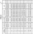
- the setting information 131 will be described by using FIG. 3.
- FIG. 3 is a diagram illustrating an example of the setting information according to the first embodiment.
- the setting information 131 is stored in the storage unit 13 manually or automatically before identification processing of dynamic IP addresses is carried out.
- the setting information 131 may be acquired from a secure sockets layer (SSL) server certificate.
- SSL secure sockets layer
- the setting information 131 includes items such as serial numbers, IP addresses, AS numbers, PTR records, and effective second level domains (e2LDs).
- the serial numbers are the numbers for identifying respective records.
- the PTR records are reverse lookup records of domain name system (DNS) and represent host names for the IP addresses.
- DNS domain name system
- the e2LDs are top level domain names and second level domain names included in the PTR records.
- the record of the serial number 26 of FIG. 3 represents that the AS number of the IP address "192.0.2.26” is “AS64496", the PTR record is "www.example.com”, and the e2LD is "example.com”.
- the control unit 14 controls the entire identification device 10.
- the control unit 14 is, for example, an electronic circuit such as a central processing unit (CPU) or a mirco processing unit (MPU) or an integrated circuit such as an application specific integrated circuit (ASIC) or a field programmable gate array (FPGA).
- the control unit 14 has an internal memory for storing programs, which define various processing procedures, and control data and executes processing by using the internal memory.
- the control unit 14 functions as various processing units when the various programs work.
- the control unit 14 has a specification unit 141 and an identification unit 142.
- the specification unit 141 specifies boundaries which divide rows of IP addresses sorted in a predetermined order, which are IP addresses included in IP address blocks input to the input unit 11, into a plurality of parts. For example, as illustrated in FIG. 4 , the specification unit 141 specifies a position 100a and a position 100b as boundaries.
- the setting information 131 is an example of predetermined information about IP addresses.
- the part referred to herein is part of the IP addresses included in the input IP address blocks and is an aggregate of the IP addresses maintaining the order and continuity of the sorted rows.
- the specification unit 141 sorts the IP addresses by the predetermined order.
- FIG. 4 is a diagram for describing management boundaries according to the first embodiment.
- the specification unit 141 uses the values of respective octets of the IP addresses considered as numerical values as keys and carries out sorting by the magnitude relation of the keys.
- the IP addresses are sorted in the ascending order of the keys.
- the specification unit 141 compares first information about a first IP address with second information about a second IP address, which is subsequent to the first IP address in the order of rows, and, if the similarity between the first information and the second information is equal to or less than a threshold value, specifies the position between the first IP address and the second IP address as a boundary.
- the specification unit 141 compares the values of predetermined items of two records which have continuous serial numbers in FIG. 4 and, if the similarity thereof is equal to or less than a predetermined value, specifies the position between the two continuous records as a boundary.
- the cases in which the similarity between the two comparison targets is equal to or less than the predetermined value include the cases in which the two comparison targets do not completely match.
- the specification unit 141 specifies the boundary based on the information with which whether the IP addresses have the same administrator or operator or not can be specified. In the present embodiment, if the AS numbers or e2LDs are different between two IP addresses, the specification unit 141 determines that the administrator or the operator of the two IP addresses are different from each other.
- the specification unit 141 specifies a position 100b between the record of the serial number 128 and the record of the serial number 129 as a boundary.
- the records before the position 100b and the records after the position 100b are divided into segments 1 and segments 2, respectively.
- the specification unit 141 specifies the position 100a between the record of the serial number 20 and the record of the serial number 21 as a boundary.
- the records before the position 100a and the records after the position 100a in the segment 1 are denoted by branch numbers and divided into segments 1-1 and segments 1-2, respectively.
- the specification unit 141 specifies boundaries based on the similarity of predetermined character strings included in predetermined information. Specifically, if the Jaro-Winkler distance (Reference Literature 1: William E.Winkler, "String Comparator Metrics and Enhanced Decision Rules in the Fellegi-Sunter Model of Record Linkage," Proceedings of the Section on Survey Research Methods, in American Statistical Association, pp.354--359, 1990 ) between a first character string, which is the host name of the first IP address excluding e2LD, and a second character string, which is the host name of the second IP address, which is subsequent to the first IP address in the order of the rows, excluding e2LD, is equal to or lower than a threshold value, the specification unit 141 specifies the position between the first IP address and the second IP address as a boundary.
- the host names are the PTR records.
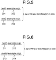
- FIG. 5 and FIG. 6 are diagrams for describing the comparison method of the character strings according to the first embodiment.
- a PTR record "test1.example.co.jp” includes a comparison-target character string 201 and an e2LD 202.
- a PTR record "test2.example.co.jp” includes a comparison-target character string 203 and an e2LD 204.
- the specification unit 141 calculates the Jaro-Winkler distance between the comparison-target character string 201 and the comparison-target character string 203 as 0.909.
- a PTR record "test1.example.co.jp” includes a comparison-target character string 211 and an e2LD 212.
- a PTR record "invalid.example.co.jp” includes a comparison-target character string 213 and an e2LD 214.
- the specification unit 141 calculates the Jaro-Winkler distance between the comparison-target character string 211 and the comparison-target character string 213 as 0.000.
- the specification unit 141 specifies a position 200a, a position 200b, a position 200c, a position 200d, a position 200e, and a position 200f as boundaries based on the Jaro-Winkler distances.
- FIG. 7 is a diagram for describing character string boundaries according to the first embodiment.
- the specification unit 141 specifies a position 200a between the record of the serial number 20 and the record of the serial number 21 as a boundary.
- the records before the position 200a and the records after the position 200a in segments 1-1 are further denoted by branch numbers and divided into segments 1-1-1 and segments 1-2-1, respectively.
- the Jaro-Winkler distance is an index which becomes 1 if two character strings completely match and becomes 0 if they do not match at all, and the Jaro-Winkler distance is defined based on a Jaro distance.
- the specification unit 141 calculates the Jaro distance ⁇ as Equation (1).
- the specification unit 141 calculates the Jaro-Winkler distance ⁇ n as Equation (2).
- ⁇ W 1 ⁇ c d + W 2 c r + W ⁇ ⁇ c ⁇ ⁇ c
- the combinations in the example of FIG. 7 for which the Jaro-Winkler distances of the character strings of comparison targets conceivably become equal to or less than the threshold value are, for example, the serial number 25 and the serial number 26, the serial number 20 and the serial number 27, the serial number 20 and the serial number 28, the serial number 20 and the serial number 29, and the serial number 128 and the serial number 129.
- the Jaro-Winkler distances of the character strings of comparison targets conceivably become larger than the threshold value in the ranges including, for example, the serial number 1 to the serial number 20 and the serial number 21 to the serial number 25.
- a network operator or an administrator of ISP, etc. collectively sets continuous IP addresses as dynamic IP addresses in many cases.
- character strings which are combinations of a common prefix and numerical values, which are different among IP addresses are set in the PTR records of the continuous IP addresses which are set collectively.
- the PTR records of the serial number 1 to the serial number 20 in FIG. 7 are combinations of a common prefix "host" with numbers.
- the identification unit 142 identifies the IP addresses included in the part as dynamic IP addresses. For example, if the number of IP addresses included in the part divided by the boundary is equal to or higher than a threshold value, the identification unit 142 identifies the IP addresses included in the part as dynamic IP addresses.
- the identification unit 142 identifies a part 300a, a part 300b, and a part 300c as dynamic IP addresses among the parts in which segments divided by boundaries match.
- FIG. 8 is a diagram for describing identification of types according to the first embodiment.
- the parameter N used in identification may be determined in advance by using IP address blocks, which are obviously static IP addresses or dynamic IP addresses, as training data.
- the parameter N may be determined by an administrator or may be automatically determined by the identification device 10.
- the identification device 10 determines the parameter N.
- the identification device 10 executes identification processing by the identification device 10 while the value of N is incremented from 1. Then, the identification device 10 calculates the sum of the number of static IP addresses erroneously identified as dynamic IP addresses and the number of dynamic IP addresses erroneously identified as static IP addresses. In this process, the identification device 10 employs the value of N that minimizes the calculated sum.
- FIG. 9 is a flow chart illustrating a processing flow of the identification device according to the first embodiment. As illustrated in FIG. 9 , first, the identification device 10 receives input of an IP address block (step S11).
- the identification device 10 reads the setting information 131, which corresponds to IP addresses included in the received IP address block, from the storage unit 13 (step S12). Then, the identification device 10 specifies a management boundary based on the setting information 131 (step S13).
- the management boundary is the boundary which is specified based on the information with which whether the IP addresses have the same administrator or operator or not can be specified. For example, the management boundary is the position before/after which the AS numbers or e2LDs of the sorted rows of the IP addresses are different.
- the identification device 10 specifies a character string boundary based on the setting information 131 (step S14).
- the character string boundary is the boundary specified based on the similarity of predetermined character strings.
- the character string boundary is the position at which the Jaro-Winkler distance of the e2LD-excluding parts of the PTR records of the IP addresses, which are sequential in the sorted row of the IP addresses, becomes equal to or less than a threshold value.
- the identification device 10 identifies the types of the IP addresses based on the management boundaries and the character string boundaries (step S15). For example, the types of the IP addresses are static IP addresses and dynamic IP addresses. If the number of the IP addresses included in the part of the sorted rows of the IP addresses divided by the management boundaries and the character string boundaries is equal to or higher than the threshold value, the identification device 10 identifies this part as dynamic IP addresses.
- the identification device 10 outputs identification results (step S16). For example, as the identification results, the identification device 10 outputs a list of the IP addresses which have been identified as dynamic IP addresses.
- the identification device 10 of the present embodiment specifies the boundaries which divide the rows of IP addresses, which are the IP addresses included in the IP address block and sorted in the predetermined order, into a plurality of parts based on predetermined information about IP addresses. If the part divided by the boundaries satisfy the predetermined condition, the identification unit 142 identifies the IP addresses, which are included in the part, as dynamic IP addresses. In this manner, the identification device 10 of the present embodiment identifies dynamic IP addresses without using specific keywords. Therefore, according to the identification device 10, dynamic IP addresses can be accurately identified.
- the identification device 10 compares first information about a first IP address with second information about a second IP address, which is subsequent to the first IP address in the order of rows, and, if the similarity between the first information and the second information is equal to or less than a threshold value, specifies the position between the first IP address and the second IP address as a boundary. In this manner, the identification device 10 specifies boundaries by focusing on the combinations of IP addresses, which are continuous in the order. Therefore, the identification device 10 does not have to evaluate all the combinations of IP addresses, and boundaries can be efficiently specified.
- the identification device 10 specifies boundaries based on the information with which whether the IP addresses have the same administrator or operator or not can be specified. Therefore, the identification device 10 can specify the dynamic IP addresses which are collectively managed by the same administrator or operator.
- the identification device 10 specifies boundaries based on the similarity of predetermined character strings included in predetermined information. Therefore, the identification device 10 can specify the dynamic IP addresses which use a common prefix in PTR records.
- the identification device 10 specifies the position between the first IP address and the second IP address as a boundary. In this manner, the identification device 10 can specify dynamic IP addresses by focusing on the part which highly possibly uses a common prefix in PTR records.
- the identification device 10 identifies the IP addresses included in the part as dynamic IP addresses. There is a tendency that the larger the number of the IP addresses in the segment, the higher the possibility that they are dynamic IP addresses. The identification device 10 can accurately identify dynamic IP addresses by using such a tendency.
- the example of the case in which the IP addresses, which are identification targets of the identification device 10, are IPv4 has been described.
- the IP addresses of the identification targets of the identification device 10 may be IPv6. Even if the IP addresses are IPv6, as well as the above described embodiment, the identification device 10 can carry out sorting by using the value of each sectioned part, which is considered as a numerical value, as a key.
- the identification device 10 may evaluate the similarity between the character strings by using an index other than the Jaro-Winkler distance.
- the identification device 10 can use the number or rate of the matching characters in the front side of two character strings as the similarity between the character strings.
- the constituent elements of the illustrated devices are functionally conceptual and are not necessarily required to be physically formed like the illustration.
- specific modes of distribution and integration of the devices are not limited to the illustration, but all or part thereof may be functionally or physically configured to be distributed or integrated in arbitrary units depending on various loads, usage conditions, etc.
- all or arbitrary part of the processing functions carried out in the devices may be realized by a CPU and a program(s) analyzed and executed by the CPU or may be realized as hardware by wired logic.
- all or part of the processing described to be automatically carried out may be manually carried out, or all or part of the processing described to be manually carried out may be automatically carried out by a publicly known method.
- processing procedures, control procedures, specific names, various data, and information including parameters described in the above described document or drawings may be arbitrarily changed unless otherwise specifically stated.
- the identification device 10 can be implemented by installing an identification program serving as packaged software or online software, which executes the above described identification processing, in a desired computer.
- an information processing device can be caused to function as the identification device 10 by executing the above described identification program by the information processing device.
- the information processing device referred to herein includes a personal computer of a desktop type or a laptop type.
- mobile communication terminals such as portable phones and personal handy-phone systems (PHSs), and slate terminals such as personal digital assistants (PDAs) fall within the category of the information processing device.
- PHSs personal handy-phone systems
- slate terminals such as personal digital assistants (PDAs) fall within the category of the information processing device.
- the identification device 10 can be implemented as an identification server device which uses a terminal device used by a user as a client and provides a service, which is related to the above described identification processing, to the client.
- the identification server device is implemented as a server device which provides an identification service which uses an IP address block as input and outputs a list of dynamic IP addresses.
- the identification server device may be implemented as a Web server or a cloud which provides a service related to the above described identification processing by outsourcing.
- FIG. 10 is a diagram illustrating an example of a computer which executes the identification program.
- a computer 1000 has, for example, a memory 1010 and a CPU 1020.
- the computer 1000 has a hard disk drive interface 1030, a disk drive interface 1040, a serial port interface 1050, a video adapter 1060, and a network interface 1070. These units are connected by a bus 1080.
- the memory 1010 includes a read only memory (ROM) 1011 and a RAM 1012.
- the ROM 1011 stores, for example, a boot program of, for example, a basic input output system (BIOS).
- BIOS basic input output system
- the hard disk drive interface 1030 is connected to a hard disk drive 1090.
- the disk drive interface 1040 is connected to a disk drive 1100.
- an attachable/detachable storage medium such as a magnetic disk or an optical disk is inserted in the disk drive 1100.
- the serial port interface 1050 is connected to, for example, a mouse 1110 and a keyboard 1120.
- the video adapter 1060 is connected to, for example, a display 1130.
- the hard disk drive 1090 stores, for example, an OS 1091, an application program 1092, a program module 1093, and program data 1094. More specifically, the program which defines the processings of the identification device 10 is implemented as the program module 1093, in which computer-executable codes are described.
- the program module 1093 is stored, for example, in the hard disk drive 1090.
- the program module 1093 for executing the processings which are similar to the functional configuration of the identification device 10 is stored in the hard disk drive 1090.
- the hard disk drive 1090 may be replaced by a SSD.
- setting data used in the processings of the above described embodiments is stored as the program data 1094, for example, in the memory 1010 or in the hard disk drive 1090.
- the CPU 1020 reads the program module 1093 and/or the program data 1094, which is stored in the memory 1010 or the hard disk drive 1090, to the RAM 1012 and executes the processing of the above described embodiment.
- program module 1093 and the program data 1094 is not limited to be stored in the hard disk drive 1090, but may be stored, for example, in an attachable/detachable storage medium and read by the CPU 1020 via the disk drive 1100 or the like.
- the program module 1093 and the program data 1094 may be stored in another computer connected via a network (local area network (LAN), wide area network (WAN), or the like). Then, the program module 1093 and the program data 1094 may be read from the other computer by the CPU 1020 via the network interface 1070.
- LAN local area network
- WAN wide area network
Landscapes
- Engineering & Computer Science (AREA)
- Computer Security & Cryptography (AREA)
- Computer Networks & Wireless Communication (AREA)
- Signal Processing (AREA)
- Computer Hardware Design (AREA)
- Computing Systems (AREA)
- General Engineering & Computer Science (AREA)
- Health & Medical Sciences (AREA)
- General Health & Medical Sciences (AREA)
- Virology (AREA)
- Data Exchanges In Wide-Area Networks (AREA)
Abstract
Description
- The present invention relates to an identification device, an identification method, and an identification program.
- Many of cyber attacks use malware-infected terminals, which are infected with malware. When measures against cyber attacks and malware-infected terminals are taken, internet protocol (IP) addresses are often handled as unique identifiers. Specifically, the IP addresses of malware-infected terminals are used as a blacklist or signatures in some cases, and the traffic transmitted from the IP addresses are handled as abnormal traffic in some cases. The IP address used by such a malware-infected terminal is a dynamic IP address assigned by an internet service provider (ISP) in many cases.
- Herein, if a dynamic IP address is assigned to a terminal, the IP address is not permanently used by the same terminal. For example, the IP address of the terminal is changed at the timing when a point-to-point protocol over Ethernet (PPPoE) session is reconnected, power is disconnected, or a change is made by ISP.
- Therefore, malware-infected terminals cannot be precisely specified with dynamic IP addresses. Therefore, a method for identifying dynamic IP addresses among IP addresses has been proposed in order to avoid using the dynamic IP addresses for specification of malware-infected terminals.
- For example, there has been proposed a method in which, if a PoinTeR (PTR) record of a target IP address includes a keyword designated in advance or part or all of the numerical values of first to fourth octets of the IP address, the IP address or a /24 address block including the IP address is identified as a dynamic IP address (for example, see
Non Patent Literatures 1 to 4). -
- Non Patent Literature 1: Yinglian Xie, Fang Yu, Kannan Achan, Eliot Gillum, Moises Goldszmidt and Ted Wobber, "How Dynamic are IP Addresses?," in SIGCOMM'07 Proceedings of the 2007 Conference on Applications, Technologies, Architectures, and Protocols for Computer Communications, pp.301-312, 2007.
- Non Patent Literature 2: Philipp Richter, Georgios Smaragdakis, David Plonka and Arthur Berger, "Beyond Counting:New Perspectives on the Active IPv4 Address Space," in IMC'16 Proceedings of the 2016 Internet Measurement Conference, pp.135-149, 2016.
- Non Patent Literature 3: Yu Jin, Esam Sharafuddin and Zhi-Li Zhang, "Identifying Dynamic IP Address Blocks Serendipitously through Background Scanning Traffic," in CoNEXT '07 Proceedings of the 2007 ACM CoNEXT conference, 2007.
- Non Patent Literature 4: Xue Cai and John Heidemann, "Understanding Block-level Address Usage in the Visible Internet," in SIGCOMM'10 Proceedings of the ACM SIGCOMM 2010 conference, pp.99-110, 2010.
- However, the conventional dynamic IP identifying methods are not capable of accurately identifying dynamic IP addresses in some cases. For example, if the PTR record of a dynamic IP address does not match any of designated keywords, it is difficult for the conventional methods to identify the dynamic IP address. Also, if a designated keyword is included in the PTR record of an IP address which is not a dynamic IP address, the conventional methods may erroneously identify the IP address, which is not a dynamic IP address, as a dynamic IP address.
- To solve a problem and to achieve an object, an identification device includes: a specification unit configured to specify a boundary dividing a row of an IP address, which is included in an IP address block and sorted by a predetermined order, into a plurality of parts based on predetermined information about the IP address; and an identification unit configured to identify the IP address included in the part as a dynamic IP address when the part divided by the boundary satisfies a predetermined condition.
- According to the present invention, dynamic IP addresses can be accurately identified.
-
-
FIG. 1 is a diagram illustrating an example of a configuration of an identification device according to a first embodiment. -
FIG. 2 is a diagram illustrating an example of IP address blocks according to the first embodiment. -
FIG. 3 is a diagram illustrating an example of setting information according to the first embodiment. -
FIG. 4 is a diagram for describing management boundaries according to the first embodiment. -
FIG. 5 is a diagram for describing a comparison method of character strings according to the first embodiment. -
FIG. 6 is a diagram for describing a comparison method of character strings according to the first embodiment. -
FIG. 7 is a diagram for describing character string boundaries according to the first embodiment. -
FIG. 8 is a diagram for describing identification of types according to the first embodiment. -
FIG. 9 is a flow chart illustrating a processing flow of the identification device according to the first embodiment. -
FIG. 10 is a diagram illustrating an example of a computer which executes an identification program. - Hereinafter, embodiments of an identification device, an identification method, and an identification program according to the present application will be described in detail based on drawings. Note that the present invention is not limited by the embodiments described below.
- First, a configuration of an identification device according to a first embodiment will be described by using
FIG. 1. FIG. 1 is a diagram illustrating an example of the configuration of the identification device according to the first embodiment. As illustrated inFIG. 1 , an identification device 10 has an input unit 11, an output unit 12, astorage unit 13, and acontrol unit 14. - The input unit 11 receives data input from a user. The input unit 11 is, for example, an input device such as a mouse or a keyboard. The output unit 12 outputs data, for example, by display on a screen. The output unit 12 is, for example, a display device such as a display. The input unit 11 and the output unit 12 may be an interface, which inputs/outputs data by communication with external devices.
- The input unit 11 receives input of IP address blocks as illustrated in
FIG. 2. FIG. 2 is a diagram illustrating an example of the IP address blocks according to the first embodiment. The IP address block is an aggregate of one or more IP addresses. - Herein, as illustrated in the record of a
serial number 1 ofFIG. 2 , the IP address block is expressed like "192.0.2.0/24". The IP address block "192.0.2.0/24" includes 256 IP addresses including "192.0.2" as higher 24 bits, in other words, a first octet to a third octet and including an arbitrary value as a lower 8 bits, in other words, a fourth octet. - Returning to
FIG. 1 , thestorage unit 13 is a storage device such as a hard disk drive (HDD), a solid state drive (SSD), or an optical disk. Thestorage unit 13 may be a data-rewritable semiconductor memory such as a random access memory (RAM), a flash memory, or a non volatile static random access memory (NVSRAM). Thestorage unit 13 stores an operating system (OS) and various programs, which are executed by the identification device 10. Furthermore, thestorage unit 13 stores various information used in execution of the programs. Thestorage unit 13stores setting information 131. - The
storage unit 13 stores the information about IP addresses as settinginformation 131. Herein, thesetting information 131 will be described by usingFIG. 3. FIG. 3 is a diagram illustrating an example of the setting information according to the first embodiment. Thesetting information 131 is stored in thestorage unit 13 manually or automatically before identification processing of dynamic IP addresses is carried out. For example, thesetting information 131 may be acquired from a secure sockets layer (SSL) server certificate. - As illustrated in
FIG. 3 , thesetting information 131 includes items such as serial numbers, IP addresses, AS numbers, PTR records, and effective second level domains (e2LDs). The serial numbers are the numbers for identifying respective records. The PTR records are reverse lookup records of domain name system (DNS) and represent host names for the IP addresses. The e2LDs are top level domain names and second level domain names included in the PTR records. - The record of the
serial number 26 ofFIG. 3 represents that the AS number of the IP address "192.0.2.26" is "AS64496", the PTR record is "www.example.com", and the e2LD is "example.com". - Returning to
FIG. 1 , thecontrol unit 14 controls the entire identification device 10. Thecontrol unit 14 is, for example, an electronic circuit such as a central processing unit (CPU) or a mirco processing unit (MPU) or an integrated circuit such as an application specific integrated circuit (ASIC) or a field programmable gate array (FPGA). Thecontrol unit 14 has an internal memory for storing programs, which define various processing procedures, and control data and executes processing by using the internal memory. Thecontrol unit 14 functions as various processing units when the various programs work. For example, thecontrol unit 14 has aspecification unit 141 and an identification unit 142. - Based on the setting
information 131, thespecification unit 141 specifies boundaries which divide rows of IP addresses sorted in a predetermined order, which are IP addresses included in IP address blocks input to the input unit 11, into a plurality of parts. For example, as illustrated inFIG. 4 , thespecification unit 141 specifies aposition 100a and aposition 100b as boundaries. The settinginformation 131 is an example of predetermined information about IP addresses. The part referred to herein is part of the IP addresses included in the input IP address blocks and is an aggregate of the IP addresses maintaining the order and continuity of the sorted rows. - As illustrated in
FIG. 4 , first, thespecification unit 141 sorts the IP addresses by the predetermined order.FIG. 4 is a diagram for describing management boundaries according to the first embodiment. According to the present embodiment, thespecification unit 141 uses the values of respective octets of the IP addresses considered as numerical values as keys and carries out sorting by the magnitude relation of the keys. In the example ofFIG. 4 , the IP addresses are sorted in the ascending order of the keys. - For example, the
specification unit 141 compares first information about a first IP address with second information about a second IP address, which is subsequent to the first IP address in the order of rows, and, if the similarity between the first information and the second information is equal to or less than a threshold value, specifies the position between the first IP address and the second IP address as a boundary. In other words, thespecification unit 141 compares the values of predetermined items of two records which have continuous serial numbers inFIG. 4 and, if the similarity thereof is equal to or less than a predetermined value, specifies the position between the two continuous records as a boundary. The cases in which the similarity between the two comparison targets is equal to or less than the predetermined value include the cases in which the two comparison targets do not completely match. - Specifically, the
specification unit 141 specifies the boundary based on the information with which whether the IP addresses have the same administrator or operator or not can be specified. In the present embodiment, if the AS numbers or e2LDs are different between two IP addresses, thespecification unit 141 determines that the administrator or the operator of the two IP addresses are different from each other. - For example, since the AS numbers are different between the records having
serial numbers 1 to 128 and the records havingserial numbers 129 or higher inFIG. 4 , thespecification unit 141 specifies aposition 100b between the record of theserial number 128 and the record of theserial number 129 as a boundary. In this case, the records before theposition 100b and the records after theposition 100b are divided intosegments 1 andsegments 2, respectively. - Furthermore, since e2LDs are different between the records of the
serial numbers 1 to 20 and the records of theserial numbers 21 and higher among the records of thesegment 1, thespecification unit 141 specifies theposition 100a between the record of theserial number 20 and the record of theserial number 21 as a boundary. In this case, the records before theposition 100a and the records after theposition 100a in thesegment 1 are denoted by branch numbers and divided into segments 1-1 and segments 1-2, respectively. - Furthermore, the
specification unit 141 specifies boundaries based on the similarity of predetermined character strings included in predetermined information. Specifically, if the Jaro-Winkler distance (Reference Literature 1: William E.Winkler, "String Comparator Metrics and Enhanced Decision Rules in the Fellegi-Sunter Model of Record Linkage," Proceedings of the Section on Survey Research Methods, in American Statistical Association, pp.354--359, 1990) between a first character string, which is the host name of the first IP address excluding e2LD, and a second character string, which is the host name of the second IP address, which is subsequent to the first IP address in the order of the rows, excluding e2LD, is equal to or lower than a threshold value, thespecification unit 141 specifies the position between the first IP address and the second IP address as a boundary. Herein, in the present embodiment, the host names are the PTR records. - A comparison method of the character strings by the
specification unit 141 will be described by usingFIG. 5 and FIG. 6. FIG. 5 and FIG. 6 are diagrams for describing the comparison method of the character strings according to the first embodiment. First, as illustrated inFIG. 5 , a PTR record "test1.example.co.jp" includes a comparison-target character string 201 and ane2LD 202. A PTR record "test2.example.co.jp" includes a comparison-target character string 203 and ane2LD 204. In this case, thespecification unit 141 calculates the Jaro-Winkler distance between the comparison-target character string 201 and the comparison-target character string 203 as 0.909. - As illustrated in
FIG. 6 , a PTR record "test1.example.co.jp" includes a comparison-target character string 211 and ane2LD 212. A PTR record "invalid.example.co.jp" includes a comparison-target character string 213 and ane2LD 214. In this case, thespecification unit 141 calculates the Jaro-Winkler distance between the comparison-target character string 211 and the comparison-target character string 213 as 0.000. - In this case, as illustrated in
FIG. 7 , thespecification unit 141 specifies aposition 200a, aposition 200b, aposition 200c, aposition 200d, aposition 200e, and aposition 200f as boundaries based on the Jaro-Winkler distances.FIG. 7 is a diagram for describing character string boundaries according to the first embodiment. - For example, since the Jaro-Winkler distance between the record of a
serial number 20 ofFIG. 7 and the record of aserial number 21 inFIG. 7 is equal to or less than the threshold value, thespecification unit 141 specifies aposition 200a between the record of theserial number 20 and the record of theserial number 21 as a boundary. In this case, the records before theposition 200a and the records after theposition 200a in segments 1-1 are further denoted by branch numbers and divided into segments 1-1-1 and segments 1-2-1, respectively. - Herein, the Jaro-Winkler distance is an index which becomes 1 if two character strings completely match and becomes 0 if they do not match at all, and the Jaro-Winkler distance is defined based on a Jaro distance. The
specification unit 141 calculates the Jaro distance Φ as Equation (1). Thespecification unit 141 calculates the Jaro-Winkler distance Φn as Equation (2).
- W 1: The number of characters of common prefix
- W 2: The weight on the characters of a second character string
- Wτ : The weight on replacement of characters
- d: The length of a first character string
- r: The length of the second character string
- τ: Replaced character string
- c: The number of matched characters when the positions of two characters are within

- For example, "test1" and "test2" of
FIG. 5 are different only by the one-digit number subsequent to the prefix "test". Therefore, the Jaro-Winkler distance between "test1" and "test2" is 0.909, which is an extremely large value. On the other hand, "test1" and "invalid" ofFIG. 6 do not contain matching characters at all, and the Jaro-Winkler distance thereof is therefore 0.000. - For example, if the threshold value of the Jaro-Winkler distance is 0.9000, the combinations in the example of
FIG. 7 for which the Jaro-Winkler distances of the character strings of comparison targets conceivably become equal to or less than the threshold value are, for example, theserial number 25 and theserial number 26, theserial number 20 and theserial number 27, theserial number 20 and theserial number 28, theserial number 20 and theserial number 29, and theserial number 128 and theserial number 129. On the other hand, the Jaro-Winkler distances of the character strings of comparison targets conceivably become larger than the threshold value in the ranges including, for example, theserial number 1 to theserial number 20 and theserial number 21 to theserial number 25. - Herein, in general, a network operator or an administrator of ISP, etc. collectively sets continuous IP addresses as dynamic IP addresses in many cases. For the sake of improving convenience in management or operation, in many cases, character strings which are combinations of a common prefix and numerical values, which are different among IP addresses, are set in the PTR records of the continuous IP addresses which are set collectively. For example, the PTR records of the
serial number 1 to theserial number 20 inFIG. 7 are combinations of a common prefix "host" with numbers. The Jaro-Winkler distances between the comparison-target character strings of such PTR records, which have a common prefix part and are different only by the number part, tend to become large. - Returning to
FIG. 1 , if the part divided by the boundary satisfies a predetermined condition, the identification unit 142 identifies the IP addresses included in the part as dynamic IP addresses. For example, if the number of IP addresses included in the part divided by the boundary is equal to or higher than a threshold value, the identification unit 142 identifies the IP addresses included in the part as dynamic IP addresses. - As illustrated in
FIG. 8 , the identification unit 142 identifies apart 300a, apart 300b, and apart 300c as dynamic IP addresses among the parts in which segments divided by boundaries match.FIG. 8 is a diagram for describing identification of types according to the first embodiment. For example, the identification unit 142 identifies the part in which the number of included IP addresses is equal to or more than a parameter N, which can be arbitrarily set, as dynamic IP addresses. In this case, if N=5, the identification unit 142 identifies thepart 300b as dynamic IP addresses since the number of the IP addresses included in thepart 300b corresponding to segments 1-2-1 is 5. - The parameter N used in identification may be determined in advance by using IP address blocks, which are obviously static IP addresses or dynamic IP addresses, as training data. The parameter N may be determined by an administrator or may be automatically determined by the identification device 10.
- Herein, an example of a case in which the identification device 10 determines the parameter N will be described. With respect to IP address blocks which are known whether they are dynamic IP addresses or not, the identification device 10 executes identification processing by the identification device 10 while the value of N is incremented from 1. Then, the identification device 10 calculates the sum of the number of static IP addresses erroneously identified as dynamic IP addresses and the number of dynamic IP addresses erroneously identified as static IP addresses. In this process, the identification device 10 employs the value of N that minimizes the calculated sum.
- A processing flow of the identification device 10 will be described by using
FIG. 9. FIG. 9 is a flow chart illustrating a processing flow of the identification device according to the first embodiment. As illustrated inFIG. 9 , first, the identification device 10 receives input of an IP address block (step S11). - Then, the identification device 10 reads the setting
information 131, which corresponds to IP addresses included in the received IP address block, from the storage unit 13 (step S12). Then, the identification device 10 specifies a management boundary based on the setting information 131 (step S13). Herein, the management boundary is the boundary which is specified based on the information with which whether the IP addresses have the same administrator or operator or not can be specified. For example, the management boundary is the position before/after which the AS numbers or e2LDs of the sorted rows of the IP addresses are different. - Then, the identification device 10 specifies a character string boundary based on the setting information 131 (step S14). The character string boundary is the boundary specified based on the similarity of predetermined character strings. For example, the character string boundary is the position at which the Jaro-Winkler distance of the e2LD-excluding parts of the PTR records of the IP addresses, which are sequential in the sorted row of the IP addresses, becomes equal to or less than a threshold value.
- The identification device 10 identifies the types of the IP addresses based on the management boundaries and the character string boundaries (step S15). For example, the types of the IP addresses are static IP addresses and dynamic IP addresses. If the number of the IP addresses included in the part of the sorted rows of the IP addresses divided by the management boundaries and the character string boundaries is equal to or higher than the threshold value, the identification device 10 identifies this part as dynamic IP addresses.
- Then, the identification device 10 outputs identification results (step S16). For example, as the identification results, the identification device 10 outputs a list of the IP addresses which have been identified as dynamic IP addresses.
- As described above, the identification device 10 of the present embodiment specifies the boundaries which divide the rows of IP addresses, which are the IP addresses included in the IP address block and sorted in the predetermined order, into a plurality of parts based on predetermined information about IP addresses. If the part divided by the boundaries satisfy the predetermined condition, the identification unit 142 identifies the IP addresses, which are included in the part, as dynamic IP addresses. In this manner, the identification device 10 of the present embodiment identifies dynamic IP addresses without using specific keywords. Therefore, according to the identification device 10, dynamic IP addresses can be accurately identified.
- For example, if the
parts FIG. 8 are to be identified as dynamic IP addresses by using a conventional method, keywords such as "host" and "test" have to be designated in advance. If such keywords are not designated in advance, it is difficult for conventional methods to identify dynamic IP addresses at the accuracy that is equivalent to or better than the present embodiment. It is not realistic to cover all the keywords which are used in the PTR records of dynamic IP addresses. Therefore, according to the method of the present embodiment, dynamic IP addresses can be easily and accurately identified compared with conventional methods. - The identification device 10 compares first information about a first IP address with second information about a second IP address, which is subsequent to the first IP address in the order of rows, and, if the similarity between the first information and the second information is equal to or less than a threshold value, specifies the position between the first IP address and the second IP address as a boundary. In this manner, the identification device 10 specifies boundaries by focusing on the combinations of IP addresses, which are continuous in the order. Therefore, the identification device 10 does not have to evaluate all the combinations of IP addresses, and boundaries can be efficiently specified.
- The identification device 10 specifies boundaries based on the information with which whether the IP addresses have the same administrator or operator or not can be specified. Therefore, the identification device 10 can specify the dynamic IP addresses which are collectively managed by the same administrator or operator.
- The identification device 10 specifies boundaries based on the similarity of predetermined character strings included in predetermined information. Therefore, the identification device 10 can specify the dynamic IP addresses which use a common prefix in PTR records.
- If the Jaro-Winkler distance between the first character string excluding the e2LD from the host name of the first IP address and the second character string excluding the e2LD from the host name of the second IP address, which is subsequent to the first IP address in the order of the rows, is equal to or lower than the threshold value, the identification device 10 specifies the position between the first IP address and the second IP address as a boundary. In this manner, the identification device 10 can specify dynamic IP addresses by focusing on the part which highly possibly uses a common prefix in PTR records.
- If the number of IP addresses included in the part divided by boundaries is equal to or higher than a threshold value, the identification device 10 identifies the IP addresses included in the part as dynamic IP addresses. There is a tendency that the larger the number of the IP addresses in the segment, the higher the possibility that they are dynamic IP addresses. The identification device 10 can accurately identify dynamic IP addresses by using such a tendency.
- In the above described embodiment, the example of the case in which the IP addresses, which are identification targets of the identification device 10, are IPv4 has been described. On the other hand, the IP addresses of the identification targets of the identification device 10 may be IPv6. Even if the IP addresses are IPv6, as well as the above described embodiment, the identification device 10 can carry out sorting by using the value of each sectioned part, which is considered as a numerical value, as a key.
- In the above described embodiment, the example of the case in which the similarity between the character strings is evaluated by the Jaro-Winkler distance has been described. On the other hand, the identification device 10 may evaluate the similarity between the character strings by using an index other than the Jaro-Winkler distance. For example, the identification device 10 can use the number or rate of the matching characters in the front side of two character strings as the similarity between the character strings.
- The constituent elements of the illustrated devices are functionally conceptual and are not necessarily required to be physically formed like the illustration. In other words, specific modes of distribution and integration of the devices are not limited to the illustration, but all or part thereof may be functionally or physically configured to be distributed or integrated in arbitrary units depending on various loads, usage conditions, etc. Furthermore, all or arbitrary part of the processing functions carried out in the devices may be realized by a CPU and a program(s) analyzed and executed by the CPU or may be realized as hardware by wired logic.
- Among the processings described in the present embodiment, all or part of the processing described to be automatically carried out may be manually carried out, or all or part of the processing described to be manually carried out may be automatically carried out by a publicly known method. Other than that, processing procedures, control procedures, specific names, various data, and information including parameters described in the above described document or drawings may be arbitrarily changed unless otherwise specifically stated.
- As an embodiment, the identification device 10 can be implemented by installing an identification program serving as packaged software or online software, which executes the above described identification processing, in a desired computer. For example, an information processing device can be caused to function as the identification device 10 by executing the above described identification program by the information processing device. The information processing device referred to herein includes a personal computer of a desktop type or a laptop type. Also, other than that, for example, smartphones, mobile communication terminals such as portable phones and personal handy-phone systems (PHSs), and slate terminals such as personal digital assistants (PDAs) fall within the category of the information processing device.
- Also, the identification device 10 can be implemented as an identification server device which uses a terminal device used by a user as a client and provides a service, which is related to the above described identification processing, to the client. For example, the identification server device is implemented as a server device which provides an identification service which uses an IP address block as input and outputs a list of dynamic IP addresses. In this case, the identification server device may be implemented as a Web server or a cloud which provides a service related to the above described identification processing by outsourcing.
-
FIG. 10 is a diagram illustrating an example of a computer which executes the identification program. Acomputer 1000 has, for example, amemory 1010 and aCPU 1020. Thecomputer 1000 has a harddisk drive interface 1030, adisk drive interface 1040, aserial port interface 1050, avideo adapter 1060, and anetwork interface 1070. These units are connected by abus 1080. - The
memory 1010 includes a read only memory (ROM) 1011 and aRAM 1012. TheROM 1011 stores, for example, a boot program of, for example, a basic input output system (BIOS). The harddisk drive interface 1030 is connected to ahard disk drive 1090. Thedisk drive interface 1040 is connected to adisk drive 1100. For example, an attachable/detachable storage medium such as a magnetic disk or an optical disk is inserted in thedisk drive 1100. Theserial port interface 1050 is connected to, for example, amouse 1110 and akeyboard 1120. Thevideo adapter 1060 is connected to, for example, adisplay 1130. - The
hard disk drive 1090 stores, for example, anOS 1091, anapplication program 1092, aprogram module 1093, andprogram data 1094. More specifically, the program which defines the processings of the identification device 10 is implemented as theprogram module 1093, in which computer-executable codes are described. Theprogram module 1093 is stored, for example, in thehard disk drive 1090. For example, theprogram module 1093 for executing the processings which are similar to the functional configuration of the identification device 10 is stored in thehard disk drive 1090. Note that thehard disk drive 1090 may be replaced by a SSD. - Also, setting data used in the processings of the above described embodiments is stored as the
program data 1094, for example, in thememory 1010 or in thehard disk drive 1090. Then, in accordance with needs, theCPU 1020 reads theprogram module 1093 and/or theprogram data 1094, which is stored in thememory 1010 or thehard disk drive 1090, to theRAM 1012 and executes the processing of the above described embodiment. - Note that the
program module 1093 and theprogram data 1094 is not limited to be stored in thehard disk drive 1090, but may be stored, for example, in an attachable/detachable storage medium and read by theCPU 1020 via thedisk drive 1100 or the like. Alternatively, theprogram module 1093 and theprogram data 1094 may be stored in another computer connected via a network (local area network (LAN), wide area network (WAN), or the like). Then, theprogram module 1093 and theprogram data 1094 may be read from the other computer by theCPU 1020 via thenetwork interface 1070. -
- 10
- IDENTIFICATION DEVICE
- 11
- INPUT UNIT
- 12
- OUTPUT UNIT
- 13
- STORAGE UNIT
- 14
- CONTROL UNIT
- 131
- SETTING INFORMATION
- 141
- SPECIFICATION UNIT
- 142
- IDENTIFICATION UNIT

Claims (8)
- An identification device comprising:a specification unit configured to specify a boundary dividing a row of an IP address, which is included in an IP address block and sorted by a predetermined order, into a plurality of parts based on predetermined information about the IP address; andan identification unit configured to identify the IP address included in the part as a dynamic IP address when the part divided by the boundary satisfies a predetermined condition.
- The identification device according to claim 1, wherein the specification unit compares first information about a first IP address and second information about a second IP address, which is subsequent to the first IP address in the order of the row, and, when a similarity between the first information and the second information is equal to or less than a threshold value, specifies a position between the first IP address and the second IP address as a boundary.
- The identification device according to claim 1 or 2, wherein the specification unit specifies the boundary based on information with which whether the IP address has a same administrator or operator can be specified.
- The identification device according to claim 1 or 2, wherein the specification unit specifies the boundary based on a similarity of a predetermined character string included in the predetermined information.
- The identification device according to claim 4, wherein, when a Jaro-Winkler distance between a first character string excluding an effective second level domain (e2LD) from a host name of a first IP address and a second character string excluding an e2LD from a host name of a second IP address, which is subsequent to the first IP address in the order of the row, is equal to or less than a threshold value, the specification unit specifies a position between the first IP address and the second IP address as the boundary.
- The identification device according to any one of claims 1 to 5, wherein, when the number of the IP address included in the part divided by the boundary is equal to or higher than a threshold value, the identification unit identifies the IP address included in the part as a dynamic IP address.
- An identification method executed by a computer, the identification method including:a specification process of specifying a boundary dividing a row of an IP address, which is included in an IP address block and sorted by a predetermined order, into a plurality of parts based on predetermined information about the IP address; andan identification process of identifying the IP address included in the part as a dynamic IP address when the part divided by the boundary satisfies a predetermined condition.
- An identification program for causing a computer to function as the identification device according to any one of claims 1 to 6.
Applications Claiming Priority (2)
| Application Number | Priority Date | Filing Date | Title |
|---|---|---|---|
| JP2018132725 | 2018-07-12 | ||
| PCT/JP2019/016345 WO2020012747A1 (en) | 2018-07-12 | 2019-04-16 | Identification device, identification method, and identification program |
Publications (3)
| Publication Number | Publication Date |
|---|---|
| EP3800838A1 true EP3800838A1 (en) | 2021-04-07 |
| EP3800838A4 EP3800838A4 (en) | 2022-03-02 |
| EP3800838B1 EP3800838B1 (en) | 2025-07-09 |
Family
ID=69141855
Family Applications (1)
| Application Number | Title | Priority Date | Filing Date |
|---|---|---|---|
| EP19833282.7A Active EP3800838B1 (en) | 2018-07-12 | 2019-04-16 | Identification device, identification method, and identification program |
Country Status (4)
| Country | Link |
|---|---|
| US (1) | US11405355B2 (en) |
| EP (1) | EP3800838B1 (en) |
| JP (1) | JP7028323B2 (en) |
| WO (1) | WO2020012747A1 (en) |
Family Cites Families (3)
| Publication number | Priority date | Publication date | Assignee | Title |
|---|---|---|---|---|
| US8856360B2 (en) * | 2007-06-22 | 2014-10-07 | Microsoft Corporation | Automatically identifying dynamic internet protocol addresses |
| US9338254B2 (en) * | 2013-01-09 | 2016-05-10 | Microsoft Corporation | Service migration across cluster boundaries |
| US9245121B1 (en) * | 2013-08-09 | 2016-01-26 | Narus, Inc. | Detecting suspicious network behaviors based on domain name service failures |
-
2019
- 2019-04-16 WO PCT/JP2019/016345 patent/WO2020012747A1/en not_active Ceased
- 2019-04-16 US US17/258,173 patent/US11405355B2/en active Active
- 2019-04-16 EP EP19833282.7A patent/EP3800838B1/en active Active
- 2019-04-16 JP JP2020530000A patent/JP7028323B2/en active Active
Also Published As
| Publication number | Publication date |
|---|---|
| JP7028323B2 (en) | 2022-03-02 |
| US20210281540A1 (en) | 2021-09-09 |
| EP3800838A4 (en) | 2022-03-02 |
| US11405355B2 (en) | 2022-08-02 |
| JPWO2020012747A1 (en) | 2020-12-17 |
| EP3800838B1 (en) | 2025-07-09 |
| WO2020012747A1 (en) | 2020-01-16 |
Similar Documents
| Publication | Publication Date | Title |
|---|---|---|
| US20250047717A1 (en) | Cybersecurity risk analysis and anomaly detection using active and passive external reconnaissance | |
| US11882137B2 (en) | Network security blacklist derived from honeypot statistics | |
| US11025674B2 (en) | Cybersecurity profiling and rating using active and passive external reconnaissance | |
| US20220014560A1 (en) | Correlating network event anomalies using active and passive external reconnaissance to identify attack information | |
| US12244616B2 (en) | Prioritizing assets using security metrics | |
| US11057411B2 (en) | Log analysis device, log analysis method, and log analysis program | |
| US20170373923A1 (en) | System and method for determining and forming a list of update agents | |
| US12542789B2 (en) | Malicious port scan detection using port profiles | |
| CN107743701A (en) | The global clustering to event based on Malware similitude and online degree of belief | |
| CN103180863A (en) | Computer system analysis method and apparatus | |
| EP3652668A1 (en) | Systems and methods for detecting vulnerabilities on servers | |
| WO2019134224A1 (en) | Network threat management method and device, computer device and storage medium | |
| US11388196B2 (en) | System and method for analyzing relationships between clusters of electronic devices to counter cyberattacks | |
| CN111083157B (en) | Method and device for processing message filtering rules | |
| US10949193B2 (en) | System and method of updating active and passive agents in a network | |
| CN106067879A (en) | The detection method of information and device | |
| EP3918762B1 (en) | Port scan detection | |
| US11928208B2 (en) | Calculation device, calculation method, and calculation program | |
| US20210243268A1 (en) | Ranking of enterprise devices using activity-based network profiles and functional characterization-based device clustering | |
| JP2019103069A (en) | Specific system, specific method and specific program | |
| EP3800838B1 (en) | Identification device, identification method, and identification program | |
| JPWO2017217247A1 (en) | Malignant event detection apparatus, malignant event detection method, and malignant event detection program | |
| US20200174868A1 (en) | Detection of event storms | |
| JP6669679B2 (en) | Classification device, classification method and classification program | |
| EP4702706A1 (en) | Iterative cross-product threat detection based on network telemetry relationships |
Legal Events
| Date | Code | Title | Description |
|---|---|---|---|
| STAA | Information on the status of an ep patent application or granted ep patent |
Free format text: STATUS: THE INTERNATIONAL PUBLICATION HAS BEEN MADE |
|
| PUAI | Public reference made under article 153(3) epc to a published international application that has entered the european phase |
Free format text: ORIGINAL CODE: 0009012 |
|
| STAA | Information on the status of an ep patent application or granted ep patent |
Free format text: STATUS: REQUEST FOR EXAMINATION WAS MADE |
|
| 17P | Request for examination filed |
Effective date: 20210104 |
|
| AK | Designated contracting states |
Kind code of ref document: A1 Designated state(s): AL AT BE BG CH CY CZ DE DK EE ES FI FR GB GR HR HU IE IS IT LI LT LU LV MC MK MT NL NO PL PT RO RS SE SI SK SM TR |
|
| AX | Request for extension of the european patent |
Extension state: BA ME |
|
| DAV | Request for validation of the european patent (deleted) | ||
| DAX | Request for extension of the european patent (deleted) | ||
| A4 | Supplementary search report drawn up and despatched |
Effective date: 20220202 |
|
| RIC1 | Information provided on ipc code assigned before grant |
Ipc: H04L 101/30 20220101ALN20220127BHEP Ipc: H04L 101/695 20220101ALN20220127BHEP Ipc: H04L 61/5061 20220101ALN20220127BHEP Ipc: H04L 61/4511 20220101AFI20220127BHEP |
|
| APBK | Appeal reference recorded |
Free format text: ORIGINAL CODE: EPIDOSNREFNE |
|
| APBN | Date of receipt of notice of appeal recorded |
Free format text: ORIGINAL CODE: EPIDOSNNOA2E |
|
| APBR | Date of receipt of statement of grounds of appeal recorded |
Free format text: ORIGINAL CODE: EPIDOSNNOA3E |
|
| APAF | Appeal reference modified |
Free format text: ORIGINAL CODE: EPIDOSCREFNE |
|
| APAF | Appeal reference modified |
Free format text: ORIGINAL CODE: EPIDOSCREFNE |
|
| APBT | Appeal procedure closed |
Free format text: ORIGINAL CODE: EPIDOSNNOA9E |
|
| REG | Reference to a national code |
Ref country code: DE Ref legal event code: R079 Free format text: PREVIOUS MAIN CLASS: H04L0012700000 Ipc: H04L0061451100 Ref country code: DE Ref legal event code: R079 Ref document number: 602019072384 Country of ref document: DE Free format text: PREVIOUS MAIN CLASS: H04L0012700000 Ipc: H04L0061451100 |
|
| GRAP | Despatch of communication of intention to grant a patent |
Free format text: ORIGINAL CODE: EPIDOSNIGR1 |
|
| STAA | Information on the status of an ep patent application or granted ep patent |
Free format text: STATUS: GRANT OF PATENT IS INTENDED |
|
| RIC1 | Information provided on ipc code assigned before grant |
Ipc: H04L 101/30 20220101ALN20250305BHEP Ipc: H04L 101/695 20220101ALN20250305BHEP Ipc: H04L 61/5061 20220101ALN20250305BHEP Ipc: H04L 9/40 20220101ALI20250305BHEP Ipc: H04L 61/4511 20220101AFI20250305BHEP |
|
| INTG | Intention to grant announced |
Effective date: 20250401 |
|
| RIC1 | Information provided on ipc code assigned before grant |
Ipc: H04L 101/30 20220101ALN20250324BHEP Ipc: H04L 101/695 20220101ALN20250324BHEP Ipc: H04L 61/5061 20220101ALN20250324BHEP Ipc: H04L 9/40 20220101ALI20250324BHEP Ipc: H04L 61/4511 20220101AFI20250324BHEP |
|
| GRAS | Grant fee paid |
Free format text: ORIGINAL CODE: EPIDOSNIGR3 |
|
| GRAA | (expected) grant |
Free format text: ORIGINAL CODE: 0009210 |
|
| STAA | Information on the status of an ep patent application or granted ep patent |
Free format text: STATUS: THE PATENT HAS BEEN GRANTED |
|
| AK | Designated contracting states |
Kind code of ref document: B1 Designated state(s): AL AT BE BG CH CY CZ DE DK EE ES FI FR GB GR HR HU IE IS IT LI LT LU LV MC MK MT NL NO PL PT RO RS SE SI SK SM TR |
|
| REG | Reference to a national code |
Ref country code: GB Ref legal event code: FG4D |
|
| REG | Reference to a national code |
Ref country code: CH Ref legal event code: EP |
|
| REG | Reference to a national code |
Ref country code: IE Ref legal event code: FG4D |
|
| REG | Reference to a national code |
Ref country code: DE Ref legal event code: R096 Ref document number: 602019072384 Country of ref document: DE |
|
| RAP4 | Party data changed (patent owner data changed or rights of a patent transferred) |
Owner name: NTT, INC. |
|
| REG | Reference to a national code |
Ref country code: NL Ref legal event code: MP Effective date: 20250709 |
|
| PG25 | Lapsed in a contracting state [announced via postgrant information from national office to epo] |
Ref country code: PT Free format text: LAPSE BECAUSE OF FAILURE TO SUBMIT A TRANSLATION OF THE DESCRIPTION OR TO PAY THE FEE WITHIN THE PRESCRIBED TIME-LIMIT Effective date: 20251110 |
|
| PG25 | Lapsed in a contracting state [announced via postgrant information from national office to epo] |
Ref country code: NL Free format text: LAPSE BECAUSE OF FAILURE TO SUBMIT A TRANSLATION OF THE DESCRIPTION OR TO PAY THE FEE WITHIN THE PRESCRIBED TIME-LIMIT Effective date: 20250709 |
|
| REG | Reference to a national code |
Ref country code: AT Ref legal event code: MK05 Ref document number: 1812942 Country of ref document: AT Kind code of ref document: T Effective date: 20250709 |
|
| PG25 | Lapsed in a contracting state [announced via postgrant information from national office to epo] |
Ref country code: IS Free format text: LAPSE BECAUSE OF FAILURE TO SUBMIT A TRANSLATION OF THE DESCRIPTION OR TO PAY THE FEE WITHIN THE PRESCRIBED TIME-LIMIT Effective date: 20251109 |
|
| PG25 | Lapsed in a contracting state [announced via postgrant information from national office to epo] |
Ref country code: NO Free format text: LAPSE BECAUSE OF FAILURE TO SUBMIT A TRANSLATION OF THE DESCRIPTION OR TO PAY THE FEE WITHIN THE PRESCRIBED TIME-LIMIT Effective date: 20251009 |
|
| REG | Reference to a national code |
Ref country code: LT Ref legal event code: MG9D |
|
| PG25 | Lapsed in a contracting state [announced via postgrant information from national office to epo] |
Ref country code: AT Free format text: LAPSE BECAUSE OF FAILURE TO SUBMIT A TRANSLATION OF THE DESCRIPTION OR TO PAY THE FEE WITHIN THE PRESCRIBED TIME-LIMIT Effective date: 20250709 |
|
| PG25 | Lapsed in a contracting state [announced via postgrant information from national office to epo] |
Ref country code: FI Free format text: LAPSE BECAUSE OF FAILURE TO SUBMIT A TRANSLATION OF THE DESCRIPTION OR TO PAY THE FEE WITHIN THE PRESCRIBED TIME-LIMIT Effective date: 20250709 |
|
| PG25 | Lapsed in a contracting state [announced via postgrant information from national office to epo] |
Ref country code: HR Free format text: LAPSE BECAUSE OF FAILURE TO SUBMIT A TRANSLATION OF THE DESCRIPTION OR TO PAY THE FEE WITHIN THE PRESCRIBED TIME-LIMIT Effective date: 20250709 |
|
| PG25 | Lapsed in a contracting state [announced via postgrant information from national office to epo] |
Ref country code: GR Free format text: LAPSE BECAUSE OF FAILURE TO SUBMIT A TRANSLATION OF THE DESCRIPTION OR TO PAY THE FEE WITHIN THE PRESCRIBED TIME-LIMIT Effective date: 20251010 |
|
| PG25 | Lapsed in a contracting state [announced via postgrant information from national office to epo] |
Ref country code: SE Free format text: LAPSE BECAUSE OF FAILURE TO SUBMIT A TRANSLATION OF THE DESCRIPTION OR TO PAY THE FEE WITHIN THE PRESCRIBED TIME-LIMIT Effective date: 20250709 |
|
| PG25 | Lapsed in a contracting state [announced via postgrant information from national office to epo] |
Ref country code: LV Free format text: LAPSE BECAUSE OF FAILURE TO SUBMIT A TRANSLATION OF THE DESCRIPTION OR TO PAY THE FEE WITHIN THE PRESCRIBED TIME-LIMIT Effective date: 20250709 |
|
| PG25 | Lapsed in a contracting state [announced via postgrant information from national office to epo] |
Ref country code: PL Free format text: LAPSE BECAUSE OF FAILURE TO SUBMIT A TRANSLATION OF THE DESCRIPTION OR TO PAY THE FEE WITHIN THE PRESCRIBED TIME-LIMIT Effective date: 20250709 Ref country code: BG Free format text: LAPSE BECAUSE OF FAILURE TO SUBMIT A TRANSLATION OF THE DESCRIPTION OR TO PAY THE FEE WITHIN THE PRESCRIBED TIME-LIMIT Effective date: 20250709 |
|
| PG25 | Lapsed in a contracting state [announced via postgrant information from national office to epo] |
Ref country code: RS Free format text: LAPSE BECAUSE OF FAILURE TO SUBMIT A TRANSLATION OF THE DESCRIPTION OR TO PAY THE FEE WITHIN THE PRESCRIBED TIME-LIMIT Effective date: 20251009 |
|
| PG25 | Lapsed in a contracting state [announced via postgrant information from national office to epo] |
Ref country code: ES Free format text: LAPSE BECAUSE OF FAILURE TO SUBMIT A TRANSLATION OF THE DESCRIPTION OR TO PAY THE FEE WITHIN THE PRESCRIBED TIME-LIMIT Effective date: 20250709 |
|
| REG | Reference to a national code |
Ref country code: DE Ref legal event code: R081 Ref document number: 602019072384 Country of ref document: DE Owner name: NTT, INC., JP Free format text: FORMER OWNER: NIPPON TELEGRAPH AND TELEPHONE CORPORATION, TOKYO, JP |
|
| PG25 | Lapsed in a contracting state [announced via postgrant information from national office to epo] |
Ref country code: SM Free format text: LAPSE BECAUSE OF FAILURE TO SUBMIT A TRANSLATION OF THE DESCRIPTION OR TO PAY THE FEE WITHIN THE PRESCRIBED TIME-LIMIT Effective date: 20250709 |
|
| PG25 | Lapsed in a contracting state [announced via postgrant information from national office to epo] |
Ref country code: DK Free format text: LAPSE BECAUSE OF FAILURE TO SUBMIT A TRANSLATION OF THE DESCRIPTION OR TO PAY THE FEE WITHIN THE PRESCRIBED TIME-LIMIT Effective date: 20250709 |
|
| PG25 | Lapsed in a contracting state [announced via postgrant information from national office to epo] |
Ref country code: IT Free format text: LAPSE BECAUSE OF FAILURE TO SUBMIT A TRANSLATION OF THE DESCRIPTION OR TO PAY THE FEE WITHIN THE PRESCRIBED TIME-LIMIT Effective date: 20250709 |
|
| PG25 | Lapsed in a contracting state [announced via postgrant information from national office to epo] |
Ref country code: CZ Free format text: LAPSE BECAUSE OF FAILURE TO SUBMIT A TRANSLATION OF THE DESCRIPTION OR TO PAY THE FEE WITHIN THE PRESCRIBED TIME-LIMIT Effective date: 20250709 |
|
| PG25 | Lapsed in a contracting state [announced via postgrant information from national office to epo] |
Ref country code: EE Free format text: LAPSE BECAUSE OF FAILURE TO SUBMIT A TRANSLATION OF THE DESCRIPTION OR TO PAY THE FEE WITHIN THE PRESCRIBED TIME-LIMIT Effective date: 20250709 Ref country code: SK Free format text: LAPSE BECAUSE OF FAILURE TO SUBMIT A TRANSLATION OF THE DESCRIPTION OR TO PAY THE FEE WITHIN THE PRESCRIBED TIME-LIMIT Effective date: 20250709 |
|
| PLBE | No opposition filed within time limit |
Free format text: ORIGINAL CODE: 0009261 |
|
| STAA | Information on the status of an ep patent application or granted ep patent |
Free format text: STATUS: NO OPPOSITION FILED WITHIN TIME LIMIT |