EP3800781A1 - Independent-speed-variable-frequency-generator-based constant frequency and narrow-band variable frequency power systems and methods - Google Patents
Independent-speed-variable-frequency-generator-based constant frequency and narrow-band variable frequency power systems and methods Download PDFInfo
- Publication number
- EP3800781A1 EP3800781A1 EP20189341.9A EP20189341A EP3800781A1 EP 3800781 A1 EP3800781 A1 EP 3800781A1 EP 20189341 A EP20189341 A EP 20189341A EP 3800781 A1 EP3800781 A1 EP 3800781A1
- Authority
- EP
- European Patent Office
- Prior art keywords
- frequency
- shaft
- generator
- equivalent
- limit
- Prior art date
- Legal status (The legal status is an assumption and is not a legal conclusion. Google has not performed a legal analysis and makes no representation as to the accuracy of the status listed.)
- Granted
Links
Images



Classifications
-
- H—ELECTRICITY
- H02—GENERATION; CONVERSION OR DISTRIBUTION OF ELECTRIC POWER
- H02P—CONTROL OR REGULATION OF ELECTRIC MOTORS, ELECTRIC GENERATORS OR DYNAMO-ELECTRIC CONVERTERS; CONTROLLING TRANSFORMERS, REACTORS OR CHOKE COILS
- H02P9/00—Arrangements for controlling electric generators for the purpose of obtaining a desired output
- H02P9/02—Details of the control
-
- H—ELECTRICITY
- H02—GENERATION; CONVERSION OR DISTRIBUTION OF ELECTRIC POWER
- H02P—CONTROL OR REGULATION OF ELECTRIC MOTORS, ELECTRIC GENERATORS OR DYNAMO-ELECTRIC CONVERTERS; CONTROLLING TRANSFORMERS, REACTORS OR CHOKE COILS
- H02P9/00—Arrangements for controlling electric generators for the purpose of obtaining a desired output
- H02P9/44—Control of frequency and voltage in predetermined relation, e.g. constant ratio
-
- H—ELECTRICITY
- H02—GENERATION; CONVERSION OR DISTRIBUTION OF ELECTRIC POWER
- H02P—CONTROL OR REGULATION OF ELECTRIC MOTORS, ELECTRIC GENERATORS OR DYNAMO-ELECTRIC CONVERTERS; CONTROLLING TRANSFORMERS, REACTORS OR CHOKE COILS
- H02P9/00—Arrangements for controlling electric generators for the purpose of obtaining a desired output
- H02P9/10—Control effected upon generator excitation circuit to reduce harmful effects of overloads or transients, e.g. sudden application of load, sudden removal of load, sudden change of load
-
- B—PERFORMING OPERATIONS; TRANSPORTING
- B64—AIRCRAFT; AVIATION; COSMONAUTICS
- B64D—EQUIPMENT FOR FITTING IN OR TO AIRCRAFT; FLIGHT SUITS; PARACHUTES; ARRANGEMENT OR MOUNTING OF POWER PLANTS OR PROPULSION TRANSMISSIONS IN AIRCRAFT
- B64D33/00—Arrangement in aircraft of power plant parts or auxiliaries not otherwise provided for
-
- H—ELECTRICITY
- H02—GENERATION; CONVERSION OR DISTRIBUTION OF ELECTRIC POWER
- H02P—CONTROL OR REGULATION OF ELECTRIC MOTORS, ELECTRIC GENERATORS OR DYNAMO-ELECTRIC CONVERTERS; CONTROLLING TRANSFORMERS, REACTORS OR CHOKE COILS
- H02P29/00—Arrangements for regulating or controlling electric motors, appropriate for both AC and DC motors
- H02P29/02—Providing protection against overload without automatic interruption of supply
- H02P29/024—Detecting a fault condition, e.g. short circuit, locked rotor, open circuit or loss of load
- H02P29/0241—Detecting a fault condition, e.g. short circuit, locked rotor, open circuit or loss of load the fault being an overvoltage
-
- H—ELECTRICITY
- H02—GENERATION; CONVERSION OR DISTRIBUTION OF ELECTRIC POWER
- H02P—CONTROL OR REGULATION OF ELECTRIC MOTORS, ELECTRIC GENERATORS OR DYNAMO-ELECTRIC CONVERTERS; CONTROLLING TRANSFORMERS, REACTORS OR CHOKE COILS
- H02P9/00—Arrangements for controlling electric generators for the purpose of obtaining a desired output
- H02P9/14—Arrangements for controlling electric generators for the purpose of obtaining a desired output by variation of field
Definitions
- This disclosure is generally related to the field of power distribution and, in particular, to independent speed variable frequency (ISVF) generator-based constant frequency and narrowband power distribution.
- ISVF independent speed variable frequency
- Induction generators may be used in a power distribution system, such as in aircrafts and other vehicles, to provide an alternating current (AC) power signal for use by various AC loads.
- the AC loads typically have power frequency requirements that limit the AC power signal to a constant frequency or to a frequency band that is narrower than a typical operational frequency band of a prime mover, such as an engine.
- a constant speed drive (or some other type of variable speed transmission) may be positioned between the prime mover and a shaft of the generator.
- Constant speed drives may be complex, heavy, and/or bulky. As such, they may be inappropriate for some applications, particularly with respect to aircraft applications. Other disadvantages may exist.
- a system includes a prime mover configured to rotate a shaft.
- the system further includes an ISVF generator configured to convert torque from the shaft to an AC power signal, where the ISVF generator has one or more pole pairs, and where an equivalent shaft frequency equals a shaft frequency of the shaft multiplied by a number of the pole pairs.
- the system includes an AC bus having a lower frequency limit and an upper frequency limit.
- the system further includes a generator control unit configured to set a generator output frequency of the ISVF generator equal to the lower frequency limit when the equivalent shaft frequency is less than the lower frequency limit, to set the generator output frequency of the ISVF generator equal to the upper frequency limit when the equivalent shaft frequency is greater than the upper frequency limit, and to set the generator output frequency of the ISVF generator equal to the equivalent shaft frequency when the equivalent shaft frequency is greater than or equal to the lower frequency limit and less than or equal to the upper frequency limit.
- a generator control unit configured to set a generator output frequency of the ISVF generator equal to the lower frequency limit when the equivalent shaft frequency is less than the lower frequency limit, to set the generator output frequency of the ISVF generator equal to the upper frequency limit when the equivalent shaft frequency is greater than or equal to the lower frequency limit and less than or equal to the upper frequency limit.
- the generator control unit is configured to generate an excitation signal to control the ISVF generator, where an equivalent excitation frequency equals an excitation frequency of the excitation signal multiplied by the number of pole pairs.
- setting the generator output frequency equal to the lower frequency limit includes setting the equivalent excitation frequency to a difference of the lower frequency limit and the equivalent shaft frequency
- setting the generator output frequency equal to the upper frequency limit includes setting the equivalent excitation frequency of the excitation signal equal to a difference of the upper frequency limit and the equivalent shaft frequency
- setting the generator output frequency equal to the equivalent shaft frequency includes setting the equivalent excitation frequency of the excitation signal to zero.
- the system includes a coupler positioned between the prime mover and the shaft and configured to convert a second torque associated with the prime mover to the torque associated with the shaft.
- the coupler includes a fixed ratio gear coupling, a belt, or a combination thereof.
- the prime mover is configured to rotate the shaft without any constant speed drive device coupled therebetween.
- the system includes a set of AC loads electrically connected to the AC bus, where the lower frequency limit and the upper frequency limit are determined at least partially based on operational requirements of the set of AC loads.
- the system may include an alternating-current-direct-current (AC/DC) converter electrically connected to the AC bus and a direct current (DC) bus electrically connected to the AC/DC converter, where the AC/DC converter is configured to convert the AC power signal on the AC bus to a DC power signal on the DC bus.
- AC/DC alternating-current-direct-current
- DC direct current
- the prime mover is an aircraft engine.
- a method in an example, includes rotating a shaft using a prime mover. The method further includes converting torque from the shaft to an AC power signal using an ISVF generator, where the ISVF generator has one or more pole pairs, and where an equivalent shaft frequency equals a shaft frequency of the shaft multiplied by a number of the pole pairs. The method further includes applying the AC power signal to an AC bus having a lower frequency limit and an upper frequency limit. The method also includes setting a generator output frequency of the ISVF generator equal to the lower frequency limit when the equivalent shaft frequency is less than the lower frequency limit. The method includes setting the generator output frequency of the ISVF generator equal to the upper frequency limit when the equivalent shaft frequency is greater than the upper frequency limit. The method further includes setting the generator output frequency of the ISVF generator equal to the equivalent shaft frequency when the equivalent shaft frequency is between the lower frequency limit and the upper frequency limit.
- the method includes generating an excitation signal to control the ISVF generator, where an equivalent excitation frequency equals an excitation frequency of the excitation signal multiplied by the number of pole pairs, where setting the generator output frequency equal to the lower frequency limit comprises setting the equivalent excitation frequency to a difference of the lower frequency limit and the equivalent shaft frequency, where setting the generator output frequency equal to the upper frequency limit comprises setting the equivalent excitation frequency of the excitation signal equal to a difference of the upper frequency limit and the equivalent shaft frequency, and where setting the generator output frequency equal to the equivalent shaft frequency comprises setting the equivalent excitation frequency of the excitation signal to zero.
- the method includes converting second torque associated with the prime mover to the torque associated with the shaft using a coupler.
- the coupler includes a fixed ratio gear coupling, a belt, or a combination thereof.
- rotating the shaft is performed without any constant speed drive device coupled between the shaft and the prime mover.
- an AC/DC converter is electrically connected to the AC bus, and where a DC bus is electrically connected to the AC/DC converter.
- the method may include converting, at the AC/DC converter, the AC power signal on the AC bus to a DC power signal on the DC bus.
- a system in an example, includes a prime mover configured to rotate a shaft.
- the system further includes an ISVF generator configured to convert torque from the shaft to an AC power signal, where the ISVF generator has one or more pole pairs, and where an equivalent shaft frequency equals a shaft frequency of the shaft multiplied by a number of the pole pairs.
- the system further includes an AC bus and a generator control unit configured to generate an excitation signal to control the ISVF generator, where an equivalent excitation frequency equals an excitation frequency of the excitation signal multiplied by the number of pole pairs, and where the generator control unit maintains a constant generator output frequency by setting the equivalent excitation frequency equal to a difference between the constant generator output frequency and the equivalent shaft frequency.
- the system includes a coupler positioned between the prime mover and the shaft and configured to convert second torque associated with the prime mover to the torque associated with the shaft, where the coupler includes a fixed ratio gear coupling, a belt, or a combination thereof.
- the prime mover is configured to rotate the shaft without any constant speed drive device coupled therebetween.
- the system includes a set of AC loads electrically connected to the AC bus, where the constant generator output frequency is determined at least partially based on operational requirements of the set of AC loads.
- the system includes an AC/DC converter electrically connected to the AC bus, and a DC bus electrically connected to the AC/DC converter, where the AC/DC converter is configured to convert the AC power signal on the AC bus to a DC power signal on the DC bus.
- an independent speed variable frequency (ISVF)-generator-based power system 100 is depicted.
- the system 100 may be configured to generate and distribute power within a frequency band that, for a given range of shaft speeds, is narrower than would be generated using a typical induction generator without a constant speed drive device or other type of transmission device.
- ISVF independent speed variable frequency
- the system 100 may include a prime mover 102.
- the prime mover 102 may be an aircraft engine or another type of vehicle engine.
- the prime mover 102 may be attached to a coupler 104.
- the coupler 104 may include a fixed gear ratio coupler, a belt coupler, or a combination thereof, and may be configured to convert torque 129 from the prime mover 102 to torque 130 on a shaft 106.
- the coupler 104 may differ from a constant speed device in that the torque transfer ratios of the coupler 104 may be fixed, rather than variable.
- the shaft 106 may be attached to an ISVF generator 108. By using an ISVF generator 108 instead of a typical induction generator, the system 100 may omit any constant speed drive device between the prime mover 102 and the shaft 106.
- the ISVF generator 108 may be configured to convert torque 130 from the shaft 106 to an AC power signal 132.
- the ISVF generator 108 may generate the AC power signal 132 such that a frequency of the AC power signal 132 is independent of a shaft speed of the shaft 106.
- An example of an ISVF generator 108 usable with the system 100 is described further in U.S. Patent Application No. 15/819,919, filed on November 21, 2017 , published as U.S. Patent App. Publication No. 2019/0158002 , and entitled "Independent Speed Variable Frequency Alternating Current Generator," the contents of which are hereby incorporated by reference in their entirety.
- the ISVF generator 108 may have one or more pole pairs 109.
- FIG. 1 depicts the ISVF generator 108 as having two pole pairs 109 (i.e., four poles). However, more or fewer than two pole pairs are possible and consistent with the disclosure.
- the number of pole pairs 109 may act as a multiplier between a frequency of the shaft 106 and a frequency of the AC power signal 132. As such, the shaft 106 may be associated with an equivalent shaft frequency that equals a shaft frequency of the shaft 106 multiplied by the number of pole pairs 109.
- the system 100 may include a generator control unit (GCU) 110.
- the generator control unit 110 may be configured to generate an excitation signal 134 to control the ISVF generator 108.
- the excitation signal 134 may be used by the ISVF generator 108 to generate a rotating magnetic flux at a rotor of the ISVF generator 108, resulting in a frequency of the AC power signal 132 being an algebraic sum of the frequency of the shaft 106 and a frequency of the excitation signal 134.
- the number of pole pairs 109 of the ISVF generator 108 may also affect the contribution of the excitation signal 134 to the AC power signal 132.
- an equivalent excitation frequency of the excitation signal 134 may equal an excitation frequency of the excitation signal 134 multiplied by the number of pole pairs 109.
- the ISVF generator 108 may be coupled to an AC bus 112.
- a set of AC loads 114 may be coupled to and configured to receive power from the AC bus 112.
- the set of AC loads 114 may have operational requirements such that the set of AC loads 114 is adapted to operate within an operational frequency band having a lower frequency limit and an upper frequency limit.
- the operational frequency band may be narrower than an operating frequency band associated with the prime mover 102.
- An AC/DC converter 116 may be coupled to the AC bus 112.
- the AC/DC converter 116 may be configured to convert the AC power signal 132 into a DC power signal 136 and to power a DC bus 118 using the DC power signal 136.
- a set of DC loads 120 may be coupled to the DC bus 118.
- a direct-current to alternating-current (DC/AC) converter 122 may be coupled to the DC bus 118.
- the DC/AC converter 122 may be configured to convert the DC power signal 136 to a second AC power signal 134 to power a second AC bus 124.
- a set of AC loads 126 may be coupled to the second AC bus 124.
- the second set of AC loads 126 may have different operational frequency and voltage requirements than the set of AC loads 114.
- the second set of AC loads 126 corresponds to motor loads, such as for actuating flight surfaces, etc.
- the generator control unit 110 may be configured to control the ISVF generator 108 to generate the AC power signal 132 to fall within a frequency band, having a lower frequency limit and an upper frequency limit, that, for a given range of shaft speeds, is narrower than would be generated using a typical induction generator.
- the generator control unit 110 may be configured to set a generator output frequency of the ISVF generator 108 equal to the lower frequency limit in response to the equivalent shaft frequency (e.g., the shaft frequency multiplied by the number of pole pairs 109) being less than the lower frequency limit.
- the generator control unit 110 may be configured to set the generator output frequency of the ISVF generator 108 equal to the upper frequency limit in response to the equivalent shaft frequency being greater than the upper frequency limit. In response to the equivalent shaft frequency being greater than or equal to the lower frequency limit and less than or equal to the upper frequency limit, the generator control unit 110 may be configured to set the generator output frequency of the ISVF generator 108 equal to the equivalent shaft frequency. In a second configuration, the generator control unit 110 may simply maintain a constant generator output frequency rather than narrowing the frequency band.
- a benefit of the system 100 is that by using the ISVF generator 108 to narrow a frequency range of the AC power signal relative to a rotational frequency range of the shaft, the system 100 may omit complex, heavy, and/or bulky equipment, such as constant speed drive, between the shaft and the ISVF generator 108.
- the generator control unit 110 may limit a generator output frequency to a constant generator output frequency that corresponds to operational requirements of the set of AC loads 114.
- Another benefit is that, in cases where the AC bus 112 may support a range of frequencies, by narrowing the generator output frequency 504 (shown in FIG. 5 ) to a range having a lower frequency limit and an upper frequency limit, the load equipment may be lighter and less complex due to a favorable operation condition of a narrow frequency band as described herein.
- Other benefits and advantages may exist.
- FIGS. 2 and 3 describe the concept of an equivalent shaft frequency 210 and an equivalent excitation frequency 308. These frequencies depend on the number of pole pairs 109 associated with the ISVF generator 108. In cases where there is only one pole pair, the equivalent shaft frequency 210 and the equivalent excitation frequency 308 are equal to a shaft frequency 208 and an excitation frequency 306, respectively.
- a graph is depicted that relates a shaft frequency band 202 to an equivalent shaft frequency band 204 and to an AC output signal frequency band 206.
- a shaft frequency 208 may fall within the shaft frequency band 202.
- the shaft frequency 208 may represent the frequency at which a prime mover (e.g., the prime mover 102) rotates a shaft (e.g., the shaft 106).
- the shaft frequency band 202 may be bounded between a lower shaft frequency limit 214, representing the lowest operational frequency at which the prime mover will rotate the shaft, and an upper shaft frequency limit 216, representing the highest operational frequency at which the prime mover will rotate the shaft.
- FIG. 2 depicts the lower shaft frequency limit 214 as being 100 Hz and the upper shaft frequency limit 216 as being 300 Hz.
- the equivalent shaft frequency band 204 may be equal to the number of pole pairs of an ISVF generator (e.g., the ISVF generator 108) multiplied by the shaft frequency band 202.
- an ISVF generator e.g., the ISVF generator 1028
- there may be two pole pairs such that if the shaft frequency 208 is about 175 Hz, then an equivalent shaft frequency 210 is about 350 Hz.
- a lower equivalent shaft frequency limit 218 may be about 200 Hz and an upper equivalent shaft frequency limit 220 may be 600 Hz.
- any number of pole pairs may be used.
- an ISVF generator e.g., the ISVF generator 108 may be controlled through an excitation signal (e.g., the excitation signal 134) to generate the narrower AC output signal frequency band 206.
- the AC output signal frequency band 206 may have a lower frequency limit 222 that is greater than the lower equivalent shaft frequency limit 218.
- the AC output signal frequency band 206 may have an upper frequency limit 224 that is less than the upper equivalent shaft frequency limit 220.
- the AC output signal frequency band 206 may be limited to meet operational requirements of AC loads.
- an excitation frequency band 302 to an equivalent excitation frequency band 304.
- An excitation signal (e.g., the excitation signal 134) may be applied to the field windings on a rotor of an ISVF generator (e.g., the ISVF generator 108) to effectively increase or decrease a frequency of an output power signal.
- the excitation signal may have an excitation frequency 306 that falls within the excitation frequency band 302. Because the number of pole pairs associated with the ISVF generator affects the output frequency, the equivalent excitation frequency band 304 may be equal to the excitation frequency band 302 multiplied by the number of pole pairs. Likewise, an equivalent excitation frequency 308 may be equal to the excitation frequency 306 multiplied by the number of pole pairs.
- a graph 400 depicts a functional relationship 402 between power capacity requirement S Excit of an excitation signal and a frequency f Excit of the excitation signal. While the description in FIG. 4 may apply to a single pole pair system, the concepts may be expanded to multiple pole pairs as would be understood by persons of ordinary skill in the art, having the benefit of this application. As shown in the graph 400, as the frequency f Excit moves away from zero, the excitation signal may need more power S Excit in order to maintain a constant power output from an ISVF generator. Analysis shows that this relationship can be roughly represented by a conic section curve as shown.
- the excitation signal need only provide sufficient power to compensate for power loss at rotor windings (e.g., yo).
- the excitation frequency f Excit is positive when the generator shaft speed is lower than the generator output frequency. In this case, the excitation source provides an apparent power to the stator windings.
- the excitation frequency f Excit is negative when the generator shaft speed is higher than the generator output frequency. In this case, the excitation source sinks an apparent power from the generator shaft. The further the deviation (between excitation frequency f Excit and a generator rated output frequency) is, the higher the power capacity S Excit of excitation signal may be.
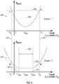
- a first graph 500 depicts power requirements associated with a first configuration of the system 100 and is compared to a second graph 550 depicting power requirements associated with a second configuration of the system 100.
- the first configuration may correspond to a constant frequency output and the second configuration may correspond to a narrowed frequency band output.
- a generator control unit e.g., the generator control unit 110
- the generator output frequency 504 may equal the algebraic sum of the shaft frequency 208 and the excitation frequency 306:
- F Gen f Shaft t + f Excit t
- the constant generator output frequency configuration depicted in the first graph 500 may be appropriate when the range of shaft frequencies is relatively narrow.
- the configuration depicted in the second graph 550 may be more appropriate.
- a generator control unit e.g., the generator control unit 110
- the generator output frequency 502 may be held between a lower frequency limit 222 and an upper frequency limit 224: F min ⁇ F Gen ⁇ F max
- the generator output frequency 502 may be set equal to the shaft frequency 208 by setting the excitation frequency 306 of the excitation signal to zero. If the shaft frequency 208 is less than the lower frequency limit 222, then the generator output frequency 502 may be set equal to the lower frequency limit 222 by setting the excitation frequency 306 to a difference of the lower frequency limit 222 and the shaft frequency 208.
- the generator output frequency 502 may be set equal to the equivalent shaft frequency 210 by setting the equivalent excitation frequency 308 of the excitation signal to zero. If the equivalent shaft frequency 210 is less than the lower frequency limit 222, then the generator output frequency 502 may be set equal to the lower frequency limit 222 by setting the equivalent excitation frequency 308 to a difference of the lower frequency limit 222 and the equivalent shaft frequency 210.
- the second graph 550 As shown in the second graph 550, as the shaft frequency shifts away from the generator output frequency 502, more a constant level of power is allocated to the excitation signal while the shaft frequency is between the lower frequency limit 222 and the upper frequency limit 224. Thus, a relatively low power 508 may be used for the same range of shaft frequencies.
- the narrow band generator output frequency configuration depicted in the second graph 550 may be appropriate when the range of shaft frequencies is relatively broad and AC loads are able to operate with frequencies between the lower frequency limit 222 and the upper frequency limit 224.
- the method 600 may include rotating a shaft using a prime mover, at 602.
- the shaft 106 may be rotated using the prime mover 102.
- the method 600 may further include converting torque from the shaft to an AC power signal using an ISVF generator, where the ISVF generator has one or more pole pairs, and where an equivalent shaft frequency equals a shaft frequency of the shaft multiplied by a number of the pole pairs, at 604.
- the torque 130 from the shaft 106 may be converted to the AC power signal 132 using the ISVF generator 108.
- the method 600 may also include converting a second torque associated with the prime mover to the torque associated with the shaft using a coupler, at 606.
- the second torque 129 may be converted to the torque 130 using the coupler 104.
- the method 600 may further include generating an excitation signal to control the ISVF generator, where an equivalent excitation frequency equals an excitation frequency of the excitation signal multiplied by the number of pole pairs, at 608.
- the generator control unit 110 may generate the excitation signal 134.
- the method 600 may also include applying the AC power signal to an AC bus having a lower frequency limit and an upper frequency limit, at 610.
- the AC power signal 132 may be applied to the AC bus 112.
- the method 600 may include setting a generator output frequency of the ISVF generator equal to the lower frequency limit when the equivalent shaft frequency is less than the lower frequency limit, at 612. Setting the generator output frequency of the ISVF generator equal to the lower frequency limit may include setting the equivalent excitation frequency to a difference of the lower frequency limit and the equivalent shaft frequency, at 614.
- the method 600 may further include setting the generator output frequency of the ISVF generator equal to the upper frequency limit when the equivalent shaft frequency is greater than the upper frequency limit, at 616.
- Setting the generator output frequency equal to the upper frequency limit may include setting the equivalent excitation frequency of the excitation signal equal to a difference of the upper frequency limit and the equivalent shaft frequency, at 618.
- the method 600 may include setting the generator output frequency of the ISVF generator equal to the equivalent shaft frequency when the equivalent shaft frequency is between the lower frequency limit and the upper frequency limit, at 620. Setting the generator output frequency equal to the equivalent shaft frequency comprises setting the equivalent excitation frequency of the excitation signal to zero, at 622.
- a benefit of the method 600 is that by using an ISVF generator to narrow a frequency range of an AC power signal relative to a rotational frequency range of a shaft, complex, heavy, and/or bulky equipment, such as constant speed drive, may be omitted between the shaft and the ISVF generator. Other advantages may exist.
Landscapes
- Engineering & Computer Science (AREA)
- Power Engineering (AREA)
- Aviation & Aerospace Engineering (AREA)
- Control Of Eletrric Generators (AREA)
Abstract
Description
- This disclosure is generally related to the field of power distribution and, in particular, to independent speed variable frequency (ISVF) generator-based constant frequency and narrowband power distribution.
- Induction generators may be used in a power distribution system, such as in aircrafts and other vehicles, to provide an alternating current (AC) power signal for use by various AC loads. The AC loads typically have power frequency requirements that limit the AC power signal to a constant frequency or to a frequency band that is narrower than a typical operational frequency band of a prime mover, such as an engine.
- In a typical power distribution system, in order to achieve a constant generator output frequency, a constant speed drive (or some other type of variable speed transmission) may be positioned between the prime mover and a shaft of the generator. Constant speed drives may be complex, heavy, and/or bulky. As such, they may be inappropriate for some applications, particularly with respect to aircraft applications. Other disadvantages may exist.
- Disclosed herein are systems and methods that may overcome one or more of the disadvantages of typical power distribution systems. In an example, a system includes a prime mover configured to rotate a shaft. The system further includes an ISVF generator configured to convert torque from the shaft to an AC power signal, where the ISVF generator has one or more pole pairs, and where an equivalent shaft frequency equals a shaft frequency of the shaft multiplied by a number of the pole pairs. The system includes an AC bus having a lower frequency limit and an upper frequency limit. The system further includes a generator control unit configured to set a generator output frequency of the ISVF generator equal to the lower frequency limit when the equivalent shaft frequency is less than the lower frequency limit, to set the generator output frequency of the ISVF generator equal to the upper frequency limit when the equivalent shaft frequency is greater than the upper frequency limit, and to set the generator output frequency of the ISVF generator equal to the equivalent shaft frequency when the equivalent shaft frequency is greater than or equal to the lower frequency limit and less than or equal to the upper frequency limit.
- In some examples, the generator control unit is configured to generate an excitation signal to control the ISVF generator, where an equivalent excitation frequency equals an excitation frequency of the excitation signal multiplied by the number of pole pairs. In such an example, setting the generator output frequency equal to the lower frequency limit includes setting the equivalent excitation frequency to a difference of the lower frequency limit and the equivalent shaft frequency, setting the generator output frequency equal to the upper frequency limit includes setting the equivalent excitation frequency of the excitation signal equal to a difference of the upper frequency limit and the equivalent shaft frequency, and setting the generator output frequency equal to the equivalent shaft frequency includes setting the equivalent excitation frequency of the excitation signal to zero.
- In some examples, the system includes a coupler positioned between the prime mover and the shaft and configured to convert a second torque associated with the prime mover to the torque associated with the shaft. In some examples, the coupler includes a fixed ratio gear coupling, a belt, or a combination thereof. In some examples, the prime mover is configured to rotate the shaft without any constant speed drive device coupled therebetween. In some examples, the system includes a set of AC loads electrically connected to the AC bus, where the lower frequency limit and the upper frequency limit are determined at least partially based on operational requirements of the set of AC loads. In some examples, the system may include an alternating-current-direct-current (AC/DC) converter electrically connected to the AC bus and a direct current (DC) bus electrically connected to the AC/DC converter, where the AC/DC converter is configured to convert the AC power signal on the AC bus to a DC power signal on the DC bus. In some examples, the prime mover is an aircraft engine.
- In an example, a method includes rotating a shaft using a prime mover. The method further includes converting torque from the shaft to an AC power signal using an ISVF generator, where the ISVF generator has one or more pole pairs, and where an equivalent shaft frequency equals a shaft frequency of the shaft multiplied by a number of the pole pairs. The method further includes applying the AC power signal to an AC bus having a lower frequency limit and an upper frequency limit. The method also includes setting a generator output frequency of the ISVF generator equal to the lower frequency limit when the equivalent shaft frequency is less than the lower frequency limit. The method includes setting the generator output frequency of the ISVF generator equal to the upper frequency limit when the equivalent shaft frequency is greater than the upper frequency limit. The method further includes setting the generator output frequency of the ISVF generator equal to the equivalent shaft frequency when the equivalent shaft frequency is between the lower frequency limit and the upper frequency limit.
- In some examples, the method includes generating an excitation signal to control the ISVF generator, where an equivalent excitation frequency equals an excitation frequency of the excitation signal multiplied by the number of pole pairs, where setting the generator output frequency equal to the lower frequency limit comprises setting the equivalent excitation frequency to a difference of the lower frequency limit and the equivalent shaft frequency, where setting the generator output frequency equal to the upper frequency limit comprises setting the equivalent excitation frequency of the excitation signal equal to a difference of the upper frequency limit and the equivalent shaft frequency, and where setting the generator output frequency equal to the equivalent shaft frequency comprises setting the equivalent excitation frequency of the excitation signal to zero.
- In some examples, the method includes converting second torque associated with the prime mover to the torque associated with the shaft using a coupler. In some examples, the coupler includes a fixed ratio gear coupling, a belt, or a combination thereof. In some examples, rotating the shaft is performed without any constant speed drive device coupled between the shaft and the prime mover. In some examples, an AC/DC converter is electrically connected to the AC bus, and where a DC bus is electrically connected to the AC/DC converter. In these examples, the method may include converting, at the AC/DC converter, the AC power signal on the AC bus to a DC power signal on the DC bus.
- In an example, a system includes a prime mover configured to rotate a shaft. The system further includes an ISVF generator configured to convert torque from the shaft to an AC power signal, where the ISVF generator has one or more pole pairs, and where an equivalent shaft frequency equals a shaft frequency of the shaft multiplied by a number of the pole pairs. The system further includes an AC bus and a generator control unit configured to generate an excitation signal to control the ISVF generator, where an equivalent excitation frequency equals an excitation frequency of the excitation signal multiplied by the number of pole pairs, and where the generator control unit maintains a constant generator output frequency by setting the equivalent excitation frequency equal to a difference between the constant generator output frequency and the equivalent shaft frequency.
- In some examples, the system includes a coupler positioned between the prime mover and the shaft and configured to convert second torque associated with the prime mover to the torque associated with the shaft, where the coupler includes a fixed ratio gear coupling, a belt, or a combination thereof. In some examples, the prime mover is configured to rotate the shaft without any constant speed drive device coupled therebetween. In some examples, the system includes a set of AC loads electrically connected to the AC bus, where the constant generator output frequency is determined at least partially based on operational requirements of the set of AC loads. In some examples, the system includes an AC/DC converter electrically connected to the AC bus, and a DC bus electrically connected to the AC/DC converter, where the AC/DC converter is configured to convert the AC power signal on the AC bus to a DC power signal on the DC bus.
-
-
FIG. 1 is a block diagram of an example of an independent speed variable frequency (ISVF)-generator-based power system. -
FIG. 2 is a graph that relates a shaft frequency band to an equivalent shaft frequency band and to an AC output signal frequency band. -
FIG. 3 is a graph that relates an excitation frequency band to an equivalent excitation frequency band. -
FIG. 4 is a graph that depicts a functional relationship between a power capacity requirement of an excitation signal and a frequency of the excitation signal. -
FIG. 5 is a set of graphs that compares power requirements associated with a first configuration of an ISVF-generator-based power system to a second configuration. -
FIG. 6 is a flow chart depicting an example of a method for ISVF-generator-based power distribution. - While the disclosure is susceptible to various modifications and alternative forms, specific examples have been shown in the drawings and will be described in detail herein. However, it should be understood that the disclosure is not intended to be limited to the particular forms disclosed. Rather, the intention is to cover all modifications, equivalents and alternatives falling within the scope of the disclosure.
- Referring to
FIG. 1 , an independent speed variable frequency (ISVF)-generator-basedpower system 100 is depicted. As described herein, thesystem 100 may be configured to generate and distribute power within a frequency band that, for a given range of shaft speeds, is narrower than would be generated using a typical induction generator without a constant speed drive device or other type of transmission device. - The
system 100 may include aprime mover 102. For example, theprime mover 102 may be an aircraft engine or another type of vehicle engine. Theprime mover 102 may be attached to acoupler 104. Thecoupler 104 may include a fixed gear ratio coupler, a belt coupler, or a combination thereof, and may be configured to converttorque 129 from theprime mover 102 totorque 130 on ashaft 106. Thecoupler 104 may differ from a constant speed device in that the torque transfer ratios of thecoupler 104 may be fixed, rather than variable. Theshaft 106 may be attached to anISVF generator 108. By using anISVF generator 108 instead of a typical induction generator, thesystem 100 may omit any constant speed drive device between theprime mover 102 and theshaft 106. - The
ISVF generator 108 may be configured to converttorque 130 from theshaft 106 to anAC power signal 132. TheISVF generator 108 may generate theAC power signal 132 such that a frequency of theAC power signal 132 is independent of a shaft speed of theshaft 106. An example of anISVF generator 108 usable with thesystem 100 is described further inU.S. Patent Application No. 15/819,919, filed on November 21, 2017 U.S. Patent App. Publication No. 2019/0158002 , and entitled "Independent Speed Variable Frequency Alternating Current Generator," the contents of which are hereby incorporated by reference in their entirety. - The
ISVF generator 108 may have one or more pole pairs 109.FIG. 1 depicts theISVF generator 108 as having two pole pairs 109 (i.e., four poles). However, more or fewer than two pole pairs are possible and consistent with the disclosure. The number of pole pairs 109 may act as a multiplier between a frequency of theshaft 106 and a frequency of theAC power signal 132. As such, theshaft 106 may be associated with an equivalent shaft frequency that equals a shaft frequency of theshaft 106 multiplied by the number of pole pairs 109. - The
system 100 may include a generator control unit (GCU) 110. Thegenerator control unit 110 may be configured to generate anexcitation signal 134 to control theISVF generator 108. Theexcitation signal 134 may be used by theISVF generator 108 to generate a rotating magnetic flux at a rotor of theISVF generator 108, resulting in a frequency of theAC power signal 132 being an algebraic sum of the frequency of theshaft 106 and a frequency of theexcitation signal 134. The number of pole pairs 109 of theISVF generator 108 may also affect the contribution of theexcitation signal 134 to theAC power signal 132. Thus, an equivalent excitation frequency of theexcitation signal 134 may equal an excitation frequency of theexcitation signal 134 multiplied by the number of pole pairs 109. - The
ISVF generator 108 may be coupled to anAC bus 112. A set of AC loads 114 may be coupled to and configured to receive power from theAC bus 112. The set of AC loads 114 may have operational requirements such that the set of AC loads 114 is adapted to operate within an operational frequency band having a lower frequency limit and an upper frequency limit. The operational frequency band may be narrower than an operating frequency band associated with theprime mover 102. - An AC/
DC converter 116 may be coupled to theAC bus 112. The AC/DC converter 116 may be configured to convert theAC power signal 132 into aDC power signal 136 and to power aDC bus 118 using theDC power signal 136. A set of DC loads 120 may be coupled to theDC bus 118. - A direct-current to alternating-current (DC/AC)
converter 122 may be coupled to theDC bus 118. The DC/AC converter 122 may be configured to convert theDC power signal 136 to a secondAC power signal 134 to power asecond AC bus 124. A set of AC loads 126 may be coupled to thesecond AC bus 124. The second set of AC loads 126 may have different operational frequency and voltage requirements than the set of AC loads 114. In some examples, the second set of AC loads 126 corresponds to motor loads, such as for actuating flight surfaces, etc. - During operation, the
generator control unit 110 may be configured to control theISVF generator 108 to generate theAC power signal 132 to fall within a frequency band, having a lower frequency limit and an upper frequency limit, that, for a given range of shaft speeds, is narrower than would be generated using a typical induction generator. In a first configuration, in order to achieve the frequency band, thegenerator control unit 110 may be configured to set a generator output frequency of theISVF generator 108 equal to the lower frequency limit in response to the equivalent shaft frequency (e.g., the shaft frequency multiplied by the number of pole pairs 109) being less than the lower frequency limit. Thegenerator control unit 110 may be configured to set the generator output frequency of theISVF generator 108 equal to the upper frequency limit in response to the equivalent shaft frequency being greater than the upper frequency limit. In response to the equivalent shaft frequency being greater than or equal to the lower frequency limit and less than or equal to the upper frequency limit, thegenerator control unit 110 may be configured to set the generator output frequency of theISVF generator 108 equal to the equivalent shaft frequency. In a second configuration, thegenerator control unit 110 may simply maintain a constant generator output frequency rather than narrowing the frequency band. - A benefit of the
system 100 is that by using theISVF generator 108 to narrow a frequency range of the AC power signal relative to a rotational frequency range of the shaft, thesystem 100 may omit complex, heavy, and/or bulky equipment, such as constant speed drive, between the shaft and theISVF generator 108. A further benefit is that thegenerator control unit 110 may limit a generator output frequency to a constant generator output frequency that corresponds to operational requirements of the set of AC loads 114. Another benefit is that, in cases where theAC bus 112 may support a range of frequencies, by narrowing the generator output frequency 504 (shown inFIG. 5 ) to a range having a lower frequency limit and an upper frequency limit, the load equipment may be lighter and less complex due to a favorable operation condition of a narrow frequency band as described herein. Other benefits and advantages may exist. -
FIGS. 2 and 3 describe the concept of anequivalent shaft frequency 210 and anequivalent excitation frequency 308. These frequencies depend on the number of pole pairs 109 associated with theISVF generator 108. In cases where there is only one pole pair, theequivalent shaft frequency 210 and theequivalent excitation frequency 308 are equal to ashaft frequency 208 and anexcitation frequency 306, respectively. - Referring to
FIG. 2 , a graph is depicted that relates ashaft frequency band 202 to an equivalentshaft frequency band 204 and to an AC outputsignal frequency band 206. As shown inFIG. 2 , ashaft frequency 208 may fall within theshaft frequency band 202. Theshaft frequency 208 may represent the frequency at which a prime mover (e.g., the prime mover 102) rotates a shaft (e.g., the shaft 106). Theshaft frequency band 202 may be bounded between a lowershaft frequency limit 214, representing the lowest operational frequency at which the prime mover will rotate the shaft, and an uppershaft frequency limit 216, representing the highest operational frequency at which the prime mover will rotate the shaft. For illustrative purposes,FIG. 2 depicts the lowershaft frequency limit 214 as being 100 Hz and the uppershaft frequency limit 216 as being 300 Hz. - The equivalent
shaft frequency band 204 may be equal to the number of pole pairs of an ISVF generator (e.g., the ISVF generator 108) multiplied by theshaft frequency band 202. In the example ofFIG. 2 , there may be two pole pairs such that if theshaft frequency 208 is about 175 Hz, then anequivalent shaft frequency 210 is about 350 Hz. Likewise, a lower equivalentshaft frequency limit 218 may be about 200 Hz and an upper equivalentshaft frequency limit 220 may be 600 Hz. Although, the example ofFIG. 2 contemplates two pole pairs, any number of pole pairs may be used. - While a typical induction motor would ordinarily generate an AC power signal having a frequency that falls within the equivalent
shaft frequency band 204, an ISVF generator (e.g., the ISVF generator 108) may be controlled through an excitation signal (e.g., the excitation signal 134) to generate the narrower AC outputsignal frequency band 206. For example, the AC outputsignal frequency band 206 may have alower frequency limit 222 that is greater than the lower equivalentshaft frequency limit 218. Likewise, the AC outputsignal frequency band 206 may have anupper frequency limit 224 that is less than the upper equivalentshaft frequency limit 220. Thus, the AC outputsignal frequency band 206 may be limited to meet operational requirements of AC loads. - Referring to
FIG. 3 , a graph is depicted and relates anexcitation frequency band 302 to an equivalentexcitation frequency band 304. An excitation signal (e.g., the excitation signal 134) may be applied to the field windings on a rotor of an ISVF generator (e.g., the ISVF generator 108) to effectively increase or decrease a frequency of an output power signal. The excitation signal may have anexcitation frequency 306 that falls within theexcitation frequency band 302. Because the number of pole pairs associated with the ISVF generator affects the output frequency, the equivalentexcitation frequency band 304 may be equal to theexcitation frequency band 302 multiplied by the number of pole pairs. Likewise, anequivalent excitation frequency 308 may be equal to theexcitation frequency 306 multiplied by the number of pole pairs. - In a single pole pair system, the generator output frequency may be the algebraic sum of the shaft frequency and the excitation frequency:

- For a system with multiple pole pairs, the shaft frequency and the excitation frequency may both be multiplied by the number of pole pairs (PP):

- Referring to
FIG. 4 , agraph 400 depicts afunctional relationship 402 between power capacity requirement SExcit of an excitation signal and a frequency f Excit of the excitation signal. While the description inFIG. 4 may apply to a single pole pair system, the concepts may be expanded to multiple pole pairs as would be understood by persons of ordinary skill in the art, having the benefit of this application. As shown in thegraph 400, as the frequency f Excit moves away from zero, the excitation signal may need more power SExcit in order to maintain a constant power output from an ISVF generator. Analysis shows that this relationship can be roughly represented by a conic section curve as shown. When an excitation frequency f Excit is zero, which means that the shaft speed is equal to the generator output frequency, the excitation signal need only provide sufficient power to compensate for power loss at rotor windings (e.g., yo). The excitation frequency f Excit is positive when the generator shaft speed is lower than the generator output frequency. In this case, the excitation source provides an apparent power to the stator windings. The excitation frequency f Excit is negative when the generator shaft speed is higher than the generator output frequency. In this case, the excitation source sinks an apparent power from the generator shaft. The further the deviation (between excitation frequency f Excit and a generator rated output frequency) is, the higher the power capacity SExcit of excitation signal may be. - Referring to
FIG. 5 , afirst graph 500 depicts power requirements associated with a first configuration of thesystem 100 and is compared to asecond graph 550 depicting power requirements associated with a second configuration of thesystem 100. The first configuration may correspond to a constant frequency output and the second configuration may correspond to a narrowed frequency band output. - As shown in the
first graph 500, a generator control unit (e.g., the generator control unit 110) may maintain a constantgenerator output frequency 504. This may be performed by setting theequivalent excitation frequency 308 equal to a difference between the constantgenerator output frequency 504 and theequivalent shaft frequency 210. In other words, thegenerator output frequency 504 may equal the algebraic sum of theshaft frequency 208 and the excitation frequency 306:
- In order to maintain a constant
generator output frequency 504, theexcitation frequency 306 may be set to zero when theshaft frequency 208 is equal to thegenerator output frequency 504, may be set to a positive value when theshaft frequency 208 is less than thegenerator output frequency 504, and may be set to a negative value when theshaft frequency 208 is greater than the generator output frequency 504:


- When factoring in the pole pairs associated with an ISVF generator, the
generator output frequency 504 may be determined as:
- In order to maintain a constant
generator output frequency 504, theequivalent excitation frequency 308 may be set to zero when theequivalent shaft frequency 210 is equal to thegenerator output frequency 504, may be set to a positive value when theequivalent shaft frequency 210 is less than thegenerator output frequency 504, and may be set to a negative value when theequivalent shaft frequency 210 is greater than the generator output frequency 504:


- As shown in the
first graph 500, as the shaft frequency shifts away from thegenerator output frequency 504, more power is allocated to the excitation signal. In order to provide power for a range of frequencies between the lower equivalentshaft frequency limit 218 and the upper equivalentshaft frequency limit 220, a relativelyhigh power 506 may be used. Thus, the constant generator output frequency configuration depicted in thefirst graph 500 may be appropriate when the range of shaft frequencies is relatively narrow. For engines that utilize a wider range of shaft frequencies, the configuration depicted in thesecond graph 550 may be more appropriate. - As shown in the
second graph 550, a generator control unit (e.g., the generator control unit 110) may maintain agenerator output frequency 502. Instead of being constant, thegenerator output frequency 502 may be held between alower frequency limit 222 and an upper frequency limit 224:
- If the
shaft frequency 208 is between thelower frequency limit 222 and the upper frequency limit, then thegenerator output frequency 502 may be set equal to theshaft frequency 208 by setting theexcitation frequency 306 of the excitation signal to zero. If theshaft frequency 208 is less than thelower frequency limit 222, then thegenerator output frequency 502 may be set equal to thelower frequency limit 222 by setting theexcitation frequency 306 to a difference of thelower frequency limit 222 and theshaft frequency 208. If theshaft frequency 208 is greater than theupper frequency limit 224, then thegenerator output frequency 502 may be set equal to theupper frequency limit 224 by setting theexcitation frequency 306 of the excitation signal equal to a difference of theupper frequency limit 224 and the shaft frequency 208:


- When factoring in the pole pairs associated with an ISVF generator, if the
equivalent shaft frequency 210 is between thelower frequency limit 222 and the upper frequency limit, then thegenerator output frequency 502 may be set equal to theequivalent shaft frequency 210 by setting theequivalent excitation frequency 308 of the excitation signal to zero. If theequivalent shaft frequency 210 is less than thelower frequency limit 222, then thegenerator output frequency 502 may be set equal to thelower frequency limit 222 by setting theequivalent excitation frequency 308 to a difference of thelower frequency limit 222 and theequivalent shaft frequency 210. If theequivalent shaft frequency 210 is greater than theupper frequency limit 224, then thegenerator output frequency 502 may be set equal to theupper frequency limit 224 by setting theequivalent excitation frequency 308 of the excitation signal equal to a difference of theupper frequency limit 224 and the equivalent shaft frequency 210:


- As shown in the
second graph 550, as the shaft frequency shifts away from thegenerator output frequency 502, more a constant level of power is allocated to the excitation signal while the shaft frequency is between thelower frequency limit 222 and theupper frequency limit 224. Thus, a relativelylow power 508 may be used for the same range of shaft frequencies. The narrow band generator output frequency configuration depicted in thesecond graph 550 may be appropriate when the range of shaft frequencies is relatively broad and AC loads are able to operate with frequencies between thelower frequency limit 222 and theupper frequency limit 224. - Referring to
FIG. 6 , an example of amethod 600 for ISVF-generator-based power distribution is depicted. Themethod 600 may include rotating a shaft using a prime mover, at 602. For example, theshaft 106 may be rotated using theprime mover 102. - The
method 600 may further include converting torque from the shaft to an AC power signal using an ISVF generator, where the ISVF generator has one or more pole pairs, and where an equivalent shaft frequency equals a shaft frequency of the shaft multiplied by a number of the pole pairs, at 604. For example, thetorque 130 from theshaft 106 may be converted to theAC power signal 132 using theISVF generator 108. - The
method 600 may also include converting a second torque associated with the prime mover to the torque associated with the shaft using a coupler, at 606. For example, thesecond torque 129 may be converted to thetorque 130 using thecoupler 104. - The
method 600 may further include generating an excitation signal to control the ISVF generator, where an equivalent excitation frequency equals an excitation frequency of the excitation signal multiplied by the number of pole pairs, at 608. For example, thegenerator control unit 110 may generate theexcitation signal 134. - The
method 600 may also include applying the AC power signal to an AC bus having a lower frequency limit and an upper frequency limit, at 610. For example, theAC power signal 132 may be applied to theAC bus 112. - The
method 600 may include setting a generator output frequency of the ISVF generator equal to the lower frequency limit when the equivalent shaft frequency is less than the lower frequency limit, at 612. Setting the generator output frequency of the ISVF generator equal to the lower frequency limit may include setting the equivalent excitation frequency to a difference of the lower frequency limit and the equivalent shaft frequency, at 614. - The
method 600 may further include setting the generator output frequency of the ISVF generator equal to the upper frequency limit when the equivalent shaft frequency is greater than the upper frequency limit, at 616. Setting the generator output frequency equal to the upper frequency limit may include setting the equivalent excitation frequency of the excitation signal equal to a difference of the upper frequency limit and the equivalent shaft frequency, at 618. - The
method 600 may include setting the generator output frequency of the ISVF generator equal to the equivalent shaft frequency when the equivalent shaft frequency is between the lower frequency limit and the upper frequency limit, at 620. Setting the generator output frequency equal to the equivalent shaft frequency comprises setting the equivalent excitation frequency of the excitation signal to zero, at 622. - A benefit of the
method 600 is that by using an ISVF generator to narrow a frequency range of an AC power signal relative to a rotational frequency range of a shaft, complex, heavy, and/or bulky equipment, such as constant speed drive, may be omitted between the shaft and the ISVF generator. Other advantages may exist. - Further, the disclosure comprises examples according to the following clauses, whereby it is noted that the scope of protection is provided by the claims.
-
Clause 1. A system comprising: a prime mover configured to rotate a shaft; an independent speed variable frequency (ISVF) generator configured to convert torque from the shaft to an alternating current (AC) power signal, wherein the ISVF generator has one or more pole pairs, and wherein an equivalent shaft frequency equals a shaft frequency of the shaft multiplied by a number of the pole pairs; an AC bus having a lower frequency limit and an upper frequency limit; and a generator control unit configured to: set a generator output frequency of the ISVF generator equal to the lower frequency limit when the equivalent shaft frequency is less than the lower frequency limit; set the generator output frequency of the ISVF generator equal to the upper frequency limit when the equivalent shaft frequency is greater than the upper frequency limit; and set the generator output frequency of the ISVF generator equal to the equivalent shaft frequency when the equivalent shaft frequency is greater than or equal to the lower frequency limit and less than or equal to the upper frequency limit. -
Clause 2. The system ofclause 1, wherein the generator control unit is configured to generate an excitation signal to control the ISVF generator, wherein an equivalent excitation frequency equals an excitation frequency of the excitation signal multiplied by the number of the pole pairs, wherein setting the generator output frequency equal to the lower frequency limit comprises setting the equivalent excitation frequency to a difference of the lower frequency limit and the equivalent shaft frequency, wherein setting the generator output frequency equal to the upper frequency limit comprises setting the equivalent excitation frequency of the excitation signal equal to a difference of the upper frequency limit and the equivalent shaft frequency, and wherein setting the generator output frequency equal to the equivalent shaft frequency comprises setting the equivalent excitation frequency of the excitation signal to zero. - Clause 3. The system of
clause 1, further comprising: a coupler positioned between the prime mover and the shaft and configured to convert second torque associated with the prime mover to the torque associated with the shaft. - Clause 4. The system of clause 3, wherein the coupler includes a fixed ratio gear coupling, a belt, or a combination thereof.
- Clause 5. The system of any of clauses 1-4, wherein the prime mover is configured to rotate the shaft without any constant speed drive device coupled therebetween.
- Clause 6. The system of any of clauses 1-5, further comprising: a set of AC loads electrically connected to the AC bus, wherein the lower frequency limit and the upper frequency limit are determined at least partially based on operational requirements of the set of AC loads.
- Clause 7. The system of any of clauses 1-6, further comprising: an alternating-current-direct-current (AC/DC) converter electrically connected to the AC bus; and a direct current (DC) bus electrically connected to the AC/DC converter, wherein the AC/DC converter is configured to convert the AC power signal on the AC bus to a DC power signal on the DC bus.
- Clause 8. The system of any of clauses 1-7, wherein the prime mover is an aircraft engine.
- Clause 9. A method comprising: rotating a shaft using a prime mover; converting torque from the shaft to an alternating current power signal using an independent speed variable frequency (ISVF) generator, wherein the ISVF generator has one or more pole pairs, and wherein an equivalent shaft frequency equals a shaft frequency of the shaft multiplied by a number of the pole pairs; applying the AC power signal to an AC bus having a lower frequency limit and an upper frequency limit; setting a generator output frequency of the ISVF generator equal to the lower frequency limit when the equivalent shaft frequency is less than the lower frequency limit; setting the generator output frequency of the ISVF generator equal to the upper frequency limit when the equivalent shaft frequency is greater than the upper frequency limit; and setting the generator output frequency of the ISVF generator equal to the equivalent shaft frequency when the equivalent shaft frequency is between the lower frequency limit and the upper frequency limit.
- Clause 10. The method of clause 9, further comprising: generating an excitation signal to control the ISVF generator, wherein an equivalent excitation frequency equals an excitation frequency of the excitation signal multiplied by the number of the pole pairs, wherein setting the generator output frequency equal to the lower frequency limit comprises setting the equivalent excitation frequency to a difference of the lower frequency limit and the equivalent shaft frequency, wherein setting the generator output frequency equal to the upper frequency limit comprises setting the equivalent excitation frequency of the excitation signal equal to a difference of the upper frequency limit and the equivalent shaft frequency, and wherein setting the generator output frequency equal to the equivalent shaft frequency comprises setting the equivalent excitation frequency of the excitation signal to zero.
- Clause 11. The method of clause 9, further comprising: converting second torque associated with the prime mover to the torque associated with the shaft using a coupler.
- Clause 12. The method of clause 11, wherein the coupler includes a fixed ratio gear coupling, a belt, or a combination thereof.
- Clause 13. The method of any of clauses 9-12, wherein rotating the shaft is performed without any constant speed drive device coupled between the shaft and the prime mover.
- Clause 14. The method of any of clauses 9-13, wherein an alternating-current-direct-current (AC/DC) converter is electrically connected to the AC bus, and wherein a direct current (DC) bus is electrically connected to the AC/DC converter, the method further comprising: converting, at the AC/DC converter, the AC power signal on the AC bus to a DC power signal on the DC bus.
- Clause 15. The method of any of clauses 9-14, wherein the prime mover is an aircraft engine.
- Clause 16. A system comprising: a prime mover configured to rotate a shaft; an independent speed variable frequency (ISVF) generator configured to convert torque from the shaft to an alternating current (AC) power signal, wherein the ISVF generator has one or more pole pairs, and wherein an equivalent shaft frequency equals a shaft frequency of the shaft multiplied by a number of the pole pairs; an AC bus; and a generator control unit configured to generate an excitation signal to control the ISVF generator, wherein an equivalent excitation frequency equals an excitation frequency of the excitation signal multiplied by the number of the pole pairs, and wherein the generator control unit maintains a constant generator output frequency by setting the equivalent excitation frequency equal to a difference between the constant generator output frequency and the equivalent shaft frequency.
- Clause 17. The system of clause 16, further comprising: a coupler positioned between the prime mover and the shaft and configured to convert second torque associated with the prime mover to the torque associated with the shaft, wherein the coupler includes a fixed ratio gear coupling, a belt, or a combination thereof.
- Clause 18. The system of any of clauses 16-17, wherein the prime mover is configured to rotate the shaft without any constant speed drive device coupled therebetween.
- Clause 19. The system of any of clauses 16-18, further comprising: a set of AC loads electrically connected to the AC bus, wherein the constant generator output frequency is determined at least partially based on operational requirements of the set of AC loads.
- Clause 20. The system of any of clauses 16-19, further comprising: an alternating-current-direct-current (AC/DC) converter electrically connected to the AC bus; and a direct current (DC) bus electrically connected to the AC/DC converter, wherein the AC/DC converter is configured to convert the AC power signal on the AC bus to a DC power signal on the DC bus.
- Although various examples have been shown and described, the present disclosure is not so limited and will be understood to include all such modifications and variations as would be apparent to one skilled in the art.
Claims (15)
- A system (100) comprising:a prime mover (102) configured to rotate a shaft (106);an independent speed variable frequency, ISVF, generator (108) configured to convert torque (130) from the shaft (106) to an alternating current, AC, power signal (132), wherein the ISVF generator (108) has one or more pole pairs (109), and wherein an equivalent shaft frequency (210) equals a shaft frequency (208) of the shaft (106) multiplied by a number of the pole pairs (109);an AC bus (112) having a lower frequency limit (222) and an upper frequency limit (224); anda generator control unit (110) configured to:set a generator output frequency (502) of the ISVF generator (108) equal to the lower frequency limit (222) when the equivalent shaft frequency (210) is less than the lower frequency limit (222);set the generator output frequency (502) of the ISVF generator (108) equal to the upper frequency limit (224) when the equivalent shaft frequency (210) is greater than the upper frequency limit (224); andset the generator output frequency (502) of the ISVF generator (108) equal to the equivalent shaft frequency (210) when the equivalent shaft frequency (210) is greater than or equal to the lower frequency limit (222) and less than or equal to the upper frequency limit (224).
- The system of claim 1, wherein the generator control unit (110) is configured to generate an excitation signal (134) to control the ISVF generator (108), wherein an equivalent excitation frequency (308) equals an excitation frequency (306) of the excitation signal multiplied by the number of the pole pairs (109), and wherein the generator control unit (110) is configured to:set the generator output frequency (502) equal to the lower frequency limit (222) by setting the equivalent excitation frequency (308) to a difference of the lower frequency limit (222) and the equivalent shaft frequency (210),set the generator output frequency (502) equal to the upper frequency limit (224) by setting the equivalent excitation frequency (308) of the excitation signal equal to a difference of the upper frequency limit (224) and the equivalent shaft frequency (210), andset the generator output frequency (502) equal to the equivalent shaft frequency (210) by setting the equivalent excitation frequency (308) of the excitation signal to zero.
- The system of claim 1 or claim 2, further comprising:
a coupler (104) positioned between the prime mover (102) and the shaft (106) and configured to convert second torque (129) associated with the prime mover (102) to the torque (130) associated with the shaft (106). - The system of claim 3, wherein the coupler (104) includes a fixed ratio gear coupling, a belt, or a combination thereof.
- The system of any of claims 1-4, wherein the prime mover (102) is configured to rotate the shaft (106) without any constant speed drive device coupled therebetween.
- The system of any of claims 1-5, further comprising:
a set of AC loads (114) electrically connected to the AC bus (112), wherein the lower frequency limit (222) and the upper frequency limit (224) are determined at least partially based on operational requirements of the set of AC loads (114). - The system of any of claims 1-6, further comprising:an alternating-current-direct-current, AC/DC, converter (116) electrically connected to the AC bus (112); anda direct current, DC, bus (118) electrically connected to the AC/DC converter (116), wherein the AC/DC converter (116) is configured to convert the AC power signal (132) on the AC bus (122) to a DC power signal (136) on the DC bus (118).
- The system of any of claims 1-7, wherein the prime mover (102) is an aircraft engine.
- A method comprising:rotating a shaft (106) using a prime mover (102);converting torque (130) from the shaft (106) to an alternating current, AC, power signal (132) using an independent speed variable frequency, ISVF, generator (108), wherein the ISVF generator (108) has one or more pole pairs (109), and wherein an equivalent shaft frequency (210) equals a shaft frequency (208) of the shaft (106) multiplied by a number of the pole pairs (109);applying the AC power signal (132) to an AC bus (112) having a lower frequency limit (222) and an upper frequency limit (224);setting a generator output frequency (502) of the ISVF generator (108) equal to the lower frequency limit (222) when the equivalent shaft frequency (210) is less than the lower frequency limit (222);setting the generator output frequency (502) of the ISVF generator (108) equal to the upper frequency limit (224) when the equivalent shaft frequency (210) is greater than the upper frequency limit (224); andsetting the generator output frequency (502) of the ISVF generator (108) equal to the equivalent shaft frequency (210) when the equivalent shaft frequency (210) is between the lower frequency limit (222) and the upper frequency limit (224).
- The method of claim 9, further comprising:generating an excitation signal (134) to control the ISVF generator (108), wherein an equivalent excitation frequency (308) equals an excitation frequency (306) of the excitation signal multiplied by the number of the pole pairs (109),wherein setting the generator output frequency (502) equal to the lower frequency limit (222) comprises setting the equivalent excitation frequency (308) to a difference of the lower frequency limit (222) and the equivalent shaft frequency (210),wherein setting the generator output frequency (502) equal to the upper frequency limit (224) comprises setting the equivalent excitation frequency (308) of the excitation signal equal to a difference of the upper frequency limit (224) and the equivalent shaft frequency (210), andwherein setting the generator output frequency (502) equal to the equivalent shaft frequency (210) comprises setting the equivalent excitation frequency (308) of the excitation signal to zero.
- The method of claim 9 or claim 10, further comprising:
converting second torque (129) associated with the prime mover (102) to the torque (130) associated with the shaft (106) using a coupler (104). - The method of claim 11, wherein the coupler (104) includes a fixed ratio gear coupling, a belt, or a combination thereof.
- The method of any of claims 9-12, wherein rotating the shaft (106) is performed without any constant speed drive device coupled between the shaft (106) and the prime mover (102).
- The method of any of claims 9-13, wherein an alternating-current-direct-current, AC/DC, converter (116) is electrically connected to the AC bus (112), and wherein a direct current, DC, bus (118) is electrically connected to the AC/DC converter (116), the method further comprising:
converting, at the AC/DC converter (116), the AC power signal (132) on the AC bus (112) to a DC power signal (136) on the DC bus (118). - The method of any of claims 9-14, wherein the prime mover (102) is an aircraft engine.
Applications Claiming Priority (1)
| Application Number | Priority Date | Filing Date | Title |
|---|---|---|---|
| US16/590,134 US11025183B2 (en) | 2019-10-01 | 2019-10-01 | Independent-speed-variable-frequency-generator-based constant frequency and narrow-band variable frequency power systems and methods |
Publications (2)
| Publication Number | Publication Date |
|---|---|
| EP3800781A1 true EP3800781A1 (en) | 2021-04-07 |
| EP3800781B1 EP3800781B1 (en) | 2025-05-07 |
Family
ID=71948472
Family Applications (1)
| Application Number | Title | Priority Date | Filing Date |
|---|---|---|---|
| EP20189341.9A Active EP3800781B1 (en) | 2019-10-01 | 2020-08-04 | Independent-speed-variable-frequency-generator-based constant frequency and narrow-band variable frequency power systems and methods |
Country Status (3)
| Country | Link |
|---|---|
| US (1) | US11025183B2 (en) |
| EP (1) | EP3800781B1 (en) |
| CN (1) | CN112600472B (en) |
Families Citing this family (2)
| Publication number | Priority date | Publication date | Assignee | Title |
|---|---|---|---|---|
| US12407226B2 (en) | 2022-07-15 | 2025-09-02 | GM Global Technology Operations LLC | Wound-rotor electric machine |
| US12592622B2 (en) * | 2023-08-18 | 2026-03-31 | The Boeing Company | Transverse flux asynchronous electric machine |
Citations (3)
| Publication number | Priority date | Publication date | Assignee | Title |
|---|---|---|---|---|
| US20150244303A1 (en) * | 2014-02-24 | 2015-08-27 | The Boeing Company | Method and System for Controlling Synchronous Machine As Generator/Starter |
| US20190158002A1 (en) * | 2017-11-21 | 2019-05-23 | The Boeing Company | Independent speed variable frequency alternating current generator |
| US20190219020A1 (en) * | 2018-01-16 | 2019-07-18 | The Boeing Company | System and method for operating an independent speed variable frequency generator as a starter |
Family Cites Families (4)
| Publication number | Priority date | Publication date | Assignee | Title |
|---|---|---|---|---|
| US2995696A (en) * | 1958-10-06 | 1961-08-08 | Siegler Corp | Alternating current generating system |
| US3070740A (en) * | 1959-04-06 | 1962-12-25 | Lear Siegler Inc | Constant frequency generator |
| JP4198441B2 (en) * | 2002-10-31 | 2008-12-17 | 三菱電機株式会社 | Control device for AC excitation generator motor |
| US7863868B2 (en) * | 2007-06-05 | 2011-01-04 | Honeywell International Inc. | Generator with quadrature AC excitation |
-
2019
- 2019-10-01 US US16/590,134 patent/US11025183B2/en active Active
-
2020
- 2020-08-04 EP EP20189341.9A patent/EP3800781B1/en active Active
- 2020-08-18 CN CN202010829866.9A patent/CN112600472B/en active Active
Patent Citations (3)
| Publication number | Priority date | Publication date | Assignee | Title |
|---|---|---|---|---|
| US20150244303A1 (en) * | 2014-02-24 | 2015-08-27 | The Boeing Company | Method and System for Controlling Synchronous Machine As Generator/Starter |
| US20190158002A1 (en) * | 2017-11-21 | 2019-05-23 | The Boeing Company | Independent speed variable frequency alternating current generator |
| US20190219020A1 (en) * | 2018-01-16 | 2019-07-18 | The Boeing Company | System and method for operating an independent speed variable frequency generator as a starter |
Also Published As
| Publication number | Publication date |
|---|---|
| US11025183B2 (en) | 2021-06-01 |
| EP3800781B1 (en) | 2025-05-07 |
| US20210099117A1 (en) | 2021-04-01 |
| CN112600472B (en) | 2025-03-28 |
| CN112600472A (en) | 2021-04-02 |
Similar Documents
| Publication | Publication Date | Title |
|---|---|---|
| US4159642A (en) | Aircraft transmission test set | |
| US8581425B2 (en) | Systems and methods involving electrical start and power generation | |
| JP6378479B2 (en) | Circuit and method for allocating power between generators | |
| US7969044B2 (en) | System having a variable frequency power distribution bus for driving a variable speed motor | |
| EP0010981B1 (en) | Induction motor drive apparatus | |
| US20040217723A1 (en) | Performance improvement of integrated starter alternator by changing stator winding connection | |
| US20110153092A1 (en) | Method of and apparatus for compensation of oscillation effects in the event of mains asymmetry in a double-fed asynchronous machine | |
| EP2001109A2 (en) | Generator with quadrature AC excitation | |
| CN101636901A (en) | Power Generation Systems with Multiple Generators and/or Inverters | |
| EP3503374B1 (en) | Voltage step-up six-phase autotransformer passive rectification ac-dc converter | |
| US11025183B2 (en) | Independent-speed-variable-frequency-generator-based constant frequency and narrow-band variable frequency power systems and methods | |
| US7227338B2 (en) | Fixed frequency electrical generation system with induction coupler and use thereof in an aircraft | |
| JP7281282B2 (en) | Architecture of Electric Propulsion System Based on Independent Speed Variable Frequency | |
| EP4318931A1 (en) | Drive system | |
| RU168788U1 (en) | Stable AC voltage generating device | |
| RU150254U1 (en) | DC POWER SUPPLY OF AUTONOMOUS VEHICLE VEHICLE | |
| CN103595322A (en) | Method and device for starting permanent magnet synchronous motor | |
| RU2573576C2 (en) | Dc power supply device for self-contained transport vehicle | |
| Blair | 3 phase AC motor starting methods: an analysis of reduced voltage starting characteristics | |
| RU2166441C2 (en) | Traction induction motors group power supply system | |
| Pultyakov et al. | Universal control method of auxiliary electric motors | |
| EP2595309B1 (en) | Systems and methods involving electrical start and power generation | |
| Skarpetowski | Realisation of the mechanical characteristic of a series excited DC machine in the drive with converter–fed induction machine | |
| EP4329189A1 (en) | Motor driving system | |
| EP3800779A1 (en) | Method and system for independent-speed-variable-frequency-generator-based power system voltage regulation |
Legal Events
| Date | Code | Title | Description |
|---|---|---|---|
| PUAI | Public reference made under article 153(3) epc to a published international application that has entered the european phase |
Free format text: ORIGINAL CODE: 0009012 |
|
| STAA | Information on the status of an ep patent application or granted ep patent |
Free format text: STATUS: THE APPLICATION HAS BEEN PUBLISHED |
|
| AK | Designated contracting states |
Kind code of ref document: A1 Designated state(s): AL AT BE BG CH CY CZ DE DK EE ES FI FR GB GR HR HU IE IS IT LI LT LU LV MC MK MT NL NO PL PT RO RS SE SI SK SM TR |
|
| AX | Request for extension of the european patent |
Extension state: BA ME |
|
| STAA | Information on the status of an ep patent application or granted ep patent |
Free format text: STATUS: REQUEST FOR EXAMINATION WAS MADE |
|
| 17P | Request for examination filed |
Effective date: 20211220 |
|
| RBV | Designated contracting states (corrected) |
Designated state(s): AL AT BE BG CH CY CZ DE DK EE ES FI FR GB GR HR HU IE IS IT LI LT LU LV MC MK MT NL NO PL PT RO RS SE SI SK SM TR |
|
| RAP3 | Party data changed (applicant data changed or rights of an application transferred) |
Owner name: THE BOEING COMPANY |
|
| GRAP | Despatch of communication of intention to grant a patent |
Free format text: ORIGINAL CODE: EPIDOSNIGR1 |
|
| STAA | Information on the status of an ep patent application or granted ep patent |
Free format text: STATUS: GRANT OF PATENT IS INTENDED |
|
| INTG | Intention to grant announced |
Effective date: 20230411 |
|
| GRAJ | Information related to disapproval of communication of intention to grant by the applicant or resumption of examination proceedings by the epo deleted |
Free format text: ORIGINAL CODE: EPIDOSDIGR1 |
|
| STAA | Information on the status of an ep patent application or granted ep patent |
Free format text: STATUS: REQUEST FOR EXAMINATION WAS MADE |
|
| STAA | Information on the status of an ep patent application or granted ep patent |
Free format text: STATUS: EXAMINATION IS IN PROGRESS |
|
| P01 | Opt-out of the competence of the unified patent court (upc) registered |
Effective date: 20230526 |
|
| 17Q | First examination report despatched |
Effective date: 20230615 |
|
| INTC | Intention to grant announced (deleted) | ||
| REG | Reference to a national code |
Ref country code: DE Ref legal event code: R079 Ref document number: 602020050730 Country of ref document: DE Free format text: PREVIOUS MAIN CLASS: H02P0009300000 Ipc: H02P0009100000 |
|
| GRAP | Despatch of communication of intention to grant a patent |
Free format text: ORIGINAL CODE: EPIDOSNIGR1 |
|
| STAA | Information on the status of an ep patent application or granted ep patent |
Free format text: STATUS: GRANT OF PATENT IS INTENDED |
|
| RIC1 | Information provided on ipc code assigned before grant |
Ipc: H02P 29/024 20160101ALI20241204BHEP Ipc: H02H 7/00 20060101ALI20241204BHEP Ipc: B64D 33/00 20060101ALI20241204BHEP Ipc: H02P 9/10 20060101AFI20241204BHEP |
|
| INTG | Intention to grant announced |
Effective date: 20241216 |
|
| RIN1 | Information on inventor provided before grant (corrected) |
Inventor name: LIU, SHENGYI Inventor name: GAO, LIJUN |
|
| GRAS | Grant fee paid |
Free format text: ORIGINAL CODE: EPIDOSNIGR3 |
|
| GRAA | (expected) grant |
Free format text: ORIGINAL CODE: 0009210 |
|
| STAA | Information on the status of an ep patent application or granted ep patent |
Free format text: STATUS: THE PATENT HAS BEEN GRANTED |
|
| AK | Designated contracting states |
Kind code of ref document: B1 Designated state(s): AL AT BE BG CH CY CZ DE DK EE ES FI FR GB GR HR HU IE IS IT LI LT LU LV MC MK MT NL NO PL PT RO RS SE SI SK SM TR |
|
| REG | Reference to a national code |
Ref country code: GB Ref legal event code: FG4D |
|
| REG | Reference to a national code |
Ref country code: CH Ref legal event code: EP |
|
| REG | Reference to a national code |
Ref country code: DE Ref legal event code: R096 Ref document number: 602020050730 Country of ref document: DE |
|
| REG | Reference to a national code |
Ref country code: IE Ref legal event code: FG4D |
|
| REG | Reference to a national code |
Ref country code: NL Ref legal event code: MP Effective date: 20250507 |
|
| PG25 | Lapsed in a contracting state [announced via postgrant information from national office to epo] |
Ref country code: PT Free format text: LAPSE BECAUSE OF FAILURE TO SUBMIT A TRANSLATION OF THE DESCRIPTION OR TO PAY THE FEE WITHIN THE PRESCRIBED TIME-LIMIT Effective date: 20250908 Ref country code: FI Free format text: LAPSE BECAUSE OF FAILURE TO SUBMIT A TRANSLATION OF THE DESCRIPTION OR TO PAY THE FEE WITHIN THE PRESCRIBED TIME-LIMIT Effective date: 20250507 Ref country code: ES Free format text: LAPSE BECAUSE OF FAILURE TO SUBMIT A TRANSLATION OF THE DESCRIPTION OR TO PAY THE FEE WITHIN THE PRESCRIBED TIME-LIMIT Effective date: 20250507 |
|
| PGFP | Annual fee paid to national office [announced via postgrant information from national office to epo] |
Ref country code: DE Payment date: 20250827 Year of fee payment: 6 |
|
| REG | Reference to a national code |
Ref country code: LT Ref legal event code: MG9D |
|
| PG25 | Lapsed in a contracting state [announced via postgrant information from national office to epo] |
Ref country code: GR Free format text: LAPSE BECAUSE OF FAILURE TO SUBMIT A TRANSLATION OF THE DESCRIPTION OR TO PAY THE FEE WITHIN THE PRESCRIBED TIME-LIMIT Effective date: 20250808 Ref country code: NO Free format text: LAPSE BECAUSE OF FAILURE TO SUBMIT A TRANSLATION OF THE DESCRIPTION OR TO PAY THE FEE WITHIN THE PRESCRIBED TIME-LIMIT Effective date: 20250807 |
|
| PG25 | Lapsed in a contracting state [announced via postgrant information from national office to epo] |
Ref country code: NL Free format text: LAPSE BECAUSE OF FAILURE TO SUBMIT A TRANSLATION OF THE DESCRIPTION OR TO PAY THE FEE WITHIN THE PRESCRIBED TIME-LIMIT Effective date: 20250507 Ref country code: PL Free format text: LAPSE BECAUSE OF FAILURE TO SUBMIT A TRANSLATION OF THE DESCRIPTION OR TO PAY THE FEE WITHIN THE PRESCRIBED TIME-LIMIT Effective date: 20250507 |
|
| REG | Reference to a national code |
Ref country code: AT Ref legal event code: MK05 Ref document number: 1793618 Country of ref document: AT Kind code of ref document: T Effective date: 20250507 |
|
| PG25 | Lapsed in a contracting state [announced via postgrant information from national office to epo] |
Ref country code: BG Free format text: LAPSE BECAUSE OF FAILURE TO SUBMIT A TRANSLATION OF THE DESCRIPTION OR TO PAY THE FEE WITHIN THE PRESCRIBED TIME-LIMIT Effective date: 20250507 |
|
| PGFP | Annual fee paid to national office [announced via postgrant information from national office to epo] |
Ref country code: GB Payment date: 20250827 Year of fee payment: 6 |
|
| PG25 | Lapsed in a contracting state [announced via postgrant information from national office to epo] |
Ref country code: HR Free format text: LAPSE BECAUSE OF FAILURE TO SUBMIT A TRANSLATION OF THE DESCRIPTION OR TO PAY THE FEE WITHIN THE PRESCRIBED TIME-LIMIT Effective date: 20250507 |
|
| PG25 | Lapsed in a contracting state [announced via postgrant information from national office to epo] |
Ref country code: AT Free format text: LAPSE BECAUSE OF FAILURE TO SUBMIT A TRANSLATION OF THE DESCRIPTION OR TO PAY THE FEE WITHIN THE PRESCRIBED TIME-LIMIT Effective date: 20250507 |
|
| PGFP | Annual fee paid to national office [announced via postgrant information from national office to epo] |
Ref country code: FR Payment date: 20250825 Year of fee payment: 6 |
|
| PG25 | Lapsed in a contracting state [announced via postgrant information from national office to epo] |
Ref country code: RS Free format text: LAPSE BECAUSE OF FAILURE TO SUBMIT A TRANSLATION OF THE DESCRIPTION OR TO PAY THE FEE WITHIN THE PRESCRIBED TIME-LIMIT Effective date: 20250807 |
|
| PG25 | Lapsed in a contracting state [announced via postgrant information from national office to epo] |
Ref country code: IS Free format text: LAPSE BECAUSE OF FAILURE TO SUBMIT A TRANSLATION OF THE DESCRIPTION OR TO PAY THE FEE WITHIN THE PRESCRIBED TIME-LIMIT Effective date: 20250907 |
|
| PG25 | Lapsed in a contracting state [announced via postgrant information from national office to epo] |
Ref country code: LV Free format text: LAPSE BECAUSE OF FAILURE TO SUBMIT A TRANSLATION OF THE DESCRIPTION OR TO PAY THE FEE WITHIN THE PRESCRIBED TIME-LIMIT Effective date: 20250507 |
|
| PG25 | Lapsed in a contracting state [announced via postgrant information from national office to epo] |
Ref country code: DK Free format text: LAPSE BECAUSE OF FAILURE TO SUBMIT A TRANSLATION OF THE DESCRIPTION OR TO PAY THE FEE WITHIN THE PRESCRIBED TIME-LIMIT Effective date: 20250507 Ref country code: SM Free format text: LAPSE BECAUSE OF FAILURE TO SUBMIT A TRANSLATION OF THE DESCRIPTION OR TO PAY THE FEE WITHIN THE PRESCRIBED TIME-LIMIT Effective date: 20250507 |
|
| PG25 | Lapsed in a contracting state [announced via postgrant information from national office to epo] |
Ref country code: CZ Free format text: LAPSE BECAUSE OF FAILURE TO SUBMIT A TRANSLATION OF THE DESCRIPTION OR TO PAY THE FEE WITHIN THE PRESCRIBED TIME-LIMIT Effective date: 20250507 |
|
| PG25 | Lapsed in a contracting state [announced via postgrant information from national office to epo] |
Ref country code: EE Free format text: LAPSE BECAUSE OF FAILURE TO SUBMIT A TRANSLATION OF THE DESCRIPTION OR TO PAY THE FEE WITHIN THE PRESCRIBED TIME-LIMIT Effective date: 20250507 |
|
| PG25 | Lapsed in a contracting state [announced via postgrant information from national office to epo] |
Ref country code: RO Free format text: LAPSE BECAUSE OF FAILURE TO SUBMIT A TRANSLATION OF THE DESCRIPTION OR TO PAY THE FEE WITHIN THE PRESCRIBED TIME-LIMIT Effective date: 20250507 Ref country code: SK Free format text: LAPSE BECAUSE OF FAILURE TO SUBMIT A TRANSLATION OF THE DESCRIPTION OR TO PAY THE FEE WITHIN THE PRESCRIBED TIME-LIMIT Effective date: 20250507 |
|
| PG25 | Lapsed in a contracting state [announced via postgrant information from national office to epo] |
Ref country code: IT Free format text: LAPSE BECAUSE OF FAILURE TO SUBMIT A TRANSLATION OF THE DESCRIPTION OR TO PAY THE FEE WITHIN THE PRESCRIBED TIME-LIMIT Effective date: 20250507 |
|
| REG | Reference to a national code |
Ref country code: DE Ref legal event code: R097 Ref document number: 602020050730 Country of ref document: DE |
|
| PLBE | No opposition filed within time limit |
Free format text: ORIGINAL CODE: 0009261 |
|
| STAA | Information on the status of an ep patent application or granted ep patent |
Free format text: STATUS: NO OPPOSITION FILED WITHIN TIME LIMIT |
|
| REG | Reference to a national code |
Ref country code: CH Ref legal event code: L10 Free format text: ST27 STATUS EVENT CODE: U-0-0-L10-L00 (AS PROVIDED BY THE NATIONAL OFFICE) Effective date: 20260318 |
|
| REG | Reference to a national code |
Ref country code: CH Ref legal event code: H13 Free format text: ST27 STATUS EVENT CODE: U-0-0-H10-H13 (AS PROVIDED BY THE NATIONAL OFFICE) Effective date: 20260324 |
|
| PG25 | Lapsed in a contracting state [announced via postgrant information from national office to epo] |
Ref country code: MC Free format text: LAPSE BECAUSE OF FAILURE TO SUBMIT A TRANSLATION OF THE DESCRIPTION OR TO PAY THE FEE WITHIN THE PRESCRIBED TIME-LIMIT Effective date: 20250507 |
|
| 26N | No opposition filed |
Effective date: 20260210 |
|
| PG25 | Lapsed in a contracting state [announced via postgrant information from national office to epo] |
Ref country code: LU Free format text: LAPSE BECAUSE OF NON-PAYMENT OF DUE FEES Effective date: 20250804 |
|
| PG25 | Lapsed in a contracting state [announced via postgrant information from national office to epo] |
Ref country code: CH Free format text: LAPSE BECAUSE OF NON-PAYMENT OF DUE FEES Effective date: 20250831 |