EP3800744A1 - Connector assembly - Google Patents
Connector assembly Download PDFInfo
- Publication number
- EP3800744A1 EP3800744A1 EP20199638.6A EP20199638A EP3800744A1 EP 3800744 A1 EP3800744 A1 EP 3800744A1 EP 20199638 A EP20199638 A EP 20199638A EP 3800744 A1 EP3800744 A1 EP 3800744A1
- Authority
- EP
- European Patent Office
- Prior art keywords
- cavities
- staged position
- inner terminal
- connector assembly
- terminal housings
- Prior art date
- Legal status (The legal status is an assumption and is not a legal conclusion. Google has not performed a legal analysis and makes no representation as to the accuracy of the status listed.)
- Granted
Links
Images




Classifications
-
- H—ELECTRICITY
- H01—ELECTRIC ELEMENTS
- H01R—ELECTRICALLY-CONDUCTIVE CONNECTIONS; STRUCTURAL ASSOCIATIONS OF A PLURALITY OF MUTUALLY-INSULATED ELECTRICAL CONNECTING ELEMENTS; COUPLING DEVICES; CURRENT COLLECTORS
- H01R13/00—Details of coupling devices of the kinds covered by groups H01R12/70 or H01R24/00 - H01R33/00
- H01R13/46—Bases; Cases
- H01R13/502—Bases; Cases composed of different pieces
- H01R13/506—Bases; Cases composed of different pieces assembled by snap action of the parts
-
- H—ELECTRICITY
- H01—ELECTRIC ELEMENTS
- H01R—ELECTRICALLY-CONDUCTIVE CONNECTIONS; STRUCTURAL ASSOCIATIONS OF A PLURALITY OF MUTUALLY-INSULATED ELECTRICAL CONNECTING ELEMENTS; COUPLING DEVICES; CURRENT COLLECTORS
- H01R9/00—Structural associations of a plurality of mutually-insulated electrical connecting elements, e.g. terminal strips or terminal blocks; Terminals or binding posts mounted upon a base or in a case; Bases therefor
- H01R9/03—Connectors arranged to contact a plurality of the conductors of a multiconductor cable, e.g. tapping connections
- H01R9/05—Connectors arranged to contact a plurality of the conductors of a multiconductor cable, e.g. tapping connections for coaxial cables
-
- H—ELECTRICITY
- H01—ELECTRIC ELEMENTS
- H01R—ELECTRICALLY-CONDUCTIVE CONNECTIONS; STRUCTURAL ASSOCIATIONS OF A PLURALITY OF MUTUALLY-INSULATED ELECTRICAL CONNECTING ELEMENTS; COUPLING DEVICES; CURRENT COLLECTORS
- H01R13/00—Details of coupling devices of the kinds covered by groups H01R12/70 or H01R24/00 - H01R33/00
- H01R13/40—Securing contact members in or to a base or case; Insulating of contact members
- H01R13/42—Securing in a demountable manner
- H01R13/422—Securing in resilient one-piece base or case, e.g. by friction; One-piece base or case formed with resilient locking means
- H01R13/4223—Securing in resilient one-piece base or case, e.g. by friction; One-piece base or case formed with resilient locking means comprising integral flexible contact retaining fingers
-
- H—ELECTRICITY
- H01—ELECTRIC ELEMENTS
- H01R—ELECTRICALLY-CONDUCTIVE CONNECTIONS; STRUCTURAL ASSOCIATIONS OF A PLURALITY OF MUTUALLY-INSULATED ELECTRICAL CONNECTING ELEMENTS; COUPLING DEVICES; CURRENT COLLECTORS
- H01R13/00—Details of coupling devices of the kinds covered by groups H01R12/70 or H01R24/00 - H01R33/00
- H01R13/40—Securing contact members in or to a base or case; Insulating of contact members
- H01R13/42—Securing in a demountable manner
- H01R13/436—Securing a plurality of contact members by one locking piece or operation
- H01R13/4361—Insertion of locking piece perpendicular to direction of contact insertion
- H01R13/4362—Insertion of locking piece perpendicular to direction of contact insertion comprising a temporary and a final locking position
-
- H—ELECTRICITY
- H01—ELECTRIC ELEMENTS
- H01R—ELECTRICALLY-CONDUCTIVE CONNECTIONS; STRUCTURAL ASSOCIATIONS OF A PLURALITY OF MUTUALLY-INSULATED ELECTRICAL CONNECTING ELEMENTS; COUPLING DEVICES; CURRENT COLLECTORS
- H01R13/00—Details of coupling devices of the kinds covered by groups H01R12/70 or H01R24/00 - H01R33/00
- H01R13/46—Bases; Cases
-
- H—ELECTRICITY
- H01—ELECTRIC ELEMENTS
- H01R—ELECTRICALLY-CONDUCTIVE CONNECTIONS; STRUCTURAL ASSOCIATIONS OF A PLURALITY OF MUTUALLY-INSULATED ELECTRICAL CONNECTING ELEMENTS; COUPLING DEVICES; CURRENT COLLECTORS
- H01R13/00—Details of coupling devices of the kinds covered by groups H01R12/70 or H01R24/00 - H01R33/00
- H01R13/46—Bases; Cases
- H01R13/502—Bases; Cases composed of different pieces
- H01R13/508—Bases; Cases composed of different pieces assembled by a separate clip or spring
-
- H—ELECTRICITY
- H01—ELECTRIC ELEMENTS
- H01R—ELECTRICALLY-CONDUCTIVE CONNECTIONS; STRUCTURAL ASSOCIATIONS OF A PLURALITY OF MUTUALLY-INSULATED ELECTRICAL CONNECTING ELEMENTS; COUPLING DEVICES; CURRENT COLLECTORS
- H01R13/00—Details of coupling devices of the kinds covered by groups H01R12/70 or H01R24/00 - H01R33/00
- H01R13/62—Means for facilitating engagement or disengagement of coupling parts or for holding them in engagement
- H01R13/639—Additional means for holding or locking coupling parts together, after engagement, e.g. separate keylock, retainer strap
-
- H—ELECTRICITY
- H01—ELECTRIC ELEMENTS
- H01R—ELECTRICALLY-CONDUCTIVE CONNECTIONS; STRUCTURAL ASSOCIATIONS OF A PLURALITY OF MUTUALLY-INSULATED ELECTRICAL CONNECTING ELEMENTS; COUPLING DEVICES; CURRENT COLLECTORS
- H01R24/00—Two-part coupling devices, or either of their cooperating parts, characterised by their overall structure
- H01R24/38—Two-part coupling devices, or either of their cooperating parts, characterised by their overall structure having concentrically or coaxially arranged contacts
-
- H—ELECTRICITY
- H01—ELECTRIC ELEMENTS
- H01R—ELECTRICALLY-CONDUCTIVE CONNECTIONS; STRUCTURAL ASSOCIATIONS OF A PLURALITY OF MUTUALLY-INSULATED ELECTRICAL CONNECTING ELEMENTS; COUPLING DEVICES; CURRENT COLLECTORS
- H01R43/00—Apparatus or processes specially adapted for manufacturing, assembling, maintaining, or repairing of line connectors or current collectors or for joining electric conductors
- H01R43/20—Apparatus or processes specially adapted for manufacturing, assembling, maintaining, or repairing of line connectors or current collectors or for joining electric conductors for assembling or disassembling contact members with insulating base, case or sleeve
-
- H—ELECTRICITY
- H01—ELECTRIC ELEMENTS
- H01R—ELECTRICALLY-CONDUCTIVE CONNECTIONS; STRUCTURAL ASSOCIATIONS OF A PLURALITY OF MUTUALLY-INSULATED ELECTRICAL CONNECTING ELEMENTS; COUPLING DEVICES; CURRENT COLLECTORS
- H01R2103/00—Two poles
-
- H—ELECTRICITY
- H01—ELECTRIC ELEMENTS
- H01R—ELECTRICALLY-CONDUCTIVE CONNECTIONS; STRUCTURAL ASSOCIATIONS OF A PLURALITY OF MUTUALLY-INSULATED ELECTRICAL CONNECTING ELEMENTS; COUPLING DEVICES; CURRENT COLLECTORS
- H01R2201/00—Connectors or connections adapted for particular applications
- H01R2201/26—Connectors or connections adapted for particular applications for vehicles
Definitions
- the invention generally relates to electrical connectors, particularly to an electrical connector assembly suited for use with coaxial cables.
- Coaxial cable connector assemblies have been used for numerous automotive applications, such as global positioning systems (GPS), infotainment systems, and air bag systems.
- Coaxial cables typically consist of an outer shield conductor, an inner center conductor, a dielectric, and an insulation jacket.
- the outer conductor and the inner conductor of the coaxial cable often electrically interface with a mating coaxial cable through socket and plug connectors.
- Such conventional coaxial cable connectors are known in the art.
- FAKRA is a German abbreviation for suction and suction.
- the FAKRA standard provides a system, based on keying and color coding, for proper connector attachment.
- Like socket keys can only be connected to like plug keyways in FAKRA connectors.
- Secure positioning and locking of connector housings is facilitated by way of a FAKRA defined catch on the socket housing and a cooperating latch on the plug housing.
- USCAR United States Council for Automotive Research
- a connector assembly includes a connector body defining a plurality of cavities, extending longitudinally through the connector body.
- the cavities are configured to receive inner terminal housings configured to hold electrical terminals attached to electrical cables disposed within the cavities.
- the connector assembly also includes a retaining device slidably attached to the connector body and moveable from a pre-staged position to a staged position. The retaining device allows the inner terminal housings to be inserted or removed from the cavities when in the pre-staged position and inhibits the inner terminal housings from being inserted or removed from the cavities when in the staged position.
- the connector body may include flexible primary locking arms configured to retain the inner terminal housings within the cavities;
- the connector body may further define a pair of upper grooves and a pair of lower grooves in opposite outer surfaces of the connector body.
- the retaining device may have a generally planar base portion and a pair of complaint cantilevered arms having fixed ends attached to the base and extending from two opposed distal edges of the base.
- free ends of the arms may each define latch features are configured to engage the lower grooves when the retaining device is in the pre-staged position 30, thus securing the retaining device to the connector body in the pre-staged position and further configured to engage the upper grooves when the retainer is in the staged position 32, thus securing the retaining device to the connector body in the staged position.
- the retaining device may further include a terminal retaining wall that extends perpendicularly from an edge of the base and is arranged generally perpendicular to the cantilevered arms and wherein the retaining wall is configured to partially block rear openings of the cavities.
- the retaining wall may be attached to side walls that are generally parallel to the cantilevered arms.
- the inner terminal housings may define a generally cylindrical shape and wherein an upper edge of the terminal retaining wall defines concave cutouts that engage circumferential grooves in the inner terminal housings.
- radii of the concave cutouts may be sized and shaped to correspond with the shape of the circumferential grooves in the inner terminal housings.
- the concave cutouts may define a mirrored J shape.
- the side walls and the primary locking arms may be arranged such that movement of the retainer from the pre-staged position to the staged position is inhibited when the inner terminal housings are not properly seated within the cavities.
- the connector body, the retaining device, and the inner terminal housings may each be formed of a dielectric polymer material.
- the connector assembly may conform to United States Council for Automotive Research USCAR-18 standards.
- the cavities and the inner terminal housings may conform to United States Council for Automotive Research USCAR-18 standards.
- the inner terminal housing mauy conform to FAKRA specifications.
- a method of assembling a connector includes inserting electrical terminals connected to electrical cables within inner terminal housings, inserting the inner terminal housings within cavities defined by a connector body having a retaining device slidably attached to the connector body while the a retaining device is in a pre-staged position which allows the inner terminal housings to be inserted in the cavities.
- the retaining device is configured to partially block rear openings of the cavities.
- the method further includes slidably moving the retaining device from the pre-staged position to a staged position which inhibits the inner terminal housings from being removed from the cavities from a pre-staged position which allows the inner terminal housings to be inserted in the cavities.
- the method may further include the steps of slidably moving the retaining device from the staged position to the pre-staged position and removing the inner terminal housings from the cavities.
- movement of the retainer from the pre-staged position to the staged position may be inhibited when the inner terminal housings are not properly seated within the cavities.
- Figs. 1 through 7B illustrate an example of a connector assembly 10, hereinafter referred to as the connector 10.
- the connector 10 is configured to interconnect wire cables 12 having terminals 14 attached to ends of the cables 12.
- the connector 10 includes a connector body 16 that defines several cavities 18 extending longitudinally through the connector body 16.
- the cavities 18 are configured to receive the terminals 14.
- the connector body 16 also includes flexible primary locking arms 20 that are configured to retain the terminals 14 within the cavities 18. These primary locking arms 20 flex outwardly as the terminals 14 are inserted into the cavities 18 and then return to their original position once the terminals 14 are fully seated within the cavities 18.
- the connector body 16 further defines a pair of first grooves, hereinafter referred to as the lower grooves 22 and a pair of second grooves, hereinafter referred to as the upper grooves 24 in two opposite outer surfaces of the connector body 16.
- the connector body 16 is formed of a dielectric polymer material, such as polyamide (NYLON), polybutylene terephthalate (PBT), or acrylonitrile butadiene styrene (ABS).
- the connector 10 also includes a retaining device, hereinafter referred to as the retainer 26.
- the retainer 26 is also formed of a dielectric polymer material, such as NYLON, PBT, or ABS.
- the retainer 26 is attached to the connector body 16 and is moveable from a pre-staged position 30 shown in Figs. 6A and 6B which allows the terminals 14 to be inserted or removed from the cavities 18 to a staged position 32 shown in Figs. 7A and 7B which inhibits the terminals 14 from being inserted or removed from the cavities 18.
- the retainer 26 has a generally planar base portion, hereinafter referred to as the base 34.
- Pairs of complaint cantilevered arms 36 have fixed ends that are attached to the base 34 and extend upwardly from two opposed distal edges of the base 34. Free ends of the arms each define latch features 28 that are configured to engage the lower grooves 22 when the retainer 26 is in the pre-staged position 30, thus securing the retainer 26 to the connector body 16 in the pre-staged position 30.
- the latch features 28 that are also configured to engage the upper grooves 24 when the retainer 26 is in the staged position 32, thus securing the retainer 26 to the connector body 16 in the staged position 32.
- the retainer 26 further includes a retaining wall 38 that extends perpendicularly upwardly from a rear edge the base 34 and is arranged generally perpendicular to the cantilevered arms 36.
- the retaining wall 38 is configured to partially block rear openings of the cavities 18, thereby forming a secondary terminal locking feature by inhibiting removal of the terminals 14 from the cavities 18.
- the retaining wall 38 is attached to side walls 40 that are generally parallel to the cantilevered arms 36. These side walls 40 cooperate with the retaining wall 38 to provide the retaining wall 38 with enhanced resistance to removal of the terminals 14 when the retainer 26 in the staged position 32.
- the upper edge of the terminal retaining wall 38 defines concave cutouts 42 that engage circumferential grooves 44 in an inner terminal housing 46 conforming to FAKRA specifications in which the terminal is disposed.
- a radius of the concave cutouts 42 is sized and shaped to correspond with the shape of the circumferential grooves 44 of the inner terminal housing 46.
- Figs. 6A and 6B illustrate the connector 10 with the retainer 26 in the pre-staged position 30.
- the latch features 28 of the cantilevered arms 36 are engaged with the lower grooves 22 and the retaining wall 38 is not blocking the cavities 18.
- the primary locking arms 20 can flex and terminals 14 may be inserted through the rear openings of the cavities 18.
- Figs. 7A and 7B illustrate the connector 10 with the retainer 26 in the staged position 32.
- the latch features 28 of the cantilevered arms 36 are engaged with the upper grooves 24 and the side walls 40 cover the primary locking arms 20 and inhibit flexing of the primary locking arms 20.
- the retaining wall 38 also partially blocks the rear openings of the cavities 18. In the staged position 32, removal of the terminals 14 from the cavities 18 is inhibited.
- the side walls 40 and the primary locking arms 20 are arranged such that movement of the retainer 26 from the pre-staged position 30 to the staged position 32 is inhibited if the terminal is not properly seated within the terminal cavity. This feature provides a benefit of alerting an assembly operator that one or more of the terminals are improperly installed within the cavities 18 of the connector body 16.
- Figs. 1-7B has terminals 14 that are generally arranged in at right angle to the cables 12, alternative embodiments of the connector may be envisioned in which the terminals are arranged generally parallel or in line with the cables.
- Example 1 - A connector assembly comprising: a connector body defining a plurality of cavities, extending longitudinally through the connector body; inner terminal housings and disposed within the cavities, the inner terminal housings configured to hold electrical terminals attached to electrical cables; a retaining device slidably attached to the connector body and moveable from a pre-staged position to a staged position, wherein the retaining device allows the inner terminal housings to be inserted or removed from the cavities when in the pre-staged position and inhibits the inner terminal housings from being inserted or removed from the cavities when in the staged position.
- Example 2 The connector assembly according to example 1, wherein a connector body includes flexible primary locking arms configured to retain the inner terminal housings within the cavities.
- Example 3 The connector assembly according to example 1 or 2, wherein the connector body further define a pair of upper grooves and a pair of lower grooves in opposite outer surfaces of the connector body.
- Example 4 The connector assembly according to example 3, wherein the retaining device has a generally planar base portion and a pair of complaint cantilevered arms having fixed ends attached to the base and extending from two opposed distal edges of the base.
- Example 5 The connector assembly according to example 4, wherein free ends of the arms each define latch features are configured to engage the lower grooves when the retaining device is in the pre-staged position, thus securing the retaining device to the connector body in the pre-staged position and further configured to engage the upper grooves when the retainer is in the staged position 32, thus securing the retaining device to the connector body in the staged position.
- Example 6 The connector assembly according to example 5, wherein the retaining device further includes a terminal retaining wall that extends perpendicularly from an edge of the base and is arranged generally perpendicular to the cantilevered arms and wherein the retaining wall is configured to partially block rear openings of the cavities.
- Example 7 The connector assembly according to example 6, wherein the retaining wall is attached to side walls that are generally parallel to the cantilevered arms.
- Example 8 The connector assembly according to example 7, wherein the inner terminal housings define a generally cylindrical shape and wherein an upper edge of the terminal retaining wall defines concave cutouts that engage circumferential grooves in the inner terminal housings.
- Example 9 The connector assembly according to example 8, wherein radii of the concave cutouts are sized and shaped to correspond with the shape of the circumferential grooves in the inner terminal housings.
- Example 10 The connector assembly according to example 8 or 9, wherein the concave cutouts define a mirrored J shape.
- Example 11 The connector assembly according to any one of the examples 7 to 10, wherein the side walls and the primary locking arms are arranged such that movement of the retainer from the pre-staged position to the staged position is inhibited when the inner terminal housings are not properly seated within the cavities.
- Example 12 The connector assembly according to any one of the preceding examples, wherein the connector body, the retaining device, and the inner terminal housings are each formed of a dielectric polymer material.
- Example 13 The connector assembly according to any one of the preceding examples, wherein the connector assembly conforms to United States Council for Automotive Research USCAR-18 standards.
- Example 14 The connector assembly according to any one of the preceding examples, wherein the cavities and the inner terminal housings conform to United States Council for Automotive Research USCAR-18 standards.
- Example 15 The connector assembly according to any one of the preceding examples, wherein the inner terminal housing conforms to FAKRA specifications.
- Example 16 - A method of assembling a connector comprising: inserting electrical terminals connected to electrical cables within inner terminal housings; inserting the inner terminal housings within cavities defined by a connector body having a retaining device slidably attached to the connector body while the a retaining device is in a pre-staged position which allows the inner terminal housings to be inserted in the cavities, wherein the retaining device further includes a terminal retaining wall configured to partially block rear openings of the cavities; slidably moving the retaining device from the pre-staged position to a staged position which inhibits the inner terminal housings from being removed from the cavities from a pre-staged position which allows the inner terminal housings to be inserted in the cavities.
- Example 17 The method according to example 16, further comprising: slidably moving the retaining device from the staged position to the pre-staged position; and removing the inner terminal housings from the cavities.
- Example 18 The method according to example 16 or 17, wherein movement of the retainer from the pre-staged position to the staged position is inhibited when the inner terminal housings are not properly seated within the cavities.
- 'one or more' includes a function being performed by one element, a function being performed by more than one element, e.g., in a distributed fashion, several functions being performed by one element, several functions being performed by several elements, or any combination of the above.
- first, second, etc. are, in some instances, used herein to describe various elements, these elements should not be limited by these terms. These terms are only used to distinguish one element from another.
- a first contact could be termed a second contact, and, similarly, a second contact could be termed a first contact, without departing from the scope of the various described embodiments.
- the first contact and the second contact are both contacts, but they are not the same contact.
- the term “if' is, optionally, construed to mean “when” or “upon” or “in response to determining” or “in response to detecting,” depending on the context.
- the phrase “if it is determined” or “if [a stated condition or event] is detected” is, optionally, construed to mean “upon determining” or “in response to determining” or “upon detecting [the stated condition or event]” or “in response to detecting [the stated condition or event],” depending on the context.
Landscapes
- Engineering & Computer Science (AREA)
- Manufacturing & Machinery (AREA)
- Connector Housings Or Holding Contact Members (AREA)
Abstract
Description
- The invention generally relates to electrical connectors, particularly to an electrical connector assembly suited for use with coaxial cables.
- Coaxial cable connector assemblies have been used for numerous automotive applications, such as global positioning systems (GPS), infotainment systems, and air bag systems. Coaxial cables typically consist of an outer shield conductor, an inner center conductor, a dielectric, and an insulation jacket. The outer conductor and the inner conductor of the coaxial cable often electrically interface with a mating coaxial cable through socket and plug connectors. Such conventional coaxial cable connectors are known in the art.
- To standardize various types of connectors and thereby avoid confusion, certain industry standards have been established. One of these standards is referred to as FAKRA. FAKRA is a German abbreviation for Fachnormenausschuss Kraftfahrzeugindustrie used by the Automotive Standards Committee in the German Institute for Standardization [Deutsches Institut für Normung (DIN)], representing international standardization interests in the automotive field. The FAKRA standard provides a system, based on keying and color coding, for proper connector attachment. Like socket keys can only be connected to like plug keyways in FAKRA connectors. Secure positioning and locking of connector housings is facilitated by way of a FAKRA defined catch on the socket housing and a cooperating latch on the plug housing. The FAKRA standard is also contained in United States Council for Automotive Research (USCAR) USCAR-18 standard.
- The subject matter discussed in the background section should not be assumed to be prior art merely as a result of its mention in the background section. Similarly, a problem mentioned in the background section or associated with the subject matter of the background section should not be assumed to have been previously recognized in the prior art. The subject matter in the background section merely represents different approaches, which in and of themselves may also be inventions.
- According to one embodiment, a connector assembly is provided. The connector assembly includes a connector body defining a plurality of cavities, extending longitudinally through the connector body. The cavities are configured to receive inner terminal housings configured to hold electrical terminals attached to electrical cables disposed within the cavities. The connector assembly also includes a retaining device slidably attached to the connector body and moveable from a pre-staged position to a staged position. The retaining device allows the inner terminal housings to be inserted or removed from the cavities when in the pre-staged position and inhibits the inner terminal housings from being inserted or removed from the cavities when in the staged position.
- In an example embodiment having one or more features of the connector assembly of the previous paragraph, the connector body may include flexible primary locking arms configured to retain the inner terminal housings within the cavities;
- In an example embodiment having one or more features of the connector assembly of one or more of the previous paragraphs, the connector body may further define a pair of upper grooves and a pair of lower grooves in opposite outer surfaces of the connector body.
- In an example embodiment having one or more features of the connector assembly of one or more of the previous paragraphs, the retaining device ,may have a generally planar base portion and a pair of complaint cantilevered arms having fixed ends attached to the base and extending from two opposed distal edges of the base.
- In an example embodiment having one or more features of the connector assembly of one or more of the previous paragraphs, free ends of the arms may each define latch features are configured to engage the lower grooves when the retaining device is in the
pre-staged position 30, thus securing the retaining device to the connector body in the pre-staged position and further configured to engage the upper grooves when the retainer is in the stagedposition 32, thus securing the retaining device to the connector body in the staged position. - In an example embodiment having one or more features of the connector assembly of one or more of the previous paragraphs, the retaining device may further include a terminal retaining wall that extends perpendicularly from an edge of the base and is arranged generally perpendicular to the cantilevered arms and wherein the retaining wall is configured to partially block rear openings of the cavities.
- In an example embodiment having one or more features of the connector assembly of one or more of the previous paragraphs, the retaining wall may be attached to side walls that are generally parallel to the cantilevered arms.
- In an example embodiment having one or more features of the connector assembly of one or more of the previous paragraphs, the inner terminal housings may define a generally cylindrical shape and wherein an upper edge of the terminal retaining wall defines concave cutouts that engage circumferential grooves in the inner terminal housings.
- In an example embodiment having one or more features of the connector assembly of one or more of the previous paragraphs, radii of the concave cutouts may be sized and shaped to correspond with the shape of the circumferential grooves in the inner terminal housings.
- In an example embodiment having one or more features of the connector assembly of one or more of the previous paragraphs, the concave cutouts may define a mirrored J shape.
- In an example embodiment having one or more features of the connector assembly of one or more of the previous paragraphs, the side walls and the primary locking arms may be arranged such that movement of the retainer from the pre-staged position to the staged position is inhibited when the inner terminal housings are not properly seated within the cavities.
- In an example embodiment having one or more features of the connector assembly of one or more of the previous paragraphs, the connector body, the retaining device, and the inner terminal housings may each be formed of a dielectric polymer material.
- In an example embodiment having one or more features of the connector assembly of one or more of the previous paragraphs, the connector assembly may conform to United States Council for Automotive Research USCAR-18 standards.
- In an example embodiment having one or more features of the connector assembly of one or more of the previous paragraphs, the cavities and the inner terminal housings may conform to United States Council for Automotive Research USCAR-18 standards.
- In an example embodiment having one or more features of the connector assembly of one or more of the previous paragraphs, the inner terminal housing mauy conform to FAKRA specifications.
- According to another embodiment, a method of assembling a connector is provided. The method includes inserting electrical terminals connected to electrical cables within inner terminal housings, inserting the inner terminal housings within cavities defined by a connector body having a retaining device slidably attached to the connector body while the a retaining device is in a pre-staged position which allows the inner terminal housings to be inserted in the cavities. The retaining device is configured to partially block rear openings of the cavities. The method further includes slidably moving the retaining device from the pre-staged position to a staged position which inhibits the inner terminal housings from being removed from the cavities from a pre-staged position which allows the inner terminal housings to be inserted in the cavities.
- In an example embodiment having one or more features of the method of the previous paragraph, the method may further include the steps of slidably moving the retaining device from the staged position to the pre-staged position and removing the inner terminal housings from the cavities.
- In an example embodiment having one or more features of the method of one or more of the previous paragraphs, movement of the retainer from the pre-staged position to the staged position may be inhibited when the inner terminal housings are not properly seated within the cavities.
- The present invention will now be described, by way of example with reference to the accompanying drawings, in which:
-
Fig. 1 is a front perspective view of an electrical connector assembly in accordance with an embodiment of the invention; -
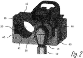
Fig. 2 is a rear perspective view of the electrical connector assembly ofFig. 1 in accordance with an embodiment of the invention; -
Fig. 3 is an exploded view of the electrical connector assembly ofFig. 1 in accordance with an embodiment of the invention; -
Fig. 4 is an isolated perspective view of a moveable member that provides a primary lock reinforcement and secondary terminal lock function that is part of the electrical connector assembly ofFig. 1 in accordance with an embodiment of the invention; -
Fig. 5 is a pre-assembly view of the electrical connector assembly ofFig. 1 in accordance with an embodiment of the invention; -
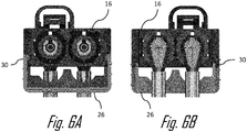
Fig. 6A is a front view of the electrical connector assembly ofFig. 1 with the moveable member in a pre-staged position in accordance with an embodiment of the invention; -
Fig. 6B is a rear view of the electrical connector assembly ofFig. 1 with the moveable member in the pre-staged position in accordance with an embodiment of the invention; -
Fig. 7A is a front view of the electrical connector assembly ofFig. 1 with the moveable member in the staged position in accordance with an embodiment of the invention; and -
Fig. 7B is a rear view of the electrical connector assembly ofFig. 1 with the moveable member in the staged position in accordance with an embodiment of the invention. - Reference will now be made in detail to embodiments, examples of which are illustrated in the accompanying drawings. In the following detailed description, numerous specific details are set forth to provide a thorough understanding of the various described embodiments. However, it will be apparent to one of ordinary skill in the art that the various described embodiments may be practiced without these specific details. In other instances, well-known methods, procedures, components, circuits, and networks have not been described in detail so as not to unnecessarily obscure aspects of the embodiments.
-
Figs. 1 through 7B illustrate an example of aconnector assembly 10, hereinafter referred to as theconnector 10. In this illustrated example, theconnector 10 is configured to interconnectwire cables 12 havingterminals 14 attached to ends of thecables 12. Theconnector 10 includes aconnector body 16 that definesseveral cavities 18 extending longitudinally through theconnector body 16. Thecavities 18 are configured to receive theterminals 14. Theconnector body 16 also includes flexibleprimary locking arms 20 that are configured to retain theterminals 14 within thecavities 18. Theseprimary locking arms 20 flex outwardly as theterminals 14 are inserted into thecavities 18 and then return to their original position once theterminals 14 are fully seated within thecavities 18. Theconnector body 16 further defines a pair of first grooves, hereinafter referred to as thelower grooves 22 and a pair of second grooves, hereinafter referred to as theupper grooves 24 in two opposite outer surfaces of theconnector body 16. Theconnector body 16 is formed of a dielectric polymer material, such as polyamide (NYLON), polybutylene terephthalate (PBT), or acrylonitrile butadiene styrene (ABS). - The
connector 10 also includes a retaining device, hereinafter referred to as theretainer 26. Theretainer 26 is also formed of a dielectric polymer material, such as NYLON, PBT, or ABS. Theretainer 26 is attached to theconnector body 16 and is moveable from apre-staged position 30 shown inFigs. 6A and 6B which allows theterminals 14 to be inserted or removed from thecavities 18 to a stagedposition 32 shown inFigs. 7A and 7B which inhibits theterminals 14 from being inserted or removed from thecavities 18. Theretainer 26 has a generally planar base portion, hereinafter referred to as thebase 34. - Pairs of complaint cantilevered
arms 36 have fixed ends that are attached to thebase 34 and extend upwardly from two opposed distal edges of thebase 34. Free ends of the arms each define latch features 28 that are configured to engage thelower grooves 22 when theretainer 26 is in thepre-staged position 30, thus securing theretainer 26 to theconnector body 16 in thepre-staged position 30. The latch features 28 that are also configured to engage theupper grooves 24 when theretainer 26 is in the stagedposition 32, thus securing theretainer 26 to theconnector body 16 in the stagedposition 32. - The
retainer 26 further includes a retainingwall 38 that extends perpendicularly upwardly from a rear edge thebase 34 and is arranged generally perpendicular to the cantileveredarms 36. The retainingwall 38 is configured to partially block rear openings of thecavities 18, thereby forming a secondary terminal locking feature by inhibiting removal of theterminals 14 from thecavities 18. The retainingwall 38 is attached toside walls 40 that are generally parallel to the cantileveredarms 36. Theseside walls 40 cooperate with the retainingwall 38 to provide theretaining wall 38 with enhanced resistance to removal of theterminals 14 when theretainer 26 in the stagedposition 32. - In the illustrated example, the upper edge of the
terminal retaining wall 38 definesconcave cutouts 42 that engagecircumferential grooves 44 in an innerterminal housing 46 conforming to FAKRA specifications in which the terminal is disposed. A radius of theconcave cutouts 42 is sized and shaped to correspond with the shape of thecircumferential grooves 44 of the innerterminal housing 46. -
Figs. 6A and 6B illustrate theconnector 10 with theretainer 26 in thepre-staged position 30. In thepre-staged position 30, the latch features 28 of the cantileveredarms 36 are engaged with thelower grooves 22 and the retainingwall 38 is not blocking thecavities 18. In thepre-staged position 30, theprimary locking arms 20 can flex andterminals 14 may be inserted through the rear openings of thecavities 18. -
Figs. 7A and 7B illustrate theconnector 10 with theretainer 26 in the stagedposition 32. In the stagedposition 32, the latch features 28 of the cantileveredarms 36 are engaged with theupper grooves 24 and theside walls 40 cover theprimary locking arms 20 and inhibit flexing of theprimary locking arms 20. The retainingwall 38 also partially blocks the rear openings of thecavities 18. In the stagedposition 32, removal of theterminals 14 from thecavities 18 is inhibited. - The
side walls 40 and theprimary locking arms 20 are arranged such that movement of theretainer 26 from thepre-staged position 30 to the stagedposition 32 is inhibited if the terminal is not properly seated within the terminal cavity. This feature provides a benefit of alerting an assembly operator that one or more of the terminals are improperly installed within thecavities 18 of theconnector body 16. - While the illustrated example of
Figs. 1-7B hasterminals 14 that are generally arranged in at right angle to thecables 12, alternative embodiments of the connector may be envisioned in which the terminals are arranged generally parallel or in line with the cables. - Although the present disclosure is not so limited, the following numbered examples demonstrate one or more aspects of the disclosure.
- Example 1 - A connector assembly, comprising: a connector body defining a plurality of cavities, extending longitudinally through the connector body; inner terminal housings and disposed within the cavities, the inner terminal housings configured to hold electrical terminals attached to electrical cables; a retaining device slidably attached to the connector body and moveable from a pre-staged position to a staged position, wherein the retaining device allows the inner terminal housings to be inserted or removed from the cavities when in the pre-staged position and inhibits the inner terminal housings from being inserted or removed from the cavities when in the staged position.
- Example 2 - The connector assembly according to example 1, wherein a connector body includes flexible primary locking arms configured to retain the inner terminal housings within the cavities.
- Example 3 - The connector assembly according to example 1 or 2, wherein the connector body further define a pair of upper grooves and a pair of lower grooves in opposite outer surfaces of the connector body.
- Example 4 - The connector assembly according to example 3, wherein the retaining device has a generally planar base portion and a pair of complaint cantilevered arms having fixed ends attached to the base and extending from two opposed distal edges of the base.
- Example 5 - The connector assembly according to example 4, wherein free ends of the arms each define latch features are configured to engage the lower grooves when the retaining device is in the pre-staged position, thus securing the retaining device to the connector body in the pre-staged position and further configured to engage the upper grooves when the retainer is in the staged
position 32, thus securing the retaining device to the connector body in the staged position. - Example 6 - The connector assembly according to example 5, wherein the retaining device further includes a terminal retaining wall that extends perpendicularly from an edge of the base and is arranged generally perpendicular to the cantilevered arms and wherein the retaining wall is configured to partially block rear openings of the cavities.
- Example 7 - The connector assembly according to example 6, wherein the retaining wall is attached to side walls that are generally parallel to the cantilevered arms.
- Example 8 - The connector assembly according to example 7, wherein the inner terminal housings define a generally cylindrical shape and wherein an upper edge of the terminal retaining wall defines concave cutouts that engage circumferential grooves in the inner terminal housings.
- Example 9 - The connector assembly according to example 8, wherein radii of the concave cutouts are sized and shaped to correspond with the shape of the circumferential grooves in the inner terminal housings.
- Example 10 - The connector assembly according to example 8 or 9, wherein the concave cutouts define a mirrored J shape.
- Example 11 - The connector assembly according to any one of the examples 7 to 10, wherein the side walls and the primary locking arms are arranged such that movement of the retainer from the pre-staged position to the staged position is inhibited when the inner terminal housings are not properly seated within the cavities.
- Example 12 - The connector assembly according to any one of the preceding examples, wherein the connector body, the retaining device, and the inner terminal housings are each formed of a dielectric polymer material.
- Example 13 - The connector assembly according to any one of the preceding examples, wherein the connector assembly conforms to United States Council for Automotive Research USCAR-18 standards.
- Example 14 - The connector assembly according to any one of the preceding examples, wherein the cavities and the inner terminal housings conform to United States Council for Automotive Research USCAR-18 standards.
- Example 15 - The connector assembly according to any one of the preceding examples, wherein the inner terminal housing conforms to FAKRA specifications.
- Example 16 - A method of assembling a connector, comprising: inserting electrical terminals connected to electrical cables within inner terminal housings; inserting the inner terminal housings within cavities defined by a connector body having a retaining device slidably attached to the connector body while the a retaining device is in a pre-staged position which allows the inner terminal housings to be inserted in the cavities, wherein the retaining device further includes a terminal retaining wall configured to partially block rear openings of the cavities; slidably moving the retaining device from the pre-staged position to a staged position which inhibits the inner terminal housings from being removed from the cavities from a pre-staged position which allows the inner terminal housings to be inserted in the cavities.
- Example 17 - The method according to example 16, further comprising: slidably moving the retaining device from the staged position to the pre-staged position; and removing the inner terminal housings from the cavities.
- Example 18 - The method according to example 16 or 17, wherein movement of the retainer from the pre-staged position to the staged position is inhibited when the inner terminal housings are not properly seated within the cavities.
- While the illustrated embodiment is directed to an electrical connector assembly, other embodiments may be envisioned that are adapted for use with other types of connector assemblies for fiber optic cables, pneumatic tubes, hydraulic tubes, or a hybrid connector assembly including two or more of the items listed above.
- While this invention has been described in terms of the preferred embodiments thereof, it is not intended to be so limited, but rather only to the extent set forth in the claims that follow. For example, the above-described embodiments (and/or aspects thereof) may be used in combination with each other. In addition, many modifications may be made to configure a particular situation or material to the teachings of the invention without departing from its scope. Dimensions, types of materials, orientations of the various components, and the number and positions of the various components described herein are intended to define parameters of certain embodiments and are by no means limiting and are merely prototypical embodiments.
- Many other embodiments and modifications within the spirit and scope of the claims will be apparent to those of skill in the art upon reviewing the above description. The scope of the invention should, therefore, be determined with reference to the following claims, along with the full scope of equivalents to which such claims are entitled.
- As used herein, 'one or more' includes a function being performed by one element, a function being performed by more than one element, e.g., in a distributed fashion, several functions being performed by one element, several functions being performed by several elements, or any combination of the above.
- It will also be understood that, although the terms first, second, etc. are, in some instances, used herein to describe various elements, these elements should not be limited by these terms. These terms are only used to distinguish one element from another. For example, a first contact could be termed a second contact, and, similarly, a second contact could be termed a first contact, without departing from the scope of the various described embodiments. The first contact and the second contact are both contacts, but they are not the same contact.
- The terminology used in the description of the various described embodiments herein is for the purpose of describing particular embodiments only and is not intended to be limiting. As used in the description of the various described embodiments and the appended claims, the singular forms "a", "an" and "the" are intended to include the plural forms as well, unless the context clearly indicates otherwise. It will also be understood that the term "and/or" as used herein refers to and encompasses all possible combinations of one or more of the associated listed items. It will be further understood that the terms "includes," "including," "comprises," and/or "comprising," when used in this specification, specify the presence of stated features, integers, steps, operations, elements, and/or components, but do not preclude the presence or addition of one or more other features, integers, steps, operations, elements, components, and/or groups thereof.
- As used herein, the term "if' is, optionally, construed to mean "when" or "upon" or "in response to determining" or "in response to detecting," depending on the context. Similarly, the phrase "if it is determined" or "if [a stated condition or event] is detected" is, optionally, construed to mean "upon determining" or "in response to determining" or "upon detecting [the stated condition or event]" or "in response to detecting [the stated condition or event]," depending on the context.
- Additionally, while terms of ordinance or orientation may be used herein these elements should not be limited by these terms. All terms of ordinance or orientation, unless stated otherwise, are used for purposes distinguishing one element from another, and do not denote any particular order, order of operations, direction or orientation unless stated otherwise.
Claims (15)
- A connector assembly (10), comprising:a connector body (16) defining a plurality of cavities (18), extending longitudinally through the connector body (16);inner terminal housings (46) and disposed within the cavities (18), the inner terminal housings (46) configured to hold electrical terminals (14) attached to electrical cables (12);a retaining device (26) slidably attached to the connector body (16) and moveable from a pre-staged position (30) to a staged position (32), wherein the retaining device (26) allows the inner terminal housings (46) to be inserted or removed from the cavities (18) when in the pre-staged position (30) and inhibits the inner terminal housings (46) from being inserted or removed from the cavities (18) when in the staged position (32).
- The connector assembly (10) according to claim 1, wherein a connector body (16) includes flexible primary locking arms (20) configured to retain the inner terminal housings (46) within the cavities (18).
- The connector assembly (10) according to claim 1 or 2, wherein the connector body (16) further define a pair of upper grooves (22) and a pair of lower grooves (24) in opposite outer surfaces of the connector body (16).
- The connector assembly (10) according to claim 3, wherein the retaining device (26) has a generally planar base portion (34) and a pair of complaint cantilevered arms (36) having fixed ends attached to the base (34) and extending from two opposed distal edges of the base (34).
- The connector assembly (10) according to claim 4, wherein free ends of the arms each define latch features (28) are configured to engage the lower grooves (22) when the retaining device (26) is in the pre-staged position (30), thus securing the retaining device (26) to the connector body (16) in the pre-staged position (30) and further configured to engage the upper grooves (24) when the retainer (26) is in the staged position 32, thus securing the retaining device (26) to the connector body (16) in the staged position (32).
- The connector assembly (10) according to claim 5, wherein the retaining device (26) further includes a terminal retaining wall (38) that extends perpendicularly from an edge of the base (34) and is arranged generally perpendicular to the cantilevered arms (36) and wherein the retaining wall (38) is configured to partially block rear openings of the cavities (18).
- The connector assembly (10) according to claim 6, wherein the retaining wall (38) is attached to side walls (40) that are generally parallel to the cantilevered arms (36).
- The connector assembly (10) according to claim 7, wherein the inner terminal housings (46) define a generally cylindrical shape and wherein an upper edge of the terminal retaining wall (38) defines concave cutouts (42) that engage circumferential grooves (44) in the inner terminal housings (46).
- The connector assembly (10) according to claim 8, wherein radii of the concave cutouts (42) are sized and shaped to correspond with the shape of the circumferential grooves (44) in the inner terminal housings (46).
- The connector assembly (10) according to claim 8 or 9, wherein the concave cutouts (42) define a mirrored J shape.
- The connector assembly (10) according to any one of the claims 7 to 10, wherein the side walls (40) and the primary locking arms (20) are arranged such that movement of the retainer (26) from the pre-staged position (30) to the staged position (32) is inhibited when the inner terminal housings (46) are not properly seated within the cavities (18).
- The connector assembly (10) according to any one of the preceding claims, wherein the connector body (16), the retaining device (26), and the inner terminal housings (46) are each formed of a dielectric polymer material.
- A method of assembling a connector, comprising:inserting electrical terminals (14) connected to electrical cables (12) within inner terminal housings (46);inserting the inner terminal housings (46) within cavities (18) defined by a connector body (16) having a retaining device (26) slidably attached to the connector body (16) while the a retaining device (26) is in a pre-staged position (30) which allows the inner terminal housings (46) to be inserted in the cavities (18), wherein the retaining device (26) further includes a terminal retaining wall (38) configured to partially block rear openings of the cavities (18);slidably moving the retaining device (26) from the pre-staged position (30) to a staged position (32) which inhibits the inner terminal housings (46) from being removed from the cavities (18) from a pre-staged position (30) which allows the inner terminal housings (46) to be inserted in the cavities (18).
- The method according to claim 13, further comprising:slidably moving the retaining device (26) from the staged position (32) to the pre-staged position (30); andremoving the inner terminal housings (46) from the cavities (18).
- The method according to claim 13 or 14, wherein movement of the retainer (26) from the pre-staged position (30) to the staged position (32) is inhibited when the inner terminal housings (46) are not properly seated within the cavities (18).
Applications Claiming Priority (1)
| Application Number | Priority Date | Filing Date | Title |
|---|---|---|---|
| US201962908678P | 2019-10-01 | 2019-10-01 |
Publications (2)
| Publication Number | Publication Date |
|---|---|
| EP3800744A1 true EP3800744A1 (en) | 2021-04-07 |
| EP3800744B1 EP3800744B1 (en) | 2024-02-28 |
Family
ID=72717778
Family Applications (1)
| Application Number | Title | Priority Date | Filing Date |
|---|---|---|---|
| EP20199638.6A Active EP3800744B1 (en) | 2019-10-01 | 2020-10-01 | Connector assembly and method of assembling |
Country Status (3)
| Country | Link |
|---|---|
| US (1) | US11515660B2 (en) |
| EP (1) | EP3800744B1 (en) |
| CN (1) | CN112599992B (en) |
Cited By (1)
| Publication number | Priority date | Publication date | Assignee | Title |
|---|---|---|---|---|
| EP4170399A1 (en) * | 2021-10-19 | 2023-04-26 | MD Elektronik GmbH | Connector |
Families Citing this family (5)
| Publication number | Priority date | Publication date | Assignee | Title |
|---|---|---|---|---|
| US20240297462A1 (en) * | 2021-06-25 | 2024-09-05 | Commscope Technologies Llc | Security connector for a single twisted pair of conductors |
| USD1040107S1 (en) * | 2021-09-27 | 2024-08-27 | Smk Corporation | Electrical connector |
| US12580329B2 (en) | 2022-11-22 | 2026-03-17 | Aptiv Technologies AG | Electrical connector assembly and method of assembling same |
| US12418131B2 (en) | 2023-05-03 | 2025-09-16 | Aptiv Technologies AG | Primary lock reinforcement for connector locking system with resilient and rigid locking surfaces |
| KR102835807B1 (en) * | 2023-12-08 | 2025-07-21 | 협진커넥터(주) | Socket part of mini fakra connector |
Citations (4)
| Publication number | Priority date | Publication date | Assignee | Title |
|---|---|---|---|---|
| US7048581B1 (en) * | 2004-10-28 | 2006-05-23 | Yazaki North America, Inc. | TPA connector for rotatable terminals |
| US20090130902A1 (en) * | 2007-11-15 | 2009-05-21 | Tyco Electronics Corporation | Multi position electrical connector assembly |
| US7762854B1 (en) * | 2009-05-19 | 2010-07-27 | F Time Technology Industrial Co., Ltd. | RF connector assembly |
| US9882317B1 (en) * | 2016-09-15 | 2018-01-30 | Te Connectivity Corporation | Connector system with hybrid electrical connectors |
Family Cites Families (29)
| Publication number | Priority date | Publication date | Assignee | Title |
|---|---|---|---|---|
| US4655525A (en) * | 1985-07-03 | 1987-04-07 | Amp Incorporated | Means for retaining terminals in a connector |
| US4984998A (en) * | 1989-12-15 | 1991-01-15 | Amp Incorporated | High density electrical connector |
| JP2003007388A (en) * | 2001-06-18 | 2003-01-10 | Sumitomo Wiring Syst Ltd | Connector |
| TW572416U (en) * | 2002-11-15 | 2004-01-11 | Hon Hai Prec Ind Co Ltd | Stacked electrical connector |
| US6827609B1 (en) * | 2003-11-12 | 2004-12-07 | Tyco Electronics Corporation | Electrical connector having improved terminal positioning assurance member |
| US7044808B1 (en) * | 2005-06-07 | 2006-05-16 | Tyco Electronics Corporation | Connector assembly with terminal position assurance device |
| JP2006344538A (en) * | 2005-06-10 | 2006-12-21 | Tyco Electronics Amp Kk | Electric connector |
| US7285011B2 (en) | 2005-10-24 | 2007-10-23 | Tyco Electronics Corporation | Cable exit for an electrical connector assembly |
| US7347745B1 (en) * | 2007-01-19 | 2008-03-25 | Tyco Electronics Corporation | Three position electrical connector assembly |
| US7625251B2 (en) * | 2007-09-25 | 2009-12-01 | Tyco Electronics Corporation | Connector with redundant terminal locking |
| US7682180B2 (en) * | 2008-04-29 | 2010-03-23 | Tyco Electronics Corporation | Electrical connector with integral terminal retention and terminal position assurance |
| US7980894B1 (en) | 2010-08-23 | 2011-07-19 | Tyco Electronics Corporation | Coaxial connector with a cable receptor with an outer contact |
| US8282415B1 (en) | 2011-04-21 | 2012-10-09 | Tyco Electronics Corporation | Multi-port connector assembly |
| US9033736B2 (en) * | 2013-05-07 | 2015-05-19 | J.S.T. Corporation | Electrical connector with maximized circuit-to-circuit isolation distance |
| US10673168B2 (en) * | 2016-01-14 | 2020-06-02 | J.S.T. Corporation | MSL connector series |
| US10622746B2 (en) * | 2016-01-15 | 2020-04-14 | J.S.T. Corporation | Terminal position assurance member and method of operating a terminal position assurance member |
| US9680256B1 (en) | 2016-03-17 | 2017-06-13 | Te Connectivity Corporation | Connector system with connector position assurance |
| US20170358875A1 (en) * | 2016-06-09 | 2017-12-14 | Tyco Electronics Corporation | Electrical contact with anti-rotation feature |
| JP6782574B2 (en) | 2016-07-22 | 2020-11-11 | 矢崎総業株式会社 | connector |
| US9960550B2 (en) * | 2016-07-25 | 2018-05-01 | Delphi Technologies, Inc. | Coaxial connector assembly |
| DE102016215123A1 (en) * | 2016-08-12 | 2018-02-15 | Te Connectivity Germany Gmbh | Connection System |
| EP3410540B1 (en) * | 2017-05-29 | 2020-02-05 | Aptiv Technologies Limited | Electrical connector |
| CN107221811B (en) * | 2017-07-03 | 2023-06-02 | 凡甲电子(苏州)有限公司 | Electric connector and electric connector combination with same |
| DE102018213920B4 (en) * | 2017-12-12 | 2022-09-29 | Lear Corporation | Method of manufacturing an electrical connector housing assembly having an integral terminal position assurance mechanism and method of manufacturing the connector |
| US10461457B1 (en) * | 2018-07-23 | 2019-10-29 | Yazaki North America, Inc. | Connector housing and terminal position assurance joint clip site |
| US11251560B2 (en) * | 2019-03-11 | 2022-02-15 | TE Connectivity Services Gmbh | Terminal position assurance member with multiple latches |
| CN111755905B (en) * | 2019-03-27 | 2022-03-25 | 住友电装株式会社 | Connector and connector device |
| US10892577B1 (en) * | 2019-07-10 | 2021-01-12 | Lear Corporation | Electric terminal connector assembly with a terminal lock |
| CN210779132U (en) | 2019-09-03 | 2020-06-16 | 东莞市鸿儒连接器有限公司 | All-in-one FAKRA connector |
-
2020
- 2020-09-09 US US17/015,584 patent/US11515660B2/en active Active
- 2020-09-29 CN CN202011049266.7A patent/CN112599992B/en active Active
- 2020-10-01 EP EP20199638.6A patent/EP3800744B1/en active Active
Patent Citations (4)
| Publication number | Priority date | Publication date | Assignee | Title |
|---|---|---|---|---|
| US7048581B1 (en) * | 2004-10-28 | 2006-05-23 | Yazaki North America, Inc. | TPA connector for rotatable terminals |
| US20090130902A1 (en) * | 2007-11-15 | 2009-05-21 | Tyco Electronics Corporation | Multi position electrical connector assembly |
| US7762854B1 (en) * | 2009-05-19 | 2010-07-27 | F Time Technology Industrial Co., Ltd. | RF connector assembly |
| US9882317B1 (en) * | 2016-09-15 | 2018-01-30 | Te Connectivity Corporation | Connector system with hybrid electrical connectors |
Cited By (2)
| Publication number | Priority date | Publication date | Assignee | Title |
|---|---|---|---|---|
| EP4170399A1 (en) * | 2021-10-19 | 2023-04-26 | MD Elektronik GmbH | Connector |
| US12334675B2 (en) | 2021-10-19 | 2025-06-17 | Md Elektronik Gmbh | Connector |
Also Published As
| Publication number | Publication date |
|---|---|
| EP3800744B1 (en) | 2024-02-28 |
| US11515660B2 (en) | 2022-11-29 |
| CN112599992A (en) | 2021-04-02 |
| US20210098930A1 (en) | 2021-04-01 |
| CN112599992B (en) | 2023-07-07 |
Similar Documents
| Publication | Publication Date | Title |
|---|---|---|
| US11515660B2 (en) | Electrical connector assembly with retaining device | |
| CN107658656B (en) | Coaxial connector assemblies | |
| EP3284142B1 (en) | Quick connect power connector system | |
| US10886668B1 (en) | Coaxial cable connector assembly | |
| US9153889B2 (en) | Electrical connector system connectable in a straight or right angle configuration | |
| EP3787125A1 (en) | Shielded electrical connector assembly and manufacturing method thereof | |
| EP3944423A1 (en) | Coaxial connector assembly | |
| JP2019503576A (en) | Right angle coaxial electrical connector and method for verifying its proper assembly | |
| CN102544915B (en) | Connector | |
| EP3709448B1 (en) | Terminal position assurance member with multiple latches | |
| WO2017015285A1 (en) | Terminal fitting | |
| EP4228100B1 (en) | Connector assembly with an unseated terminal detection feature | |
| CN112600038A (en) | Connector with a locking member | |
| US9755350B2 (en) | Connector | |
| EP2587593B1 (en) | Electrical connector assembly with integrated wire holding means | |
| EP4507138A1 (en) | Right-angled connector with terminal retention features and method of assembling thereof | |
| US11450985B2 (en) | Connector with integrated seal retainer and secondary terminal lock | |
| US10476207B2 (en) | Electrical distribution assembly | |
| US20240162650A1 (en) | Connector with a coupling element having two protuberances | |
| EP4542779A1 (en) | Connector assembly with device for adapting a terminal to a connector body and method of assembling same | |
| US12633695B2 (en) | Male and female power terminal assembly, female and male power terminals | |
| EP4459803A1 (en) | Primary lock reinforcement for connector locking system with resilient and rigid locking surfaces | |
| CN116581580A (en) | Connector assembly with dislocating terminal detection function | |
| CN118899711A (en) | Primary locking reinforcement for connector locking systems with resilient and rigid locking surfaces |
Legal Events
| Date | Code | Title | Description |
|---|---|---|---|
| PUAI | Public reference made under article 153(3) epc to a published international application that has entered the european phase |
Free format text: ORIGINAL CODE: 0009012 |
|
| STAA | Information on the status of an ep patent application or granted ep patent |
Free format text: STATUS: THE APPLICATION HAS BEEN PUBLISHED |
|
| AK | Designated contracting states |
Kind code of ref document: A1 Designated state(s): AL AT BE BG CH CY CZ DE DK EE ES FI FR GB GR HR HU IE IS IT LI LT LU LV MC MK MT NL NO PL PT RO RS SE SI SK SM TR |
|
| AX | Request for extension of the european patent |
Extension state: BA ME |
|
| STAA | Information on the status of an ep patent application or granted ep patent |
Free format text: STATUS: REQUEST FOR EXAMINATION WAS MADE |
|
| 17P | Request for examination filed |
Effective date: 20210505 |
|
| RBV | Designated contracting states (corrected) |
Designated state(s): AL AT BE BG CH CY CZ DE DK EE ES FI FR GB GR HR HU IE IS IT LI LT LU LV MC MK MT NL NO PL PT RO RS SE SI SK SM TR |
|
| STAA | Information on the status of an ep patent application or granted ep patent |
Free format text: STATUS: EXAMINATION IS IN PROGRESS |
|
| 17Q | First examination report despatched |
Effective date: 20220318 |
|
| RAP3 | Party data changed (applicant data changed or rights of an application transferred) |
Owner name: APTIV TECHNOLOGIES LIMITED |
|
| GRAP | Despatch of communication of intention to grant a patent |
Free format text: ORIGINAL CODE: EPIDOSNIGR1 |
|
| STAA | Information on the status of an ep patent application or granted ep patent |
Free format text: STATUS: GRANT OF PATENT IS INTENDED |
|
| RIC1 | Information provided on ipc code assigned before grant |
Ipc: H01R 103/00 20060101ALN20231207BHEP Ipc: H01R 13/422 20060101ALI20231207BHEP Ipc: H01R 43/20 20060101ALI20231207BHEP Ipc: H01R 13/436 20060101ALI20231207BHEP Ipc: H01R 13/426 20060101AFI20231207BHEP |
|
| RIC1 | Information provided on ipc code assigned before grant |
Ipc: H01R 103/00 20060101ALN20231214BHEP Ipc: H01R 13/422 20060101ALI20231214BHEP Ipc: H01R 43/20 20060101ALI20231214BHEP Ipc: H01R 13/436 20060101ALI20231214BHEP Ipc: H01R 13/426 20060101AFI20231214BHEP |
|
| GRAS | Grant fee paid |
Free format text: ORIGINAL CODE: EPIDOSNIGR3 |
|
| INTG | Intention to grant announced |
Effective date: 20240108 |
|
| GRAA | (expected) grant |
Free format text: ORIGINAL CODE: 0009210 |
|
| STAA | Information on the status of an ep patent application or granted ep patent |
Free format text: STATUS: THE PATENT HAS BEEN GRANTED |
|
| AK | Designated contracting states |
Kind code of ref document: B1 Designated state(s): AL AT BE BG CH CY CZ DE DK EE ES FI FR GB GR HR HU IE IS IT LI LT LU LV MC MK MT NL NO PL PT RO RS SE SI SK SM TR |
|
| P01 | Opt-out of the competence of the unified patent court (upc) registered |
Effective date: 20240123 |
|
| REG | Reference to a national code |
Ref country code: GB Ref legal event code: FG4D |
|
| REG | Reference to a national code |
Ref country code: CH Ref legal event code: EP |
|
| REG | Reference to a national code |
Ref country code: DE Ref legal event code: R096 Ref document number: 602020026328 Country of ref document: DE |
|
| REG | Reference to a national code |
Ref country code: IE Ref legal event code: FG4D |
|
| REG | Reference to a national code |
Ref country code: LT Ref legal event code: MG9D |
|
| PG25 | Lapsed in a contracting state [announced via postgrant information from national office to epo] |
Ref country code: IS Free format text: LAPSE BECAUSE OF FAILURE TO SUBMIT A TRANSLATION OF THE DESCRIPTION OR TO PAY THE FEE WITHIN THE PRESCRIBED TIME-LIMIT Effective date: 20240628 |
|
| REG | Reference to a national code |
Ref country code: NL Ref legal event code: MP Effective date: 20240228 |
|
| PG25 | Lapsed in a contracting state [announced via postgrant information from national office to epo] |
Ref country code: LT Free format text: LAPSE BECAUSE OF FAILURE TO SUBMIT A TRANSLATION OF THE DESCRIPTION OR TO PAY THE FEE WITHIN THE PRESCRIBED TIME-LIMIT Effective date: 20240228 |
|
| PG25 | Lapsed in a contracting state [announced via postgrant information from national office to epo] |
Ref country code: GR Free format text: LAPSE BECAUSE OF FAILURE TO SUBMIT A TRANSLATION OF THE DESCRIPTION OR TO PAY THE FEE WITHIN THE PRESCRIBED TIME-LIMIT Effective date: 20240529 |
|
| PG25 | Lapsed in a contracting state [announced via postgrant information from national office to epo] |
Ref country code: HR Free format text: LAPSE BECAUSE OF FAILURE TO SUBMIT A TRANSLATION OF THE DESCRIPTION OR TO PAY THE FEE WITHIN THE PRESCRIBED TIME-LIMIT Effective date: 20240228 Ref country code: RS Free format text: LAPSE BECAUSE OF FAILURE TO SUBMIT A TRANSLATION OF THE DESCRIPTION OR TO PAY THE FEE WITHIN THE PRESCRIBED TIME-LIMIT Effective date: 20240528 Ref country code: NL Free format text: LAPSE BECAUSE OF FAILURE TO SUBMIT A TRANSLATION OF THE DESCRIPTION OR TO PAY THE FEE WITHIN THE PRESCRIBED TIME-LIMIT Effective date: 20240228 |
|
| PG25 | Lapsed in a contracting state [announced via postgrant information from national office to epo] |
Ref country code: ES Free format text: LAPSE BECAUSE OF FAILURE TO SUBMIT A TRANSLATION OF THE DESCRIPTION OR TO PAY THE FEE WITHIN THE PRESCRIBED TIME-LIMIT Effective date: 20240228 |
|
| PG25 | Lapsed in a contracting state [announced via postgrant information from national office to epo] |
Ref country code: RS Free format text: LAPSE BECAUSE OF FAILURE TO SUBMIT A TRANSLATION OF THE DESCRIPTION OR TO PAY THE FEE WITHIN THE PRESCRIBED TIME-LIMIT Effective date: 20240528 Ref country code: NO Free format text: LAPSE BECAUSE OF FAILURE TO SUBMIT A TRANSLATION OF THE DESCRIPTION OR TO PAY THE FEE WITHIN THE PRESCRIBED TIME-LIMIT Effective date: 20240528 Ref country code: NL Free format text: LAPSE BECAUSE OF FAILURE TO SUBMIT A TRANSLATION OF THE DESCRIPTION OR TO PAY THE FEE WITHIN THE PRESCRIBED TIME-LIMIT Effective date: 20240228 Ref country code: LT Free format text: LAPSE BECAUSE OF FAILURE TO SUBMIT A TRANSLATION OF THE DESCRIPTION OR TO PAY THE FEE WITHIN THE PRESCRIBED TIME-LIMIT Effective date: 20240228 Ref country code: IS Free format text: LAPSE BECAUSE OF FAILURE TO SUBMIT A TRANSLATION OF THE DESCRIPTION OR TO PAY THE FEE WITHIN THE PRESCRIBED TIME-LIMIT Effective date: 20240628 Ref country code: HR Free format text: LAPSE BECAUSE OF FAILURE TO SUBMIT A TRANSLATION OF THE DESCRIPTION OR TO PAY THE FEE WITHIN THE PRESCRIBED TIME-LIMIT Effective date: 20240228 Ref country code: GR Free format text: LAPSE BECAUSE OF FAILURE TO SUBMIT A TRANSLATION OF THE DESCRIPTION OR TO PAY THE FEE WITHIN THE PRESCRIBED TIME-LIMIT Effective date: 20240529 Ref country code: FI Free format text: LAPSE BECAUSE OF FAILURE TO SUBMIT A TRANSLATION OF THE DESCRIPTION OR TO PAY THE FEE WITHIN THE PRESCRIBED TIME-LIMIT Effective date: 20240228 Ref country code: ES Free format text: LAPSE BECAUSE OF FAILURE TO SUBMIT A TRANSLATION OF THE DESCRIPTION OR TO PAY THE FEE WITHIN THE PRESCRIBED TIME-LIMIT Effective date: 20240228 Ref country code: BG Free format text: LAPSE BECAUSE OF FAILURE TO SUBMIT A TRANSLATION OF THE DESCRIPTION OR TO PAY THE FEE WITHIN THE PRESCRIBED TIME-LIMIT Effective date: 20240228 |
|
| PG25 | Lapsed in a contracting state [announced via postgrant information from national office to epo] |
Ref country code: PT Free format text: LAPSE BECAUSE OF FAILURE TO SUBMIT A TRANSLATION OF THE DESCRIPTION OR TO PAY THE FEE WITHIN THE PRESCRIBED TIME-LIMIT Effective date: 20240628 Ref country code: PL Free format text: LAPSE BECAUSE OF FAILURE TO SUBMIT A TRANSLATION OF THE DESCRIPTION OR TO PAY THE FEE WITHIN THE PRESCRIBED TIME-LIMIT Effective date: 20240228 |
|
| REG | Reference to a national code |
Ref country code: AT Ref legal event code: MK05 Ref document number: 1662121 Country of ref document: AT Kind code of ref document: T Effective date: 20240228 |
|
| PG25 | Lapsed in a contracting state [announced via postgrant information from national office to epo] |
Ref country code: SE Free format text: LAPSE BECAUSE OF FAILURE TO SUBMIT A TRANSLATION OF THE DESCRIPTION OR TO PAY THE FEE WITHIN THE PRESCRIBED TIME-LIMIT Effective date: 20240228 Ref country code: PT Free format text: LAPSE BECAUSE OF FAILURE TO SUBMIT A TRANSLATION OF THE DESCRIPTION OR TO PAY THE FEE WITHIN THE PRESCRIBED TIME-LIMIT Effective date: 20240628 Ref country code: PL Free format text: LAPSE BECAUSE OF FAILURE TO SUBMIT A TRANSLATION OF THE DESCRIPTION OR TO PAY THE FEE WITHIN THE PRESCRIBED TIME-LIMIT Effective date: 20240228 Ref country code: LV Free format text: LAPSE BECAUSE OF FAILURE TO SUBMIT A TRANSLATION OF THE DESCRIPTION OR TO PAY THE FEE WITHIN THE PRESCRIBED TIME-LIMIT Effective date: 20240228 |
|
| PG25 | Lapsed in a contracting state [announced via postgrant information from national office to epo] |
Ref country code: DK Free format text: LAPSE BECAUSE OF FAILURE TO SUBMIT A TRANSLATION OF THE DESCRIPTION OR TO PAY THE FEE WITHIN THE PRESCRIBED TIME-LIMIT Effective date: 20240228 |
|
| PG25 | Lapsed in a contracting state [announced via postgrant information from national office to epo] |
Ref country code: SM Free format text: LAPSE BECAUSE OF FAILURE TO SUBMIT A TRANSLATION OF THE DESCRIPTION OR TO PAY THE FEE WITHIN THE PRESCRIBED TIME-LIMIT Effective date: 20240228 |
|
| PG25 | Lapsed in a contracting state [announced via postgrant information from national office to epo] |
Ref country code: CZ Free format text: LAPSE BECAUSE OF FAILURE TO SUBMIT A TRANSLATION OF THE DESCRIPTION OR TO PAY THE FEE WITHIN THE PRESCRIBED TIME-LIMIT Effective date: 20240228 Ref country code: EE Free format text: LAPSE BECAUSE OF FAILURE TO SUBMIT A TRANSLATION OF THE DESCRIPTION OR TO PAY THE FEE WITHIN THE PRESCRIBED TIME-LIMIT Effective date: 20240228 |
|
| PG25 | Lapsed in a contracting state [announced via postgrant information from national office to epo] |
Ref country code: AT Free format text: LAPSE BECAUSE OF FAILURE TO SUBMIT A TRANSLATION OF THE DESCRIPTION OR TO PAY THE FEE WITHIN THE PRESCRIBED TIME-LIMIT Effective date: 20240228 |
|
| PG25 | Lapsed in a contracting state [announced via postgrant information from national office to epo] |
Ref country code: SK Free format text: LAPSE BECAUSE OF FAILURE TO SUBMIT A TRANSLATION OF THE DESCRIPTION OR TO PAY THE FEE WITHIN THE PRESCRIBED TIME-LIMIT Effective date: 20240228 |
|
| PG25 | Lapsed in a contracting state [announced via postgrant information from national office to epo] |
Ref country code: SM Free format text: LAPSE BECAUSE OF FAILURE TO SUBMIT A TRANSLATION OF THE DESCRIPTION OR TO PAY THE FEE WITHIN THE PRESCRIBED TIME-LIMIT Effective date: 20240228 Ref country code: SK Free format text: LAPSE BECAUSE OF FAILURE TO SUBMIT A TRANSLATION OF THE DESCRIPTION OR TO PAY THE FEE WITHIN THE PRESCRIBED TIME-LIMIT Effective date: 20240228 Ref country code: RO Free format text: LAPSE BECAUSE OF FAILURE TO SUBMIT A TRANSLATION OF THE DESCRIPTION OR TO PAY THE FEE WITHIN THE PRESCRIBED TIME-LIMIT Effective date: 20240228 Ref country code: EE Free format text: LAPSE BECAUSE OF FAILURE TO SUBMIT A TRANSLATION OF THE DESCRIPTION OR TO PAY THE FEE WITHIN THE PRESCRIBED TIME-LIMIT Effective date: 20240228 Ref country code: DK Free format text: LAPSE BECAUSE OF FAILURE TO SUBMIT A TRANSLATION OF THE DESCRIPTION OR TO PAY THE FEE WITHIN THE PRESCRIBED TIME-LIMIT Effective date: 20240228 Ref country code: CZ Free format text: LAPSE BECAUSE OF FAILURE TO SUBMIT A TRANSLATION OF THE DESCRIPTION OR TO PAY THE FEE WITHIN THE PRESCRIBED TIME-LIMIT Effective date: 20240228 Ref country code: AT Free format text: LAPSE BECAUSE OF FAILURE TO SUBMIT A TRANSLATION OF THE DESCRIPTION OR TO PAY THE FEE WITHIN THE PRESCRIBED TIME-LIMIT Effective date: 20240228 |
|
| REG | Reference to a national code |
Ref country code: DE Ref legal event code: R097 Ref document number: 602020026328 Country of ref document: DE |
|
| PG25 | Lapsed in a contracting state [announced via postgrant information from national office to epo] |
Ref country code: IT Free format text: LAPSE BECAUSE OF FAILURE TO SUBMIT A TRANSLATION OF THE DESCRIPTION OR TO PAY THE FEE WITHIN THE PRESCRIBED TIME-LIMIT Effective date: 20240228 |
|
| PG25 | Lapsed in a contracting state [announced via postgrant information from national office to epo] |
Ref country code: IT Free format text: LAPSE BECAUSE OF FAILURE TO SUBMIT A TRANSLATION OF THE DESCRIPTION OR TO PAY THE FEE WITHIN THE PRESCRIBED TIME-LIMIT Effective date: 20240228 |
|
| PLBE | No opposition filed within time limit |
Free format text: ORIGINAL CODE: 0009261 |
|
| STAA | Information on the status of an ep patent application or granted ep patent |
Free format text: STATUS: NO OPPOSITION FILED WITHIN TIME LIMIT |
|
| 26N | No opposition filed |
Effective date: 20241129 |
|
| PG25 | Lapsed in a contracting state [announced via postgrant information from national office to epo] |
Ref country code: SI Free format text: LAPSE BECAUSE OF FAILURE TO SUBMIT A TRANSLATION OF THE DESCRIPTION OR TO PAY THE FEE WITHIN THE PRESCRIBED TIME-LIMIT Effective date: 20240228 |
|
| REG | Reference to a national code |
Ref country code: DE Ref legal event code: R081 Ref document number: 602020026328 Country of ref document: DE Owner name: APTIV TECHNOLOGIES AG, CH Free format text: FORMER OWNER: APTIV TECHNOLOGIES LIMITED, ST. MICHAEL, BB |
|
| REG | Reference to a national code |
Ref country code: CH Ref legal event code: PL |
|
| PG25 | Lapsed in a contracting state [announced via postgrant information from national office to epo] |
Ref country code: MC Free format text: LAPSE BECAUSE OF FAILURE TO SUBMIT A TRANSLATION OF THE DESCRIPTION OR TO PAY THE FEE WITHIN THE PRESCRIBED TIME-LIMIT Effective date: 20240228 |
|
| PG25 | Lapsed in a contracting state [announced via postgrant information from national office to epo] |
Ref country code: BE Free format text: LAPSE BECAUSE OF NON-PAYMENT OF DUE FEES Effective date: 20241031 Ref country code: LU Free format text: LAPSE BECAUSE OF NON-PAYMENT OF DUE FEES Effective date: 20241001 |
|
| PG25 | Lapsed in a contracting state [announced via postgrant information from national office to epo] |
Ref country code: CH Free format text: LAPSE BECAUSE OF NON-PAYMENT OF DUE FEES Effective date: 20241031 |
|
| REG | Reference to a national code |
Ref country code: BE Ref legal event code: MM Effective date: 20241031 |
|
| PGFP | Annual fee paid to national office [announced via postgrant information from national office to epo] |
Ref country code: GB Payment date: 20250924 Year of fee payment: 6 |
|
| PGFP | Annual fee paid to national office [announced via postgrant information from national office to epo] |
Ref country code: FR Payment date: 20250910 Year of fee payment: 6 |
|
| PG25 | Lapsed in a contracting state [announced via postgrant information from national office to epo] |
Ref country code: IE Free format text: LAPSE BECAUSE OF NON-PAYMENT OF DUE FEES Effective date: 20241001 |
|
| PGFP | Annual fee paid to national office [announced via postgrant information from national office to epo] |
Ref country code: DE Payment date: 20250917 Year of fee payment: 6 |
|
| PG25 | Lapsed in a contracting state [announced via postgrant information from national office to epo] |
Ref country code: CY Free format text: LAPSE BECAUSE OF FAILURE TO SUBMIT A TRANSLATION OF THE DESCRIPTION OR TO PAY THE FEE WITHIN THE PRESCRIBED TIME-LIMIT; INVALID AB INITIO Effective date: 20201001 |
|
| PG25 | Lapsed in a contracting state [announced via postgrant information from national office to epo] |
Ref country code: HU Free format text: LAPSE BECAUSE OF FAILURE TO SUBMIT A TRANSLATION OF THE DESCRIPTION OR TO PAY THE FEE WITHIN THE PRESCRIBED TIME-LIMIT; INVALID AB INITIO Effective date: 20201001 |