EP3800740A1 - Connector - Google Patents
Connector Download PDFInfo
- Publication number
- EP3800740A1 EP3800740A1 EP20189601.6A EP20189601A EP3800740A1 EP 3800740 A1 EP3800740 A1 EP 3800740A1 EP 20189601 A EP20189601 A EP 20189601A EP 3800740 A1 EP3800740 A1 EP 3800740A1
- Authority
- EP
- European Patent Office
- Prior art keywords
- contact
- insulator
- contacts
- portions
- connector
- Prior art date
- Legal status (The legal status is an assumption and is not a legal conclusion. Google has not performed a legal analysis and makes no representation as to the accuracy of the status listed.)
- Granted
Links
Images






Classifications
-
- H—ELECTRICITY
- H01—ELECTRIC ELEMENTS
- H01R—ELECTRICALLY-CONDUCTIVE CONNECTIONS; STRUCTURAL ASSOCIATIONS OF A PLURALITY OF MUTUALLY-INSULATED ELECTRICAL CONNECTING ELEMENTS; COUPLING DEVICES; CURRENT COLLECTORS
- H01R12/00—Structural associations of a plurality of mutually-insulated electrical connecting elements, specially adapted for printed circuits, e.g. printed circuit boards [PCB], flat or ribbon cables, or like generally planar structures, e.g. terminal strips, terminal blocks; Coupling devices specially adapted for printed circuits, flat or ribbon cables, or like generally planar structures; Terminals specially adapted for contact with, or insertion into, printed circuits, flat or ribbon cables, or like generally planar structures
- H01R12/50—Fixed connections
- H01R12/59—Fixed connections for flexible printed circuits, flat or ribbon cables or like structures
- H01R12/592—Fixed connections for flexible printed circuits, flat or ribbon cables or like structures connections to contact elements
-
- H—ELECTRICITY
- H01—ELECTRIC ELEMENTS
- H01R—ELECTRICALLY-CONDUCTIVE CONNECTIONS; STRUCTURAL ASSOCIATIONS OF A PLURALITY OF MUTUALLY-INSULATED ELECTRICAL CONNECTING ELEMENTS; COUPLING DEVICES; CURRENT COLLECTORS
- H01R13/00—Details of coupling devices of the kinds covered by groups H01R12/70 or H01R24/00 - H01R33/00
- H01R13/02—Contact members
- H01R13/22—Contacts for co-operating by abutting
- H01R13/24—Contacts for co-operating by abutting resilient; resiliently-mounted
- H01R13/2407—Contacts for co-operating by abutting resilient; resiliently-mounted characterized by the resilient means
- H01R13/2414—Contacts for co-operating by abutting resilient; resiliently-mounted characterized by the resilient means conductive elastomers
-
- H—ELECTRICITY
- H01—ELECTRIC ELEMENTS
- H01R—ELECTRICALLY-CONDUCTIVE CONNECTIONS; STRUCTURAL ASSOCIATIONS OF A PLURALITY OF MUTUALLY-INSULATED ELECTRICAL CONNECTING ELEMENTS; COUPLING DEVICES; CURRENT COLLECTORS
- H01R12/00—Structural associations of a plurality of mutually-insulated electrical connecting elements, specially adapted for printed circuits, e.g. printed circuit boards [PCB], flat or ribbon cables, or like generally planar structures, e.g. terminal strips, terminal blocks; Coupling devices specially adapted for printed circuits, flat or ribbon cables, or like generally planar structures; Terminals specially adapted for contact with, or insertion into, printed circuits, flat or ribbon cables, or like generally planar structures
- H01R12/70—Coupling devices
- H01R12/77—Coupling devices for flexible printed circuits, flat or ribbon cables or like structures
- H01R12/777—Coupling parts carrying pins, blades or analogous contacts
-
- H—ELECTRICITY
- H01—ELECTRIC ELEMENTS
- H01R—ELECTRICALLY-CONDUCTIVE CONNECTIONS; STRUCTURAL ASSOCIATIONS OF A PLURALITY OF MUTUALLY-INSULATED ELECTRICAL CONNECTING ELEMENTS; COUPLING DEVICES; CURRENT COLLECTORS
- H01R12/00—Structural associations of a plurality of mutually-insulated electrical connecting elements, specially adapted for printed circuits, e.g. printed circuit boards [PCB], flat or ribbon cables, or like generally planar structures, e.g. terminal strips, terminal blocks; Coupling devices specially adapted for printed circuits, flat or ribbon cables, or like generally planar structures; Terminals specially adapted for contact with, or insertion into, printed circuits, flat or ribbon cables, or like generally planar structures
- H01R12/70—Coupling devices
- H01R12/77—Coupling devices for flexible printed circuits, flat or ribbon cables or like structures
- H01R12/778—Coupling parts carrying sockets, clips or analogous counter-contacts
-
- H—ELECTRICITY
- H01—ELECTRIC ELEMENTS
- H01R—ELECTRICALLY-CONDUCTIVE CONNECTIONS; STRUCTURAL ASSOCIATIONS OF A PLURALITY OF MUTUALLY-INSULATED ELECTRICAL CONNECTING ELEMENTS; COUPLING DEVICES; CURRENT COLLECTORS
- H01R13/00—Details of coupling devices of the kinds covered by groups H01R12/70 or H01R24/00 - H01R33/00
- H01R13/02—Contact members
-
- H—ELECTRICITY
- H01—ELECTRIC ELEMENTS
- H01R—ELECTRICALLY-CONDUCTIVE CONNECTIONS; STRUCTURAL ASSOCIATIONS OF A PLURALITY OF MUTUALLY-INSULATED ELECTRICAL CONNECTING ELEMENTS; COUPLING DEVICES; CURRENT COLLECTORS
- H01R13/00—Details of coupling devices of the kinds covered by groups H01R12/70 or H01R24/00 - H01R33/00
- H01R13/40—Securing contact members in or to a base or case; Insulating of contact members
- H01R13/405—Securing in non-demountable manner, e.g. moulding, riveting
- H01R13/41—Securing in non-demountable manner, e.g. moulding, riveting by frictional grip in grommet, panel or base
-
- H—ELECTRICITY
- H01—ELECTRIC ELEMENTS
- H01R—ELECTRICALLY-CONDUCTIVE CONNECTIONS; STRUCTURAL ASSOCIATIONS OF A PLURALITY OF MUTUALLY-INSULATED ELECTRICAL CONNECTING ELEMENTS; COUPLING DEVICES; CURRENT COLLECTORS
- H01R13/00—Details of coupling devices of the kinds covered by groups H01R12/70 or H01R24/00 - H01R33/00
- H01R13/46—Bases; Cases
- H01R13/502—Bases; Cases composed of different pieces
Definitions
- the present invention relates to a connector, and, more particularly, relates to a connector connected to a flexible conductor.
- JP 2018-129244 A discloses a connector as illustrated in FIG. 43 .
- This connector includes a contact 2 and a second insulator 3, the contact 2 and the second insulator 3 being disposed on both sides of a flexible substrate 1 across the flexible substrate 1.
- a flexible conductor 4 is exposed on a front surface of the flexible substrate 1, which faces the contact 2.
- the contact 2 has a projection accommodating portion 5 of recess shape formed so as to face the flexible conductor 4, and the second insulator 3 is provided with a projection 6 which projects toward a back surface of the flexible substrate 1.
- the flexible conductor 4 of the flexible substrate 1 inserted into the projection accommodating portion 5 of the contact 2 together with the projection 6 of the second insulator 3 contacts the inner surface of the projection accommodating portion 5 to thereby allow the contact 2 to be electrically connected to the flexible conductor 4, the flexible conductor 4 is required to be exposed on the front surface of the flexible substrate 1, which faces a side (fitting side) on which the counter connector is to be fitted. Therefore, in a case where the flexible conductor 4 is exposed on the back surface of the flexible substrate 1, which faces the second insulator 3, i.e., the opposite side from the fitting side, there is a problem that the contact 2 cannot be electrically connected to the flexible conductor 4.
- the present invention has been made to solve such problem in related art, and is to provide a connector in which a contact can be electrically connected to a flexible conductor even when a flexible substrate has the flexible conductor exposed so as to face the opposite side from the fitting side for fitting with the counter connector.
- a connector according to the present invention is a connector to be connected to a flexible conductor, the connector comprising:
- FIG. 1 and FIG. 2 illustrate a connector 11 according to Embodiment 1.
- the connector 11 is, for example, used as a garment-side connector portion with which a wearable device is to be fitted, and is mounted on a flexible substrate 21.
- the connector 11 includes a first insulator 12 disposed on a surface of the flexible substrate 21, four contacts 13, and a second insulator 14 which faces the first insulator 12 while the flexible substrate 21 is held between the second insulator 14 and the first insulator 12.
- the first insulator 12 has a first surface F1 which faces in a direction opposite to the flexible substrate 21 and a second surface F2 which faces the flexible substrate 21, a concave portion 12A is formed in the first surface F1, and the four contacts 13 each project vertically with respect to a planar bottom of the concave portion 12A within the concave portion 12A of the first insulator 12.
- the concave portion 12A of the first insulator 12 constitutes a counter connector accommodating portion in which part of a counter connector (not illustrated) is to be accommodated.
- the bottom of the concave portion 12A of the first insulator 12 extends along an XY plane, and a direction in which the respective contacts 13 project are referred to as a +Z direction.
- the flexible substrate 21 has a sheet-like substrate body 22 formed of an insulating material, and the substrate body 22 has a front surface 22A which faces in the +Z direction and a rear surface 22B which faces in a -Z direction.
- Four flexible conductors 23 are disposed so as to be exposed on the rear surface 22B of the substrate body 22.
- the four flexible conductors 23 independently correspond to the four contacts 13.
- the flexible conductor 23 can be constituted of, for example, a band-like or yarn-like conductor, made of conductive fibers and can be also formed from a conductive paste which is applied on the rear surface 22B of the substrate body 22 through printing, or the like.
- FIG. 3 illustrates an assembly view of the connector 11.
- the first insulator 12 is formed of an insulating material such as an insulating resin and includes four through-holes for contact 12B penetrating from the first surface F1 to the second surface F2 and communicating with an inside of the concave portion 12A which opens toward the +Z direction.
- the four through-holes for contact 12B independently correspond to the four contacts 13.
- annular stepped portions 12C are separately formed at peripheral portions of the through-holes for contact 12B.
- the flexible substrate 21 is disposed on the -Z direction side of the first insulator 12.
- the flexible substrate 21 has four openings 24 independently corresponding to the four contacts 13.
- the conductive portions 25 are independently formed along peripheries of the openings 24, and a pair of conductive contact portions 26 projecting to face each other in the X direction are formed within the opening 24.
- the pair of contact portions 26 can bend and are electrically connected to each other through the conductive portion 25, and the conductive portion 25 and the pair of contact portions 26 form part of the corresponding flexible conductor 23.
- the four contacts 13 are disposed on the -Z direction side of the flexible substrate 21.
- the four contacts 13 are each a plug-type contact formed of a conductive material such as a metal, and, when part of the counter connector which is not illustrated is accommodated in the concave portion 12A of the first insulator 12, the four contacts 13 are connected to corresponding contacts of the counter connector.
- the contact 13 has a projecting portion 13A extending in the Z direction, and a disc-shaped flange 13D formed at a -Z directional end portion of the projecting portion 13A.
- the projecting portion 13A includes a penetrating portion 13B which is disposed on the +Z direction side of the projecting portion 13A and which is to be inserted into the through-hole for contact 12B of the first insulator 12, and a large diameter portion 13C which is formed at the -Z directional end portion of the projecting portion 13A and which has an outer diameter larger than an outer diameter of the penetrating portion 13B, and a contact portion 13E which contacts the counter connector (not illustrated) is formed at an outer peripheral portion of the penetrating portion 13B.
- the large diameter portion 13C constitutes an extending portion which extends outside of the through-hole for contact 12B along the second surface F2 of the first insulator 12 when the penetrating portion 13B is inserted into the corresponding through-hole for contact 12B of the first insulator 12.
- the second insulator 14 is disposed on the -Z direction side of the four contacts 13.
- the second insulator 14 is a planar-shaped member formed of an insulating material such as an insulating resin.
- Each of the receiving members 15 is disposed between the first insulator 12 and the flexible substrate 21.
- Each of the receiving members 15 has a ring shape to surround the corresponding contact 13 and is provided to hold the pair of contact portions 26 of the flexible substrate 21 between the receiving member 15 and the outer peripheral surface of the large diameter portion 13C of the contact 13.
- the receiving member 15 has a size which allows the receiving member 15 to be fitted into the annular stepped portion 12C formed at the peripheral portion of the through-hole for contact 12B on the second surface F2 of the first insulator 12.
- Each of the waterproof members 16 is formed of an elastic member having a ring shape and is fitted into the outer peripheral portion of the projecting portion 13A so as to surround the projecting portion 13A of the corresponding contact 13, whereby a portion between the through-hole for contact 12B of the first insulator 12 and the contact 13 is made waterproof.
- the four through-holes for contact 12B of the first insulator 12, the four receiving members 15, the four openings 24 of the flexible substrate 21, the four waterproof members 16, and the four contacts 13 are positionally aligned with each other in the Z direction.
- Each of the through-holes for contact 12B of the first insulator 12 has an inner diameter larger than the outer diameter of the penetrating portion 13B of the contact 13 and smaller than the outer diameter of the large diameter portion 13C, and is configured so that the penetrating portion 13B of the contact 13 can be smoothly inserted.
- the four receiving members 15 are independently fitted into the four stepped portions 12C formed so as to correspond to the four through-holes for contact 12B of the first insulator 12, and the four waterproof members 16 are fitted into outer peripheral portions of the penetrating portions 13B of the four contacts 13.
- the flexible substrate 21 is disposed on the first insulator 12 such that the front surface 22A of the substrate body 22 contacts the second surface F2 of the first insulator 12 with the receiving members 15 being fitted into the stepped portions 12C in this manner.
- the four openings 24 of the flexible substrate 21 are located above the four through-holes for contact 12B of the first insulator 12.
- the penetrating portions 13B of the four contacts 13 are inserted into the four through-holes for contact 12B of the first insulator 12 through the four openings 24 of the flexible substrate 21.
- the flanges 13D of the contacts 13 are located above the conductive portions 25 of the flexible conductors 23.
- the second insulator 14 is adhered on the rear surface 22B of the substrate body 22 of the flexible substrate 21 with an adhesive.
- the first insulator 12 is also adhered to the flexible substrate 21 with an adhesive.
- the connector 11 is mounted on the flexible substrate 21.
- the connector 11 mounted on the flexible substrate 21 in this manner is illustrated in FIG. 8 .
- the flexible conductor 23 provided on the rear surface 22B of the substrate body 22 of the flexible substrate 21 is disposed along the second surface F2 of the first insulator 12, and when the penetrating portion 13B of the contact 13 is inserted into the through-hole for contact 12B of the first insulator 12, the pair of contact portions 26 which form part of the flexible conductor 23 bend in the +Z direction due to the large diameter portion 13C of the contact 13 and are held between the outer peripheral portion of the large diameter portion 13C and the inner peripheral surface of the receiving member 15. As a result, the pair of contact portions 26 contact the large diameter portion 13C of the contact 13, and the contact 13 is electrically connected to the flexible conductor 23.
- the ring-shaped waterproof members 16 fitted into the outer peripheral portions of the penetrating portions 13B of the contacts 13 are independently disposed between the penetrating portions 13B of the contacts 13 and the through-holes for contact 12B of the first insulator 12, intrusion of water from the first surface F1 side of the first insulator 12 at which the concave portion 12Ais formed to the second surface F2 side which contacts the flexible substrate 21 is prevented.
- the pair of contact portions 26 are bent in the +Z direction and held between the outer peripheral surface of the large diameter portion 13C of the corresponding contact 13 and the inner peripheral surface of the receiving member 15 in this manner, even if the flexible conductors 23 are exposed on the rear surface 22B of the substrate body 22 of the flexible substrate 21 and face in the -Z direction side opposite to the +Z direction side which is the fitting side for fitting with the counter connector (not illustrated), it is possible to electrically connect the contacts 13 to the flexible conductors 23.
- the receiving member 15 can be formed of a conductive material such as a metal or can be formed of an insulating material such as an insulating resin. If the receiving member 15 is formed of a metal material, compared to a case where the receiving member 15 is formed of a resin, a contact pressure of the contact portion 26 of the flexible conductor 23 to the large diameter portion 13C of the contact 13 is less likely to fluctuate because a creep phenomenon is less likely to occur and because a linear expansion coefficient of the receiving member 15 is close to a linear expansion coefficient of the contact 13. Accordingly, it is possible to improve reliability of electric connection.
- the receiving member 15 can be integrally formed with the first insulator 12.
- a first insulator 17 as illustrated in FIG. 9 is used.
- the first insulator 17 has annular receiving portions 17A separately formed at peripheral portions of the through-holes for contact 12B in place of the annular stepped portions 12C in the above-described first insulator 12, and the other configuration is the same as that of the first insulator 12.
- the present invention is not limited to this, and it is also possible to configure such that a single contact portion 26 is made to contact the large diameter portion 13C of the contact 13.
- FIG. 8 and FIG. 9 illustrate the contact 13 having the projecting portion 13A being hollow, it is also possible to use a solid contact 13 having the projecting portion 13A filled with a material forming the contact 13.
- FIG. 10 and FIG. 11 illustrate a connector 31 according to Embodiment 2.
- the connector 31 is used as, for example, a garment-side connector portion with which a wearable device is to be fitted in a similar manner to the connector 11 of Embodiment 1, and is mounted on the flexible substrate 21.
- the connector 31 includes a first insulator 32 disposed on a surface of the flexible substrate 21, four contacts 33 and a second insulator 34 which faces the first insulator 32 with the flexible substrate 21 being sandwiched between the second insulator 34 and the first insulator 32.
- the first insulator 32 has a first surface F1 which faces in a direction opposite to the flexible substrate 21 and a second surface F2 which faces the flexible substrate 21, a concave portion 32A is formed in the first surface F1, and the four contacts 33 each project vertically with respect to a planar bottom of the concave portion 32A within the concave portion 32A of the first insulator 32.
- the bottom of the concave portion 32A of the first insulator 32 extends along an XY plane, and a direction in which the respective contacts 33 project is referred to as a +Z direction.
- FIGS. 12 and 13 illustrate assembly views of the connector 31.
- the first insulator 32 is formed of an insulating material such as an insulating resin, and includes four through-holes for contact 32B penetrating from the first surface F1 to the second surface F2 and communicating with an inside of the concave potion 32A which opens toward the +Z direction.
- the four through-holes for contact 32B independently correspond to the four contacts 33.
- the flexible substrate 21 is disposed on the -Z direction side of the first insulator 32.
- the flexible substrate 21 is similar to the flexible substrate 21 in Embodiment 1 illustrated in FIG. 3 except a slight difference in a shape of the opening 24. That is, the four flexible conductors 23 are disposed to be exposed on the rear surface 22B of the substrate body 22 of the flexible substrate 21, and, further, the flexible substrate 21 has four openings 24.
- the conductive portions 25 are formed along peripheries of the respective openings 24, and a pair of contact portions 26 projecting to face each other in the X direction are formed within the opening 24.
- the pair of contact portions 26 can bend and are electrically connected to each other through the conductive portion 25, and the conductive portion 25 and the pair of contact portions 26 form part of the corresponding flexible conductor 23.
- the four contacts 33 are disposed on the -Z direction side of the flexible substrate 21.
- the four contacts 33 are each a plug-type contact formed of a conductive material such as a metal, and, in a case where part of the counter connector (not illustrated) is accommodated in the concave portion 32A of the first insulator 32, the four contacts 33 are connected to corresponding contacts of the counter connector.
- the contact 33 has a projecting portion 33A extending in the Z direction, and a flange 33D formed at the -Z directional end portion of the projection portion 33A and extending along an XY plane.
- the projecting portion 33A includes a penetrating portion 33B which is disposed in the +Z direction side of the projecting portion 33A and which is to be inserted into the through-hole for contact 32B of the first insulator 32, and a large diameter portion 33C which is formed at the -Z directional end portion of the projecting portion 33A and which has an outer diameter larger than an outer diameter of the penetrating portion 33B, and a contact portion 33E which contacts the counter connector (not illustrated) is formed at an outer peripheral portion of the penetrating portion 33B.
- the flange 33D includes a peripheral wall portion 33F which projects toward the +Z direction at an outer edge portion of the flange 33D, and constitutes an extending portion which extends outside of the through-hole for contact 32B along the second surface F2 of the first insulator 32 when the penetrating portion 33B is inserted into the corresponding through-hole for contact 32B of the first insulator 32.
- the second insulator 34 is disposed on the side of the -Z direction of the four contacts 33.
- the second insulator 34 is a planar-shaped member formed of an insulating material such as an insulating resin.
- waterproof members 36 and four receiving members 35 are disposed between the first insulator 32 and the flexible substrate 21.
- the waterproof members 36 are each formed of a ring-shaped elastic member and are fitted to the outer peripheral portions of the penetrating portions 33B so as to surround the penetrating portions 33B of the corresponding contacts 33, whereby a portion between the through-holes for contact 32B of the first insulator 32 and the contacts 33 is made waterproof.
- Each of the receiving members 35 has a ring shape to surround the large diameter portion 33C of the corresponding contact 33 and accommodated inside the peripheral wall portion 33F of the flange 33D, and is used to hold the pair of contact portions 26 of the flexible substrate 21 between the receiving member 35 and the inner peripheral surface of the peripheral wall portion 33F of the contact 33.
- the four through-holes for contact 32B of the first insulator 32, the four waterproof members 36, the four receiving members 35, the four openings 24 of the flexible substrate 21, the four contacts 33, and the four flange accommodating portions 34A of the second insulator 34 are positionally aligned with each other in the Z direction.
- Each of the through-holes for contact 32B of the first insulator 32 has an inner diameter which is larger than the outer diameter of the penetrating portion 33B of the contact 33 and which is smaller than the outer diameter of the large diameter portion 33C, and is configured so that the penetrating portion 33B of the contact 33 can be smoothly inserted.
- the flanges 33D of the four contacts 33 are independently accommodated in the four concave flange accommodating portions 34A of the second insulator 34.
- the flexible substrate 21 is disposed on the second insulator 34 such that the rear surface 22B of the substrate body 22 contacts a surface, facing in the +Z direction, of the second insulator 34.
- the penetrating portions 33B of the four contacts 33 penetrate through the four openings 24 of the flexible substrate 21 and project to a side of the front surface 22A of the substrate body 22.
- the four receiving members 35 are moved from the +Z direction to the -Z direction and are fitted into the four contacts 33 through the four openings 24 of the flexible substrate 21.
- the ring-shaped receiving members 35 are accommodated in insides of peripheral wall portions 33F of the flanges 33D while surrounding the large diameter portions 33C of the contacts 33 illustrated in FIG. 14 .
- the four waterproof members 36 are independently inserted into the four through-holes for contact 32B of the first insulator 32 from the -Z direction side.
- the first insulator 32 with the waterproof members 36 being inserted into the through-holes for contact 32B in this manner is aligned on the +Z direction side of the penetrating portions 33B of the contacts 33 which penetrate through the openings 24 of the flexible substrate 21 and which project in the +Z direction.
- the penetrating portions 33B of the four contacts 33 are independently inserted into the four through-holes for contact 32B of the first insulator 32.
- first insulator 32 is adhered to the flexible substrate 21, and the second insulator 34 is adhered to the flexible substrate 21, with an adhesive. In this manner, the process of mounting the connector 31 on the flexible substrate 21 is completed.
- the connector 31 mounted on the flexible substrate 21 in this manner is illustrated in FIG. 19 .
- the flexible conductor 23 formed on the rear surface 22B of the substrate body 22 of the flexible substrate 21 is disposed along the second surface F2 of the first insulator 32, and, when the ring-shaped receiving member 35 is fitted into an inside of the peripheral wall portion 33F of the flange 33D while surrounding the large diameter portion 33C of the contact 33 from the +Z direction, the pair of contact portions 26 which form part of the flexible conductor 23 bend in the -Z direction due to the receiving member 35 and is held between the inner peripheral surface of the peripheral wall portion 33F of the flange 33D and the outer peripheral surface of the receiving member 35. As a result, the pair of contact portions 26 contact the peripheral wall portion 33F of the flange 33D of the contact 13 due to the receiving member 35, and the contact 33 is electrically connected to the flexible conductor 23.
- a large diameter portion accommodating hole 32C having an inner diameter larger than an inner diameter of the through-hole for contact 32B is formed adjacent to the through-hole for contact 32B on the -Z direction side of the through-hole for contact 32B.
- the penetrating portion 33B of the contact 33 is inserted into the through-hole for contact 32B, and the large diameter portion 33C of the contact 33 is inserted into the large diameter portion accommodating hole 32C.
- the pair of contact portions 26 are bent in the -Z direction and held between the inner peripheral surface of the peripheral wall portion 33F of the flange 33D of the corresponding contact 33 and the outer peripheral surface of the receiving member 35 in this manner, even if the flexible conductors 23 face in the -Z direction opposite to the +Z direction side on which the counter connector (not illustrated) is to be fitted and are exposed on the rear surface 22B of the substrate body 22 of the flexible substrate 21, it is possible to electrically connect the contacts 33 to the flexible conductors 23.
- the receiving member 35 can be formed of a conductive material such as a metal or can be formed of an insulating material such as an insulating resin. Meanwhile, if the receiving member 35 is formed of a metal material, compared to a case where the receiving member 35 is formed of a resin, a contact pressure of the contact portion 26 of the flexible conductor 23 with respect to the peripheral wall portion 33F of the contact 33 is less likely to fluctuate because a creep phenomenon is less likely to occur and because a linear expansion coefficient of the receiving member 35 is close to a linear expansion coefficient of the contact 33. Accordingly, it is possible to improve reliability of electric connection.
- the receiving member 35 can be integrally formed with the first insulator 32.
- a first insulator 37 as illustrated in FIG. 20 is used.
- the first insulator 37 has annular receiving portions 37A which project toward the -Z direction from peripheral portions of the through-holes for contact 32B in the above-described first insulator 32, and the other configuration is the same as that of the first insulator 32.
- the flexible conductor 23 has the pair of contact portions 26 which contact the contact 33
- the present invention is not limited to this, and it is also possible to configure such that a single contact portion 26 is made to contact the peripheral wall portion 33F of the flange 33D of the contact 33.
- FIG. 19 and FIG. 20 illustrate a solid contact 33 filled with a material forming the contact 33, it is also possible to use a contact 33 having the projecting portion 33A being hollow.
- FIGS. 21 to 23 illustrate a connector 41 according to Embodiment 3.
- the connector 41 is used as, for example, a garment-side connector portion with which a wearable device is to be fitted in a similar manner to the connector 11 of Embodiment 1 and the connector 31 of Embodiment 2, and is mounted on a flexible substrate 51.
- the connector 41 includes a first insulator 42 disposed on a surface of the flexible substrate 51, a contact unit 61 having a plurality of contacts 43, and a second insulator 44 which faces the first insulator 42 across the flexible substrate 51.
- the first insulator 42 has a first surface F1 which faces in a direction opposite to the flexible substrate 51, a second surface F2 which faces the flexible substrate 51 and one through-hole for contact 42A which penetrates from the first surface F1 to the second surface F2.
- the contact unit 61 is disposed to project from the first surface F1 of the first insulator 42 through the through-hole for contact 42A of the first insulator 42.
- the first surface F1 of the first insulator 42 extends along an XY plane, and a direction in which the contact unit 61 projects is referred to as a +Z direction.
- the flexible substrate 51 has a sheet-like substrate body 52 formed of an insulating material, and the substrate body 52 has a front surface 52A which faces in the +Z direction and a rear surface 52B which faces in a -Z direction.
- a plurality of flexible conductors 53 are disposed to be exposed on the rear surface 52B of the substrate body 52.
- a plurality of flexible conductors 53 are each, for example, a band-like or yarn-like conductor formed of conductive fibers, extend in the X direction and are arranged in the Y direction in parallel to each other.
- the flexible conductors 53 can be also formed of a conductive paste which is applied on the rear surface 52B of the substrate body 52 through printing or the like.
- FIG. 24 illustrates an assembly view of the connector 41.
- the first insulator 42 is formed of an insulating material such as an insulating resin, has a rectangular frame shape and has a stepped portion 42B formed along a periphery of the first insulator 42 on the second surface F2 side.
- the flexible substrate 51 is disposed on the -Z direction side of the first insulator 42.
- the flexible substrate 51 has a rectangular opening 54, and, on the rear surface 52B of the substrate body 52, the plurality of flexible conductors 53 are disposed in parallel to each other on the +X direction side and the -X direction side of the opening 54.
- One end of each of the flexible conductors 53 extends to an inside of the opening 54 and forms a contact portion 56 which can bend.
- the contact unit 61 is disposed on the -Z direction side of the flexible substrate 51. As illustrated in FIG. 25 , in the contact unit 61, a plurality of contacts 43 are arranged in two rows and held by an insulator for contact 62. The two rows of the plurality of contacts 43 are arranged adjacent to each other in the X direction, and the contacts 43 constituting each row are arranged in the Y direction.
- Each of the contacts 43 is a plug-type contact formed of a conductive material such as a metal, is connected to the corresponding contact of the counter connector (not illustrated) and, as illustrated in FIG. 26 , has a planar shape which extends in a substantially L shape along an XZ plane, and the contact 43 forms a projecting portion as a whole.
- the contact 43 includes a penetrating portion 43A which extends in the Z direction and which is to be inserted into the through-hole for contact 42A of the first insulator 42 and an elongated portion 43C which extends in the X direction from the -Z directional end portion of the penetrating portion 43A.
- a contact portion 43B which contacts the counter connector (not illustrated) is formed at an end face in the X direction on the +Z directional end portion side of the penetrating portion 43A. Further, the elongated portion 43C has an end surface 43D in the X direction.
- the respective contacts 43 are held by the insulator for contact 62 such that the contact portions 43B and the end surfaces 43D in the X direction of the elongated portions 43C are exposed.
- the penetrating portions 43A of the plurality of contacts 43 penetrate through the through-hole for contact 42A, and the elongated portions 43C of the plurality of contacts 43 constitute an extending portion which extends outside of the through-hole for contact 42A along the second surface F2 of the first insulator 42.
- the insulator for contact 62 has at both end portions thereof in the X direction a pair of stepped portions 62A which extend along the Y direction on the +Z direction side of the elongated portions 43C of the plurality of contacts 43.
- the contact unit 61 has a shape symmetric about a YZ plane, and end surfaces 43D of the elongated portions 43C of the plurality of contacts 43 constituting one row among two rows of the contacts 43 face in the +X direction, and end surfaces 43D of elongated portions 43C of the plurality of contacts 43 constituting the other row face in the -X direction.
- the second insulator 44 is disposed on the -Z direction side of the contact unit 61.
- the second insulator 44 is a planar-shaped member formed of an insulating material such as an insulating resin.
- one receiving member 45 is disposed between the first insulator 42 and the flexible substrate 51.
- the receiving member 45 has a rectangular frame shape surrounding end surfaces 43D of the elongated portions 43C of the plurality of contacts 43 of the contact unit 61.
- the receiving member 45 has a size such that the receiving member 45 is fitted into the stepped portion 42B formed along the periphery of the first insulator 42.
- the waterproof member 46 is disposed between the flexible substrate 51 and the contact unit 61.
- the waterproof member 46 is formed of an elastic member having a rectangular frame shape, fitted on a pair of stepped portions 62A of the insulator for contact 62 so as to surround the contact unit 61, whereby a portion between the through-hole for contact 42A of the first insulator 42 and the contact unit 61 is made waterproof.
- the through-hole for contact 42A of the first insulator 42, the receiving member 45, the opening 54 of the flexible substrate 51, the waterproof member 46 and the contact unit 61 are disposed to be aligned with each other in the Z direction.
- the receiving member 45 is fitted into the stepped portion 42B of the first insulator 42, and the waterproof member 46 is fitted into the contact unit 61.
- the flexible substrate 51 is disposed on the first insulator 42 such that the front surface 52A of the substrate body 52 contacts the second surface F2 of the first insulator 42 with the receiving members 45 being fitted into the stepped portion 42B in this manner.
- the opening 54 of the flexible substrate 51 is disposed on the through-hole for contact 42A of the first insulator 42.
- the contact unit 61 is inserted into the through-hole for contact 42A of the first insulator 42 through the opening 54 of the flexible substrate 51 from the -Z direction. Further, as illustrated in FIG. 29 , the second insulator 44 located on the - Z direction side of the contact unit 61 is adhered on the rear surface 52B of the substrate body 52 of the flexible substrate 51 with an adhesive. Note that the first insulator 42 is also adhered to the flexible substrate 51 with an adhesive. In this manner, the process of mounting the connector 41 on the flexible substrate 51 is completed.
- the connector 41 mounted on the flexible substrate 51 in this manner is illustrated in FIG. 30 .
- the plurality of flexible conductors 53 formed on the rear surface 52B of the substrate body 52 of the flexible substrate 51 are disposed along the second surface F2 of the first insulator 42, and when the contact unit 61 is inserted into the through-hole for contact 42A of the first insulator 42, contact portions 56 of the plurality of flexible conductors 53 bend in the +Z direction due to the plurality of contacts 43 of the contact unit 61 and are held between the end surfaces 43D of the elongated portions 43C extending in the X direction along the second surface F2 of the first insulator 42 and the inner peripheral surface of the receiving member 45.
- the contact portions 56 of the plurality of flexible conductors 53 contact the end surfaces 43D of the elongated portions 43C of the corresponding contacts 43, whereby the plurality of contacts 43 are electrically connected to the plurality of flexible conductors 53.
- the contact portions 56 of the respective flexible conductors 53 are bent in the +Z direction and are held between the end surfaces 43D of the elongated portions 43C of the corresponding contacts 43 and the inner peripheral surface of the receiving member 45, even if the plurality of flexible conductors 53 face in the -Z direction opposite to the +Z direction side on which the counter connector (not illustrated) is to be fitted and are exposed on the rear surface 52B of the substrate body 52 of the flexible substrate 51, the plurality of contacts 43 can be electrically connected to the plurality of flexible conductors 53.
- a multicore connector 41 by electrically connecting the plurality of contacts 43 of the contact unit 61 to the plurality of flexible conductors 53 of the flexible substrate 51 using one receiving member 45, a multicore connector 41 can be realized.
- the plurality of contacts 43 of the contact unit 61 are arranged in two rows in the above-described Embodiment 3, the plurality of contacts 43 may be arranged in one row.
- the receiving member 45 can be formed of a conductive material such as a metal or can be formed of an insulating material such as an insulating resin. If the receiving member 45 is formed of a metal material, compared to a case where the receiving member 45 is formed of a resin, a contact pressure of the contact portion 56 of the flexible conductor 53 with respect to the end surface 43D of the elongated portions 43C of the contact 43 is less likely to fluctuate because a creep phenomenon is less likely to occur and because a linear expansion coefficient of the receiving member 45 is close to a linear expansion coefficient of the contact 43. Accordingly, it is possible to improve reliability of electric connection.
- the plurality of flexible conductors 53 contact one receiving member 45, at least a surface of the receiving member 45 is required to have an insulating property through, for example, insulating coating.
- the receiving member 45 can be integrally formed with the first insulator 42.
- a first insulator 47 as illustrated in FIG. 31 is used.
- the first insulator 47 has a rectangular frame shaped receiving portion 47A formed at a peripheral portion of the through-hole for contact 42A in place of the stepped portion 42B in the above-described first insulator 42, and the other configuration is the same as those of the first insulator 42.
- the plurality of contacts 43 are electrically connected to the plurality of flexible conductors 53.
- FIGS. 32 to 34 illustrate a connector 71 according to Embodiment 4.
- the connector 71 is used as, for example, a garment-side connector portion with which a wearable device is to be fitted in a similar manner to the connector 41 of Embodiment 3, and is mounted on the flexible substrate 51.
- the connector 71 includes a first insulator 72 disposed on a surface of the flexible substrate 51, a contact unit 81 having a plurality of contacts 73 and a second insulator 74 which faces the first insulator 72 across the flexible substrate 51.
- the first insulator 72 has a first surface F1 which faces in a direction opposite to the flexible substrate 51, a second surface F2 which faces the flexible substrate 51 and one through-hole for contact 72A which penetrates from the first surface F1 to the second surface F2.
- the contact unit 81 is disposed to project from the first surface F1 of the first insulator 72 through the through-hole for contact 72A of the first insulator 72.
- the first surface F1 of the first insulator 72 extends along an XY plane, and a direction in which the contact unit 81 projects is referred to as a +Z direction.
- FIGS. 35 and 36 illustrate assembly views of the connector 71.
- the first insulator 72 is formed of an insulating material such as an insulating resin and has a rectangular frame shape.
- the flexible substrate 51 is disposed on the -Z direction side of the first insulator 72, and further, the contact unit 81 is disposed on the -Z direction side of the flexible substrate 51.
- the contact unit 81 in the contact unit 81, the plurality of contacts 73 arranged in two rows and held by an insulator for contact 82.
- the two rows of the plurality of contacts 73 are arranged adjacent to each other in the X direction, and the contacts 73 constituting each row are arranged in the Y direction.
- the contacts 73 are each a plug-type contact formed of a conductive material such as a metal, are connected to corresponding contacts of the counter connector (not illustrated), and, as illustrated in FIG. 38 , have a planar shape which extends in a substantially J shape along an XZ plane.
- the contact 73 includes a penetrating portion 73A which extends in the Z direction and which is inserted into the through-hole for contact 72A of the first insulator 72, an elongated portion 73C which extends in the X direction from the -Z directional end portion of the penetrating portion 73A, and a rising portion 73D which rises in the Z direction in parallel to the penetrating portion 73A from a tip in the X direction of the elongated portion 73C.
- a contact portion 73B which contacts the counter connector (not illustrated) is formed at an end face in the X direction on the +Z directional end portion side of the penetrating portion 73A.
- the rising portion 73D has an inner surface 73E facing the penetrating portion 73A. Note that the penetrating portion 73A forms a projecting portion.
- the respective contacts 73 are held by the insulator for contact 82 such that the contact portions 73B and the rising portions 73D including the inner surfaces 73E are exposed.
- the elongated portions 73C and the rising portions 73D of the plurality of contacts 73 constitute an extending portion which extends outside of the through-hole for contact 72A along the second surface F2 of the first insulator 72 when the contact unit 81 is inserted into the through-hole for contact 72A of the first insulator 72.
- the insulator for contact 82 has at both end portions thereof in the X direction stepped portions 82A which extend along the Y direction on the +Z direction side of the elongated portions 73C of the plurality of contacts 73.
- the contact unit 81 has a shape which is symmetric about a YZ plane, and, among the contacts 73 in two rows, the inner surfaces 73E of the rising portions 73D of the contacts 73 constituting one row and the inner surfaces 73E of the rising portions 73D of the contacts 73 constituting the other row separately face the stepped portions 82A in the X direction.
- One waterproof member 76 is disposed on the stepped portions 82A of the insulator for contact 82.
- the waterproof member 76 is formed of an elastic member having a rectangular frame shape and fitted on the stepped portions 82A of the insulator for contact 82 so as to surround the contact unit 81, whereby a portion between the through-hole for contact 72A of the first insulator 72 and the contact unit 81 is made waterproof.
- the second insulator 74 is disposed on the -Z direction side of the contact unit 81.
- the second insulator 74 is formed of an insulating material such as an insulating resin and has a box shape opening in the +Z direction.
- one receiving member 75 is disposed between the first insulator 72 and the flexible substrate 51.
- the receiving member 75 has a rectangular frame shape surrounding the stepped portions 82A of the contact unit 81 and is provided to hold the contact portions 56 of the plurality of flexible conductors 53 between the receiving member 75 and the inner surfaces 73E of the rising portions 73D of the plurality of contacts 73.
- the receiving member 75 has a size such that the receiving member 75 is fitted into insides of the inner surfaces 73E of the rising portions 73D of the plurality of contacts 73 arranged in two rows in the contact unit 81.
- the through-hole for contact 72A of the first insulator 72, the receiving member 75, the opening 54 of the flexible substrate 51, the contact unit 81 and the second insulator 74 are disposed to be aligned with each other in the Z direction.
- the flexible substrate 51 is disposed on the contact unit 81 such that the rear surface 52B of the substrate body 52 contacts surfaces, facing in the +Z direction, of the rising portions 73D of the plurality of contacts 73 of the contact unit 81.
- the penetrating portions 73A of the plurality of contacts 73 of the contact unit 81 project in the +Z direction from the opening 54 of the flexible substrate 51.
- the receiving member 75 is moved toward the contact unit 81 from the +Z direction and is fitted into insides of the inner surfaces 73E of the rising portions 73D of the plurality of contacts 73 arranged in two rows of the contact unit 81.
- the first insulator 72 is disposed on the flexible substrate 51 from the +Z direction.
- the penetrating portions 73A of the plurality of contacts 73 of the contact unit 81 project on the +Z direction side through the through-hole for contact 72A of the first insulator 72.
- the second insulator 74 located on the -Z direction side of the flexible substrate 51 is adhered on the rear surface 52B of the substrate body 52 of the flexible substrate 51 with an adhesive.
- the first insulator 72 is also adhered to the flexible substrate 51 with an adhesive. In this manner, the process of mounting the connector 71 on the flexible substrate 51 is completed.
- the connector 71 mounted on the flexible substrate 51 in this manner is illustrated in FIG. 41 .
- the plurality of flexible conductors 53 formed on the rear surface 52B of the substrate body 52 of the flexible substrate 51 are disposed along the second surface F2 of the first insulator 72, and when the receiving member 75 is fitted into insides of the inner surfaces 73E of the rising portions 73D of the plurality of contacts 73, the contact portions 56 of the plurality of flexible conductors 53 bend in the -Z direction due to the receiving member 75 and are held between the inner surfaces 73E of the rising portions 73D of the plurality of contacts 73 and the outer peripheral surface of the receiving member 75.
- the contact portions 56 of the plurality of flexible conductors 53 contact the inner surfaces 73E of the rising portions 73D of the corresponding contacts 73, whereby the plurality of contacts 73 are electrically connected to the plurality of flexible conductors 53.
- the contact portions 56 of the respective flexible conductors 53 are bent in the -Z direction and held between the inner surfaces 73E of the rising portions 73D of the corresponding contacts 73 and the outer peripheral surface of the receiving member 75, even if the plurality of flexible conductors 53 face in the -Z direction opposite to the +Z direction side on which the counter connector (not illustrated) is to be fitted and are exposed on the rear surface 52B of the substrate body 52 of the flexible substrate 51, the plurality of contacts 73 can be electrically connected to the plurality of flexible conductors 53.
- Embodiment 4 by electrically connecting the plurality of contacts 73 of the contact unit 81 to the plurality of flexible conductors 53 of the flexible substrate 51 using one receiving member 75, a multicore connector 71 can be realized.
- the plurality of contacts 73 of the contact unit 81 are arranged in two rows in the above-described Embodiment 4, the plurality of contacts 73 may be arranged in one row.
- the receiving member 75 can be formed of a conductive material such as a metal or can be formed of an insulating material such as an insulating resin. If the receiving member 75 is formed of a metal material, compared to a case where the receiving member 75 is formed of a resin, a contact pressure of the contact portion 56 of the flexible conductor 53 with respect to the inner surface 73E of the rising portion 73D of the contact 73 is less likely to fluctuate because a creep phenomenon is less likely to occur and because a linear expansion coefficient of the receiving member 75 is close to a linear expansion coefficient of the contact 73. Accordingly, it is possible to improve reliability of electric connection.
- the plurality of flexible conductors 53 contact one receiving member 75, at least a surface of the receiving member 75 is required to have an insulating property through, for example, insulating coating.
- the receiving member 75 can be integrally formed with the first insulator 72.
- a first insulator 77 as illustrated in FIG. 42 is used.
- the first insulator 77 has an annular receiving portion 77A which projects toward the -Z direction from a peripheral portion of the through-hole for contact 72A in the above-described first insulator 72, and the other configuration is the same as that of the first insulator 72.
- the plurality of contacts 73 are electrically connected to the plurality of flexible conductors 53.
- the connector 11, 31, 41, 71 is mounted on the flexible substrate 21, 51 in which the flexible conductors 23, 53 are supported by the insulating substrate body 22, 52
- the present invention is not limited to this.
- the connector can be configured such that the contacts 13, 33, 43, 73 are electrically connected to the flexible conductors 23, 53 which are independently disposed along the second surface F2 of the first insulator 12, 17, 32, 37, 42, 47, 72, 77 without being supported by the insulating substrate body in a similar manner.
- the present invention is not limited to this, and the connector can be configured such that receptacle type contacts are electrically connected to the flexible conductors 23, 53 in a similar manner.
Landscapes
- Coupling Device And Connection With Printed Circuit (AREA)
- Connector Housings Or Holding Contact Members (AREA)
Abstract
Description
- The present invention relates to a connector, and, more particularly, relates to a connector connected to a flexible conductor.
- As a connector connected to a flexible conductor, for example,
JP 2018-129244 A FIG. 43 . This connector includes acontact 2 and asecond insulator 3, thecontact 2 and thesecond insulator 3 being disposed on both sides of aflexible substrate 1 across theflexible substrate 1. - A
flexible conductor 4 is exposed on a front surface of theflexible substrate 1, which faces thecontact 2. Thecontact 2 has aprojection accommodating portion 5 of recess shape formed so as to face theflexible conductor 4, and thesecond insulator 3 is provided with aprojection 6 which projects toward a back surface of theflexible substrate 1. When theprojection 6 of thesecond insulator 3 is inserted into theprojection accommodating portion 5 of thecontact 2 together with theflexible substrate 1 while theflexible substrate 1 is held between theprojection 6 and theprojection accommodating portion 5 such that theprojection 6 is covered with theflexible substrate 1, theflexible substrate 1 is pressed against an inner surface of theprojection accommodating portion 5 of thecontact 2 by theprojection 6, and the inner surface of theprojection accommodating portion 5 contacts theflexible conductor 4 exposed on the front surface of theflexible substrate 1, whereby thecontact 2 is electrically connected to theflexible conductor 4. - The
contact 2 passing through a through-hole forcontact 8 of afirst insulator 7, with which a counter connector (not illustrated) is to be fitted, and which is disposed on the front surface of theflexible substrate 1, projects from a surface of thefirst insulator 7 and is connected to a corresponding contact of the counter connector upon being fitted with the counter connector. - However, because the
flexible conductor 4 of theflexible substrate 1 inserted into theprojection accommodating portion 5 of thecontact 2 together with theprojection 6 of thesecond insulator 3 contacts the inner surface of theprojection accommodating portion 5 to thereby allow thecontact 2 to be electrically connected to theflexible conductor 4, theflexible conductor 4 is required to be exposed on the front surface of theflexible substrate 1, which faces a side (fitting side) on which the counter connector is to be fitted. Therefore, in a case where theflexible conductor 4 is exposed on the back surface of theflexible substrate 1, which faces thesecond insulator 3, i.e., the opposite side from the fitting side, there is a problem that thecontact 2 cannot be electrically connected to theflexible conductor 4. - The present invention has been made to solve such problem in related art, and is to provide a connector in which a contact can be electrically connected to a flexible conductor even when a flexible substrate has the flexible conductor exposed so as to face the opposite side from the fitting side for fitting with the counter connector.
- A connector according to the present invention is a connector to be connected to a flexible conductor, the connector comprising:
- a first insulator having a first surface and a second surface which face in opposite directions to each other and having a through-hole for contact which penetrates from the first surface to the second surface;
- a contact formed of a conductive material and held by the first insulator, the contact having a projecting portion inserted into the through-hole for contact of the first insulator; and
- a receiving member disposed on a side of the second surface of the first insulator and surrounding the projecting portion of the contact,
- wherein the flexible conductor is disposed along the second surface of the first insulator,
- the contact includes a contact portion formed at one end of the projecting portion and disposed on a side of the first surface of the first insulator to contact a counter connector, and an extending portion formed on another end of the projecting portion and disposed on the side of the second surface of the first insulator to extend outside of the through-hole for contact along the second surface, and
- a part of the flexible conductor is held between the extending portion of the contact and the receiving member to contact the extending portion, whereby the contact is electrically connected to the flexible conductor.
-
-
FIG. 1 is a perspective view of a connector according toEmbodiment 1 of the present invention, seen from obliquely above. -
FIG. 2 is a perspective view of the connector according toEmbodiment 1, seen from obliquely below. -
FIG. 3 is an assembly view of the connector according toEmbodiment 1, seen from obliquely below. -
FIG. 4 is a perspective view illustrating a contact used in the connector according toEmbodiment 1. -
FIG. 5 is an assembly view when receiving members are fitted into a first insulator. -
FIG. 6 is an assembly view when a flexible substrate is disposed on the first insulator. -
FIG. 7 is an assembly view when contacts are disposed on the flexible substrate. -
FIG. 8 is a partial cross-sectional view illustrating the connector according toEmbodiment 1. -
FIG. 9 is a partial cross-sectional view illustrating a connector according to a modified example ofEmbodiment 1. -
FIG. 10 is a perspective view of a connector according toEmbodiment 2, seen from obliquely above. -
FIG. 11 is a perspective view of the connector according toEmbodiment 2, seen from obliquely below. -
FIG. 12 is an assembly view of the connector according toEmbodiment 2, seen from obliquely above. -
FIG. 13 is an assembly view of the connector according toEmbodiment 2, seen from obliquely below. -
FIG. 14 is a perspective view illustrating a contact used in the connector according toEmbodiment 2. -
FIG. 15 is an assembly view when the contacts are disposed on a second insulator. -
FIG. 16 is an assembly view when a flexible substrate is disposed on the second insulator. -
FIG. 17 is an assembly view when receiving members are fitted into the contacts. -
FIG. 18 is an assembly view when waterproof members are fitted into the contacts. -
FIG. 19 is a partial cross-sectional view illustrating the connector according toEmbodiment 2. -
FIG. 20 is a partial cross-sectional view illustrating a connector according to a modified example ofEmbodiment 2. -
FIG. 21 is a perspective view of a connector according toEmbodiment 3, seen from obliquely above. -
FIG. 22 is a perspective view of the connector according toEmbodiment 3, seen from obliquely below. -
FIG. 23 is a front view of the connector according to Embodiment 3. -
FIG. 24 is an assembly view of the connector according toEmbodiment 3, seen from obliquely below. -
FIG. 25 is a perspective view illustrating a contact unit used in the connector according toEmbodiment 3. -
FIG. 26 is a side view illustrating a contact incorporated into the contact unit inFIG. 25 . -
FIG. 27 is an assembly view when a receiving member is fitted into a first insulator, and a waterproof member is fitted into the contact unit. -
FIG. 28 is an assembly view when a flexible substrate is disposed on the first insulator. -
FIG. 29 is an assembly view when the contact unit is disposed on the flexible substrate. -
FIG. 30 is a cross-sectional view taken along line A-AinFIG. 23 . -
FIG. 31 is a cross-sectional view illustrating a connector according to a modified example ofEmbodiment 3. -
FIG. 32 is a perspective view of a connector according toEmbodiment 4, seen from obliquely above. -
FIG. 33 is a perspective view of the connector according toEmbodiment 4, seen from obliquely below. -
FIG. 34 is a front view of the connector according to Embodiment 4. -
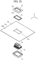
FIG. 35 is an assembly view of the connector according toEmbodiment 4, seen from obliquely above. -
FIG. 36 is an assembly view of the connector according toEmbodiment 4, seen from obliquely below. -
FIG. 37 is a perspective view illustrating a contact unit used in the connector according toEmbodiment 4. -
FIG. 38 is a side view illustrating a contact incorporated into the contact unit inFIG. 37 . -
FIG. 39 is an assembly view when a contact unit is disposed on the flexible substrate. -
FIG. 40 is an assembly view in a stage in which a first insulator and a receiving member are fitted into the contact unit. -
FIG. 41 is a cross-sectional view taken along line B-B inFIG. 34 . -
FIG. 42 is a cross-sectional view illustrating a connector according to a modified example ofEmbodiment 4. -
FIG. 43 is a cross-sectional view illustrating a contact, a projection, and a flexible substrate in a conventional connector. - Embodiments of the present invention will be described below on the basis of the accompanying drawings.
-
FIG. 1 and FIG. 2 illustrate aconnector 11 according toEmbodiment 1. Theconnector 11 is, for example, used as a garment-side connector portion with which a wearable device is to be fitted, and is mounted on aflexible substrate 21. - The
connector 11 includes afirst insulator 12 disposed on a surface of theflexible substrate 21, fourcontacts 13, and asecond insulator 14 which faces thefirst insulator 12 while theflexible substrate 21 is held between thesecond insulator 14 and thefirst insulator 12. Thefirst insulator 12 has a first surface F1 which faces in a direction opposite to theflexible substrate 21 and a second surface F2 which faces theflexible substrate 21, aconcave portion 12A is formed in the first surface F1, and the fourcontacts 13 each project vertically with respect to a planar bottom of theconcave portion 12A within theconcave portion 12A of thefirst insulator 12. Theconcave portion 12A of thefirst insulator 12 constitutes a counter connector accommodating portion in which part of a counter connector (not illustrated) is to be accommodated. - Here, for convenience sake, the bottom of the
concave portion 12A of thefirst insulator 12 extends along an XY plane, and a direction in which therespective contacts 13 project are referred to as a +Z direction. - The
flexible substrate 21 has a sheet-like substrate body 22 formed of an insulating material, and thesubstrate body 22 has afront surface 22A which faces in the +Z direction and arear surface 22B which faces in a -Z direction. Fourflexible conductors 23 are disposed so as to be exposed on therear surface 22B of thesubstrate body 22. The fourflexible conductors 23 independently correspond to the fourcontacts 13. - The
flexible conductor 23 can be constituted of, for example, a band-like or yarn-like conductor, made of conductive fibers and can be also formed from a conductive paste which is applied on therear surface 22B of thesubstrate body 22 through printing, or the like. -
FIG. 3 illustrates an assembly view of theconnector 11. Thefirst insulator 12 is formed of an insulating material such as an insulating resin and includes four through-holes forcontact 12B penetrating from the first surface F1 to the second surface F2 and communicating with an inside of theconcave portion 12A which opens toward the +Z direction. The four through-holes forcontact 12B independently correspond to the fourcontacts 13. Further, on the second surface F2 which faces in the -Z direction of thefirst insulator 12, annular steppedportions 12C are separately formed at peripheral portions of the through-holes forcontact 12B. - The
flexible substrate 21 is disposed on the -Z direction side of thefirst insulator 12. Theflexible substrate 21 has fouropenings 24 independently corresponding to the fourcontacts 13. On therear surface 22B, which faces the -Z direction, of thesubstrate body 22 of theflexible substrate 21, theconductive portions 25 are independently formed along peripheries of theopenings 24, and a pair ofconductive contact portions 26 projecting to face each other in the X direction are formed within theopening 24. The pair ofcontact portions 26 can bend and are electrically connected to each other through theconductive portion 25, and theconductive portion 25 and the pair ofcontact portions 26 form part of the correspondingflexible conductor 23. - The four
contacts 13 are disposed on the -Z direction side of theflexible substrate 21. The fourcontacts 13 are each a plug-type contact formed of a conductive material such as a metal, and, when part of the counter connector which is not illustrated is accommodated in theconcave portion 12A of thefirst insulator 12, the fourcontacts 13 are connected to corresponding contacts of the counter connector. - As illustrated in
FIG. 4 , thecontact 13 has a projectingportion 13A extending in the Z direction, and a disc-shapedflange 13D formed at a -Z directional end portion of the projectingportion 13A. The projectingportion 13A includes a penetratingportion 13B which is disposed on the +Z direction side of the projectingportion 13A and which is to be inserted into the through-hole forcontact 12B of thefirst insulator 12, and alarge diameter portion 13C which is formed at the -Z directional end portion of the projectingportion 13A and which has an outer diameter larger than an outer diameter of the penetratingportion 13B, and acontact portion 13E which contacts the counter connector (not illustrated) is formed at an outer peripheral portion of the penetratingportion 13B. Thelarge diameter portion 13C constitutes an extending portion which extends outside of the through-hole forcontact 12B along the second surface F2 of thefirst insulator 12 when the penetratingportion 13B is inserted into the corresponding through-hole forcontact 12B of thefirst insulator 12. - In addition, the
second insulator 14 is disposed on the -Z direction side of the fourcontacts 13. Thesecond insulator 14 is a planar-shaped member formed of an insulating material such as an insulating resin. - Further, four receiving
members 15 are disposed between thefirst insulator 12 and theflexible substrate 21. Each of the receivingmembers 15 has a ring shape to surround thecorresponding contact 13 and is provided to hold the pair ofcontact portions 26 of theflexible substrate 21 between the receivingmember 15 and the outer peripheral surface of thelarge diameter portion 13C of thecontact 13. - Further, the receiving
member 15 has a size which allows the receivingmember 15 to be fitted into the annular steppedportion 12C formed at the peripheral portion of the through-hole forcontact 12B on the second surface F2 of thefirst insulator 12. - Four
waterproof members 16 are disposed between theflexible substrate 21 and the fourcontacts 13. Each of thewaterproof members 16 is formed of an elastic member having a ring shape and is fitted into the outer peripheral portion of the projectingportion 13A so as to surround the projectingportion 13A of thecorresponding contact 13, whereby a portion between the through-hole forcontact 12B of thefirst insulator 12 and thecontact 13 is made waterproof. - The four through-holes for
contact 12B of thefirst insulator 12, the four receivingmembers 15, the fouropenings 24 of theflexible substrate 21, the fourwaterproof members 16, and the fourcontacts 13 are positionally aligned with each other in the Z direction. - Each of the through-holes for
contact 12B of thefirst insulator 12 has an inner diameter larger than the outer diameter of the penetratingportion 13B of thecontact 13 and smaller than the outer diameter of thelarge diameter portion 13C, and is configured so that the penetratingportion 13B of thecontact 13 can be smoothly inserted. - When the
connector 11 is mounted on theflexible substrate 21, first, as illustrated inFIG. 5 , the four receivingmembers 15 are independently fitted into the four steppedportions 12C formed so as to correspond to the four through-holes forcontact 12B of thefirst insulator 12, and the fourwaterproof members 16 are fitted into outer peripheral portions of the penetratingportions 13B of the fourcontacts 13. - The
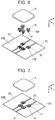
flexible substrate 21 is disposed on thefirst insulator 12 such that thefront surface 22A of thesubstrate body 22 contacts the second surface F2 of thefirst insulator 12 with the receivingmembers 15 being fitted into the steppedportions 12C in this manner. In this event, as illustrated inFIG. 6 , the fouropenings 24 of theflexible substrate 21 are located above the four through-holes forcontact 12B of thefirst insulator 12. - In this state, the penetrating
portions 13B of the fourcontacts 13 are inserted into the four through-holes forcontact 12B of thefirst insulator 12 through the fouropenings 24 of theflexible substrate 21. In this event, as illustrated inFIG. 7 , on the upper side of therear surface 22B of thesubstrate body 22 of theflexible substrate 21, theflanges 13D of thecontacts 13 are located above theconductive portions 25 of theflexible conductors 23. - Further, the
second insulator 14 is adhered on therear surface 22B of thesubstrate body 22 of theflexible substrate 21 with an adhesive. Note that thefirst insulator 12 is also adhered to theflexible substrate 21 with an adhesive. By this means, theconnector 11 is mounted on theflexible substrate 21. - The
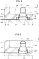
connector 11 mounted on theflexible substrate 21 in this manner is illustrated inFIG. 8 . - The
flexible conductor 23 provided on therear surface 22B of thesubstrate body 22 of theflexible substrate 21 is disposed along the second surface F2 of thefirst insulator 12, and when the penetratingportion 13B of thecontact 13 is inserted into the through-hole forcontact 12B of thefirst insulator 12, the pair ofcontact portions 26 which form part of theflexible conductor 23 bend in the +Z direction due to thelarge diameter portion 13C of thecontact 13 and are held between the outer peripheral portion of thelarge diameter portion 13C and the inner peripheral surface of the receivingmember 15. As a result, the pair ofcontact portions 26 contact thelarge diameter portion 13C of thecontact 13, and thecontact 13 is electrically connected to theflexible conductor 23. - Further, when the ring-shaped
waterproof members 16 fitted into the outer peripheral portions of the penetratingportions 13B of thecontacts 13 are independently disposed between the penetratingportions 13B of thecontacts 13 and the through-holes forcontact 12B of thefirst insulator 12, intrusion of water from the first surface F1 side of thefirst insulator 12 at which the concave portion 12Ais formed to the second surface F2 side which contacts theflexible substrate 21 is prevented. - Because the pair of
contact portions 26 are bent in the +Z direction and held between the outer peripheral surface of thelarge diameter portion 13C of thecorresponding contact 13 and the inner peripheral surface of the receivingmember 15 in this manner, even if theflexible conductors 23 are exposed on therear surface 22B of thesubstrate body 22 of theflexible substrate 21 and face in the -Z direction side opposite to the +Z direction side which is the fitting side for fitting with the counter connector (not illustrated), it is possible to electrically connect thecontacts 13 to theflexible conductors 23. - Note that the receiving
member 15 can be formed of a conductive material such as a metal or can be formed of an insulating material such as an insulating resin. If the receivingmember 15 is formed of a metal material, compared to a case where the receivingmember 15 is formed of a resin, a contact pressure of thecontact portion 26 of theflexible conductor 23 to thelarge diameter portion 13C of thecontact 13 is less likely to fluctuate because a creep phenomenon is less likely to occur and because a linear expansion coefficient of the receivingmember 15 is close to a linear expansion coefficient of thecontact 13. Accordingly, it is possible to improve reliability of electric connection. - In a case where the receiving
member 15 is formed of an insulating material, the receivingmember 15 can be integrally formed with thefirst insulator 12. In this case, for example, afirst insulator 17 as illustrated inFIG. 9 is used. Thefirst insulator 17 hasannular receiving portions 17A separately formed at peripheral portions of the through-holes forcontact 12B in place of the annular steppedportions 12C in the above-describedfirst insulator 12, and the other configuration is the same as that of thefirst insulator 12. - Since the pair of
contact portions 26 of each of theflexible conductors 23 are bent in the +Z direction and held between the outer peripheral surface of thelarge diameter portion 13C of thecorresponding contact 13 and the inner peripheral surface of the receivingportion 17A of thefirst insulator 17, thecontacts 13 are electrically connected to theflexible conductors 23. - In addition, while the
flexible conductor 23 has the pair ofcontact portions 26 which contact thecontact 13 in the above-describedEmbodiment 1, the present invention is not limited to this, and it is also possible to configure such that asingle contact portion 26 is made to contact thelarge diameter portion 13C of thecontact 13. - While
FIG. 8 and FIG. 9 illustrate thecontact 13 having the projectingportion 13A being hollow, it is also possible to use asolid contact 13 having the projectingportion 13A filled with a material forming thecontact 13. -
FIG. 10 and FIG. 11 illustrate aconnector 31 according toEmbodiment 2. Theconnector 31 is used as, for example, a garment-side connector portion with which a wearable device is to be fitted in a similar manner to theconnector 11 ofEmbodiment 1, and is mounted on theflexible substrate 21. - The
connector 31 includes afirst insulator 32 disposed on a surface of theflexible substrate 21, fourcontacts 33 and asecond insulator 34 which faces thefirst insulator 32 with theflexible substrate 21 being sandwiched between thesecond insulator 34 and thefirst insulator 32. Thefirst insulator 32 has a first surface F1 which faces in a direction opposite to theflexible substrate 21 and a second surface F2 which faces theflexible substrate 21, aconcave portion 32A is formed in the first surface F1, and the fourcontacts 33 each project vertically with respect to a planar bottom of theconcave portion 32A within theconcave portion 32A of thefirst insulator 32. - Here, for convenience sake, the bottom of the
concave portion 32A of thefirst insulator 32 extends along an XY plane, and a direction in which therespective contacts 33 project is referred to as a +Z direction. -
FIGS. 12 and13 illustrate assembly views of theconnector 31. Thefirst insulator 32 is formed of an insulating material such as an insulating resin, and includes four through-holes forcontact 32B penetrating from the first surface F1 to the second surface F2 and communicating with an inside of theconcave potion 32A which opens toward the +Z direction. The four through-holes forcontact 32B independently correspond to the fourcontacts 33. - The
flexible substrate 21 is disposed on the -Z direction side of thefirst insulator 32. Theflexible substrate 21 is similar to theflexible substrate 21 inEmbodiment 1 illustrated inFIG. 3 except a slight difference in a shape of theopening 24. That is, the fourflexible conductors 23 are disposed to be exposed on therear surface 22B of thesubstrate body 22 of theflexible substrate 21, and, further, theflexible substrate 21 has fouropenings 24. On therear surface 22B, facing in the -Z direction, of thesubstrate body 22, theconductive portions 25 are formed along peripheries of therespective openings 24, and a pair ofcontact portions 26 projecting to face each other in the X direction are formed within theopening 24. The pair ofcontact portions 26 can bend and are electrically connected to each other through theconductive portion 25, and theconductive portion 25 and the pair ofcontact portions 26 form part of the correspondingflexible conductor 23. - The four
contacts 33 are disposed on the -Z direction side of theflexible substrate 21. The fourcontacts 33 are each a plug-type contact formed of a conductive material such as a metal, and, in a case where part of the counter connector (not illustrated) is accommodated in theconcave portion 32A of thefirst insulator 32, the fourcontacts 33 are connected to corresponding contacts of the counter connector. - As illustrated in
FIG. 14 , thecontact 33 has a projectingportion 33A extending in the Z direction, and aflange 33D formed at the -Z directional end portion of theprojection portion 33A and extending along an XY plane. The projectingportion 33A includes a penetratingportion 33B which is disposed in the +Z direction side of the projectingportion 33A and which is to be inserted into the through-hole forcontact 32B of thefirst insulator 32, and alarge diameter portion 33C which is formed at the -Z directional end portion of the projectingportion 33A and which has an outer diameter larger than an outer diameter of the penetratingportion 33B, and acontact portion 33E which contacts the counter connector (not illustrated) is formed at an outer peripheral portion of the penetratingportion 33B. Further, theflange 33D includes aperipheral wall portion 33F which projects toward the +Z direction at an outer edge portion of theflange 33D, and constitutes an extending portion which extends outside of the through-hole forcontact 32B along the second surface F2 of thefirst insulator 32 when the penetratingportion 33B is inserted into the corresponding through-hole forcontact 32B of thefirst insulator 32. - Further, the
second insulator 34 is disposed on the side of the -Z direction of the fourcontacts 33. Thesecond insulator 34 is a planar-shaped member formed of an insulating material such as an insulating resin. On a surface, facing in the +Z direction, of thesecond insulator 34, provided are four concave flange accommodating portions 34Ain which flanges 33D of the fourcontacts 33 are to be independently accommodated, and fourconductor accommodating grooves 34B which are independently communicated with the fourflange accommodating portions 34A and in which the correspondingflexible conductors 23 are to be accommodated. - Further, four
waterproof members 36 and four receivingmembers 35 are disposed between thefirst insulator 32 and theflexible substrate 21. - The
waterproof members 36 are each formed of a ring-shaped elastic member and are fitted to the outer peripheral portions of the penetratingportions 33B so as to surround the penetratingportions 33B of the correspondingcontacts 33, whereby a portion between the through-holes forcontact 32B of thefirst insulator 32 and thecontacts 33 is made waterproof. - Each of the receiving
members 35 has a ring shape to surround thelarge diameter portion 33C of thecorresponding contact 33 and accommodated inside theperipheral wall portion 33F of theflange 33D, and is used to hold the pair ofcontact portions 26 of theflexible substrate 21 between the receivingmember 35 and the inner peripheral surface of theperipheral wall portion 33F of thecontact 33. - The four through-holes for
contact 32B of thefirst insulator 32, the fourwaterproof members 36, the four receivingmembers 35, the fouropenings 24 of theflexible substrate 21, the fourcontacts 33, and the fourflange accommodating portions 34A of thesecond insulator 34 are positionally aligned with each other in the Z direction. - Each of the through-holes for
contact 32B of thefirst insulator 32 has an inner diameter which is larger than the outer diameter of the penetratingportion 33B of thecontact 33 and which is smaller than the outer diameter of thelarge diameter portion 33C, and is configured so that the penetratingportion 33B of thecontact 33 can be smoothly inserted. - When the
connector 31 is mounted on theflexible substrate 21, first, as illustrated inFIG. 15 , theflanges 33D of the fourcontacts 33 are independently accommodated in the four concave flangeaccommodating portions 34A of thesecond insulator 34. - Then, the
flexible substrate 21 is disposed on thesecond insulator 34 such that therear surface 22B of thesubstrate body 22 contacts a surface, facing in the +Z direction, of thesecond insulator 34. In this event, as illustrated inFIG. 16 , the penetratingportions 33B of the fourcontacts 33 penetrate through the fouropenings 24 of theflexible substrate 21 and project to a side of thefront surface 22A of thesubstrate body 22. - Further, as illustrated in
FIG. 17 , the four receivingmembers 35 are moved from the +Z direction to the -Z direction and are fitted into the fourcontacts 33 through the fouropenings 24 of theflexible substrate 21. In more detail, the ring-shaped receivingmembers 35 are accommodated in insides ofperipheral wall portions 33F of theflanges 33D while surrounding thelarge diameter portions 33C of thecontacts 33 illustrated inFIG. 14 . - Then, the four
waterproof members 36 are independently inserted into the four through-holes forcontact 32B of thefirst insulator 32 from the -Z direction side. As illustrated inFIG. 18 , thefirst insulator 32 with thewaterproof members 36 being inserted into the through-holes forcontact 32B in this manner is aligned on the +Z direction side of the penetratingportions 33B of thecontacts 33 which penetrate through theopenings 24 of theflexible substrate 21 and which project in the +Z direction. - In this state, the penetrating
portions 33B of the fourcontacts 33 are independently inserted into the four through-holes forcontact 32B of thefirst insulator 32. - Note that the
first insulator 32 is adhered to theflexible substrate 21, and thesecond insulator 34 is adhered to theflexible substrate 21, with an adhesive. In this manner, the process of mounting theconnector 31 on theflexible substrate 21 is completed. - The
connector 31 mounted on theflexible substrate 21 in this manner is illustrated inFIG. 19 . Theflexible conductor 23 formed on therear surface 22B of thesubstrate body 22 of theflexible substrate 21 is disposed along the second surface F2 of thefirst insulator 32, and, when the ring-shaped receivingmember 35 is fitted into an inside of theperipheral wall portion 33F of theflange 33D while surrounding thelarge diameter portion 33C of thecontact 33 from the +Z direction, the pair ofcontact portions 26 which form part of theflexible conductor 23 bend in the -Z direction due to the receivingmember 35 and is held between the inner peripheral surface of theperipheral wall portion 33F of theflange 33D and the outer peripheral surface of the receivingmember 35. As a result, the pair ofcontact portions 26 contact theperipheral wall portion 33F of theflange 33D of thecontact 13 due to the receivingmember 35, and thecontact 33 is electrically connected to theflexible conductor 23. - Further, as illustrated in
FIG. 19 , in thefirst insulator 32, a large diameterportion accommodating hole 32C having an inner diameter larger than an inner diameter of the through-hole forcontact 32B is formed adjacent to the through-hole forcontact 32B on the -Z direction side of the through-hole forcontact 32B. The penetratingportion 33B of thecontact 33 is inserted into the through-hole forcontact 32B, and thelarge diameter portion 33C of thecontact 33 is inserted into the large diameterportion accommodating hole 32C. Further, when the ring-shapedwaterproof members 36 fitted into the penetratingportions 33B of thecontacts 33 are disposed between the penetratingportions 33B of thecontacts 33 and the large diameterportion accommodating hole 32C of thefirst insulator 32, intrusion of water from the first surface F1 side of thefirst insulator 32 at which theconcave portion 32A is formed to the second surface F2 side which contacts theflexible substrate 21 is prevented. - Because the pair of
contact portions 26 are bent in the -Z direction and held between the inner peripheral surface of theperipheral wall portion 33F of theflange 33D of thecorresponding contact 33 and the outer peripheral surface of the receivingmember 35 in this manner, even if theflexible conductors 23 face in the -Z direction opposite to the +Z direction side on which the counter connector (not illustrated) is to be fitted and are exposed on therear surface 22B of thesubstrate body 22 of theflexible substrate 21, it is possible to electrically connect thecontacts 33 to theflexible conductors 23. - Note that the receiving
member 35 can be formed of a conductive material such as a metal or can be formed of an insulating material such as an insulating resin. Meanwhile, if the receivingmember 35 is formed of a metal material, compared to a case where the receivingmember 35 is formed of a resin, a contact pressure of thecontact portion 26 of theflexible conductor 23 with respect to theperipheral wall portion 33F of thecontact 33 is less likely to fluctuate because a creep phenomenon is less likely to occur and because a linear expansion coefficient of the receivingmember 35 is close to a linear expansion coefficient of thecontact 33. Accordingly, it is possible to improve reliability of electric connection. - In a case where the receiving
member 35 is formed of an insulating material, the receivingmember 35 can be integrally formed with thefirst insulator 32. In this case, for example, afirst insulator 37 as illustrated inFIG. 20 is used. Thefirst insulator 37 hasannular receiving portions 37A which project toward the -Z direction from peripheral portions of the through-holes forcontact 32B in the above-describedfirst insulator 32, and the other configuration is the same as that of thefirst insulator 32. - When the pair of
contact portions 26 of each of theflexible conductors 23 are bent in the -Z direction and held between the inner peripheral surface of theperipheral wall portion 33F of theflange 33D of thecorresponding contact 33 and the outer peripheral surface of the corresponding receivingportion 37A of thefirst insulator 37, thecontacts 33 are electrically connected to theflexible conductors 23. - Further, while, in the above-described
Embodiment 2, theflexible conductor 23 has the pair ofcontact portions 26 which contact thecontact 33, the present invention is not limited to this, and it is also possible to configure such that asingle contact portion 26 is made to contact theperipheral wall portion 33F of theflange 33D of thecontact 33. - While
FIG. 19 and FIG. 20 illustrate asolid contact 33 filled with a material forming thecontact 33, it is also possible to use acontact 33 having the projectingportion 33A being hollow. -
FIGS. 21 to 23 illustrate aconnector 41 according toEmbodiment 3. Theconnector 41 is used as, for example, a garment-side connector portion with which a wearable device is to be fitted in a similar manner to theconnector 11 ofEmbodiment 1 and theconnector 31 ofEmbodiment 2, and is mounted on aflexible substrate 51. - The
connector 41 includes afirst insulator 42 disposed on a surface of theflexible substrate 51, acontact unit 61 having a plurality ofcontacts 43, and asecond insulator 44 which faces thefirst insulator 42 across theflexible substrate 51. Thefirst insulator 42 has a first surface F1 which faces in a direction opposite to theflexible substrate 51, a second surface F2 which faces theflexible substrate 51 and one through-hole forcontact 42A which penetrates from the first surface F1 to the second surface F2. Thecontact unit 61 is disposed to project from the first surface F1 of thefirst insulator 42 through the through-hole forcontact 42A of thefirst insulator 42. - Here, for convenience sake, the first surface F1 of the
first insulator 42 extends along an XY plane, and a direction in which thecontact unit 61 projects is referred to as a +Z direction. - The
flexible substrate 51 has a sheet-like substrate body 52 formed of an insulating material, and thesubstrate body 52 has afront surface 52A which faces in the +Z direction and arear surface 52B which faces in a -Z direction. A plurality offlexible conductors 53 are disposed to be exposed on therear surface 52B of thesubstrate body 52. A plurality offlexible conductors 53 are each, for example, a band-like or yarn-like conductor formed of conductive fibers, extend in the X direction and are arranged in the Y direction in parallel to each other. - Further, the
flexible conductors 53 can be also formed of a conductive paste which is applied on therear surface 52B of thesubstrate body 52 through printing or the like. -
FIG. 24 illustrates an assembly view of theconnector 41. Thefirst insulator 42 is formed of an insulating material such as an insulating resin, has a rectangular frame shape and has a steppedportion 42B formed along a periphery of thefirst insulator 42 on the second surface F2 side. - The
flexible substrate 51 is disposed on the -Z direction side of thefirst insulator 42. Theflexible substrate 51 has arectangular opening 54, and, on therear surface 52B of thesubstrate body 52, the plurality offlexible conductors 53 are disposed in parallel to each other on the +X direction side and the -X direction side of theopening 54. One end of each of theflexible conductors 53 extends to an inside of theopening 54 and forms acontact portion 56 which can bend. - The
contact unit 61 is disposed on the -Z direction side of theflexible substrate 51. As illustrated inFIG. 25 , in thecontact unit 61, a plurality ofcontacts 43 are arranged in two rows and held by an insulator forcontact 62. The two rows of the plurality ofcontacts 43 are arranged adjacent to each other in the X direction, and thecontacts 43 constituting each row are arranged in the Y direction. - Each of the
contacts 43 is a plug-type contact formed of a conductive material such as a metal, is connected to the corresponding contact of the counter connector (not illustrated) and, as illustrated inFIG. 26 , has a planar shape which extends in a substantially L shape along an XZ plane, and thecontact 43 forms a projecting portion as a whole. In more detail, thecontact 43 includes a penetratingportion 43A which extends in the Z direction and which is to be inserted into the through-hole forcontact 42A of thefirst insulator 42 and anelongated portion 43C which extends in the X direction from the -Z directional end portion of the penetratingportion 43A. Acontact portion 43B which contacts the counter connector (not illustrated) is formed at an end face in the X direction on the +Z directional end portion side of the penetratingportion 43A. Further, theelongated portion 43C has anend surface 43D in the X direction. - As illustrated in
FIG. 25 , therespective contacts 43 are held by the insulator forcontact 62 such that thecontact portions 43B and the end surfaces 43D in the X direction of theelongated portions 43C are exposed. - When the
contact unit 61 is inserted into the through-hole forcontact 42A of thefirst insulator 42, the penetratingportions 43A of the plurality ofcontacts 43 penetrate through the through-hole forcontact 42A, and theelongated portions 43C of the plurality ofcontacts 43 constitute an extending portion which extends outside of the through-hole forcontact 42A along the second surface F2 of thefirst insulator 42. - The insulator for
contact 62 has at both end portions thereof in the X direction a pair of steppedportions 62A which extend along the Y direction on the +Z direction side of theelongated portions 43C of the plurality ofcontacts 43. - Further, the
contact unit 61 has a shape symmetric about a YZ plane, andend surfaces 43D of theelongated portions 43C of the plurality ofcontacts 43 constituting one row among two rows of thecontacts 43 face in the +X direction, andend surfaces 43D ofelongated portions 43C of the plurality ofcontacts 43 constituting the other row face in the -X direction. - In
FIG. 24 , thesecond insulator 44 is disposed on the -Z direction side of thecontact unit 61. Thesecond insulator 44 is a planar-shaped member formed of an insulating material such as an insulating resin. - Further, one receiving
member 45 is disposed between thefirst insulator 42 and theflexible substrate 51. The receivingmember 45 has a rectangular frame shape surroundingend surfaces 43D of theelongated portions 43C of the plurality ofcontacts 43 of thecontact unit 61. - Further, the receiving
member 45 has a size such that the receivingmember 45 is fitted into the steppedportion 42B formed along the periphery of thefirst insulator 42. - One
waterproof member 46 is disposed between theflexible substrate 51 and thecontact unit 61. Thewaterproof member 46 is formed of an elastic member having a rectangular frame shape, fitted on a pair of steppedportions 62A of the insulator forcontact 62 so as to surround thecontact unit 61, whereby a portion between the through-hole forcontact 42A of thefirst insulator 42 and thecontact unit 61 is made waterproof. - The through-hole for
contact 42A of thefirst insulator 42, the receivingmember 45, theopening 54 of theflexible substrate 51, thewaterproof member 46 and thecontact unit 61 are disposed to be aligned with each other in the Z direction. - When the
connector 41 is mounted on theflexible substrate 51, first, as illustrated inFIG. 27 , the receivingmember 45 is fitted into the steppedportion 42B of thefirst insulator 42, and thewaterproof member 46 is fitted into thecontact unit 61. - The
flexible substrate 51 is disposed on thefirst insulator 42 such that thefront surface 52A of thesubstrate body 52 contacts the second surface F2 of thefirst insulator 42 with the receivingmembers 45 being fitted into the steppedportion 42B in this manner. In this event, as illustrated inFIG. 28 , theopening 54 of theflexible substrate 51 is disposed on the through-hole forcontact 42A of thefirst insulator 42. - In this state, the
contact unit 61 is inserted into the through-hole forcontact 42A of thefirst insulator 42 through theopening 54 of theflexible substrate 51 from the -Z direction. Further, as illustrated inFIG. 29 , thesecond insulator 44 located on the - Z direction side of thecontact unit 61 is adhered on therear surface 52B of thesubstrate body 52 of theflexible substrate 51 with an adhesive. Note that thefirst insulator 42 is also adhered to theflexible substrate 51 with an adhesive. In this manner, the process of mounting theconnector 41 on theflexible substrate 51 is completed. - The
connector 41 mounted on theflexible substrate 51 in this manner is illustrated inFIG. 30 . The plurality offlexible conductors 53 formed on therear surface 52B of thesubstrate body 52 of theflexible substrate 51 are disposed along the second surface F2 of thefirst insulator 42, and when thecontact unit 61 is inserted into the through-hole forcontact 42A of thefirst insulator 42,contact portions 56 of the plurality offlexible conductors 53 bend in the +Z direction due to the plurality ofcontacts 43 of thecontact unit 61 and are held between the end surfaces 43D of theelongated portions 43C extending in the X direction along the second surface F2 of thefirst insulator 42 and the inner peripheral surface of the receivingmember 45. As a result, thecontact portions 56 of the plurality offlexible conductors 53 contact the end surfaces 43D of theelongated portions 43C of the correspondingcontacts 43, whereby the plurality ofcontacts 43 are electrically connected to the plurality offlexible conductors 53. - Further, when the
waterproof member 46 fitted into the outer peripheral portion of thecontact unit 61 is disposed between thecontact unit 61 and the through-hole forcontact 42A of thefirst insulator 42, intrusion of water from the first surface F1 side of thefirst insulator 42 to the second surface F2 side is prevented. - In this manner, because the
contact portions 56 of the respectiveflexible conductors 53 are bent in the +Z direction and are held between the end surfaces 43D of theelongated portions 43C of the correspondingcontacts 43 and the inner peripheral surface of the receivingmember 45, even if the plurality offlexible conductors 53 face in the -Z direction opposite to the +Z direction side on which the counter connector (not illustrated) is to be fitted and are exposed on therear surface 52B of thesubstrate body 52 of theflexible substrate 51, the plurality ofcontacts 43 can be electrically connected to the plurality offlexible conductors 53. - According to
Embodiment 3, by electrically connecting the plurality ofcontacts 43 of thecontact unit 61 to the plurality offlexible conductors 53 of theflexible substrate 51 using one receivingmember 45, amulticore connector 41 can be realized. - Note that, while the plurality of
contacts 43 of thecontact unit 61 are arranged in two rows in the above-describedEmbodiment 3, the plurality ofcontacts 43 may be arranged in one row. - Note that the receiving
member 45 can be formed of a conductive material such as a metal or can be formed of an insulating material such as an insulating resin. If the receivingmember 45 is formed of a metal material, compared to a case where the receivingmember 45 is formed of a resin, a contact pressure of thecontact portion 56 of theflexible conductor 53 with respect to theend surface 43D of theelongated portions 43C of thecontact 43 is less likely to fluctuate because a creep phenomenon is less likely to occur and because a linear expansion coefficient of the receivingmember 45 is close to a linear expansion coefficient of thecontact 43. Accordingly, it is possible to improve reliability of electric connection. - In the meantime, since the plurality of
flexible conductors 53 contact one receivingmember 45, at least a surface of the receivingmember 45 is required to have an insulating property through, for example, insulating coating. - In a case where the receiving
member 45 is formed of an insulating material, the receivingmember 45 can be integrally formed with thefirst insulator 42. In this case, for example, afirst insulator 47 as illustrated inFIG. 31 is used. Thefirst insulator 47 has a rectangular frame shaped receivingportion 47A formed at a peripheral portion of the through-hole forcontact 42A in place of the steppedportion 42B in the above-describedfirst insulator 42, and the other configuration is the same as those of thefirst insulator 42. - When the
contact portions 56 of the respectiveflexible conductors 53 are bent in the +Z direction and held between the end surfaces 43D of theelongated portions 43C of the correspondingcontacts 43 and the inner peripheral surface of the receivingportion 47A of thefirst insulator 47, the plurality ofcontacts 43 are electrically connected to the plurality offlexible conductors 53. -
FIGS. 32 to 34 illustrate aconnector 71 according toEmbodiment 4. Theconnector 71 is used as, for example, a garment-side connector portion with which a wearable device is to be fitted in a similar manner to theconnector 41 ofEmbodiment 3, and is mounted on theflexible substrate 51. - The
connector 71 includes afirst insulator 72 disposed on a surface of theflexible substrate 51, acontact unit 81 having a plurality ofcontacts 73 and asecond insulator 74 which faces thefirst insulator 72 across theflexible substrate 51. Thefirst insulator 72 has a first surface F1 which faces in a direction opposite to theflexible substrate 51, a second surface F2 which faces theflexible substrate 51 and one through-hole forcontact 72A which penetrates from the first surface F1 to the second surface F2. Thecontact unit 81 is disposed to project from the first surface F1 of thefirst insulator 72 through the through-hole forcontact 72A of thefirst insulator 72. - Here, for convenience sake, the first surface F1 of the
first insulator 72 extends along an XY plane, and a direction in which thecontact unit 81 projects is referred to as a +Z direction. -
FIGS. 35 and36 illustrate assembly views of theconnector 71. Thefirst insulator 72 is formed of an insulating material such as an insulating resin and has a rectangular frame shape. - The
flexible substrate 51 is disposed on the -Z direction side of thefirst insulator 72, and further, thecontact unit 81 is disposed on the -Z direction side of theflexible substrate 51. As illustrated inFIG. 37 , in thecontact unit 81, the plurality ofcontacts 73 arranged in two rows and held by an insulator forcontact 82. The two rows of the plurality ofcontacts 73 are arranged adjacent to each other in the X direction, and thecontacts 73 constituting each row are arranged in the Y direction. - The
contacts 73 are each a plug-type contact formed of a conductive material such as a metal, are connected to corresponding contacts of the counter connector (not illustrated), and, as illustrated inFIG. 38 , have a planar shape which extends in a substantially J shape along an XZ plane. In more detail, thecontact 73 includes a penetratingportion 73A which extends in the Z direction and which is inserted into the through-hole forcontact 72A of thefirst insulator 72, anelongated portion 73C which extends in the X direction from the -Z directional end portion of the penetratingportion 73A, and a risingportion 73D which rises in the Z direction in parallel to the penetratingportion 73A from a tip in the X direction of theelongated portion 73C. Acontact portion 73B which contacts the counter connector (not illustrated) is formed at an end face in the X direction on the +Z directional end portion side of the penetratingportion 73A. Further, the risingportion 73D has aninner surface 73E facing the penetratingportion 73A. Note that the penetratingportion 73A forms a projecting portion. - As illustrated in
FIG. 37 , therespective contacts 73 are held by the insulator forcontact 82 such that thecontact portions 73B and the risingportions 73D including theinner surfaces 73E are exposed. - The
elongated portions 73C and the risingportions 73D of the plurality ofcontacts 73 constitute an extending portion which extends outside of the through-hole forcontact 72A along the second surface F2 of thefirst insulator 72 when thecontact unit 81 is inserted into the through-hole forcontact 72A of thefirst insulator 72. - The insulator for
contact 82 has at both end portions thereof in the X direction steppedportions 82A which extend along the Y direction on the +Z direction side of theelongated portions 73C of the plurality ofcontacts 73. - Further, the
contact unit 81 has a shape which is symmetric about a YZ plane, and, among thecontacts 73 in two rows, theinner surfaces 73E of the risingportions 73D of thecontacts 73 constituting one row and theinner surfaces 73E of the risingportions 73D of thecontacts 73 constituting the other row separately face the steppedportions 82A in the X direction. - One
waterproof member 76 is disposed on the steppedportions 82A of the insulator forcontact 82. Thewaterproof member 76 is formed of an elastic member having a rectangular frame shape and fitted on the steppedportions 82A of the insulator forcontact 82 so as to surround thecontact unit 81, whereby a portion between the through-hole forcontact 72A of thefirst insulator 72 and thecontact unit 81 is made waterproof. - In
FIG. 35 andFIG. 36 , thesecond insulator 74 is disposed on the -Z direction side of thecontact unit 81. Thesecond insulator 74 is formed of an insulating material such as an insulating resin and has a box shape opening in the +Z direction. - Further, one receiving
member 75 is disposed between thefirst insulator 72 and theflexible substrate 51. The receivingmember 75 has a rectangular frame shape surrounding the steppedportions 82A of thecontact unit 81 and is provided to hold thecontact portions 56 of the plurality offlexible conductors 53 between the receivingmember 75 and theinner surfaces 73E of the risingportions 73D of the plurality ofcontacts 73. - Further, the receiving
member 75 has a size such that the receivingmember 75 is fitted into insides of theinner surfaces 73E of the risingportions 73D of the plurality ofcontacts 73 arranged in two rows in thecontact unit 81. - The through-hole for
contact 72A of thefirst insulator 72, the receivingmember 75, theopening 54 of theflexible substrate 51, thecontact unit 81 and thesecond insulator 74 are disposed to be aligned with each other in the Z direction. - When the
connector 71 is mounted on theflexible substrate 51, first, theflexible substrate 51 is disposed on thecontact unit 81 such that therear surface 52B of thesubstrate body 52 contacts surfaces, facing in the +Z direction, of the risingportions 73D of the plurality ofcontacts 73 of thecontact unit 81. In this event, as illustrated inFIG. 39 , the penetratingportions 73A of the plurality ofcontacts 73 of thecontact unit 81 project in the +Z direction from theopening 54 of theflexible substrate 51. - Then, the receiving
member 75 is moved toward thecontact unit 81 from the +Z direction and is fitted into insides of theinner surfaces 73E of the risingportions 73D of the plurality ofcontacts 73 arranged in two rows of thecontact unit 81. Thereafter, thefirst insulator 72 is disposed on theflexible substrate 51 from the +Z direction. In this event, as illustrated inFIG. 40 , the penetratingportions 73A of the plurality ofcontacts 73 of thecontact unit 81 project on the +Z direction side through the through-hole forcontact 72A of thefirst insulator 72. - Further, the
second insulator 74 located on the -Z direction side of theflexible substrate 51 is adhered on therear surface 52B of thesubstrate body 52 of theflexible substrate 51 with an adhesive. Note that thefirst insulator 72 is also adhered to theflexible substrate 51 with an adhesive. In this manner, the process of mounting theconnector 71 on theflexible substrate 51 is completed. - The
connector 71 mounted on theflexible substrate 51 in this manner is illustrated inFIG. 41 . The plurality offlexible conductors 53 formed on therear surface 52B of thesubstrate body 52 of theflexible substrate 51 are disposed along the second surface F2 of thefirst insulator 72, and when the receivingmember 75 is fitted into insides of theinner surfaces 73E of the risingportions 73D of the plurality ofcontacts 73, thecontact portions 56 of the plurality offlexible conductors 53 bend in the -Z direction due to the receivingmember 75 and are held between theinner surfaces 73E of the risingportions 73D of the plurality ofcontacts 73 and the outer peripheral surface of the receivingmember 75. As a result, thecontact portions 56 of the plurality offlexible conductors 53 contact theinner surfaces 73E of the risingportions 73D of the correspondingcontacts 73, whereby the plurality ofcontacts 73 are electrically connected to the plurality offlexible conductors 53. - Further, when the
waterproof member 76 fitted into the outer peripheral portion of thecontact unit 81 is disposed between thecontact unit 81 and the through-hole forcontact 72A of thefirst insulator 72, intrusion of water from the first surface F1 side of thefirst insulator 72 to the second surface F2 side is prevented. - In this manner, because the
contact portions 56 of the respectiveflexible conductors 53 are bent in the -Z direction and held between theinner surfaces 73E of the risingportions 73D of the correspondingcontacts 73 and the outer peripheral surface of the receivingmember 75, even if the plurality offlexible conductors 53 face in the -Z direction opposite to the +Z direction side on which the counter connector (not illustrated) is to be fitted and are exposed on therear surface 52B of thesubstrate body 52 of theflexible substrate 51, the plurality ofcontacts 73 can be electrically connected to the plurality offlexible conductors 53. - According to
Embodiment 4, by electrically connecting the plurality ofcontacts 73 of thecontact unit 81 to the plurality offlexible conductors 53 of theflexible substrate 51 using one receivingmember 75, amulticore connector 71 can be realized. - Note that, while the plurality of
contacts 73 of thecontact unit 81 are arranged in two rows in the above-describedEmbodiment 4, the plurality ofcontacts 73 may be arranged in one row. - Note that the receiving
member 75 can be formed of a conductive material such as a metal or can be formed of an insulating material such as an insulating resin. If the receivingmember 75 is formed of a metal material, compared to a case where the receivingmember 75 is formed of a resin, a contact pressure of thecontact portion 56 of theflexible conductor 53 with respect to theinner surface 73E of the risingportion 73D of thecontact 73 is less likely to fluctuate because a creep phenomenon is less likely to occur and because a linear expansion coefficient of the receivingmember 75 is close to a linear expansion coefficient of thecontact 73. Accordingly, it is possible to improve reliability of electric connection. - However, since the plurality of
flexible conductors 53 contact one receivingmember 75, at least a surface of the receivingmember 75 is required to have an insulating property through, for example, insulating coating. - In a case where the receiving
member 75 is formed of an insulating material, the receivingmember 75 can be integrally formed with thefirst insulator 72. In this case, for example, afirst insulator 77 as illustrated inFIG. 42 is used. Thefirst insulator 77 has anannular receiving portion 77A which projects toward the -Z direction from a peripheral portion of the through-hole forcontact 72A in the above-describedfirst insulator 72, and the other configuration is the same as that of thefirst insulator 72. - When the
contact portions 56 of the respectiveflexible conductors 53 are bent in the -Z direction and held between theinner surfaces 73E of the risingportions 73D of the correspondingcontacts 73 and the inner peripheral surface of the receivingportion 77A of thefirst insulator 77, the plurality ofcontacts 73 are electrically connected to the plurality offlexible conductors 53. - While, in the above-described
Embodiments 1 to 4, theconnector flexible substrate flexible conductors substrate body contacts flexible conductors first insulator - Further, while the plug-
type contacts Embodiments 1 to 4, the present invention is not limited to this, and the connector can be configured such that receptacle type contacts are electrically connected to theflexible conductors
Claims (15)
- A connector (11, 31, 41, 71) to be connected to a flexible conductor (23, 53), the connector comprising:a first insulator (12, 17, 32, 37, 42, 47, 72, 77) having a first surface (F1) and a second surface (F2) which face in opposite directions to each other and having a through-hole for contact (12B, 32B, 42A, 72A) which penetrates from the first surface to the second surface;a contact (13, 33, 43, 73) formed of a conductive material and held by the first insulator, the contact having a projecting portion (13A, 33A, 43A, 73A) inserted into the through-hole for contact of the first insulator; anda receiving member (15, 17A, 35, 37A, 45, 47A, 75, 77A) disposed on a side of the second surface of the first insulator and surrounding the projecting portion of the contact,wherein the flexible conductor (23, 53) is disposed along the second surface (F2) of the first insulator,the contact (13, 33, 43, 73) includes a contact portion (13E, 33E, 43B, 73B) formed at one end of the projecting portion and disposed on a side of the first surface of the first insulator to contact a counter connector, and an extending portion (13C, 33C, 33F, 43C, 73C, 73D) formed on another end of the projecting portion and disposed on the side of the second surface of the first insulator to extend outside of the through-hole for contact along the second surface, anda part of the flexible conductor is held between the extending portion of the contact and the receiving member to contact the extending portion, whereby the contact (13, 33, 43, 73) is electrically connected to the flexible conductor (23, 53).
- The connector according to claim 1,
wherein the projecting portion of the contact includes a penetrating portion (13B) which is to be inserted into the through-hole for contact (12B) of the first insulator (12, 17), and a large diameter portion (13C) which has an outer diameter larger than an outer diameter of the penetrating portion,
the extending portion of the contact is constituted with the large diameter portion, and
the flexible conductor (23) is held between an outer peripheral surface of the large diameter portion (13C) and an inner peripheral surface of the receiving member (15, 17A). - The connector according to claim 1,
wherein the extending portion of the contact is constituted with a flange (33D) which extends along the second surface of the first insulator and which includes a peripheral wall portion (33F) formed at an outer edge portion of the flange and projecting toward the second surface of the first insulator, and
the flexible conductor (23) is held between an inner peripheral surface of the peripheral wall portion (33F) of the flange and an outer peripheral surface of the receiving member (35, 37A). - The connector according to any one of claims 1 to 3, further comprising a waterproof member (16, 36) disposed between the projecting portion of the contact and the through-hole for contact of the first insulator.
- The connector according to claim 1, further comprising a contact unit (61, 81) in which a plurality of the contacts (43, 73) are arranged in rows and held by an insulator for contact (62, 82),
wherein the contact unit is inserted into the through-hole for contact (42A, 72A) of the first insulator (42, 47, 72, 77),
the receiving member (45, 47A, 75, 77A) surrounds the projecting portions (43A, 73A) of the plurality of contacts of the contact unit, and
a plurality of the flexible conductors (53) are separately held between the extending portions (43C, 73C, 73D) of the plurality of contacts of the contact unit and the receiving member, whereby the plurality of contacts (43, 73) are electrically connected to the plurality of the flexible conductors (53). - The connector according to claim 5,
wherein the extending portions of the plurality of contacts of the contact unit are constituted with elongated portions (43C) which extend along the second surface of the first insulator, and
the plurality of flexible conductors (53) are held between end surfaces (43D) of the elongated portions (43C) of the plurality of contacts and an inner peripheral surface of the receiving member (45, 47A). - The connector according to claim 5,
wherein the extending portions of the plurality of contacts (73) of the contact unit include elongated portions (73C) which extend along the second surface of the first insulator and rising portions (73D) which rise toward the second surface of the first insulator from tips of the elongated portions, and
the plurality of flexible conductors (53) are held between inner surfaces of the rising portions (73D) of the plurality of contacts facing the projecting portions, and an outer peripheral surface of the receiving member (75, 77A). - The connector according to any one of claims 5 to 7, further comprising a waterproof member (46, 76) disposed between the contact unit and the through-hole for contact of the first insulator.
- The connector according to any one of claims 1 to 8, wherein the receiving member (17A, 37A, 47A, 77A) is integrally formed with the first insulator (17, 37, 47, 77).
- The connector according to any one of claims 1 to 9, further comprising a second insulator (14, 34, 44, 74) facing the second surface of the first insulator across the flexible conductor (23, 53).
- The connector according to any one of claims 1 to 10, wherein the first insulator (12, 17, 32, 37) includes a counter connector accommodating portion (12A, 32A) in which part of the counter connector is to be accommodated.
- The connector according to any one of claims 1 to 11,
wherein the flexible conductor (23, 53) is disposed so as to be exposed on a surface of an insulating substrate body (22, 52), and
the flexible conductor (23, 53) is disposed along the second surface (F2) of the first insulator such that a rear surface of the insulating substrate body faces the second surface of the first insulator. - The connector according to any one of claims 1 to 11, wherein the flexible conductor is independently disposed along the second surface of the first insulator.
- The connector according to any one of claims 1 to 13, wherein the contact is a plug-type contact (13, 33, 43, 73).
- The connector according to any one of claims 1 to 13, wherein the contact is a receptacle-type contact.
Applications Claiming Priority (1)
| Application Number | Priority Date | Filing Date | Title |
|---|---|---|---|
| JP2019181474A JP7348016B2 (en) | 2019-10-01 | 2019-10-01 | connector |
Publications (2)
| Publication Number | Publication Date |
|---|---|
| EP3800740A1 true EP3800740A1 (en) | 2021-04-07 |
| EP3800740B1 EP3800740B1 (en) | 2025-09-24 |
Family
ID=71950505
Family Applications (1)
| Application Number | Title | Priority Date | Filing Date |
|---|---|---|---|
| EP20189601.6A Active EP3800740B1 (en) | 2019-10-01 | 2020-08-05 | Connector |
Country Status (4)
| Country | Link |
|---|---|
| US (1) | US11177597B2 (en) |
| EP (1) | EP3800740B1 (en) |
| JP (1) | JP7348016B2 (en) |
| CN (1) | CN112600003B (en) |
Cited By (2)
| Publication number | Priority date | Publication date | Assignee | Title |
|---|---|---|---|---|
| EP4142064A1 (en) * | 2021-08-30 | 2023-03-01 | Japan Aviation Electronics Industry, Ltd. | Connector attached to a flexible substrate |
| EP4753076A1 (en) * | 2024-11-27 | 2026-06-03 | Japan Aviation Electronics Industry, Limited | Connector |
Families Citing this family (12)
| Publication number | Priority date | Publication date | Assignee | Title |
|---|---|---|---|---|
| JP7748880B2 (en) * | 2022-01-12 | 2025-10-03 | 日本航空電子工業株式会社 | connector |
| JP7807994B2 (en) * | 2022-06-27 | 2026-01-28 | 日本航空電子工業株式会社 | Sheet-shaped conductive member and connector |
| JP7881394B2 (en) * | 2022-07-20 | 2026-06-29 | 日本航空電子工業株式会社 | Sheet-like conductive material, connector, clothing, and connector mounting method |
| JP7866456B2 (en) * | 2022-08-31 | 2026-05-27 | 日本航空電子工業株式会社 | Connectors and connector assemblies |
| JP2024034807A (en) * | 2022-09-01 | 2024-03-13 | 日本航空電子工業株式会社 | connector |
| JP7898340B2 (en) * | 2022-09-14 | 2026-07-31 | 日本航空電子工業株式会社 | connector |
| JP7822290B2 (en) * | 2022-09-28 | 2026-03-02 | 日本航空電子工業株式会社 | connector |
| JP2024094641A (en) * | 2022-12-28 | 2024-07-10 | 日本航空電子工業株式会社 | Connector and connector assembly |
| JP2024165760A (en) * | 2023-05-18 | 2024-11-28 | 日本航空電子工業株式会社 | Connector, connector assembly and wearing article |
| JP2025024378A (en) * | 2023-08-07 | 2025-02-20 | 日本航空電子工業株式会社 | connector |
| CN117199866B (en) * | 2023-11-08 | 2024-01-30 | 陕西星环聚能科技有限公司 | Circuit connection assembly, circuit connection structure and electronic device |
| CN120824580A (en) * | 2025-09-15 | 2025-10-21 | 深圳麦格米特电气股份有限公司 | Electrical connector components and industrial cameras |
Citations (3)
| Publication number | Priority date | Publication date | Assignee | Title |
|---|---|---|---|---|
| US20170112200A1 (en) * | 2015-10-23 | 2017-04-27 | Tyco Electronics Corporation | Wearable connector for an electronic textile |
| US20180233854A1 (en) * | 2017-02-10 | 2018-08-16 | Japan Aviation Electronics Industry, Limited | Connector |
| US20190148901A1 (en) * | 2017-11-10 | 2019-05-16 | Japan Aviation Electronics Industry, Limited | Connector |
Family Cites Families (13)
| Publication number | Priority date | Publication date | Assignee | Title |
|---|---|---|---|---|
| WO1995004391A1 (en) * | 1993-07-29 | 1995-02-09 | Beta Phase, Inc. | Connector device for electrically interconnecting printed circuit board like members |
| JP3228697B2 (en) * | 1997-05-19 | 2001-11-12 | 住友電装株式会社 | connector |
| JP3709961B2 (en) * | 1998-06-02 | 2005-10-26 | 矢崎総業株式会社 | Assembly structure of FPC connector to meter case |
| US6394833B1 (en) * | 2001-04-25 | 2002-05-28 | Miraco, Inc. | Flat flexible cable connector |
| JP5051640B2 (en) * | 2007-08-31 | 2012-10-17 | Necカシオモバイルコミュニケーションズ株式会社 | Electronics |
| US8215965B2 (en) * | 2008-10-21 | 2012-07-10 | Asahi Denka Kenkyusho Co., Ltd. | Female connector, male connector assembled to the same, and electric/electronic apparatus using them |
| WO2010086956A1 (en) * | 2009-01-27 | 2010-08-05 | エヌワイ工業株式会社 | Connection structure of flexible substrate and opponent member |
| JP2012124040A (en) * | 2010-12-09 | 2012-06-28 | Panasonic Corp | Connector assembly and male side connector |
| JP6090930B2 (en) * | 2013-09-17 | 2017-03-08 | 日本航空電子工業株式会社 | connector |
| US9627804B2 (en) * | 2014-12-19 | 2017-04-18 | Intel Corporation | Snap button fastener providing electrical connection |
| JP6619291B2 (en) * | 2016-05-19 | 2019-12-11 | 日本航空電子工業株式会社 | connector |
| JP6814058B2 (en) * | 2017-01-30 | 2021-01-13 | 日本航空電子工業株式会社 | Waterproof terminal structure and electronic device module |
| JP7011503B2 (en) | 2017-07-24 | 2022-01-26 | 日本航空電子工業株式会社 | Connection auxiliary member and wiring board assembly |
-
2019
- 2019-10-01 JP JP2019181474A patent/JP7348016B2/en active Active
-
2020
- 2020-07-21 US US16/934,834 patent/US11177597B2/en active Active
- 2020-08-05 EP EP20189601.6A patent/EP3800740B1/en active Active
- 2020-08-13 CN CN202010815361.7A patent/CN112600003B/en active Active
Patent Citations (3)
| Publication number | Priority date | Publication date | Assignee | Title |
|---|---|---|---|---|
| US20170112200A1 (en) * | 2015-10-23 | 2017-04-27 | Tyco Electronics Corporation | Wearable connector for an electronic textile |
| US20180233854A1 (en) * | 2017-02-10 | 2018-08-16 | Japan Aviation Electronics Industry, Limited | Connector |
| US20190148901A1 (en) * | 2017-11-10 | 2019-05-16 | Japan Aviation Electronics Industry, Limited | Connector |
Cited By (2)
| Publication number | Priority date | Publication date | Assignee | Title |
|---|---|---|---|---|
| EP4142064A1 (en) * | 2021-08-30 | 2023-03-01 | Japan Aviation Electronics Industry, Ltd. | Connector attached to a flexible substrate |
| EP4753076A1 (en) * | 2024-11-27 | 2026-06-03 | Japan Aviation Electronics Industry, Limited | Connector |
Also Published As
| Publication number | Publication date |
|---|---|
| CN112600003A (en) | 2021-04-02 |
| JP2021057294A (en) | 2021-04-08 |
| EP3800740B1 (en) | 2025-09-24 |
| US11177597B2 (en) | 2021-11-16 |
| CN112600003B (en) | 2022-06-14 |
| JP7348016B2 (en) | 2023-09-20 |
| US20210098914A1 (en) | 2021-04-01 |
Similar Documents
| Publication | Publication Date | Title |
|---|---|---|
| EP3800740B1 (en) | Connector | |
| US11258189B2 (en) | Connector and connecting method | |
| JP7348060B2 (en) | Connector and connection method | |
| US10199770B2 (en) | Connector | |
| US9935393B2 (en) | Waterproof connector | |
| US11152728B2 (en) | Connector and connecting method | |
| CN106560955A (en) | Connector | |
| CN107305982A (en) | Bonder terminal | |
| US10446976B2 (en) | Shield connector and connector connection structure | |
| JP2016100190A (en) | Coaxial connector assembly | |
| US10283907B2 (en) | Floating connector and electronic device module | |
| US12456830B2 (en) | Connector | |
| JP6005806B1 (en) | Waterproof connector assembly | |
| EP4329104A1 (en) | Connector | |
| US9039452B2 (en) | Connecting device | |
| US20250055216A1 (en) | Connector and connector assembly | |
| US11183781B2 (en) | Connector | |
| US10084276B2 (en) | Waterproof terminal structure and electronic device module | |
| CN118263710A (en) | Connectors and connection methods | |
| US12230907B2 (en) | Electrical connector for connecting an electric wire to a flat flexible conductor and an electrical connector assembly therefor | |
| CN120566121A (en) | Connectors | |
| US20250253590A1 (en) | Shield connector | |
| US11769958B2 (en) | Connector for connection to a sheet-like electrically conductive member provided with a plurality of electrically conductive portions that are arranged at different height positions in the thickness direction of the electrically conductive member | |
| WO2024241785A1 (en) | Female terminal, connector, electric wire with terminal, electric wire with connector, and wire harness | |
| JP2017208257A (en) | Coaxial connector |
Legal Events
| Date | Code | Title | Description |
|---|---|---|---|
| PUAI | Public reference made under article 153(3) epc to a published international application that has entered the european phase |
Free format text: ORIGINAL CODE: 0009012 |
|
| STAA | Information on the status of an ep patent application or granted ep patent |
Free format text: STATUS: REQUEST FOR EXAMINATION WAS MADE |
|
| 17P | Request for examination filed |
Effective date: 20200805 |
|
| AK | Designated contracting states |
Kind code of ref document: A1 Designated state(s): AL AT BE BG CH CY CZ DE DK EE ES FI FR GB GR HR HU IE IS IT LI LT LU LV MC MK MT NL NO PL PT RO RS SE SI SK SM TR |
|
| AX | Request for extension of the european patent |
Extension state: BA ME |
|
| RBV | Designated contracting states (corrected) |
Designated state(s): AL AT BE BG CH CY CZ DE DK EE ES FI FR GB GR HR HU IE IS IT LI LT LU LV MC MK MT NL NO PL PT RO RS SE SI SK SM TR |
|
| STAA | Information on the status of an ep patent application or granted ep patent |
Free format text: STATUS: EXAMINATION IS IN PROGRESS |
|
| 17Q | First examination report despatched |
Effective date: 20220328 |
|
| GRAP | Despatch of communication of intention to grant a patent |
Free format text: ORIGINAL CODE: EPIDOSNIGR1 |
|
| STAA | Information on the status of an ep patent application or granted ep patent |
Free format text: STATUS: GRANT OF PATENT IS INTENDED |
|
| RIC1 | Information provided on ipc code assigned before grant |
Ipc: A41D 1/00 20180101ALN20250430BHEP Ipc: H01R 12/77 20110101ALI20250430BHEP Ipc: H01R 12/59 20110101AFI20250430BHEP |
|
| INTG | Intention to grant announced |
Effective date: 20250512 |
|
| GRAS | Grant fee paid |
Free format text: ORIGINAL CODE: EPIDOSNIGR3 |
|
| GRAA | (expected) grant |
Free format text: ORIGINAL CODE: 0009210 |
|
| STAA | Information on the status of an ep patent application or granted ep patent |
Free format text: STATUS: THE PATENT HAS BEEN GRANTED |
|
| AK | Designated contracting states |
Kind code of ref document: B1 Designated state(s): AL AT BE BG CH CY CZ DE DK EE ES FI FR GB GR HR HU IE IS IT LI LT LU LV MC MK MT NL NO PL PT RO RS SE SI SK SM TR |
|
| REG | Reference to a national code |
Ref country code: GB Ref legal event code: FG4D |
|
| REG | Reference to a national code |
Ref country code: CH Ref legal event code: EP |
|
| REG | Reference to a national code |
Ref country code: DE Ref legal event code: R096 Ref document number: 602020059240 Country of ref document: DE |
|
| REG | Reference to a national code |
Ref country code: IE Ref legal event code: FG4D |
|
| PG25 | Lapsed in a contracting state [announced via postgrant information from national office to epo] |
Ref country code: NO Free format text: LAPSE BECAUSE OF FAILURE TO SUBMIT A TRANSLATION OF THE DESCRIPTION OR TO PAY THE FEE WITHIN THE PRESCRIBED TIME-LIMIT Effective date: 20251224 |
|
| REG | Reference to a national code |
Ref country code: LT Ref legal event code: MG9D |
|
| PG25 | Lapsed in a contracting state [announced via postgrant information from national office to epo] |
Ref country code: FI Free format text: LAPSE BECAUSE OF FAILURE TO SUBMIT A TRANSLATION OF THE DESCRIPTION OR TO PAY THE FEE WITHIN THE PRESCRIBED TIME-LIMIT Effective date: 20250924 |
|
| PG25 | Lapsed in a contracting state [announced via postgrant information from national office to epo] |
Ref country code: HR Free format text: LAPSE BECAUSE OF FAILURE TO SUBMIT A TRANSLATION OF THE DESCRIPTION OR TO PAY THE FEE WITHIN THE PRESCRIBED TIME-LIMIT Effective date: 20250924 |
|
| PG25 | Lapsed in a contracting state [announced via postgrant information from national office to epo] |
Ref country code: GR Free format text: LAPSE BECAUSE OF FAILURE TO SUBMIT A TRANSLATION OF THE DESCRIPTION OR TO PAY THE FEE WITHIN THE PRESCRIBED TIME-LIMIT Effective date: 20251225 |
|
| PG25 | Lapsed in a contracting state [announced via postgrant information from national office to epo] |
Ref country code: SE Free format text: LAPSE BECAUSE OF FAILURE TO SUBMIT A TRANSLATION OF THE DESCRIPTION OR TO PAY THE FEE WITHIN THE PRESCRIBED TIME-LIMIT Effective date: 20250924 |
|
| PG25 | Lapsed in a contracting state [announced via postgrant information from national office to epo] |
Ref country code: LV Free format text: LAPSE BECAUSE OF FAILURE TO SUBMIT A TRANSLATION OF THE DESCRIPTION OR TO PAY THE FEE WITHIN THE PRESCRIBED TIME-LIMIT Effective date: 20250924 |
|
| PG25 | Lapsed in a contracting state [announced via postgrant information from national office to epo] |
Ref country code: BG Free format text: LAPSE BECAUSE OF FAILURE TO SUBMIT A TRANSLATION OF THE DESCRIPTION OR TO PAY THE FEE WITHIN THE PRESCRIBED TIME-LIMIT Effective date: 20250924 |
|
| PG25 | Lapsed in a contracting state [announced via postgrant information from national office to epo] |
Ref country code: RS Free format text: LAPSE BECAUSE OF FAILURE TO SUBMIT A TRANSLATION OF THE DESCRIPTION OR TO PAY THE FEE WITHIN THE PRESCRIBED TIME-LIMIT Effective date: 20251224 |
|
| REG | Reference to a national code |
Ref country code: NL Ref legal event code: MP Effective date: 20250924 |
|
| PG25 | Lapsed in a contracting state [announced via postgrant information from national office to epo] |
Ref country code: NL Free format text: LAPSE BECAUSE OF FAILURE TO SUBMIT A TRANSLATION OF THE DESCRIPTION OR TO PAY THE FEE WITHIN THE PRESCRIBED TIME-LIMIT Effective date: 20250924 |
|
| REG | Reference to a national code |
Ref country code: AT Ref legal event code: MK05 Ref document number: 1841159 Country of ref document: AT Kind code of ref document: T Effective date: 20250924 |
|
| PG25 | Lapsed in a contracting state [announced via postgrant information from national office to epo] |
Ref country code: SM Free format text: LAPSE BECAUSE OF FAILURE TO SUBMIT A TRANSLATION OF THE DESCRIPTION OR TO PAY THE FEE WITHIN THE PRESCRIBED TIME-LIMIT Effective date: 20250924 |
|
| PG25 | Lapsed in a contracting state [announced via postgrant information from national office to epo] |
Ref country code: ES Free format text: LAPSE BECAUSE OF FAILURE TO SUBMIT A TRANSLATION OF THE DESCRIPTION OR TO PAY THE FEE WITHIN THE PRESCRIBED TIME-LIMIT Effective date: 20250924 |
|
| PG25 | Lapsed in a contracting state [announced via postgrant information from national office to epo] |
Ref country code: AT Free format text: LAPSE BECAUSE OF FAILURE TO SUBMIT A TRANSLATION OF THE DESCRIPTION OR TO PAY THE FEE WITHIN THE PRESCRIBED TIME-LIMIT Effective date: 20250924 |
|
| PG25 | Lapsed in a contracting state [announced via postgrant information from national office to epo] |
Ref country code: IT Free format text: LAPSE BECAUSE OF FAILURE TO SUBMIT A TRANSLATION OF THE DESCRIPTION OR TO PAY THE FEE WITHIN THE PRESCRIBED TIME-LIMIT Effective date: 20250924 |
|
| PG25 | Lapsed in a contracting state [announced via postgrant information from national office to epo] |
Ref country code: IS Free format text: LAPSE BECAUSE OF FAILURE TO SUBMIT A TRANSLATION OF THE DESCRIPTION OR TO PAY THE FEE WITHIN THE PRESCRIBED TIME-LIMIT Effective date: 20260124 |
|
| PG25 | Lapsed in a contracting state [announced via postgrant information from national office to epo] |
Ref country code: CZ Free format text: LAPSE BECAUSE OF FAILURE TO SUBMIT A TRANSLATION OF THE DESCRIPTION OR TO PAY THE FEE WITHIN THE PRESCRIBED TIME-LIMIT Effective date: 20250924 Ref country code: PT Free format text: LAPSE BECAUSE OF FAILURE TO SUBMIT A TRANSLATION OF THE DESCRIPTION OR TO PAY THE FEE WITHIN THE PRESCRIBED TIME-LIMIT Effective date: 20260126 |
|
| PG25 | Lapsed in a contracting state [announced via postgrant information from national office to epo] |
Ref country code: PL Free format text: LAPSE BECAUSE OF FAILURE TO SUBMIT A TRANSLATION OF THE DESCRIPTION OR TO PAY THE FEE WITHIN THE PRESCRIBED TIME-LIMIT Effective date: 20250924 |
|
| PG25 | Lapsed in a contracting state [announced via postgrant information from national office to epo] |
Ref country code: EE Free format text: LAPSE BECAUSE OF FAILURE TO SUBMIT A TRANSLATION OF THE DESCRIPTION OR TO PAY THE FEE WITHIN THE PRESCRIBED TIME-LIMIT Effective date: 20250924 Ref country code: SK Free format text: LAPSE BECAUSE OF FAILURE TO SUBMIT A TRANSLATION OF THE DESCRIPTION OR TO PAY THE FEE WITHIN THE PRESCRIBED TIME-LIMIT Effective date: 20250924 |
|
| REG | Reference to a national code |
Ref country code: DE Ref legal event code: R097 Ref document number: 602020059240 Country of ref document: DE |
|
| PG25 | Lapsed in a contracting state [announced via postgrant information from national office to epo] |
Ref country code: LT Free format text: LAPSE BECAUSE OF FAILURE TO SUBMIT A TRANSLATION OF THE DESCRIPTION OR TO PAY THE FEE WITHIN THE PRESCRIBED TIME-LIMIT Effective date: 20250924 |
|
| PG25 | Lapsed in a contracting state [announced via postgrant information from national office to epo] |
Ref country code: DK Free format text: LAPSE BECAUSE OF FAILURE TO SUBMIT A TRANSLATION OF THE DESCRIPTION OR TO PAY THE FEE WITHIN THE PRESCRIBED TIME-LIMIT Effective date: 20250924 |
|
| PLBE | No opposition filed within time limit |
Free format text: ORIGINAL CODE: 0009261 |
|
| STAA | Information on the status of an ep patent application or granted ep patent |
Free format text: STATUS: NO OPPOSITION FILED WITHIN TIME LIMIT |
|
| REG | Reference to a national code |
Ref country code: CH Ref legal event code: L10 Free format text: ST27 STATUS EVENT CODE: U-0-0-L10-L00 (AS PROVIDED BY THE NATIONAL OFFICE) Effective date: 20260805 |