EP3800729B1 - Battery module and device - Google Patents
Battery module and device Download PDFInfo
- Publication number
- EP3800729B1 EP3800729B1 EP20828249.1A EP20828249A EP3800729B1 EP 3800729 B1 EP3800729 B1 EP 3800729B1 EP 20828249 A EP20828249 A EP 20828249A EP 3800729 B1 EP3800729 B1 EP 3800729B1
- Authority
- EP
- European Patent Office
- Prior art keywords
- temperature
- battery
- battery module
- measurement unit
- top cover
- Prior art date
- Legal status (The legal status is an assumption and is not a legal conclusion. Google has not performed a legal analysis and makes no representation as to the accuracy of the status listed.)
- Active
Links
Images




Classifications
-
- H—ELECTRICITY
- H01—ELECTRIC ELEMENTS
- H01M—PROCESSES OR MEANS, e.g. BATTERIES, FOR THE DIRECT CONVERSION OF CHEMICAL ENERGY INTO ELECTRICAL ENERGY
- H01M50/00—Constructional details or processes of manufacture of the non-active parts of electrochemical cells other than fuel cells, e.g. hybrid cells
- H01M50/20—Mountings; Secondary casings or frames; Racks, modules or packs; Suspension devices; Shock absorbers; Transport or carrying devices; Holders
- H01M50/204—Racks, modules or packs for multiple batteries or multiple cells
- H01M50/207—Racks, modules or packs for multiple batteries or multiple cells characterised by their shape
- H01M50/209—Racks, modules or packs for multiple batteries or multiple cells characterised by their shape adapted for prismatic or rectangular cells
-
- H—ELECTRICITY
- H01—ELECTRIC ELEMENTS
- H01M—PROCESSES OR MEANS, e.g. BATTERIES, FOR THE DIRECT CONVERSION OF CHEMICAL ENERGY INTO ELECTRICAL ENERGY
- H01M10/00—Secondary cells; Manufacture thereof
- H01M10/04—Construction or manufacture in general
- H01M10/0481—Compression means other than compression means for stacks of electrodes and separators
-
- H—ELECTRICITY
- H01—ELECTRIC ELEMENTS
- H01M—PROCESSES OR MEANS, e.g. BATTERIES, FOR THE DIRECT CONVERSION OF CHEMICAL ENERGY INTO ELECTRICAL ENERGY
- H01M10/00—Secondary cells; Manufacture thereof
- H01M10/42—Methods or arrangements for servicing or maintenance of secondary cells or secondary half-cells
- H01M10/425—Structural combination with electronic components, e.g. electronic circuits integrated to the outside of the casing
-
- H—ELECTRICITY
- H01—ELECTRIC ELEMENTS
- H01M—PROCESSES OR MEANS, e.g. BATTERIES, FOR THE DIRECT CONVERSION OF CHEMICAL ENERGY INTO ELECTRICAL ENERGY
- H01M10/00—Secondary cells; Manufacture thereof
- H01M10/42—Methods or arrangements for servicing or maintenance of secondary cells or secondary half-cells
- H01M10/48—Accumulators combined with arrangements for measuring, testing or indicating the condition of cells, e.g. the level or density of the electrolyte
- H01M10/486—Accumulators combined with arrangements for measuring, testing or indicating the condition of cells, e.g. the level or density of the electrolyte for measuring temperature
-
- H—ELECTRICITY
- H01—ELECTRIC ELEMENTS
- H01M—PROCESSES OR MEANS, e.g. BATTERIES, FOR THE DIRECT CONVERSION OF CHEMICAL ENERGY INTO ELECTRICAL ENERGY
- H01M10/00—Secondary cells; Manufacture thereof
- H01M10/60—Heating or cooling; Temperature control
- H01M10/65—Means for temperature control structurally associated with the cells
- H01M10/653—Means for temperature control structurally associated with the cells characterised by electrically insulating or thermally conductive materials
-
- H—ELECTRICITY
- H01—ELECTRIC ELEMENTS
- H01M—PROCESSES OR MEANS, e.g. BATTERIES, FOR THE DIRECT CONVERSION OF CHEMICAL ENERGY INTO ELECTRICAL ENERGY
- H01M50/00—Constructional details or processes of manufacture of the non-active parts of electrochemical cells other than fuel cells, e.g. hybrid cells
- H01M50/20—Mountings; Secondary casings or frames; Racks, modules or packs; Suspension devices; Shock absorbers; Transport or carrying devices; Holders
- H01M50/204—Racks, modules or packs for multiple batteries or multiple cells
-
- H—ELECTRICITY
- H01—ELECTRIC ELEMENTS
- H01M—PROCESSES OR MEANS, e.g. BATTERIES, FOR THE DIRECT CONVERSION OF CHEMICAL ENERGY INTO ELECTRICAL ENERGY
- H01M50/00—Constructional details or processes of manufacture of the non-active parts of electrochemical cells other than fuel cells, e.g. hybrid cells
- H01M50/20—Mountings; Secondary casings or frames; Racks, modules or packs; Suspension devices; Shock absorbers; Transport or carrying devices; Holders
- H01M50/244—Secondary casings; Racks; Suspension devices; Carrying devices; Holders characterised by their mounting method
-
- H—ELECTRICITY
- H01—ELECTRIC ELEMENTS
- H01M—PROCESSES OR MEANS, e.g. BATTERIES, FOR THE DIRECT CONVERSION OF CHEMICAL ENERGY INTO ELECTRICAL ENERGY
- H01M50/00—Constructional details or processes of manufacture of the non-active parts of electrochemical cells other than fuel cells, e.g. hybrid cells
- H01M50/20—Mountings; Secondary casings or frames; Racks, modules or packs; Suspension devices; Shock absorbers; Transport or carrying devices; Holders
- H01M50/271—Lids or covers for the racks or secondary casings
-
- H—ELECTRICITY
- H01—ELECTRIC ELEMENTS
- H01M—PROCESSES OR MEANS, e.g. BATTERIES, FOR THE DIRECT CONVERSION OF CHEMICAL ENERGY INTO ELECTRICAL ENERGY
- H01M50/00—Constructional details or processes of manufacture of the non-active parts of electrochemical cells other than fuel cells, e.g. hybrid cells
- H01M50/20—Mountings; Secondary casings or frames; Racks, modules or packs; Suspension devices; Shock absorbers; Transport or carrying devices; Holders
- H01M50/284—Mountings; Secondary casings or frames; Racks, modules or packs; Suspension devices; Shock absorbers; Transport or carrying devices; Holders with incorporated circuit boards, e.g. printed circuit boards [PCB]
-
- H—ELECTRICITY
- H01—ELECTRIC ELEMENTS
- H01M—PROCESSES OR MEANS, e.g. BATTERIES, FOR THE DIRECT CONVERSION OF CHEMICAL ENERGY INTO ELECTRICAL ENERGY
- H01M50/00—Constructional details or processes of manufacture of the non-active parts of electrochemical cells other than fuel cells, e.g. hybrid cells
- H01M50/20—Mountings; Secondary casings or frames; Racks, modules or packs; Suspension devices; Shock absorbers; Transport or carrying devices; Holders
- H01M50/289—Mountings; Secondary casings or frames; Racks, modules or packs; Suspension devices; Shock absorbers; Transport or carrying devices; Holders characterised by spacing elements or positioning means within frames, racks or packs
-
- H—ELECTRICITY
- H01—ELECTRIC ELEMENTS
- H01M—PROCESSES OR MEANS, e.g. BATTERIES, FOR THE DIRECT CONVERSION OF CHEMICAL ENERGY INTO ELECTRICAL ENERGY
- H01M50/00—Constructional details or processes of manufacture of the non-active parts of electrochemical cells other than fuel cells, e.g. hybrid cells
- H01M50/50—Current conducting connections for cells or batteries
- H01M50/502—Interconnectors for connecting terminals of adjacent batteries; Interconnectors for connecting cells outside a battery casing
- H01M50/505—Interconnectors for connecting terminals of adjacent batteries; Interconnectors for connecting cells outside a battery casing comprising a single busbar
-
- H—ELECTRICITY
- H01—ELECTRIC ELEMENTS
- H01M—PROCESSES OR MEANS, e.g. BATTERIES, FOR THE DIRECT CONVERSION OF CHEMICAL ENERGY INTO ELECTRICAL ENERGY
- H01M50/00—Constructional details or processes of manufacture of the non-active parts of electrochemical cells other than fuel cells, e.g. hybrid cells
- H01M50/50—Current conducting connections for cells or batteries
- H01M50/502—Interconnectors for connecting terminals of adjacent batteries; Interconnectors for connecting cells outside a battery casing
- H01M50/519—Interconnectors for connecting terminals of adjacent batteries; Interconnectors for connecting cells outside a battery casing comprising printed circuit boards [PCB]
-
- H—ELECTRICITY
- H01—ELECTRIC ELEMENTS
- H01M—PROCESSES OR MEANS, e.g. BATTERIES, FOR THE DIRECT CONVERSION OF CHEMICAL ENERGY INTO ELECTRICAL ENERGY
- H01M50/00—Constructional details or processes of manufacture of the non-active parts of electrochemical cells other than fuel cells, e.g. hybrid cells
- H01M50/50—Current conducting connections for cells or batteries
- H01M50/569—Constructional details of current conducting connections for detecting conditions inside cells or batteries, e.g. details of voltage sensing terminals
-
- H—ELECTRICITY
- H01—ELECTRIC ELEMENTS
- H01M—PROCESSES OR MEANS, e.g. BATTERIES, FOR THE DIRECT CONVERSION OF CHEMICAL ENERGY INTO ELECTRICAL ENERGY
- H01M2200/00—Safety devices for primary or secondary batteries
- H01M2200/10—Temperature sensitive devices
- H01M2200/105—NTC
-
- Y—GENERAL TAGGING OF NEW TECHNOLOGICAL DEVELOPMENTS; GENERAL TAGGING OF CROSS-SECTIONAL TECHNOLOGIES SPANNING OVER SEVERAL SECTIONS OF THE IPC; TECHNICAL SUBJECTS COVERED BY FORMER USPC CROSS-REFERENCE ART COLLECTIONS [XRACs] AND DIGESTS
- Y02—TECHNOLOGIES OR APPLICATIONS FOR MITIGATION OR ADAPTATION AGAINST CLIMATE CHANGE
- Y02E—REDUCTION OF GREENHOUSE GAS [GHG] EMISSIONS, RELATED TO ENERGY GENERATION, TRANSMISSION OR DISTRIBUTION
- Y02E60/00—Enabling technologies; Technologies with a potential or indirect contribution to GHG emissions mitigation
- Y02E60/10—Energy storage using batteries
-
- Y—GENERAL TAGGING OF NEW TECHNOLOGICAL DEVELOPMENTS; GENERAL TAGGING OF CROSS-SECTIONAL TECHNOLOGIES SPANNING OVER SEVERAL SECTIONS OF THE IPC; TECHNICAL SUBJECTS COVERED BY FORMER USPC CROSS-REFERENCE ART COLLECTIONS [XRACs] AND DIGESTS
- Y02—TECHNOLOGIES OR APPLICATIONS FOR MITIGATION OR ADAPTATION AGAINST CLIMATE CHANGE
- Y02P—CLIMATE CHANGE MITIGATION TECHNOLOGIES IN THE PRODUCTION OR PROCESSING OF GOODS
- Y02P70/00—Climate change mitigation technologies in the production process for final industrial or consumer products
- Y02P70/50—Manufacturing or production processes characterised by the final manufactured product
Definitions
- the present application relates to the technical field of batteries, in particular to a battery module and a device.
- the normal operating temperature of a battery module is between -30°C and 55°C, and when the temperature range is exceeded, the power of the battery module will be limited to realize safety protection of the battery module.
- temperature on an electrical connecting sheet is collected through a metal sheet, and is transmitted to a temperature sensor which serves as a temperature collection element, and the temperature of the electrical connecting sheet is deemed as the temperature inside a battery unit.
- a conventional temperature collection structure of the battery module has the following disadvantages: the spatial size inside the battery module is limited, and in consideration of the manufacturing and cost influences, the width and thickness of the electrical connecting sheet cannot be manufactured to be very large.
- the metal sheet on a circuit board is welded with the electrical connecting sheet, a tail end of the metal sheet is connected with a temperature sensor, the temperature sensor is connected with the metal sheet through thermal conductive adhesive, the temperature collection transmission path is electrical connecting sheet ⁇ metal sheet ⁇ thermal conductive adhesive -> temperature sensor, the temperature collection transmission path is long, and the temperature collection accuracy and response speed are low.
- European patent application EP 2600434 describes a battery module that includes at least one pair of first and second battery cells, each of the first and second battery cells including a first electrode terminal and a second electrode terminal and a first face including a first connecting portion, a terminal connecting member electrically connecting the first electrode terminal of the first battery cell and the second electrode terminal of the second battery cell, and a sensing member including a second connecting portion coupled with the first connecting portion.
- the first and second connecting portions are located on the first face and the terminal connecting member is in a pressure applying relationship with the first and second connecting portions.
- the first face may be provided by a cap plate, and the first and second electrode terminals are spaced apart at respective ends of the cap plate.
- the temperature collection element and the reinforcing plate are arranged at two sides of the extending strip respectively.
- the limiting structure is arranged in an opening of the harness plate body, and extends from the middle part of the harness plate body towards one side of the edge along a width direction of the harness plate body.
- the circuit board is a flexible circuit board; and/or, the temperature collection element is an NTC temperature sensor.
- Embodiments of the present application provide a device, including a battery module in the above embodiment, and the battery module is configured to provide electric energy.
- the battery module 1 includes a plurality of battery units 10, a temperature measurement unit 90, a harness plate 30, a circuit board 20 and an electrical connecting sheet 40.
- the battery unit 10 includes a battery top cover 15.
- the temperature measurement unit 90 includes a temperature collection element 91 configured to collect temperature of the battery top cover 15.
- the harness plate 30 is arranged on the battery top cover 15 and includes a harness plate body 31 and a limiting structure 32 arranged on the harness plate body 31.
- the limiting structure 32 is matched with the temperature measurement unit 90 to limit the position of the temperature measurement unit 90.
- the circuit board 20 is arranged on the harness plate 30 and includes a circuit board body 21 and an extending strip 23 arranged on the circuit board body 21.
- the temperature collection element 91 is connected with the extending strip 23 to transmit collected temperature signals to the circuit board body 21 through the extending strip 23.
- the electrical connecting sheet 40 is configured to connect adjacent battery units 10 and is arranged on the harness plate 30.
- the temperature measurement unit 90 is arranged between the electrical connecting sheet 40 and the battery top cover 15, and the electrical connecting sheet 40 exerts pressure onto the temperature measurement unit 90, such that the temperature measurement unit 90 is kept in fit with the battery top cover 15.
- the limiting structure 32 is arranged between the electrical connecting sheet 40 and the battery top cover 15, and the electrical connecting sheet 40 exerts pressure onto the temperature measurement unit 90 through the limiting structure 32.
- the electrical connecting sheet 40 does not directly press downwards against the temperature measurement unit 90
- the limiting structure 32 directly bears the pressure of the electrical connecting sheet 40, and places such important parts of the temperature measurement unit 90 as the temperature collection element 91 under the protection of the limiting structure 32, thereby being beneficial for improving reliability and prolonging service life of the temperature measurement unit 90.
- the temperature collection element 91 and the reinforcing plate 92 are arranged on the same side of the extending strip 23, the reinforcing plate 92 includes an accommodating hole, and the temperature collection element 91 is arranged in the accommodating hole. At this time, the reinforcing plate 92 and the temperature collection element 91 can be arranged between the extending strip 23 and the battery top cover 15 or arranged between the extending strip 23 and the electrical connecting sheet 40.
- the limiting structure 32 includes a limiting clamping groove 322, and the reinforcing plate 92 is installed in the limiting clamping groove 322. Connection between the limiting clamping groove 322 and the reinforcing plate 92 is beneficial for rapid assembly and disassembly of the temperature measurement unit 90 and the limiting structure 32.
- the limiting structure 32 includes a limiting protrusion 323 which protrudes towards the electrical connecting sheet 40, and the limiting protrusion 323 is abutted against the electrical connecting sheet 40.
- the connection between the limiting protrusion 323 and the electrical connecting sheet 40 is beneficial for controlling distance between the electrical connecting sheet 40 and the battery top cover 15, and provides an installation space for the temperature measurement unit 90, and is further beneficial for ensuring that key parts of the temperature measurement unit 90 are not subjected to a mechanical damage.
- the temperature measurement unit 90 includes a thermal conducting pad 93, and the thermal conducting pad 93 is arranged between the temperature collection element 91 and the battery top cover 15. Heat is transferred to the temperature collection element 91 through the thermal conducting pad 93, a buffer layer can be formed between the battery top covers 15 and the temperature collection element 91, thereby being beneficial for ensuring that heat conduction can still be maintained between the temperature collection element 91 and the battery top cover 15 through the thermal conducting pad 93 under various shocking or vibrating working conditions, and further being beneficial for maintaining continuity and stability of temperature signal collection by the temperature collection element 91.
- the limiting structure 32 includes a limiting hole 321, and the thermal conducting pad 93 is arranged in the limiting hole 321. Placement of the thermal conducting pad 93 in the limiting hole 321 is beneficial for limiting position of the thermal conducting pad 93, thereby effectively preventing the thermal conducting pad 93 and the temperature collection position on the battery top cover 15 or the temperature collection element 91 from cutting off heat conduction, and being beneficial for maintaining continuity and stability of temperature signal collection by the temperature collection element 91.
- the battery unit 10 includes a top sheet 14 arranged on the battery top cover 15, and the top sheet 14 is attached to an upper surface of the battery top cover 15.
- the top sheet 14 plays a role of insulation, and prevents short circuit between the battery top cover 15 and the external circuit
- the top sheet 14 plays a role of protection, and prevents the battery top cover 15 from being scratched.
- the top sheet 14 includes a temperature collection opening 141, and the temperature measurement unit 90 is fit with the battery top cover 15 exposed from the temperature collection opening 141.
- the setting can avoid influence of the top sheet 14 on the temperature collection path of the temperature collection element 91, thereby being beneficial for the temperature collection element 91 to collect temperature of the battery top cover 15 more timely and accurately.
- the electrical connecting sheet 40 includes an avoiding hole 41, and the avoiding hole 41 is configured to prevent contact between the electrical connecting sheet 40 and the temperature collection element 91.
- the setting is beneficial for preventing heat exchange between the electrical connecting sheet 40 and the temperature collection element 91, thereby being beneficial for improving accuracy in temperature collection by the temperature collection element 91.
- the battery module 1 includes a plurality of battery units 10, a circuit board 20, a harness plate 30, an electrical connecting sheet 40, a shell 50 and a temperature measurement unit 90.
- the battery unit 10 includes a battery housing, an electrode assembly (not shown in the figure), a battery top cover 15, a positive electrode terminal 11, a negative electrode terminal 12, an anti-explosion valve 13 and a top sheet 14.
- the extending strip 23 of the circuit board 20 includes an extending strip body 231 and an extending strip connecting part 232 which connects the extending strip body 231 and the circuit board body 21.
- the extending strip connecting part 232 in the present embodiment is a section of connecting strip which extends along the width direction Y of the circuit board 20.
- the extending strip 23 has the same material as the circuit board body 21.
- the setting of the extending strip body along the length direction X of the circuit board 20 when the extending strip body is in a flattened state is beneficial for reducing material cost of the circuit board 20.
- the extending strip body is bent along a bending line L (refer to Fig. 4 ) to form an L shape, and the second part 231B of the extending strip body 231 extends along the width direction Y, thereby being beneficial for ensuring that the temperature collection element 91 on the tail end of 231B of the extending strip body 231 is just faced the position of the temperature collection opening 141 on the top sheet 14 above the battery top cover 15.
- the limiting structure 32 as a whole is of a plate-shaped structure, and includes a limiting hole 321, a limiting clamping groove 322 and a limiting protrusion 323.
- the limiting hole 321 is arranged in the middle of the plate-shaped structure, and is a square hole.
- the limiting clamping groove 322 is formed by two L-shaped clamping blocks which are arranged correspondingly at two opposite edges of the limiting hole 321. Each of the top ends of the two L-shaped clamping blocks is provided with a limiting rib which protrudes upwards as a limiting protrusion 323.
- the circuit board 20 and the temperature measurement unit 90 are then assembled, the reinforcing plate 92 is installed in the limiting clamping groove 322, and then the avoiding hole 41 of the electrical connecting sheet 40 corresponds to the position of the temperature collection element 91.
- the well-assembled assembly structure is turned over, a thermal conducting pad 93 is pasted on the back side of the reinforcing plate 92, and the thermal conducting pad 93 is placed in the limiting hole 321 of the limiting structure 32, to make it easy for a hole wall of the limiting hole 321 to limit displacement of the thermal conducting pad 93.
- the thermal conducting pad 93 can also be directly pasted at the temperature collection position of the battery top cover 15, and after the above well-assembled assembly and the battery unit 10 are assembled, contact between the thermal conducting pad 93 and the reinforcing plate 92 or the temperature collection element 91 can also be realized.
- the thermal conducting pad 93 may also be self-adhesive, and may be manufactured from silicone rubber. Such type of thermal conducting pad can be bonded with the battery top cover 15 and the reinforcing plate 92 through no adhesive layer, thereby shortening the temperature collection path of the temperature collection element 91.
- the thickness of the thermal conducting pad 93 should be greater than the gap between the reinforcing plate 92 and the top cover, to ensure that the temperature collection path of the temperature collection element 91 is kept smooth.
- the initial thickness of the thermal conducting pad 93 can be set in consideration with shoulder height tolerance of the battery and deformations under various working conditions.
- the position of the electrical connecting sheet 40 in the height direction is defined, through pressing tightly against the limiting protrusion 323 of the limiting structure 32 through the lower surface of the electrical connecting sheet 40, the thermal conducting pad 93 below the reinforcing plate 92 and the battery top cover 15 form interference contact, to ensure that the temperature collection path between the battery top cover 15 and the temperature collection element 91 is kept smooth, and improve reliability of temperature collection.
- the temperature collection element 91 realizes temperature collection of the battery unit 10 through collecting temperature of the battery top cover 15. Compared with the temperature of the electrical connecting sheet 40, the temperature of the battery top cover 15 is more approximate to the actual temperature inside the battery unit 10, thereby being beneficial for ensuring the discharge power of the battery module 1.
- the heat transfer path in the temperature collection process is effectively shortened compared with the prior art, thereby being beneficial for improving accuracy and response speed of temperature collection.
- the temperature measurement unit 90 ensures stable and reliable temperature transmission path between the battery top cover 15 and the temperature collection element 91 through the thermal conducting pad 93 and the reinforcing plate 92, and can ensure that the temperature collection element 91 accurately collects the temperature of the battery top cover 15 under various shocking or vibrating working conditions.
Landscapes
- Chemical & Material Sciences (AREA)
- Chemical Kinetics & Catalysis (AREA)
- Electrochemistry (AREA)
- General Chemical & Material Sciences (AREA)
- Engineering & Computer Science (AREA)
- Manufacturing & Machinery (AREA)
- Microelectronics & Electronic Packaging (AREA)
- Battery Mounting, Suspending (AREA)
- Secondary Cells (AREA)
Description
- The present application relates to the technical field of batteries, in particular to a battery module and a device.
- The normal operating temperature of a battery module is between -30°C and 55°C, and when the temperature range is exceeded, the power of the battery module will be limited to realize safety protection of the battery module.
- In a temperature collection structure of the battery module known to the applicant, temperature on an electrical connecting sheet is collected through a metal sheet, and is transmitted to a temperature sensor which serves as a temperature collection element, and the temperature of the electrical connecting sheet is deemed as the temperature inside a battery unit.
- In the process of finding the present application, the inventor found that, a conventional temperature collection structure of the battery module has the following disadvantages:
the spatial size inside the battery module is limited, and in consideration of the manufacturing and cost influences, the width and thickness of the electrical connecting sheet cannot be manufactured to be very large. When the battery module is under a low-power working condition, the temperature of the electrical connecting sheet is approximate to the temperature of a cell, and when the battery module is under a high-power working condition, due to the limitation of an overcurrent area of the electrical connecting sheet, the temperature of the electrical connecting sheet will rise sharply, while the temperature of the battery rises slowly, a huge difference exists between the temperature of the electrical connecting sheet and the temperature inside the battery unit, the temperature collected by the temperature sensor on the electrical connecting sheet is not matched with the actual temperature inside the battery unit, thereby influencing discharge power of the battery module. - The metal sheet on a circuit board is welded with the electrical connecting sheet, a tail end of the metal sheet is connected with a temperature sensor, the temperature sensor is connected with the metal sheet through thermal conductive adhesive, the temperature collection transmission path is electrical connecting sheet → metal sheet → thermal conductive adhesive -> temperature sensor, the temperature collection transmission path is long, and the temperature collection accuracy and response speed are low.
- European patent application
EP 2600434 describes a battery module that includes at least one pair of first and second battery cells, each of the first and second battery cells including a first electrode terminal and a second electrode terminal and a first face including a first connecting portion, a terminal connecting member electrically connecting the first electrode terminal of the first battery cell and the second electrode terminal of the second battery cell, and a sensing member including a second connecting portion coupled with the first connecting portion. The first and second connecting portions are located on the first face and the terminal connecting member is in a pressure applying relationship with the first and second connecting portions. The first face may be provided by a cap plate, and the first and second electrode terminals are spaced apart at respective ends of the cap plate. - Chinese utility model
CN 207558994 describes a battery module subassembly and battery package, wherein battery module subassembly includes: a battery module, top support, flexible circuit board and temperature sensor. The battery module includes a plurality of electric cores, the top support sets up the top at the battery module, the flexible circuit board is installed on the support of top, and the flexible circuit board includes: flexible circuit board body and temperature data collection arm, the temperature data collection arm links to each other with the flexible circuit board body, the temperature sensor sets up on the temperature data collection arm, and the temperature sensor laminating is on the surface of the electric core in order to gather the temperature. - An object of the present application is to provide a battery module and a device, aiming at solving the problem that the actual temperature inside the battery unit cannot be reflected through temperature collection of an electrical connecting sheet.
- Embodiments of the present application provide a battery module, including: a plurality of battery units, wherein the battery unit includes a battery top cover; a temperature measurement unit, including a temperature collection element configured to collect temperature of the battery top cover; a harness plate, arranged on the battery top cover and including a harness plate body and a limiting structure arranged on the harness plate body, wherein the limiting structure cooperates with the temperature measurement unit to limit the position of the temperature measurement unit; a circuit board, arranged on the harness plate and including a circuit board body and an extending strip arranged on the circuit board body, wherein the temperature collection element is connected with the extending strip to transmit collected temperature signals to the circuit board body through the extending strip; and an electrical connecting sheet, connecting adjacent battery units and arranged on the harness plate, wherein the temperature measurement unit is arranged between the electrical connecting sheet and the battery top cover, and the electrical connecting sheet exerts pressure onto the temperature measurement unit, such that the temperature measurement unit is kept in fit with the battery top cover.
- The limiting structure is arranged between the electrical connecting sheet and the battery top cover, and the electrical connecting sheet exerts pressure onto the temperature measurement unit through the limiting structure.
- In some embodiments, the temperature measurement unit further includes a reinforcing plate, wherein the reinforcing plate is connected with the extending strip, a connecting area, on the extending strip, of the temperature collection element is within a connecting area, on the extending strip, of the reinforcing plate, the limiting structure is fitted with the reinforcing plate in a limiting manner, and the electrical connecting sheet exerts pressure onto the reinforcing plate of the temperature measurement unit through the limiting structure.
- In some embodiments, the temperature collection element and the reinforcing plate are arranged at two sides of the extending strip respectively.
- In some embodiments, the temperature collection element and the reinforcing plate are arranged at the same side of the extending strip, the reinforcing plate includes an accommodating hole, and the temperature collection element is arranged in the accommodating hole.
- In some embodiments, the limiting structure includes a limiting clamping groove, and the reinforcing plate is installed in the limiting clamping groove.
- In some embodiments, the limiting structure includes a limiting protrusion which protrudes towards the electrical connecting sheet, and the limiting protrusion abuts against the electrical connecting sheet.
- In some embodiments, the temperature measurement unit includes a thermal conducting pad, and the thermal conducting pad is arranged between the temperature collection element and the battery top cover.
- In some embodiments, the limiting structure includes a limiting hole, and the thermal conducting pad is arranged in the limiting hole.
- In some embodiments, the temperature measurement unit includes a thermal conducting pad, the thermal conducting pad is arranged between the reinforcing plate and the battery top cover, the thermal conducting pad is an elastic pad, and the thickness of the thermal conducting pad in the original state is greater than the distance between the reinforcing plate and the battery top cover.
- In some embodiments, the extending strip includes an extending strip body and an extending strip connecting part which connects the extending strip body with the circuit board body, the extending strip body is bent to be L-shaped, the extending strip body includes a first part which extends along a length direction of the circuit board and a second part which extends along a width direction of the circuit board body, and the temperature collection element is connected with the second part.
- In some embodiments, the battery unit includes a top sheet fit with the battery top cover, the top sheet includes a temperature collection opening, and the temperature measurement unit is fit with the battery top cover exposed at the temperature collection opening.
- In some embodiments, the electrical connecting sheet includes an avoiding hole, and the avoiding hole is configured to prevent contact between the electrical connecting sheet and the temperature collection element.
- In some embodiments, the limiting structure is arranged in an opening of the harness plate body, and extends from the middle part of the harness plate body towards one side of the edge along a width direction of the harness plate body.
- In some embodiments, the circuit board is a flexible circuit board; and/or, the temperature collection element is an NTC temperature sensor.
- Embodiments of the present application provide a device, including a battery module in the above embodiment, and the battery module is configured to provide electric energy.
- Based on the battery module provided in the embodiments of the present application, the temperature collection element collects temperature of the battery unit through collecting the temperature of the battery top cover. Compared with the temperature of the electrical connecting sheet, the temperature of the battery top cover is more approximate to the actual temperature inside the battery unit, the temperature difference between the two can still be within an acceptable range even if under severe working conditions, therefore, the temperature collected by the temperature collection element can more accurately reflect the actual temperature inside the battery unit, thereby being beneficial for ensuring discharge power of the battery module. In addition, since the harness plate includes a limiting structure which is matched with the temperature measurement unit to limit the position of the temperature measurement unit, the temperature measurement unit is arranged between the electrical connecting sheet and the battery top cover, the electrical connecting sheet exerts pressure onto the temperature measurement unit, such that the temperature measurement unit is kept in fit with the battery top cover, thereby being beneficial for ensuring stable and reliable temperature transmission path between the battery top cover and the temperature collection element, and further being beneficial for ensuring that the temperature collection element accurately collects the temperature of the battery top cover under various shocking or vibrating working conditions.
- Other characteristics and advantages of the present application will become clear through a detailed description of the exemplary embodiments of the present application with reference to the accompanying drawings below.
-
-
Fig. 1 is a structural schematic diagram of a battery module of an embodiment of the present application; -
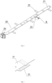
Fig. 2 is a structural schematic diagram showing connection between a circuit board in the battery module shown inFig. 1 and a temperature collection element and a reinforcing plate of the temperature measurement unit; -
Fig. 3 is a partial structural schematic diagram of a circuit board in the battery module shown inFig. 1 when an extending strip body is in a flattened state; -
Fig. 4 is an enlarged structural schematic diagram of part B inFig. 2 ; -
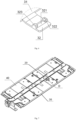
Fig. 5 is a structural schematic diagram of a harness plate in the battery module shown inFig. 1 ; -
Fig. 6 is an enlarged structural schematic diagram of part C inFig. 5 ; -
Fig. 7 is a structural schematic diagram of an assembly structure of a harness plate, a circuit board, an electrical connecting sheet and a temperature measurement unit in the battery module shown inFig. 1 ; -
Fig. 8 is an enlarged structural schematic diagram of part D inFig. 7 , wherein the electrical connecting sheet is not shown; -
Fig. 9 is a partial structural schematic diagram of an assembly structure of a harness plate, a circuit board, an electrical connecting sheet and a temperature measurement unit in the battery module shown inFig. 1 ; -
Fig. 10 is a structural schematic diagram of a bottom of the assembly structure shown inFig. 7 ; -
Fig. 11 is an enlarged structural schematic diagram of part E inFig. 10 ; -
Fig. 12 is a structural schematic diagram of a battery unit in the battery module shown inFig. 1 ; -
Fig. 13 is a partial structural schematic diagram along direction A-A ofFig. 1 . - A clear and complete description will be given below on the technical solutions in the embodiments of the present application in combination with accompanying drawings in the embodiments of the present application, and apparently the embodiments described below are only a part but not all of the embodiments of the present application. The description of at least one exemplary embodiment below is actually merely illustrative, rather than serving as any limitation to the present application and its applications or uses. Based upon the embodiments of the present application, all the other embodiments which can occur to those skilled in the art without any inventive effort shall all fall into the protection scope of the present application.
- Unless otherwise specified, the relative arrangement, numerical expressions and numerical values of the parts and steps described in these embodiments do not limit the scope of the present application. Meanwhile, it should be understood that, to facilitate description, the dimension of each part shown in the accompanying drawings is not drawn according to actual proportions. The techniques, methods and devices known to those skilled in the art may not be discussed in detail, however, under appropriate conditions, the description of techniques, methods and devices should be deemed as a part of the authorized description. In all the examples shown and discussed herein, any specific value should be explained as merely exemplary, rather than as a limitation. Therefore, other examples of the exemplary embodiments can have different values. It should be noted that, in the following drawings, similar reference numerals and letters represent similar items, therefore, once one item is defined in one accompanying drawing, then the item does not need to be further discussed in the subsequent accompanying drawings.
- In the description of the present application, it should be understood that, the orientation or positional relationship indicated by such terms as "front, rear, up, down, left, right", "lateral, longitudinal, vertical, horizontal", and "top, bottom" is merely for the convenience of description of the present application and simplified description, rather than indicating or implying that the device or element referred to must be located in a certain orientation or must be constructed or operated in a certain orientation without a statement to the contrary, therefore, the terms cannot be understood as a limitation to the protection scope of the present application; and such orientation terms as "inner, outside" mean inner or outside relative to the contour of each part itself.
- In the following description, the length direction of the battery module corresponds to the X direction shown in
Fig. 1 , the width direction of the battery module corresponds to the Y direction shown inFig. 1 , and the height direction of the battery module is the up and down direction and corresponds to the Z direction shown inFig. 1 . - As shown in
Fig. 1 to Fig. 13 , embodiments of the present application provide abattery module 1. Thebattery module 1 includes a plurality ofbattery units 10, atemperature measurement unit 90, aharness plate 30, acircuit board 20 and anelectrical connecting sheet 40. - The
battery unit 10 includes abattery top cover 15. Thetemperature measurement unit 90 includes atemperature collection element 91 configured to collect temperature of thebattery top cover 15. Theharness plate 30 is arranged on thebattery top cover 15 and includes aharness plate body 31 and a limitingstructure 32 arranged on theharness plate body 31. The limitingstructure 32 is matched with thetemperature measurement unit 90 to limit the position of thetemperature measurement unit 90. Thecircuit board 20 is arranged on theharness plate 30 and includes acircuit board body 21 and an extendingstrip 23 arranged on thecircuit board body 21. Thetemperature collection element 91 is connected with the extendingstrip 23 to transmit collected temperature signals to thecircuit board body 21 through the extendingstrip 23. The electrical connectingsheet 40 is configured to connectadjacent battery units 10 and is arranged on theharness plate 30. Thetemperature measurement unit 90 is arranged between the electrical connectingsheet 40 and thebattery top cover 15, and the electrical connectingsheet 40 exerts pressure onto thetemperature measurement unit 90, such that thetemperature measurement unit 90 is kept in fit with thebattery top cover 15. - In the
battery module 1 of the embodiment of the present application, since thetemperature collection element 91 collects temperature of thebattery unit 10 through collecting the temperature of thebattery top cover 15, compared with the temperature of the electrical connectingsheet 40, the temperature of thebattery top cover 15 is more approximate to the actual temperature inside thebattery unit 10, the temperature difference between the two can still be within an acceptable range even if under severe working conditions, for example, within 5°C, therefore, the temperature collected by thetemperature collection element 91 can more accurately reflect the actual temperature inside thebattery unit 10, thereby being beneficial for ensuring discharge power of thebattery module 1. In addition, since theharness plate 30 includes the limitingstructure 32 which is matched with thetemperature measurement unit 90 to limit the position of thetemperature measurement unit 90, thetemperature measurement unit 90 is arranged between the electrical connectingsheet 40 and thebattery top cover 15, the electrical connectingsheet 40 exerts pressure onto thetemperature measurement unit 90, such that thetemperature measurement unit 90 is kept in fit with thebattery top cover 15, thereby being beneficial for ensuring stable and reliable temperature transmission path between thebattery top cover 15 and thetemperature collection element 91, and further being beneficial for ensuring that thetemperature collection element 91 accurately collects the temperature of thebattery top cover 15 under various shocking or vibrating working conditions. As shown inFig. 1 ,Fig. 2 ,Fig. 4 ,Fig. 7 to Fig. 10 andFig. 13 , in some embodiments, the limitingstructure 32 is arranged between the electrical connectingsheet 40 and thebattery top cover 15, and the electrical connectingsheet 40 exerts pressure onto thetemperature measurement unit 90 through the limitingstructure 32. In the device, the electrical connectingsheet 40 does not directly press downwards against thetemperature measurement unit 90, the limitingstructure 32 directly bears the pressure of the electrical connectingsheet 40, and places such important parts of thetemperature measurement unit 90 as thetemperature collection element 91 under the protection of the limitingstructure 32, thereby being beneficial for improving reliability and prolonging service life of thetemperature measurement unit 90. - As shown in
Fig. 1 ,Fig. 2 ,Fig. 4 ,Fig. 7 to Fig. 10 andFig. 13 , in some embodiments, thetemperature measurement unit 90 further includes a reinforcingplate 92, wherein the reinforcingplate 92 is connected with the extendingstrip 23, a connecting area, on the extendingstrip 23, of thetemperature collection element 91 is within a connecting area, on the extendingstrip 23, of the reinforcingplate 92; the limitingstructure 32 is in limiting match with the reinforcingplate 92, and the electrical connectingsheet 40 exerts pressure onto the reinforcingplate 92 of thetemperature measurement unit 90 through a limitingstructure 32. In the arrangement, the limitingstructure 32 and the reinforcingplate 92 mainly bear the pressure of the electrical connectingsheet 40, on the one hand, the reinforcingplate 92 enhances the strength of the part at which the extendingstrip 23 is connected with thetemperature collection element 91, thereby being beneficial for reliable connection between thetemperature collection element 91 and the extendingstrip 23, and improving reliability of transmission of signals to thecircuit board 20 by thetemperature collection element 91, on the other hand, the reinforcingplate 92 bears the pressure of the electrical connectingsheet 40 on thetemperature measurement unit 90, thereby being beneficial for protecting thetemperature collection element 91 from damage of a mechanical force, and further being beneficial for improving reliability and prolonging service life of thetemperature measurement unit 90. - As shown in
Fig. 1 ,Fig. 2 ,Fig. 4 ,Fig. 7 to Fig. 10 andFig. 13 , in some embodiments, thetemperature collection element 91 and the reinforcingplate 92 are arranged at two sides of the extendingstrip 23 respectively. At this time, the reinforcingplate 92 can be arranged between the extendingstrip 23 and thebattery top cover 15, and can also be arranged between the extendingstrip 23 and the electrical connectingsheet 40. - In some embodiments, the
temperature collection element 91 and the reinforcingplate 92 are arranged on the same side of the extendingstrip 23, the reinforcingplate 92 includes an accommodating hole, and thetemperature collection element 91 is arranged in the accommodating hole. At this time, the reinforcingplate 92 and thetemperature collection element 91 can be arranged between the extendingstrip 23 and the battery top cover 15 or arranged between the extendingstrip 23 and the electrical connectingsheet 40. - Position changes of the
temperature collection element 91, the reinforcingplate 92 and the extendingstrip 23 can influence the temperature collection path or stress degree of thetemperature collection element 91, and the installation positions of thetemperature collection element 91 and the reinforcingplate 92 can be selected according to the temperature collection environment required by the temperature collection element. - As shown in
Fig. 5 to Fig. 10 andFig. 13 , in some embodiments, the limitingstructure 32 includes a limitingclamping groove 322, and the reinforcingplate 92 is installed in the limitingclamping groove 322. Connection between the limitingclamping groove 322 and the reinforcingplate 92 is beneficial for rapid assembly and disassembly of thetemperature measurement unit 90 and the limitingstructure 32. - As shown in
Fig. 5 to Fig. 10 andFig. 13 , in some embodiments, the limitingstructure 32 includes a limitingprotrusion 323 which protrudes towards the electrical connectingsheet 40, and the limitingprotrusion 323 is abutted against the electrical connectingsheet 40. The connection between the limitingprotrusion 323 and the electrical connectingsheet 40 is beneficial for controlling distance between the electrical connectingsheet 40 and thebattery top cover 15, and provides an installation space for thetemperature measurement unit 90, and is further beneficial for ensuring that key parts of thetemperature measurement unit 90 are not subjected to a mechanical damage. - As shown in
Fig. 10, Fig. 11 andFig. 13 , in some embodiments, thetemperature measurement unit 90 includes athermal conducting pad 93, and thethermal conducting pad 93 is arranged between thetemperature collection element 91 and thebattery top cover 15. Heat is transferred to thetemperature collection element 91 through thethermal conducting pad 93, a buffer layer can be formed between the battery top covers 15 and thetemperature collection element 91, thereby being beneficial for ensuring that heat conduction can still be maintained between thetemperature collection element 91 and the battery top cover 15 through thethermal conducting pad 93 under various shocking or vibrating working conditions, and further being beneficial for maintaining continuity and stability of temperature signal collection by thetemperature collection element 91. - As shown in
Fig. 5 ,Fig. 6 ,Fig. 10, Fig. 11 andFig. 13 , in some embodiments, the limitingstructure 32 includes a limitinghole 321, and thethermal conducting pad 93 is arranged in the limitinghole 321. Placement of thethermal conducting pad 93 in the limitinghole 321 is beneficial for limiting position of thethermal conducting pad 93, thereby effectively preventing thethermal conducting pad 93 and the temperature collection position on the battery top cover 15 or thetemperature collection element 91 from cutting off heat conduction, and being beneficial for maintaining continuity and stability of temperature signal collection by thetemperature collection element 91. - As shown in
Fig. 12 , in some embodiments, thebattery unit 10 includes atop sheet 14 arranged on thebattery top cover 15, and thetop sheet 14 is attached to an upper surface of thebattery top cover 15. On the one hand, thetop sheet 14 plays a role of insulation, and prevents short circuit between thebattery top cover 15 and the external circuit, on the other hand, thetop sheet 14 plays a role of protection, and prevents the battery top cover 15 from being scratched. To collect the surface temperature of thebattery top cover 15, thetop sheet 14 includes atemperature collection opening 141, and thetemperature measurement unit 90 is fit with the battery top cover 15 exposed from thetemperature collection opening 141. The setting can avoid influence of thetop sheet 14 on the temperature collection path of thetemperature collection element 91, thereby being beneficial for thetemperature collection element 91 to collect temperature of the battery top cover 15 more timely and accurately. - As shown in
Fig. 9 , in some embodiments, the electrical connectingsheet 40 includes an avoidinghole 41, and the avoidinghole 41 is configured to prevent contact between the electrical connectingsheet 40 and thetemperature collection element 91. The setting is beneficial for preventing heat exchange between the electrical connectingsheet 40 and thetemperature collection element 91, thereby being beneficial for improving accuracy in temperature collection by thetemperature collection element 91. - Embodiments of the present application will be further illustrated below in combination with
Fig. 1 to Fig. 13 . - As shown in
Fig. 1 to Fig. 13 , thebattery module 1 includes a plurality ofbattery units 10, acircuit board 20, aharness plate 30, an electrical connectingsheet 40, ashell 50 and atemperature measurement unit 90. - As shown in
Fig. 12 , thebattery unit 10 includes a battery housing, an electrode assembly (not shown in the figure), abattery top cover 15, apositive electrode terminal 11, anegative electrode terminal 12, ananti-explosion valve 13 and atop sheet 14. - As shown in
Fig. 5 andFig. 6 , theharness plate 30 includes aharness plate body 31 and a limitingstructure 32. - As shown in
Fig. 1 to Fig. 4 andFig. 13 , thecircuit board 20 includes acircuit board body 21, ametal sheet 22, an extendingstrip 23 and aconnector 24. - As shown in
Fig. 8, Fig. 9 ,Fig. 11 andFig. 13 , thetemperature measurement unit 90 includes atemperature collection element 91, a reinforcingplate 92 and athermal conducting pad 93. - A plurality of
battery units 10 are arranged side by side along a length direction X of thebattery module 1 in theshell 50. Theharness plate 30 is arranged above the plurality ofbattery units 10. Thecircuit board 20 is arranged above theharness plate 30. The length direction X and the width direction Y of theharness plate 30 are correspondingly consistent with the length direction X and the width direction Y of thebattery module 1. The electrical connectingsheet 40 is arranged above theharness plate 30. The number of the electrical connectingsheet 40 is determined according to the number of thebattery units 10, and the electrical connectingsheet 40 connects the electrode terminals ofadjacent battery units 10, to realize electrical connection between thebattery units 10. - The
circuit board 20 is a flexible printed circuit (FPC). Thecircuit board body 21 of thecircuit board 20 is strip-shaped, and is arranged in the middle position of the width direction Y of theharness plate 30, and the length direction X and the width direction Y of thecircuit board body 21 are consistent with the length direction X and the width direction Y of thebattery module 1. - The number of the
metal sheet 22 of thecircuit board 20 is consistent with the number of the electrical connectingsheet 40, and themetal sheet 22 is configured to connect the electrical connectingsheet 40 and thecircuit board 20. - The
connector 24 is arranged on an end of the length direction X of thecircuit board body 21, and is configured to connect the external circuit. - As shown in
Fig. 2 to Fig. 4 , the extendingstrip 23 of thecircuit board 20 includes an extendingstrip body 231 and an extendingstrip connecting part 232 which connects the extendingstrip body 231 and thecircuit board body 21. The extendingstrip connecting part 232 in the present embodiment is a section of connecting strip which extends along the width direction Y of thecircuit board 20. The extendingstrip 23 has the same material as thecircuit board body 21. - The extending
strip body 231 has a flattened state when thecircuit board 20 is not assembled into thebattery module 1 and a bending state when thecircuit board 20 is assembled into thebattery module 1. As shown inFig. 3 , in the flattened state, the length direction X of the extendingstrip body 231 is consistent with the length direction X of thecircuit board body 21. As shown inFig. 4 , in the bending state, the extendingstrip body 231 is bent to an L shape, the extendingstrip body 231 includes afirst part 231A which extends along the length direction X of thecircuit board 20 and asecond part 231B which extends along a width direction Y of thecircuit board body 21, and thetemperature collection element 91 is connected with thesecond part 231B. - The setting of the extending strip body along the length direction X of the
circuit board 20 when the extending strip body is in a flattened state is beneficial for reducing material cost of thecircuit board 20. The extending strip body is bent along a bending line L (refer toFig. 4 ) to form an L shape, and thesecond part 231B of the extendingstrip body 231 extends along the width direction Y, thereby being beneficial for ensuring that thetemperature collection element 91 on the tail end of 231B of the extendingstrip body 231 is just faced the position of the temperature collection opening 141 on thetop sheet 14 above thebattery top cover 15. - The
temperature collection element 91 in the present embodiment is an NTC (negative temperature coefficient) temperature sensor. Thetemperature collection element 91 is connected with the extendingstrip 23, to transmit temperature signals collected by thetemperature collection element 91 to the corresponding circuit in thecircuit board body 21. - As shown in
Fig. 8 , thetemperature collection element 91 and the reinforcingplate 92 are respectively arranged at two sides of the extendingstrip 23. The connecting area, on the extendingstrip 23, of thetemperature collection element 91 is within the connecting area, on the extendingstrip 23, of the reinforcingplate 92. - The reinforcing
plate 92 can enhance the strength of the position at which thetemperature collection element 91 is installed on the extendingstrip 23, and the reinforcingplate 92 is further configured to bear a counter-acting force produced by prepressing thethermal conducting pad 93. - The
thermal conducting pad 93 should have a high thermal conductivity coefficient and amount of compression, and can bear expansion and deformation of thebattery module 1 until the end of life (EOL) and the extrusion during shock or vibration. - As shown in
Fig. 12 , thetop sheet 14 fit on thebattery top cover 15 is provided with atemperature collection opening 141, and the part of the battery top cover 15 exposed at thetemperature collection opening 141 is in direct contact with thethermal conducting pad 93 of thetemperature measurement unit 90. - As shown in
Fig. 12 , the temperature collection opening 141 on thetop sheet 14 is arranged between thepositive electrode terminal 11 and thenegative electrode terminal 12 of thebattery unit 10, and is adjacent to thenegative electrode terminal 12, thereby being beneficial for more accurate collection of temperature of thebattery unit 10 by thetemperature collection element 91. - The limiting
structure 32 of theharness plate 30 limits position of thetemperature measurement unit 90, and simultaneously limits the position of the tail end of the extendingstrip 23 of thecircuit board 20. - The limiting
structure 32 of theharness plate 30 is arranged in anopening 311 of theharness plate body 31, and extends from the middle part of theharness plate body 31 to the side of the edge of theharness plate body 31 along the width direction Y of theharness plate body 31. The set position of the limitingstructure 32 is beneficial for realizing match between the limitingstructure 32 and the extendingstrip 23 as well as the electrical connectingsheet 40. - The limiting
structure 32 as a whole is of a plate-shaped structure, and includes a limitinghole 321, a limitingclamping groove 322 and a limitingprotrusion 323. The limitinghole 321 is arranged in the middle of the plate-shaped structure, and is a square hole. The limitingclamping groove 322 is formed by two L-shaped clamping blocks which are arranged correspondingly at two opposite edges of the limitinghole 321. Each of the top ends of the two L-shaped clamping blocks is provided with a limiting rib which protrudes upwards as a limitingprotrusion 323. - As shown in
Fig. 6 , the plate-shaped structure includes a first plate which sinks relative to theharness plate body 31 and a second plate which connects theharness plate body 31 and the first plate and which is gradually downwards from theharness plate body 31 to the first plate. The limitinghole 321, the limitingclamping groove 322 and the limitingprotrusion 323 are all arranged on the first plate. The setting is beneficial for better limiting the position of each component of thetemperature measurement unit 90. - The limiting
clamping groove 322 of the limitingstructure 32 locates the position of the reinforcingplate 92 of thetemperature measurement unit 90, to prevent up and down movement of the reinforcingplate 92 due to force. Thethermal conducting pad 93 is arranged in the limitinghole 321, and the side wall of the limitinghole 321 limits the positions of thethermal conducting pad 93 in the length direction X and the width direction Y The limiting rib serving as the limitingprotrusion 323 is fit with the lower surface of the electrical connectingsheet 40, and the electrical connectingsheet 40 presses tightly against the limitingstructure 32 and the reinforcingplate 92 connected with the limitingstructure 32, to prevent the limitingstructure 32 and the reinforcingplate 92 from upwarping, and further to prevent separation of thethermal conducting pad 93 arranged below the reinforcingplate 92 from thebattery top cover 15. - When the assembly structure above the
battery unit 10 of thebattery module 1 is assembled, after the electrical connectingsheet 40 is assembled on theharness plate 30, thecircuit board 20 and thetemperature measurement unit 90 are then assembled, the reinforcingplate 92 is installed in the limitingclamping groove 322, and then the avoidinghole 41 of the electrical connectingsheet 40 corresponds to the position of thetemperature collection element 91. - The electrical connecting
sheet 40 is provided with an avoidinghole 41 to avoid from thetemperature collection element 91, so as to avoid transmission of the temperature of the electrical connectingsheet 40 to thetemperature collection element 91. The electrical connectingsheet 40 pressing the limitingprotrusion 323 of the limitingstructure 32 should not be influenced by the forming of the avoidinghole 41, to ensure that the electrical connectingsheet 40 presses downwards against the reinforcingplate 92 through pressing against the limitingprotrusion 323, so as to press downwards against thetemperature measurement unit 90. - After the above assembly steps are finished, the well-assembled assembly structure is turned over, a
thermal conducting pad 93 is pasted on the back side of the reinforcingplate 92, and thethermal conducting pad 93 is placed in the limitinghole 321 of the limitingstructure 32, to make it easy for a hole wall of the limitinghole 321 to limit displacement of thethermal conducting pad 93. Of course, thethermal conducting pad 93 can also be directly pasted at the temperature collection position of thebattery top cover 15, and after the above well-assembled assembly and thebattery unit 10 are assembled, contact between thethermal conducting pad 93 and the reinforcingplate 92 or thetemperature collection element 91 can also be realized. Thethermal conducting pad 93 may also be self-adhesive, and may be manufactured from silicone rubber. Such type of thermal conducting pad can be bonded with thebattery top cover 15 and the reinforcingplate 92 through no adhesive layer, thereby shortening the temperature collection path of thetemperature collection element 91. - In the present embodiment, the thickness of the
thermal conducting pad 93 should be greater than the gap between the reinforcingplate 92 and the top cover, to ensure that the temperature collection path of thetemperature collection element 91 is kept smooth. The initial thickness of thethermal conducting pad 93 can be set in consideration with shoulder height tolerance of the battery and deformations under various working conditions. After the above well-assembled assembly structure and the battery unit are assembled, each electrical connectingsheet 40 and the corresponding electrode terminals of thebattery units 10 are welded. - After the electrical connecting
sheet 40 is welded with the corresponding electrode terminals, the position of the electrical connectingsheet 40 in the height direction is defined, through pressing tightly against the limitingprotrusion 323 of the limitingstructure 32 through the lower surface of the electrical connectingsheet 40, thethermal conducting pad 93 below the reinforcingplate 92 and thebattery top cover 15 form interference contact, to ensure that the temperature collection path between thebattery top cover 15 and thetemperature collection element 91 is kept smooth, and improve reliability of temperature collection. - In the
battery module 1 of the embodiment of the present application, thetemperature collection element 91 realizes temperature collection of thebattery unit 10 through collecting temperature of thebattery top cover 15. Compared with the temperature of the electrical connectingsheet 40, the temperature of thebattery top cover 15 is more approximate to the actual temperature inside thebattery unit 10, thereby being beneficial for ensuring the discharge power of thebattery module 1. The heat transfer path in the temperature collection process is effectively shortened compared with the prior art, thereby being beneficial for improving accuracy and response speed of temperature collection. Thetemperature measurement unit 90 ensures stable and reliable temperature transmission path between thebattery top cover 15 and thetemperature collection element 91 through thethermal conducting pad 93 and the reinforcingplate 92, and can ensure that thetemperature collection element 91 accurately collects the temperature of thebattery top cover 15 under various shocking or vibrating working conditions. - Embodiments of the present application further provide a device, including the battery module described above, and the battery module is configured to provide electric energy. Wherein the device can be a vehicle or an energy-storage device.
Claims (14)
- A battery module, comprising:a plurality of battery units (10), comprising a battery top cover (15);a temperature measurement unit (90), comprising a temperature collection element (91) configured to collect temperature of the battery top cover (15);a harness plate (30), arranged on the battery top cover (15) and comprising a harness plate body (31) and a limiting structure (32) arranged on the harness plate body (31), wherein the limiting structure (32) is configured to cooperate with the temperature measurement unit (90) to limit the position of the temperature measurement unit (90);a circuit board (20), arranged on the harness plate (30) and comprising a circuit board body (21) and an extending strip (23) arranged on the circuit board body (21), wherein the temperature collection element (91) is connected with the extending strip (23) to transmit collected temperature signals to the circuit board body (21) through the extending strip (23); andan electrical connecting sheet (40), connecting adjacent battery units (10) and arranged on the harness plate (30);characterized in that:the temperature measurement unit (90) is arranged between the electrical connecting sheet (40) and the battery top cover (15), and the electrical connecting sheet (40) is configured to exert pressure onto the temperature measurement unit (90), such that the temperature measurement unit (90) is kept in fit with the battery top cover (15); andwherein the limiting structure (32) is arranged between the electrical connecting sheet (40) and the battery top cover (15), and the electrical connecting sheet (40) is configured to exert pressure onto the temperature measurement unit (90) through the limiting structure (32).
- The battery module according to claim 1, wherein the temperature measurement unit (90) comprises a reinforcing plate (92), wherein the reinforcing plate (92) is connected with the extending strip (23), a connecting area, on the extending strip (23), of the temperature collection element (91) is within a connecting area, on the extending strip (23), of the reinforcing plate (92), the limiting structure (32) is fitted with the reinforcing plate (92) in a limiting manner, and the electrical connecting sheet (40) is configured to exert pressure onto the reinforcing plate (92) of the temperature measurement unit (90) through the limiting structure (32).
- The battery module according to claim 2, wherein the temperature collection element (91) and the reinforcing plate (92) are arranged at two sides of the extending strip (23) respectively.
- The battery module according to claim 2, wherein the temperature collection element (91) and the reinforcing plate (92) are arranged at the same side of the extending strip (23), the reinforcing plate (92) comprises an accommodating hole in which the temperature collection element (91) is located.
- The battery module according to any one of claims 2-4, wherein the limiting structure (32) comprises a limiting clamping groove (322), and the reinforcing plate (92) is arranged in the limiting clamping groove (322).
- The battery module according to any one of claims 1-5, wherein the limiting structure (32) comprises a limiting protrusion (323) which is configured to protrude towards the electrical connecting sheet (40), and the limiting protrusion (323) is configured to abut against the electrical connecting sheet (40).
- The battery module according to any one of claims 1-6, wherein the temperature measurement unit (90) comprises a thermal conducting pad (93), and the thermal conducting pad (93) is arranged between the temperature collection element (91) and the battery top cover (15).
- The battery module according to claim 7, wherein the limiting structure (32) comprises a limiting hole (321) in which the thermal conducting pad (93) is located.
- The battery module according to any one of claims 2-6, wherein the temperature measurement unit (90) comprises a thermal conducting pad (93), the thermal conducting pad (93) is arranged between the reinforcing plate (92) and the battery top cover (15), the thermal conducting pad (93) is an elastic pad, and the thickness of the thermal conducting pad (93) in the original state is greater than the distance between the reinforcing plate (92) and the battery top cover (15).
- The battery module according to any one of claims 1-9, wherein the extending strip (23) comprises an extending strip body (231) and an extending strip connecting part (232) which is configured to connect the extending strip body (231) with the circuit board body (21), the extending strip body (231) is bent to be L-shaped, the extending strip body (231) comprises a first part (231A) which is configured to extend along a length direction (X) of the circuit board (20) and a second part (231B) which is configured to extend along a width direction (Y) of the circuit board body (21), and the temperature collection element (91) is connected with the second part (231B).
- The battery module according to any one of claims 1-10, wherein the battery unit (10) comprises a top sheet (14) fit with the battery top cover (15), the top sheet (14) comprises a temperature collection opening (141), and the temperature measurement unit (90) is fit with the battery top cover (15) exposed at the temperature collection opening (141).
- The battery module according to any one of claims 1-11, wherein the electrical connecting sheet (40) comprises an avoiding hole (41), and the avoiding hole (41) is configured to prevent contact between the electrical connecting sheet (40) and the temperature collection element (91).
- The battery module according to any one of claims 1-12, wherein the limiting structure (32) is arranged in an opening (311) of the harness plate body (31), and is configured to extend from the middle part of the harness plate body (31) towards one side of the edge along a width direction (Y) of the harness plate body (31).
- A device, comprising the battery module according to any one of claims 1-13, wherein the battery module is configured to provide electric energy.
Applications Claiming Priority (2)
| Application Number | Priority Date | Filing Date | Title |
|---|---|---|---|
| CN201910575254.9A CN112151703B (en) | 2019-06-28 | 2019-06-28 | battery module |
| PCT/CN2020/092177 WO2020259171A1 (en) | 2019-06-28 | 2020-05-25 | Battery module and device |
Publications (3)
| Publication Number | Publication Date |
|---|---|
| EP3800729A1 EP3800729A1 (en) | 2021-04-07 |
| EP3800729A4 EP3800729A4 (en) | 2021-09-22 |
| EP3800729B1 true EP3800729B1 (en) | 2025-02-26 |
Family
ID=73869329
Family Applications (1)
| Application Number | Title | Priority Date | Filing Date |
|---|---|---|---|
| EP20828249.1A Active EP3800729B1 (en) | 2019-06-28 | 2020-05-25 | Battery module and device |
Country Status (4)
| Country | Link |
|---|---|
| US (1) | US11923565B2 (en) |
| EP (1) | EP3800729B1 (en) |
| CN (1) | CN112151703B (en) |
| WO (1) | WO2020259171A1 (en) |
Families Citing this family (13)
| Publication number | Priority date | Publication date | Assignee | Title |
|---|---|---|---|---|
| CN216529128U (en) * | 2021-12-21 | 2022-05-13 | 中创新航科技股份有限公司 | Battery pack |
| JP2025504742A (en) * | 2022-01-31 | 2025-02-19 | ディール、アーカーオー、シュティフトゥング、ウント、コンパニー、コマンディトゲゼルシャフト | CELL CONTACT SYSTEM FOR A BATTERY MODULE AND METHOD FOR MANUFACTURING SUCH CELL CONTACT SYSTEM - Patent application |
| CN116632390A (en) * | 2022-02-14 | 2023-08-22 | 莫仕连接器(成都)有限公司 | Battery connection module |
| KR20230174571A (en) * | 2022-06-21 | 2023-12-28 | 삼성에스디아이 주식회사 | Battery pack |
| CN115117489B (en) * | 2022-08-02 | 2025-08-08 | 广汽埃安新能源汽车股份有限公司 | A temperature and voltage acquisition method, a temperature and voltage acquisition component, and a battery module |
| DE102022129500A1 (en) | 2022-11-08 | 2024-05-08 | Daimler Truck AG | Battery module with at least two individual battery cells |
| CN116786375B (en) * | 2023-06-29 | 2025-12-19 | 上汽大众汽车有限公司 | Gluing device and gluing method for battery pack heat-conducting glue |
| CN220856856U (en) * | 2023-08-25 | 2024-04-26 | 惠州亿纬锂能股份有限公司 | CCS assembly and battery module |
| CN116936943B (en) * | 2023-09-15 | 2023-12-19 | 海目星激光科技集团股份有限公司 | Cell heating device and method |
| KR20250040219A (en) * | 2023-09-15 | 2025-03-24 | 삼성에스디아이 주식회사 | Battery module |
| KR20250073703A (en) * | 2023-11-20 | 2025-05-27 | 삼성에스디아이 주식회사 | Temperature measurement apparatus and battery module including the same |
| WO2025077361A1 (en) * | 2024-05-27 | 2025-04-17 | 惠州亿纬锂能股份有限公司 | Temperature collection assembly and battery |
| CN118687698B (en) * | 2024-07-11 | 2024-12-03 | 江苏正力新能电池技术股份有限公司 | Collection components and battery packs |
Family Cites Families (16)
| Publication number | Priority date | Publication date | Assignee | Title |
|---|---|---|---|---|
| JP4778481B2 (en) * | 2007-06-07 | 2011-09-21 | 矢崎総業株式会社 | Temperature detector mounting structure |
| JP2010257775A (en) * | 2009-04-24 | 2010-11-11 | Sanyo Electric Co Ltd | Battery module, battery system and electric vehicle |
| CN102544616B (en) * | 2010-12-08 | 2014-07-30 | 比亚迪股份有限公司 | Battery module |
| KR101669116B1 (en) * | 2011-12-01 | 2016-10-26 | 삼성에스디아이 주식회사 | Battery module having sensing member |
| CN202495555U (en) * | 2012-02-16 | 2012-10-17 | 东莞新能源电子科技有限公司 | A temperature and voltage detection device for a battery pack |
| KR101708365B1 (en) | 2013-09-13 | 2017-02-20 | 삼성에스디아이 주식회사 | Battery pack |
| JP6163261B2 (en) * | 2014-05-29 | 2017-07-12 | 日立オートモティブシステムズ株式会社 | Power storage module |
| US9646745B2 (en) * | 2014-07-29 | 2017-05-09 | Ford Global Technologies, Llc | Thermistor assembly including elastomeric body |
| JP6233654B2 (en) * | 2014-11-25 | 2017-11-22 | 株式会社オートネットワーク技術研究所 | Wiring module |
| CN206806468U (en) * | 2017-05-15 | 2017-12-26 | 宁德时代新能源科技股份有限公司 | Battery modules |
| CN207116634U (en) | 2017-09-06 | 2018-03-16 | 宁德时代新能源科技股份有限公司 | Battery modules |
| CN207183388U (en) * | 2017-09-21 | 2018-04-03 | 宁德时代新能源科技股份有限公司 | battery module |
| CN207558994U (en) * | 2017-11-29 | 2018-06-29 | 长城汽车股份有限公司 | Battery modules component and battery pack |
| CN207779574U (en) * | 2018-01-31 | 2018-08-28 | 长城汽车股份有限公司 | Heat detector mounting assembly and battery for battery |
| CN207781834U (en) * | 2018-02-08 | 2018-08-28 | 力神动力电池系统有限公司 | A kind of power battery module with novel battery acquisition system |
| CN108417766A (en) * | 2018-05-18 | 2018-08-17 | 中兴高能技术有限责任公司 | Composite sheet, battery modules and battery management system is isolated in harness |
-
2019
- 2019-06-28 CN CN201910575254.9A patent/CN112151703B/en active Active
-
2020
- 2020-05-25 WO PCT/CN2020/092177 patent/WO2020259171A1/en not_active Ceased
- 2020-05-25 EP EP20828249.1A patent/EP3800729B1/en active Active
-
2021
- 2021-01-04 US US17/140,842 patent/US11923565B2/en active Active
Also Published As
| Publication number | Publication date |
|---|---|
| CN112151703B (en) | 2022-03-11 |
| US20210126327A1 (en) | 2021-04-29 |
| EP3800729A1 (en) | 2021-04-07 |
| CN112151703A (en) | 2020-12-29 |
| EP3800729A4 (en) | 2021-09-22 |
| WO2020259171A1 (en) | 2020-12-30 |
| US11923565B2 (en) | 2024-03-05 |
Similar Documents
| Publication | Publication Date | Title |
|---|---|---|
| EP3800729B1 (en) | Battery module and device | |
| US11450897B2 (en) | Battery module | |
| EP3063822B1 (en) | Signal collection and power connection assembly | |
| CN210628444U (en) | Battery module, battery pack, and vehicle | |
| US20250226469A1 (en) | Battery module and battery pack | |
| CN215732084U (en) | Sampling assembly of battery module and battery module | |
| CN209822826U (en) | Sampling device for battery module and battery module | |
| CN210744091U (en) | Battery module, battery pack, and device | |
| US11894525B2 (en) | Battery module and vehicle | |
| CN114430079B (en) | Battery packs and electrical devices | |
| EP3799192B1 (en) | Battery module and apparatus | |
| US20250174802A1 (en) | Battery pack and electric device | |
| WO2023123047A1 (en) | Battery, power consuming device, and method for manufacturing battery | |
| US20240332674A1 (en) | Heating device, electrochemical device, and electrical device | |
| CN218677504U (en) | Signal sampling assembly for battery module and battery module | |
| CN218040863U (en) | Battery protection board and battery packaging structure | |
| CN216213938U (en) | Battery assembly and movable platform comprising same | |
| CN223911732U (en) | Top cap subassembly, electric core and battery package of electric core | |
| CN224153558U (en) | Data acquisition components and battery modules | |
| CN224153547U (en) | Battery devices and electrical equipment | |
| CN220456596U (en) | Wire harness board integrated component, battery module and vehicle | |
| CN223858272U (en) | Energy storage device | |
| CN221961046U (en) | Battery protection board components, batteries and electronic equipment | |
| CN222620075U (en) | Battery cell temperature acquisition structure, battery module and power battery | |
| CN217933929U (en) | Tab folding mechanism for battery |
Legal Events
| Date | Code | Title | Description |
|---|---|---|---|
| STAA | Information on the status of an ep patent application or granted ep patent |
Free format text: STATUS: UNKNOWN |
|
| STAA | Information on the status of an ep patent application or granted ep patent |
Free format text: STATUS: THE INTERNATIONAL PUBLICATION HAS BEEN MADE |
|
| PUAI | Public reference made under article 153(3) epc to a published international application that has entered the european phase |
Free format text: ORIGINAL CODE: 0009012 |
|
| STAA | Information on the status of an ep patent application or granted ep patent |
Free format text: STATUS: REQUEST FOR EXAMINATION WAS MADE |
|
| 17P | Request for examination filed |
Effective date: 20201231 |
|
| AK | Designated contracting states |
Kind code of ref document: A1 Designated state(s): AL AT BE BG CH CY CZ DE DK EE ES FI FR GB GR HR HU IE IS IT LI LT LU LV MC MK MT NL NO PL PT RO RS SE SI SK SM TR |
|
| AX | Request for extension of the european patent |
Extension state: BA ME |
|
| A4 | Supplementary search report drawn up and despatched |
Effective date: 20210819 |
|
| RIC1 | Information provided on ipc code assigned before grant |
Ipc: H01M 10/48 20060101ALI20210813BHEP Ipc: H01M 10/42 20060101ALI20210813BHEP Ipc: H01M 50/50 20210101ALI20210813BHEP Ipc: H01M 50/20 20210101ALI20210813BHEP Ipc: H01M 50/147 20210101AFI20210813BHEP |
|
| DAV | Request for validation of the european patent (deleted) | ||
| DAX | Request for extension of the european patent (deleted) | ||
| REG | Reference to a national code |
Ref country code: DE Ref legal event code: R079 Ref document number: 602020046897 Country of ref document: DE Free format text: PREVIOUS MAIN CLASS: H01M0050147000 Ipc: H01M0010480000 |
|
| RIC1 | Information provided on ipc code assigned before grant |
Ipc: H01M 50/569 20210101ALI20240701BHEP Ipc: H01M 50/519 20210101ALI20240701BHEP Ipc: H01M 50/505 20210101ALI20240701BHEP Ipc: H01M 50/289 20210101ALI20240701BHEP Ipc: H01M 50/271 20210101ALI20240701BHEP Ipc: H01M 50/209 20210101ALI20240701BHEP Ipc: H01M 10/653 20140101ALI20240701BHEP Ipc: H01M 10/42 20060101ALI20240701BHEP Ipc: H01M 10/04 20060101ALI20240701BHEP Ipc: H01M 10/48 20060101AFI20240701BHEP |
|
| GRAP | Despatch of communication of intention to grant a patent |
Free format text: ORIGINAL CODE: EPIDOSNIGR1 |
|
| STAA | Information on the status of an ep patent application or granted ep patent |
Free format text: STATUS: GRANT OF PATENT IS INTENDED |
|
| RAP1 | Party data changed (applicant data changed or rights of an application transferred) |
Owner name: CONTEMPORARY AMPEREX TECHNOLOGY(HONG KONG) LIMITED |
|
| INTG | Intention to grant announced |
Effective date: 20240917 |
|
| GRAS | Grant fee paid |
Free format text: ORIGINAL CODE: EPIDOSNIGR3 |
|
| GRAA | (expected) grant |
Free format text: ORIGINAL CODE: 0009210 |
|
| STAA | Information on the status of an ep patent application or granted ep patent |
Free format text: STATUS: THE PATENT HAS BEEN GRANTED |
|
| AK | Designated contracting states |
Kind code of ref document: B1 Designated state(s): AL AT BE BG CH CY CZ DE DK EE ES FI FR GB GR HR HU IE IS IT LI LT LU LV MC MK MT NL NO PL PT RO RS SE SI SK SM TR |
|
| REG | Reference to a national code |
Ref country code: GB Ref legal event code: FG4D |
|
| REG | Reference to a national code |
Ref country code: CH Ref legal event code: EP |
|
| REG | Reference to a national code |
Ref country code: DE Ref legal event code: R096 Ref document number: 602020046897 Country of ref document: DE |
|
| REG | Reference to a national code |
Ref country code: IE Ref legal event code: FG4D |
|
| P01 | Opt-out of the competence of the unified patent court (upc) registered |
Free format text: CASE NUMBER: APP_19235/2025 Effective date: 20250422 |
|
| REG | Reference to a national code |
Ref country code: NL Ref legal event code: MP Effective date: 20250226 |
|
| PG25 | Lapsed in a contracting state [announced via postgrant information from national office to epo] |
Ref country code: RS Free format text: LAPSE BECAUSE OF FAILURE TO SUBMIT A TRANSLATION OF THE DESCRIPTION OR TO PAY THE FEE WITHIN THE PRESCRIBED TIME-LIMIT Effective date: 20250526 |
|
| PG25 | Lapsed in a contracting state [announced via postgrant information from national office to epo] |
Ref country code: FI Free format text: LAPSE BECAUSE OF FAILURE TO SUBMIT A TRANSLATION OF THE DESCRIPTION OR TO PAY THE FEE WITHIN THE PRESCRIBED TIME-LIMIT Effective date: 20250226 |
|
| PG25 | Lapsed in a contracting state [announced via postgrant information from national office to epo] |
Ref country code: PL Free format text: LAPSE BECAUSE OF FAILURE TO SUBMIT A TRANSLATION OF THE DESCRIPTION OR TO PAY THE FEE WITHIN THE PRESCRIBED TIME-LIMIT Effective date: 20250226 |
|
| PGFP | Annual fee paid to national office [announced via postgrant information from national office to epo] |
Ref country code: DE Payment date: 20250516 Year of fee payment: 6 |
|
| PG25 | Lapsed in a contracting state [announced via postgrant information from national office to epo] |
Ref country code: ES Free format text: LAPSE BECAUSE OF FAILURE TO SUBMIT A TRANSLATION OF THE DESCRIPTION OR TO PAY THE FEE WITHIN THE PRESCRIBED TIME-LIMIT Effective date: 20250226 |
|
| REG | Reference to a national code |
Ref country code: LT Ref legal event code: MG9D |
|
| PG25 | Lapsed in a contracting state [announced via postgrant information from national office to epo] |
Ref country code: NO Free format text: LAPSE BECAUSE OF FAILURE TO SUBMIT A TRANSLATION OF THE DESCRIPTION OR TO PAY THE FEE WITHIN THE PRESCRIBED TIME-LIMIT Effective date: 20250526 Ref country code: IS Free format text: LAPSE BECAUSE OF FAILURE TO SUBMIT A TRANSLATION OF THE DESCRIPTION OR TO PAY THE FEE WITHIN THE PRESCRIBED TIME-LIMIT Effective date: 20250626 |
|
| PG25 | Lapsed in a contracting state [announced via postgrant information from national office to epo] |
Ref country code: NL Free format text: LAPSE BECAUSE OF FAILURE TO SUBMIT A TRANSLATION OF THE DESCRIPTION OR TO PAY THE FEE WITHIN THE PRESCRIBED TIME-LIMIT Effective date: 20250226 |
|
| PG25 | Lapsed in a contracting state [announced via postgrant information from national office to epo] |
Ref country code: HR Free format text: LAPSE BECAUSE OF FAILURE TO SUBMIT A TRANSLATION OF THE DESCRIPTION OR TO PAY THE FEE WITHIN THE PRESCRIBED TIME-LIMIT Effective date: 20250226 |
|
| PG25 | Lapsed in a contracting state [announced via postgrant information from national office to epo] |
Ref country code: LV Free format text: LAPSE BECAUSE OF FAILURE TO SUBMIT A TRANSLATION OF THE DESCRIPTION OR TO PAY THE FEE WITHIN THE PRESCRIBED TIME-LIMIT Effective date: 20250226 Ref country code: PT Free format text: LAPSE BECAUSE OF FAILURE TO SUBMIT A TRANSLATION OF THE DESCRIPTION OR TO PAY THE FEE WITHIN THE PRESCRIBED TIME-LIMIT Effective date: 20250626 |
|
| PGFP | Annual fee paid to national office [announced via postgrant information from national office to epo] |
Ref country code: FR Payment date: 20250519 Year of fee payment: 6 |
|
| PG25 | Lapsed in a contracting state [announced via postgrant information from national office to epo] |
Ref country code: BG Free format text: LAPSE BECAUSE OF FAILURE TO SUBMIT A TRANSLATION OF THE DESCRIPTION OR TO PAY THE FEE WITHIN THE PRESCRIBED TIME-LIMIT Effective date: 20250226 Ref country code: GR Free format text: LAPSE BECAUSE OF FAILURE TO SUBMIT A TRANSLATION OF THE DESCRIPTION OR TO PAY THE FEE WITHIN THE PRESCRIBED TIME-LIMIT Effective date: 20250527 |
|
| REG | Reference to a national code |
Ref country code: AT Ref legal event code: MK05 Ref document number: 1771590 Country of ref document: AT Kind code of ref document: T Effective date: 20250226 |
|
| PG25 | Lapsed in a contracting state [announced via postgrant information from national office to epo] |
Ref country code: SE Free format text: LAPSE BECAUSE OF FAILURE TO SUBMIT A TRANSLATION OF THE DESCRIPTION OR TO PAY THE FEE WITHIN THE PRESCRIBED TIME-LIMIT Effective date: 20250226 |
|
| PG25 | Lapsed in a contracting state [announced via postgrant information from national office to epo] |
Ref country code: SM Free format text: LAPSE BECAUSE OF FAILURE TO SUBMIT A TRANSLATION OF THE DESCRIPTION OR TO PAY THE FEE WITHIN THE PRESCRIBED TIME-LIMIT Effective date: 20250226 |
|
| PG25 | Lapsed in a contracting state [announced via postgrant information from national office to epo] |
Ref country code: DK Free format text: LAPSE BECAUSE OF FAILURE TO SUBMIT A TRANSLATION OF THE DESCRIPTION OR TO PAY THE FEE WITHIN THE PRESCRIBED TIME-LIMIT Effective date: 20250226 |
|
| PG25 | Lapsed in a contracting state [announced via postgrant information from national office to epo] |
Ref country code: IT Free format text: LAPSE BECAUSE OF FAILURE TO SUBMIT A TRANSLATION OF THE DESCRIPTION OR TO PAY THE FEE WITHIN THE PRESCRIBED TIME-LIMIT Effective date: 20250226 |
|
| PG25 | Lapsed in a contracting state [announced via postgrant information from national office to epo] |
Ref country code: AT Free format text: LAPSE BECAUSE OF FAILURE TO SUBMIT A TRANSLATION OF THE DESCRIPTION OR TO PAY THE FEE WITHIN THE PRESCRIBED TIME-LIMIT Effective date: 20250226 |
|
| PG25 | Lapsed in a contracting state [announced via postgrant information from national office to epo] |
Ref country code: CZ Free format text: LAPSE BECAUSE OF FAILURE TO SUBMIT A TRANSLATION OF THE DESCRIPTION OR TO PAY THE FEE WITHIN THE PRESCRIBED TIME-LIMIT Effective date: 20250226 Ref country code: EE Free format text: LAPSE BECAUSE OF FAILURE TO SUBMIT A TRANSLATION OF THE DESCRIPTION OR TO PAY THE FEE WITHIN THE PRESCRIBED TIME-LIMIT Effective date: 20250226 |
|
| PG25 | Lapsed in a contracting state [announced via postgrant information from national office to epo] |
Ref country code: RO Free format text: LAPSE BECAUSE OF FAILURE TO SUBMIT A TRANSLATION OF THE DESCRIPTION OR TO PAY THE FEE WITHIN THE PRESCRIBED TIME-LIMIT Effective date: 20250226 |
|
| PG25 | Lapsed in a contracting state [announced via postgrant information from national office to epo] |
Ref country code: SK Free format text: LAPSE BECAUSE OF FAILURE TO SUBMIT A TRANSLATION OF THE DESCRIPTION OR TO PAY THE FEE WITHIN THE PRESCRIBED TIME-LIMIT Effective date: 20250226 |
|
| REG | Reference to a national code |
Ref country code: DE Ref legal event code: R097 Ref document number: 602020046897 Country of ref document: DE |
|
| REG | Reference to a national code |
Ref country code: CH Ref legal event code: H13 Free format text: ST27 STATUS EVENT CODE: U-0-0-H10-H13 (AS PROVIDED BY THE NATIONAL OFFICE) Effective date: 20251223 |
|
| PLBE | No opposition filed within time limit |
Free format text: ORIGINAL CODE: 0009261 |
|
| STAA | Information on the status of an ep patent application or granted ep patent |
Free format text: STATUS: NO OPPOSITION FILED WITHIN TIME LIMIT |
|
| PG25 | Lapsed in a contracting state [announced via postgrant information from national office to epo] |
Ref country code: LU Free format text: LAPSE BECAUSE OF NON-PAYMENT OF DUE FEES Effective date: 20250525 |
|
| PG25 | Lapsed in a contracting state [announced via postgrant information from national office to epo] |
Ref country code: CH Free format text: LAPSE BECAUSE OF NON-PAYMENT OF DUE FEES Effective date: 20250531 |
|
| REG | Reference to a national code |
Ref country code: BE Ref legal event code: MM Effective date: 20250531 |
|
| PG25 | Lapsed in a contracting state [announced via postgrant information from national office to epo] |
Ref country code: MC Free format text: LAPSE BECAUSE OF FAILURE TO SUBMIT A TRANSLATION OF THE DESCRIPTION OR TO PAY THE FEE WITHIN THE PRESCRIBED TIME-LIMIT Effective date: 20250226 |
|
| 26N | No opposition filed |
Effective date: 20251127 |
|
| PGFP | Annual fee paid to national office [announced via postgrant information from national office to epo] |
Ref country code: GB Payment date: 20260331 Year of fee payment: 7 |
|
| PG25 | Lapsed in a contracting state [announced via postgrant information from national office to epo] |
Ref country code: IE Free format text: LAPSE BECAUSE OF NON-PAYMENT OF DUE FEES Effective date: 20250525 |
|
| PG25 | Lapsed in a contracting state [announced via postgrant information from national office to epo] |
Ref country code: BE Free format text: LAPSE BECAUSE OF NON-PAYMENT OF DUE FEES Effective date: 20250531 |