EP3800704B1 - Battery module and battery pack - Google Patents
Battery module and battery pack Download PDFInfo
- Publication number
- EP3800704B1 EP3800704B1 EP19907322.2A EP19907322A EP3800704B1 EP 3800704 B1 EP3800704 B1 EP 3800704B1 EP 19907322 A EP19907322 A EP 19907322A EP 3800704 B1 EP3800704 B1 EP 3800704B1
- Authority
- EP
- European Patent Office
- Prior art keywords
- battery
- battery module
- face
- vertical direction
- binding strip
- Prior art date
- Legal status (The legal status is an assumption and is not a legal conclusion. Google has not performed a legal analysis and makes no representation as to the accuracy of the status listed.)
- Active
Links
Images




Classifications
-
- H—ELECTRICITY
- H01—ELECTRIC ELEMENTS
- H01M—PROCESSES OR MEANS, e.g. BATTERIES, FOR THE DIRECT CONVERSION OF CHEMICAL ENERGY INTO ELECTRICAL ENERGY
- H01M50/00—Constructional details or processes of manufacture of the non-active parts of electrochemical cells other than fuel cells, e.g. hybrid cells
- H01M50/10—Primary casings; Jackets or wrappings
- H01M50/147—Lids or covers
- H01M50/166—Lids or covers characterised by the methods of assembling casings with lids
- H01M50/171—Lids or covers characterised by the methods of assembling casings with lids using adhesives or sealing agents
-
- H—ELECTRICITY
- H01—ELECTRIC ELEMENTS
- H01M—PROCESSES OR MEANS, e.g. BATTERIES, FOR THE DIRECT CONVERSION OF CHEMICAL ENERGY INTO ELECTRICAL ENERGY
- H01M50/00—Constructional details or processes of manufacture of the non-active parts of electrochemical cells other than fuel cells, e.g. hybrid cells
- H01M50/10—Primary casings; Jackets or wrappings
- H01M50/183—Sealing members
- H01M50/184—Sealing members characterised by their shape or structure
-
- H—ELECTRICITY
- H01—ELECTRIC ELEMENTS
- H01M—PROCESSES OR MEANS, e.g. BATTERIES, FOR THE DIRECT CONVERSION OF CHEMICAL ENERGY INTO ELECTRICAL ENERGY
- H01M50/00—Constructional details or processes of manufacture of the non-active parts of electrochemical cells other than fuel cells, e.g. hybrid cells
- H01M50/20—Mountings; Secondary casings or frames; Racks, modules or packs; Suspension devices; Shock absorbers; Transport or carrying devices; Holders
- H01M50/204—Racks, modules or packs for multiple batteries or multiple cells
- H01M50/207—Racks, modules or packs for multiple batteries or multiple cells characterised by their shape
- H01M50/209—Racks, modules or packs for multiple batteries or multiple cells characterised by their shape adapted for prismatic or rectangular cells
-
- H—ELECTRICITY
- H01—ELECTRIC ELEMENTS
- H01M—PROCESSES OR MEANS, e.g. BATTERIES, FOR THE DIRECT CONVERSION OF CHEMICAL ENERGY INTO ELECTRICAL ENERGY
- H01M50/00—Constructional details or processes of manufacture of the non-active parts of electrochemical cells other than fuel cells, e.g. hybrid cells
- H01M50/20—Mountings; Secondary casings or frames; Racks, modules or packs; Suspension devices; Shock absorbers; Transport or carrying devices; Holders
- H01M50/233—Mountings; Secondary casings or frames; Racks, modules or packs; Suspension devices; Shock absorbers; Transport or carrying devices; Holders characterised by physical properties of casings or racks, e.g. dimensions
- H01M50/242—Mountings; Secondary casings or frames; Racks, modules or packs; Suspension devices; Shock absorbers; Transport or carrying devices; Holders characterised by physical properties of casings or racks, e.g. dimensions adapted for protecting batteries against vibrations, collision impact or swelling
-
- H—ELECTRICITY
- H01—ELECTRIC ELEMENTS
- H01M—PROCESSES OR MEANS, e.g. BATTERIES, FOR THE DIRECT CONVERSION OF CHEMICAL ENERGY INTO ELECTRICAL ENERGY
- H01M50/00—Constructional details or processes of manufacture of the non-active parts of electrochemical cells other than fuel cells, e.g. hybrid cells
- H01M50/20—Mountings; Secondary casings or frames; Racks, modules or packs; Suspension devices; Shock absorbers; Transport or carrying devices; Holders
- H01M50/249—Mountings; Secondary casings or frames; Racks, modules or packs; Suspension devices; Shock absorbers; Transport or carrying devices; Holders specially adapted for aircraft or vehicles, e.g. cars or trains
-
- H—ELECTRICITY
- H01—ELECTRIC ELEMENTS
- H01M—PROCESSES OR MEANS, e.g. BATTERIES, FOR THE DIRECT CONVERSION OF CHEMICAL ENERGY INTO ELECTRICAL ENERGY
- H01M50/00—Constructional details or processes of manufacture of the non-active parts of electrochemical cells other than fuel cells, e.g. hybrid cells
- H01M50/20—Mountings; Secondary casings or frames; Racks, modules or packs; Suspension devices; Shock absorbers; Transport or carrying devices; Holders
- H01M50/262—Mountings; Secondary casings or frames; Racks, modules or packs; Suspension devices; Shock absorbers; Transport or carrying devices; Holders with fastening means, e.g. locks
- H01M50/264—Mountings; Secondary casings or frames; Racks, modules or packs; Suspension devices; Shock absorbers; Transport or carrying devices; Holders with fastening means, e.g. locks for cells or batteries, e.g. straps, tie rods or peripheral frames
-
- H—ELECTRICITY
- H01—ELECTRIC ELEMENTS
- H01M—PROCESSES OR MEANS, e.g. BATTERIES, FOR THE DIRECT CONVERSION OF CHEMICAL ENERGY INTO ELECTRICAL ENERGY
- H01M50/00—Constructional details or processes of manufacture of the non-active parts of electrochemical cells other than fuel cells, e.g. hybrid cells
- H01M50/50—Current conducting connections for cells or batteries
- H01M50/531—Electrode connections inside a battery casing
- H01M50/533—Electrode connections inside a battery casing characterised by the shape of the leads or tabs
-
- H—ELECTRICITY
- H01—ELECTRIC ELEMENTS
- H01M—PROCESSES OR MEANS, e.g. BATTERIES, FOR THE DIRECT CONVERSION OF CHEMICAL ENERGY INTO ELECTRICAL ENERGY
- H01M50/00—Constructional details or processes of manufacture of the non-active parts of electrochemical cells other than fuel cells, e.g. hybrid cells
- H01M50/50—Current conducting connections for cells or batteries
- H01M50/572—Means for preventing undesired use or discharge
- H01M50/584—Means for preventing undesired use or discharge for preventing incorrect connections inside or outside the batteries
- H01M50/588—Means for preventing undesired use or discharge for preventing incorrect connections inside or outside the batteries outside the batteries, e.g. incorrect connections of terminals or busbars
-
- H—ELECTRICITY
- H01—ELECTRIC ELEMENTS
- H01M—PROCESSES OR MEANS, e.g. BATTERIES, FOR THE DIRECT CONVERSION OF CHEMICAL ENERGY INTO ELECTRICAL ENERGY
- H01M50/00—Constructional details or processes of manufacture of the non-active parts of electrochemical cells other than fuel cells, e.g. hybrid cells
- H01M50/50—Current conducting connections for cells or batteries
- H01M50/572—Means for preventing undesired use or discharge
- H01M50/584—Means for preventing undesired use or discharge for preventing incorrect connections inside or outside the batteries
- H01M50/59—Means for preventing undesired use or discharge for preventing incorrect connections inside or outside the batteries characterised by the protection means
- H01M50/593—Spacers; Insulating plates
-
- H—ELECTRICITY
- H01—ELECTRIC ELEMENTS
- H01M—PROCESSES OR MEANS, e.g. BATTERIES, FOR THE DIRECT CONVERSION OF CHEMICAL ENERGY INTO ELECTRICAL ENERGY
- H01M2220/00—Batteries for particular applications
- H01M2220/20—Batteries in motive systems, e.g. vehicle, ship, plane
-
- H—ELECTRICITY
- H01—ELECTRIC ELEMENTS
- H01M—PROCESSES OR MEANS, e.g. BATTERIES, FOR THE DIRECT CONVERSION OF CHEMICAL ENERGY INTO ELECTRICAL ENERGY
- H01M50/00—Constructional details or processes of manufacture of the non-active parts of electrochemical cells other than fuel cells, e.g. hybrid cells
- H01M50/10—Primary casings; Jackets or wrappings
- H01M50/183—Sealing members
- H01M50/19—Sealing members characterised by the material
- H01M50/198—Sealing members characterised by the material characterised by physical properties, e.g. adhesiveness or hardness
-
- Y—GENERAL TAGGING OF NEW TECHNOLOGICAL DEVELOPMENTS; GENERAL TAGGING OF CROSS-SECTIONAL TECHNOLOGIES SPANNING OVER SEVERAL SECTIONS OF THE IPC; TECHNICAL SUBJECTS COVERED BY FORMER USPC CROSS-REFERENCE ART COLLECTIONS [XRACs] AND DIGESTS
- Y02—TECHNOLOGIES OR APPLICATIONS FOR MITIGATION OR ADAPTATION AGAINST CLIMATE CHANGE
- Y02E—REDUCTION OF GREENHOUSE GAS [GHG] EMISSIONS, RELATED TO ENERGY GENERATION, TRANSMISSION OR DISTRIBUTION
- Y02E60/00—Enabling technologies; Technologies with a potential or indirect contribution to GHG emissions mitigation
- Y02E60/10—Energy storage using batteries
Definitions
- Some embodiments of the present application relate to the field of battery technology, in particular to a battery module and a battery pack.
- battery cells rechargeable batteries
- safety issues of devices using battery cells are gradually exposed to the public's field of vision, which also affects the development of the battery cells.
- battery cells usually need to be used in groups, it is necessary to use a bus bar to connect each battery cell in series or in parallel.
- a plurality of battery cells are grouped to form a battery module.
- a plurality of battery modules are packaged by a case to form a battery pack.
- CN208028109U provides a battery module, including at least two electric cores, an insulating silicone pad, a bakelite plate, a metal end plate, a binding strip, the insulating silicone pad is disposed between the electric cores to form an electric core group, the bakelite plate is disposed at an end of the electric core group, and the metal end plate is disposed close to the bakelite plate, the metal end plate is provided with a hole for hoist and groove, and the binding strip is tied up in the groove, a battery module is formed by the ribbon transversely binding the electric cores, the insulating silicone pad, the bakelite plate, and the metal end plate.
- CN208111582U relates to a battery module structure, including end plates arranged left and right sides of an electric core, side plates arranged front and backsides of the electric core, and a top cover arranged a top side of the electric core, an insulation board is provided between the end plates and the electric core and the end plates and the insulation board are bonded integrally.
- the insulation board is provided with first flanges around the periphery, and the first flanges are used to wrap the upper, lower and side portions of the battery core to achieve insulation.
- the side board includes the side board body, and the bottom of the side board body is formed toward the battery core side.
- EP2432044A1 provides a battery assembly, wherein assembly can be facilitated by reducing the number of components to be assembled, by integrally fixing resin plates (52, 62) on the inside of metal plates (51, 61) of end plates (5, 6).
- a laminated battery body (3) is constituted by adjacently arranging battery holders (2) made of resin forming cooling passages (4) between a plurality of batteries (1) and holding such batteries (1) on both sides between other batteries (1).
- the metal plates (51, 61) and resin plates (52, 62) that are integrally fixed on the inside of these metal plates are provided on the outside of the batteries (1) at both ends of the laminated battery body (3).
- the batteries (1) are held by the resin plates (52, 62), and the end plates (5, 6) are respectively arranged to form the cooling passages (4) between these batteries (1) and the metal plates (51, 61).
- the laminated battery body (3) is fixed in a clamped manner by fixing means clamping these end plates (5, 6).
- an object of some embodiments of the present application is to provide a battery module and battery pack so as to solve technical problems of the prior art.
- the invention is defined in the appended claims.
- a battery module including:
- the insulating member plays a role of insulation protection, and can prevent the battery cells from being locally tightened by the binding strip and causing uneven stress.
- the battery module further includes two end plates, the two end plates are respectively disposed at two ends of the plurality of battery cells in the horizontal direction, the end plates are located above the insulating members, and the binding strip surrounds the plurality of battery cells, the two insulating members and the two end plates.
- the end plate is provided with a through hole for a bolt to pass through, and the through hole is disposed in a vertical direction.
- the end plate is provided with a binding strip restraint groove or a binding strip restraint hole. Therefore, a binding strip placement region is provided, and the binding strip is restrained by a binding strip restraint groove or a binding strip restraint hole, and is not easy to shift and fall off from the battery cell, so that the binding strip can be tied more firmly.
- the binding strip includes a long side and a short side, the long side extends in the horizontal direction, the short side extends in a vertical direction, and the binding strip surrounds outer peripheries of the plurality of battery cells and the two insulating members, so as to achieve fixing of a battery cell arrangement structure, which is more lightweight than that obtained in other methods.
- the battery cell includes an electrode assembly and a battery housing, the electrode assembly is accommodated in the battery housing, and the electrode assembly includes a first electrode sheet, a second electrode sheet, and a diaphragm disposed between the first electrode sheet and the second electrode sheet; and the electrode assembly is in a winding structure and is flat-shaped, an outer surface of the electrode assembly includes two flat surfaces, and the two flat surfaces face each other in a vertical direction; or, the electrode assembly is in a laminated structure, and the first electrode sheet, the diaphragm, and the second electrode sheet are stacked in the vertical direction.
- the battery cell includes a plurality of electrode assemblies, and the plurality of electrode assemblies are arranged in a vertical direction.
- the plurality of battery cells are also arranged in a vertical direction.
- the battery module further includes a plurality of battery cells arranged in a vertical direction.
- the above technical solution adopts two insulating members.
- the insulating member includes a first face and a second face, the first face is located on a side face of the battery module, the second face is located on a bottom face of the battery module, and the two insulating members are respectively disposed on two sides of the battery module in the horizontal direction.
- the insulating member can prevent a surface insulating layer of the battery module from being pierced by a metal burr.
- the insulating member can also avoid the problem that the battery cells are locally tightened by the binding strip, causing uneven stress.
- Some embodiments of the present application further provide a battery pack, including:
- a mounting beam is disposed at the bottom of the lower case, and the insulating member is disposed above the mounting beam.
- the above technical solution adopts two insulating members.
- the insulating member includes a first face and a second face, the first face is located on a side face of the battery module, the second face is located on a bottom face of the battery module, and the two insulating members are respectively disposed on two sides of the battery module in the horizontal direction.
- the insulating member can prevent a surface insulating layer of the battery module from being pierced by a metal burr.
- the insulating member can also avoid the problem that the battery cells are locally tightened by the binding strip, causing uneven stress.
- connection refers to more than two (including two);
- connection and “fixing” should be understood broadly, for example, the “connection” may either be a fixed connection, or a detachable connection, or an integrated connection, or an electrical connection; and the “connection” may either be a direct connection, or an indirect connection through an intermediary.
- connection may either be a fixed connection, or a detachable connection, or an integrated connection, or an electrical connection; and the “connection” may either be a direct connection, or an indirect connection through an intermediary.
- a direction indicated by an arrow x in all drawings is a length direction
- a direction indicated by an arrow y is a width direction
- a direction indicated by an arrow z is a vertical direction.
- a horizontal direction is a direction parallel to a horizontal plane, and may either be the above length direction or the above width direction.
- the horizontal direction includes not only a direction absolutely parallel to the horizontal plane, but also a direction substantially parallel to the horizontal plane conventionally recognized in engineering.
- a vertical direction is a direction perpendicular to the horizontal plane, and the vertical direction includes not only a direction absolutely perpendicular to the horizontal plane, but also a direction substantially perpendicular to the horizontal plane conventionally recognized in engineering.
- orientation words such as "upper”, “lower”, “top” and “bottom” described in the present application are all understood with respect to the vertical direction.
- a bus bar When battery cells usually need to be used in groups, it is necessary to use a bus bar to connect each battery cell in series or in parallel.
- a plurality of battery cells are grouped to form a battery module.
- a plurality of battery modules are packaged by a case to form a battery pack.
- a surface insulating layer of the battery module is easily pierced due to the presence of a metal burr at the corner of a side wall and a bottom of the case, thereby causing safety accidents.
- an embodiment relates to a battery pack including a case and a plurality of battery modules 1.
- the case includes an upper case cover 2 and a lower case 3, the upper case cover 2 is located above the lower case 3, and the upper case cover 2 is disposed to be sealed with the lower case 3.
- the sealing setting of the upper case cover 2 and the lower case 3 can prevent external moisture from entering the interior of the battery pack and causing short circuits.
- the battery pack can be configured to be directly mounted on a vehicle to provide a power source for the vehicle.
- a battery module 1 includes a battery cell arrangement structure 10, and the battery cell arrangement structure 10 includes a plurality of battery cells 11 arranged in a horizontal direction (for example, a length direction indicated by an arrow x) and a plurality of bus bars 12 electrically connecting the plurality of battery cells 11.
- the battery module 1 includes at least two battery cell arrangement structures 10, and the at least two battery cell arrangement structures 10 are arranged in a vertical direction (a direction indicated by an arrow z), that is, the plurality of battery cells 11 are also arranged in the vertical direction (the direction indicated by the arrow z).
- the number of battery cell arrangement structures 10 may also be one.
- the battery module 1 further includes insulating members 13.
- the insulating member 13 includes a first face 131 and a second face 132, the first face 131 is located on a side face of the battery cell arrangement structure 10, the second face 132 is located on a bottom face of the battery cell arrangement structure 10, and two sides of the bottom of the battery cell arrangement structure 10 are respectively provided with one insulating member 13.
- a binding strip 14 surrounds outer peripheries of an end plate 15, the battery cell 11 and the insulating member 13.
- the insulating member 13 not only plays a role of insulation protection, but also prevents the battery cell 11 from being locally tightened by the binding strip 14 and causing uneven stress.
- the battery module 1 in some embodiments further includes two end plates 15, the two end plates 15 are respectively disposed at two ends of the battery cell arrangement structure 10 in a length direction (for example, the direction indicated by the arrow x), the end plates 15 are located above the insulating members 13, and the binding strip 14 surrounds outer peripheries of the battery cell arrangement structure 10 and the two end plates 15.
- the end plate 15 is provided with a through hole 151 for a bolt 4 to pass through, and the through hole 151 is disposed in the vertical direction (the direction indicated by the arrow z).
- the bolt 4 passes through the through hole 151 to fix the battery module 1 on a mounting beam 31 of the lower case 3.
- the end plate 15 makes an avoidance at a position close to the lower case 3, and a bottom face of the end plate 15 is higher than the bottom face of the battery cell arrangement structure 10, and the bottom face of the end plate 15 and the bottom face of the battery cell arrangement structure 10 form a first step 16.
- An upper surface 311 of the mounting beam 31 and an inner bottom face 30 of the lower case 3 form a second step, the second step is adapted to the first step 16, and the bolt 4 passes through the through hole 151 to fix the end plate 15 on the mounting beam 31.
- a lower surface 312 of the mounting beam 31 is prone to cut a surface insulating layer of the battery cell 11. Therefore, the insulating member 13 is disposed on the side of the mounting beam 31 for protection and at the same time can prevent the surface insulating layer of the battery module 1 from being pierced by a metal burr of the lower case 3.
- the battery module 1 further includes a binding strip 14, and the binding strip 14 surrounds the outer periphery of the battery cell arrangement structure 10.
- the binding strip 14 includes two long sides 141 and two short sides 142, the long side 141 faces a first surface 1121 of the battery cell 11 and extends in the horizontal direction (for example, the direction indicated by the arrow x), and the short side 142 faces a second surface 1122 of the battery cell 11 and extends in the vertical direction (the direction indicated by the arrow z).
- the battery module 1 may be fixed by means of a press bar, a side plate or a bolt.
- the outer periphery of the battery cell arrangement structure 10 may be surrounded by the binding strip 14, so as to achieve fixing of the battery cell arrangement structure 10, which is more lightweight than that obtained in other methods.
- the battery module 1 is provided with at least two binding strips 14, such as two or three binding strips.
- the two binding strips 14 are distributed at intervals in a width direction (for example, a direction indicated by an arrow y). In some embodiments, the number of the binding strips 14 may be one.
- the battery cell 11 includes an electrode assembly 111, a battery housing 112, an electrode terminal connector 113, and a cover plate 114.
- the battery housing 112 may have a hexahedral shape or other shapes.
- the battery housing 112 has an internal space 1123 accommodating the electrode assembly 111 and an electrolyte, and the battery housing 112 has an opening 1120.
- the electrode assembly 111 is accommodated in the battery housing 112, the cover plate 114 covers the opening 1120 and is configured to seal the electrode assembly 111 in the battery housing 112, and the electrode assembly 111 and an electrode terminal 115 are electrically connected through the electrode terminal connector 113.
- there are two electrode terminal connectors 113 that is, a positive electrode terminal connector 113 and a negative electrode terminal connector 113, respectively.
- the battery housing 112 may be made of a material such as aluminum, aluminum alloy, or plastic.
- the electrode assembly 111 is accommodated in the battery housing 112.
- One battery cell 11 includes a plurality of electrode assemblies 111, and the plurality of electrode assemblies 111 are arranged in the vertical direction (the direction indicated by the arrow z).
- the electrode assembly 111 includes a first electrode sheet 1111, a second electrode sheet 1112, and a diaphragm 1113 disposed between the first electrode sheet 1111 and the second electrode sheet 1112.
- the first electrode sheet 1111 may be a positive electrode sheet or a negative electrode sheet, and the second electrode sheet 1112 and the first electrode sheet 1111 have opposite polarities. Accordingly, the second electrode sheet 1112 is a negative electrode sheet or a positive electrode sheet.
- the diaphragm 1113 is an insulator between the first electrode sheet 1111 and the second electrode sheet 1112.
- the electrode assembly 111 may be in a winding structure (as shown in FIG. 8 ) or a laminated structure (as shown in FIG. 9 ).
- the first electrode sheet 1111 is a positive electrode sheet
- the second electrode sheet 1112 is a negative electrode sheet
- the first electrode sheet 1111 may also be a negative electrode sheet
- the second electrode sheet 1112 is a positive electrode sheet.
- a positive electrode active material is coated on a coated region of a positive electrode sheet
- a negative electrode active material is coated on a coated region of a negative electrode sheet.
- An uncoated region extending from the coated region is used as an electrode tab.
- the electrode assembly 111 includes two electrode tabs, that is, a positive electrode tab and a negative electrode tab.
- the positive electrode tab extends from the coated region of the positive electrode sheet; and the negative electrode tab extends from the coated region of the negative electrode sheet.
- the positive electrode tab and a positive electrode terminal are electrically connected by a positive electrode connector, and the negative electrode tab and a negative electrode terminal are electrically connected by a negative electrode connector.
- the battery housing 112 is in a substantially hexahedral structure.
- the battery housing 112 includes two first surfaces 1121 and two second surfaces 1122.
- the area of the first surface 1121 is larger than the area of the second surface 1122.
- two second surfaces 1122 of each battery cell 11 face each other in the horizontal direction (for example, the length direction of the direction indicated by the arrow x), and two first surfaces 1121 of each battery cell 11 face each other in the vertical direction (the direction indicated by the arrow z).
- the electrode assembly 111 when the electrode assembly 111 is in a winding structure, the electrode assembly 111 is flat-shaped, and an outer surface of the electrode assembly 111 includes two flat surfaces 1114.
- the two flat surfaces 1114 face each other in the vertical direction (the direction indicated by the arrow z), that is, the flat surface 1114 and the first surface 1121 face each other.
- the electrode assembly 111 is in a substantially hexahedral structure, and the flat surface 1114 is substantially parallel to a winding axis and is an outer surface with the largest area.
- the flat surface 1114 may be a relatively even surface, and is not required to be a pure plane.
- a first electrode sheet 1111, a diaphragm 1113, and a second electrode sheet 1112 are stacked in the vertical direction (the direction indicated by the arrow z), that is, a surface of the first electrode sheet 1111 and the first surface 1121 face each other.
- the electrode assembly 111 will inevitably expand in a thickness direction of the first electrode sheet 1111 during a charging and discharging process (in the electrode assembly 111 with the winding structure, an expansion force in a direction perpendicular to the flat surface 1114 is the maximum; and in the electrode assembly 111 with the laminated structure, an expansion force in an arrangement direction of the first electrode sheet 1111 and the second electrode sheet 1112 is the maximum).
- the electrode assembly 111 may adopt a winding structure or a laminated structure. As shown in FIG. 8 , when the electrode assembly 111 is in a winding structure, the flat surface 1114 faces toward the vertical direction (the direction indicated by the arrow z). As shown in FIG. 9 , when the electrode assembly 111 is in a laminated structure, the first electrode sheet 1111 and the second electrode sheet 1112 are stacked in the vertical direction (the direction indicated by the arrow z). It can be seen that no matter whether the electrode assembly 111 adopts a winding structure or a laminated structure, a direction in which the electrode assembly 111 exerts the maximum expansion force on the battery housing 112 is toward the vertical direction.
- a direction in which an electrode assembly 111 exerts the maximum expansion force on a battery housing 112 is toward a horizontal direction. Since the size of the battery module 1 in a horizontal direction is much larger than the size thereof in a vertical direction (for example, due to limitation of the height of a vehicle chassis, more battery cells 11 are required to be arranged in the horizontal direction, and the accumulated expansion force is large), the existing battery module 1 suffers from an extremely large expansion force in the horizontal direction, and it is necessary to provide very thick end plates on two sides of the battery module 1 in the horizontal direction to resist the expansion force. However, the thicker end plates will reduce energy density of the battery module 1.
- a direction in which the electrode assembly 111 exerts the maximum expansion force on the battery housing 112 is toward the vertical direction, and the number of battery cells 11 arranged in the vertical direction is smaller. Therefore, compared with the prior art, the maximum expansion force of the battery module 1 can be significantly reduced.
- the generated gas will exert a force on the battery housing 112, thereby increasing the outward expansion of the battery housing 112. Since the area of the first surface 1121 is larger than the area of the second surface 1122, and the two first surfaces 1121 in the battery cell 11 face each other in the vertical direction, a direction of the maximum force exerted by the generated gas on the battery housing 112 is also toward the vertical direction. Compared with the prior art, the maximum expansion force of the battery module 1 is further reduced.
- the insulating member 13 includes a first face 131 and a second face 132, the first face 131 is located on a side face of the battery cell arrangement structure 10, and the second face 132 is located on a bottom face of the battery cell arrangement structure 10.
- the first face 131 is used to abut against the side face (the second surface 1122) of the battery cell 11, and the second face 132 is used to abut against the bottom face (the first surface 1121) of the battery cell 11.
- the abutment described herein may be a direct abutment, or an indirect abutment through other parts (for example, through an insulating layer on the surface of the battery cell 11).
- the end plate 15 in some embodiments of the present application is provided with a through hole 151 for a bolt 4 to pass through, and the through hole 151 is disposed in a vertical direction.
- the end plate 15 is also provided with a binding strip restraint groove 152, and the binding strip restraint groove 152 is configured to restrain the binding strip 14.
- the end plate 15 is provided with a binding strip restraint hole in a vertical direction, which can also restrain the binding strip 14.
- a mounting beam 31 is mounted at the bottom of a lower case 3; a plurality of battery cells 11 are arranged in a horizontal direction (for example, a direction indicated by an arrow x) and a vertical direction (a direction indicated by an arrow z); two insulating members 13 are disposed on two sides of the bottom of the plurality of battery cells 11; the plurality of battery cells 11 and the insulating members 13 are fixed through an end plate 15 and a binding strip 14 to form a battery module 1; a bolt 4 passes through a through hole 151 on the end plate 15 to fix the battery module 1 on the mounting beam 31; and a case cover 2 is covered to complete the assembly of a battery pack.
Landscapes
- Chemical & Material Sciences (AREA)
- Chemical Kinetics & Catalysis (AREA)
- Electrochemistry (AREA)
- General Chemical & Material Sciences (AREA)
- Engineering & Computer Science (AREA)
- Aviation & Aerospace Engineering (AREA)
- Battery Mounting, Suspending (AREA)
Description
- Some embodiments of the present application relate to the field of battery technology, in particular to a battery module and a battery pack.
- With the continuous development of new energy technologies, battery cells (rechargeable batteries) have become more and more widely used, such as hybrid vehicles or electric vehicles. However, safety issues of devices using battery cells are gradually exposed to the public's field of vision, which also affects the development of the battery cells. When battery cells usually need to be used in groups, it is necessary to use a bus bar to connect each battery cell in series or in parallel. A plurality of battery cells are grouped to form a battery module. A plurality of battery modules are packaged by a case to form a battery pack.
-
CN208028109U provides a battery module, including at least two electric cores, an insulating silicone pad, a bakelite plate, a metal end plate, a binding strip, the insulating silicone pad is disposed between the electric cores to form an electric core group, the bakelite plate is disposed at an end of the electric core group, and the metal end plate is disposed close to the bakelite plate, the metal end plate is provided with a hole for hoist and groove, and the binding strip is tied up in the groove, a battery module is formed by the ribbon transversely binding the electric cores, the insulating silicone pad, the bakelite plate, and the metal end plate. -
CN208111582U relates to a battery module structure, including end plates arranged left and right sides of an electric core, side plates arranged front and backsides of the electric core, and a top cover arranged a top side of the electric core, an insulation board is provided between the end plates and the electric core and the end plates and the insulation board are bonded integrally. The insulation board is provided with first flanges around the periphery, and the first flanges are used to wrap the upper, lower and side portions of the battery core to achieve insulation. The side board includes the side board body, and the bottom of the side board body is formed toward the battery core side. The second flange is wrapped to the bottom of the battery core to achieve insulation at the bottom of the battery, the side plate is connected to the end plate by welding, and the upper part of the side plate is connected to the top cover by a buckle.EP2432044A1 provides a battery assembly, wherein assembly can be facilitated by reducing the number of components to be assembled, by integrally fixing resin plates (52, 62) on the inside of metal plates (51, 61) of end plates (5, 6). A laminated battery body (3) is constituted by adjacently arranging battery holders (2) made of resin forming cooling passages (4) between a plurality of batteries (1) and holding such batteries (1) on both sides between other batteries (1). The metal plates (51, 61) and resin plates (52, 62) that are integrally fixed on the inside of these metal plates are provided on the outside of the batteries (1) at both ends of the laminated battery body (3). Thus, the batteries (1) are held by the resin plates (52, 62), and the end plates (5, 6) are respectively arranged to form the cooling passages (4) between these batteries (1) and the metal plates (51, 61). The laminated battery body (3) is fixed in a clamped manner by fixing means clamping these end plates (5, 6). - For this reason, an object of some embodiments of the present application is to provide a battery module and battery pack so as to solve technical problems of the prior art. The invention is defined in the appended claims.
- Some embodiments of the present application provide a battery module, including:
- a plurality of battery cells, the plurality of battery cells being arranged in a horizontal direction;
- two insulating members, the insulating member including a first face and a second face, the first face being located on a side face of the battery module, the second face being located on a bottom face of the battery module, and the two insulating members being respectively disposed on two sides of the battery module in the horizontal direction; and
- a binding strip, the binding strip surrounding the plurality of battery cells and the insulating members.
- The insulating member plays a role of insulation protection, and can prevent the battery cells from being locally tightened by the binding strip and causing uneven stress.
- In some embodiments, the battery module further includes two end plates, the two end plates are respectively disposed at two ends of the plurality of battery cells in the horizontal direction, the end plates are located above the insulating members, and the binding strip surrounds the plurality of battery cells, the two insulating members and the two end plates.
- In some embodiments, the end plate is provided with a through hole for a bolt to pass through, and the through hole is disposed in a vertical direction.
- In some embodiments, the end plate is provided with a binding strip restraint groove or a binding strip restraint hole. Therefore, a binding strip placement region is provided, and the binding strip is restrained by a binding strip restraint groove or a binding strip restraint hole, and is not easy to shift and fall off from the battery cell, so that the binding strip can be tied more firmly.
- In some embodiments, the binding strip includes a long side and a short side, the long side extends in the horizontal direction, the short side extends in a vertical direction, and the binding strip surrounds outer peripheries of the plurality of battery cells and the two insulating members, so as to achieve fixing of a battery cell arrangement structure, which is more lightweight than that obtained in other methods.
- In some embodiments, the battery cell includes an electrode assembly and a battery housing, the electrode assembly is accommodated in the battery housing, and the electrode assembly includes a first electrode sheet, a second electrode sheet, and a diaphragm disposed between the first electrode sheet and the second electrode sheet; and
the electrode assembly is in a winding structure and is flat-shaped, an outer surface of the electrode assembly includes two flat surfaces, and the two flat surfaces face each other in a vertical direction; or, the electrode assembly is in a laminated structure, and the first electrode sheet, the diaphragm, and the second electrode sheet are stacked in the vertical direction. - In some embodiments, the battery cell includes a plurality of electrode assemblies, and the plurality of electrode assemblies are arranged in a vertical direction.
- In some embodiments, the plurality of battery cells are also arranged in a vertical direction.
- In some embodiments, the battery module further includes a plurality of battery cells arranged in a vertical direction.
- Different from the prior art, the above technical solution adopts two insulating members. The insulating member includes a first face and a second face, the first face is located on a side face of the battery module, the second face is located on a bottom face of the battery module, and the two insulating members are respectively disposed on two sides of the battery module in the horizontal direction. In this way, when the battery module is placed in a case, the insulating member can prevent a surface insulating layer of the battery module from being pierced by a metal burr. In addition, the insulating member can also avoid the problem that the battery cells are locally tightened by the binding strip, causing uneven stress.
- Some embodiments of the present application further provide a battery pack, including:
- a case, the case including an upper case cover and a lower case, and the upper case cover being located above the lower case and disposed to be sealed with the lower case; and
- the battery module according to any one of the above embodiments provided by the inventor disposed in the case.
- In some embodiments, a mounting beam is disposed at the bottom of the lower case, and the insulating member is disposed above the mounting beam.
- Different from the prior art, the above technical solution adopts two insulating members. The insulating member includes a first face and a second face, the first face is located on a side face of the battery module, the second face is located on a bottom face of the battery module, and the two insulating members are respectively disposed on two sides of the battery module in the horizontal direction. In this way, when the battery module is placed in a case, the insulating member can prevent a surface insulating layer of the battery module from being pierced by a metal burr. In addition, the insulating member can also avoid the problem that the battery cells are locally tightened by the binding strip, causing uneven stress.
-
-
FIG. 1 is a schematic structural diagram of a battery pack; -
FIG. 2 is a schematic structural diagram of assembly of a battery module and a lower case; -
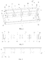
FIG. 3 is a front view of assembly of a battery module and a lower case; -
FIG. 4 is a schematic diagram of installation of a battery module and a lower case; -
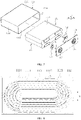
FIG. 5 is a schematic structural diagram of a battery module; -
FIG. 6 is an exploded view of a battery module; -
FIG. 7 is an exploded view of a battery cell; -
FIG. 8 is a cross-sectional view of an electrode assembly in a winding structure; -
FIG. 9 is a cross-sectional view of an electrode assembly in a laminated structure; -
FIG. 10 is a schematic structural diagram of an insulating member; -
FIG. 11 is a schematic structural diagram of an end plate. -
- 1. Battery module,
- 10. Battery cell arrangement structure,
- 11. Battery cell,
- 111. Electrode assembly,
- 1111. First electrode sheet,
- 1112. Second electrode sheet,
- 1113. Diaphragm,
- 1114. Flat surface,
- 112. Battery housing,
- 1121. First surface,
- 1122. Second surface,
- 1123. Internal space,
- 1120. Opening,
- 113. Electrode terminal connector,
- 114. Cover plate,
- 115. Electrode terminal,
- 12. Bus bar,
- 13. Insulating member,
- 131. First face,
- 132. Second face,
- 14. Binding strip,
- 141. Long side,
- 142. Short side,
- 15. End plate,
- 151. Through hole,
- 152. Restraint groove,
- 16. First step
- 2. Upper case cover,
- 3. Lower case,
- 30. Inner bottom face,
- 31. Mounting beam,
- 311. Upper surface,
- 4. Bolt.
- In order to describe in detail the technical content, structural features, achieved objectives and effects of the technical solution, the following detailed description will be given in conjunction with specific embodiments and accompanying drawings.
- In the description of embodiments of the present application, unless otherwise specified and limited explicitly, the terms "first" and "second" are merely intended for a purpose of description, and shall not be understood as an indication or implication of relative importance. Unless otherwise specified or illustrated, the term "a plurality of' refers to more than two (including two); the terms "connection" and "fixing" should be understood broadly, for example, the "connection" may either be a fixed connection, or a detachable connection, or an integrated connection, or an electrical connection; and the "connection" may either be a direct connection, or an indirect connection through an intermediary. For those of ordinary skill in the art, the specific meanings of the above-mentioned terms in the embodiments of the present application can be understood according to specific circumstances.
- In the description of the embodiments of the present application, a direction indicated by an arrow x in all drawings is a length direction, a direction indicated by an arrow y is a width direction, and a direction indicated by an arrow z is a vertical direction. A horizontal direction is a direction parallel to a horizontal plane, and may either be the above length direction or the above width direction. In addition, the horizontal direction includes not only a direction absolutely parallel to the horizontal plane, but also a direction substantially parallel to the horizontal plane conventionally recognized in engineering. A vertical direction is a direction perpendicular to the horizontal plane, and the vertical direction includes not only a direction absolutely perpendicular to the horizontal plane, but also a direction substantially perpendicular to the horizontal plane conventionally recognized in engineering. In addition, orientation words such as "upper", "lower", "top" and "bottom" described in the present application are all understood with respect to the vertical direction.
- When battery cells usually need to be used in groups, it is necessary to use a bus bar to connect each battery cell in series or in parallel. A plurality of battery cells are grouped to form a battery module. A plurality of battery modules are packaged by a case to form a battery pack. However, in the prior art, when a battery module is placed into a case, a surface insulating layer of the battery module is easily pierced due to the presence of a metal burr at the corner of a side wall and a bottom of the case, thereby causing safety accidents.
- On the basis of this, referring to
FIG. 1 , an embodiment relates to a battery pack including a case and a plurality ofbattery modules 1. The case includes anupper case cover 2 and alower case 3, theupper case cover 2 is located above thelower case 3, and theupper case cover 2 is disposed to be sealed with thelower case 3. The sealing setting of theupper case cover 2 and thelower case 3 can prevent external moisture from entering the interior of the battery pack and causing short circuits. The battery pack can be configured to be directly mounted on a vehicle to provide a power source for the vehicle. - As shown in
FIGS. 2 to 6 , in some embodiments, abattery module 1 includes a batterycell arrangement structure 10, and the batterycell arrangement structure 10 includes a plurality ofbattery cells 11 arranged in a horizontal direction (for example, a length direction indicated by an arrow x) and a plurality ofbus bars 12 electrically connecting the plurality ofbattery cells 11. - Moreover, in some embodiments, the
battery module 1 includes at least two batterycell arrangement structures 10, and the at least two batterycell arrangement structures 10 are arranged in a vertical direction (a direction indicated by an arrow z), that is, the plurality ofbattery cells 11 are also arranged in the vertical direction (the direction indicated by the arrow z). In other embodiments, the number of batterycell arrangement structures 10 may also be one. - In some embodiments, as shown in
FIGS. 2, 3 , and10 , thebattery module 1 further includes insulatingmembers 13. The insulatingmember 13 includes afirst face 131 and asecond face 132, thefirst face 131 is located on a side face of the batterycell arrangement structure 10, thesecond face 132 is located on a bottom face of the batterycell arrangement structure 10, and two sides of the bottom of the batterycell arrangement structure 10 are respectively provided with one insulatingmember 13. A bindingstrip 14 surrounds outer peripheries of anend plate 15, thebattery cell 11 and the insulatingmember 13. The insulatingmember 13 not only plays a role of insulation protection, but also prevents thebattery cell 11 from being locally tightened by the bindingstrip 14 and causing uneven stress. - As shown in
FIGS. 2 and 3 , thebattery module 1 in some embodiments further includes twoend plates 15, the twoend plates 15 are respectively disposed at two ends of the batterycell arrangement structure 10 in a length direction (for example, the direction indicated by the arrow x), theend plates 15 are located above the insulatingmembers 13, and thebinding strip 14 surrounds outer peripheries of the batterycell arrangement structure 10 and the twoend plates 15. - In addition, in some embodiments, as shown in
FIGS. 2, 3, 4 , and11 , theend plate 15 is provided with a throughhole 151 for abolt 4 to pass through, and the throughhole 151 is disposed in the vertical direction (the direction indicated by the arrow z). Thebolt 4 passes through the throughhole 151 to fix thebattery module 1 on a mountingbeam 31 of thelower case 3. Theend plate 15 makes an avoidance at a position close to thelower case 3, and a bottom face of theend plate 15 is higher than the bottom face of the batterycell arrangement structure 10, and the bottom face of theend plate 15 and the bottom face of the batterycell arrangement structure 10 form afirst step 16. Anupper surface 311 of the mountingbeam 31 and aninner bottom face 30 of thelower case 3 form a second step, the second step is adapted to thefirst step 16, and thebolt 4 passes through the throughhole 151 to fix theend plate 15 on the mountingbeam 31. In addition, alower surface 312 of the mountingbeam 31 is prone to cut a surface insulating layer of thebattery cell 11. Therefore, the insulatingmember 13 is disposed on the side of the mountingbeam 31 for protection and at the same time can prevent the surface insulating layer of thebattery module 1 from being pierced by a metal burr of thelower case 3. - As shown in
FIGS. 5, 6 , and7 , thebattery module 1 further includes abinding strip 14, and thebinding strip 14 surrounds the outer periphery of the batterycell arrangement structure 10. The bindingstrip 14 includes twolong sides 141 and twoshort sides 142, thelong side 141 faces afirst surface 1121 of thebattery cell 11 and extends in the horizontal direction (for example, the direction indicated by the arrow x), and theshort side 142 faces asecond surface 1122 of thebattery cell 11 and extends in the vertical direction (the direction indicated by the arrow z). In other embodiments, thebattery module 1 may be fixed by means of a press bar, a side plate or a bolt. - In some embodiments, the outer periphery of the battery
cell arrangement structure 10 may be surrounded by the bindingstrip 14, so as to achieve fixing of the batterycell arrangement structure 10, which is more lightweight than that obtained in other methods. - The
battery module 1 is provided with at least twobinding strips 14, such as two or three binding strips. The twobinding strips 14 are distributed at intervals in a width direction (for example, a direction indicated by an arrow y). In some embodiments, the number of the bindingstrips 14 may be one. - As shown in
FIGS. 7 to 9 , thebattery cell 11 includes anelectrode assembly 111, abattery housing 112, anelectrode terminal connector 113, and acover plate 114. Thebattery housing 112 may have a hexahedral shape or other shapes. Thebattery housing 112 has aninternal space 1123 accommodating theelectrode assembly 111 and an electrolyte, and thebattery housing 112 has anopening 1120. Theelectrode assembly 111 is accommodated in thebattery housing 112, thecover plate 114 covers theopening 1120 and is configured to seal theelectrode assembly 111 in thebattery housing 112, and theelectrode assembly 111 and anelectrode terminal 115 are electrically connected through theelectrode terminal connector 113. In this embodiment, there are twoelectrode terminal connectors 113, that is, a positiveelectrode terminal connector 113 and a negativeelectrode terminal connector 113, respectively. Thebattery housing 112 may be made of a material such as aluminum, aluminum alloy, or plastic. - As shown in
FIGS. 8 and9 , theelectrode assembly 111 is accommodated in thebattery housing 112. Onebattery cell 11 includes a plurality ofelectrode assemblies 111, and the plurality ofelectrode assemblies 111 are arranged in the vertical direction (the direction indicated by the arrow z). Theelectrode assembly 111 includes afirst electrode sheet 1111, asecond electrode sheet 1112, and adiaphragm 1113 disposed between thefirst electrode sheet 1111 and thesecond electrode sheet 1112. Thefirst electrode sheet 1111 may be a positive electrode sheet or a negative electrode sheet, and thesecond electrode sheet 1112 and thefirst electrode sheet 1111 have opposite polarities. Accordingly, thesecond electrode sheet 1112 is a negative electrode sheet or a positive electrode sheet. Thediaphragm 1113 is an insulator between thefirst electrode sheet 1111 and thesecond electrode sheet 1112. Theelectrode assembly 111 may be in a winding structure (as shown inFIG. 8 ) or a laminated structure (as shown inFIG. 9 ). - Illustratively, description is made by an example that the
first electrode sheet 1111 is a positive electrode sheet, and thesecond electrode sheet 1112 is a negative electrode sheet. Similarly, in other embodiments, thefirst electrode sheet 1111 may also be a negative electrode sheet, and thesecond electrode sheet 1112 is a positive electrode sheet. In addition, a positive electrode active material is coated on a coated region of a positive electrode sheet, and a negative electrode active material is coated on a coated region of a negative electrode sheet. An uncoated region extending from the coated region is used as an electrode tab. Theelectrode assembly 111 includes two electrode tabs, that is, a positive electrode tab and a negative electrode tab. The positive electrode tab extends from the coated region of the positive electrode sheet; and the negative electrode tab extends from the coated region of the negative electrode sheet. The positive electrode tab and a positive electrode terminal are electrically connected by a positive electrode connector, and the negative electrode tab and a negative electrode terminal are electrically connected by a negative electrode connector. - As shown in
FIG. 7 , thebattery housing 112 is in a substantially hexahedral structure. Thebattery housing 112 includes twofirst surfaces 1121 and twosecond surfaces 1122. The area of thefirst surface 1121 is larger than the area of thesecond surface 1122. In afirst battery module 1 and asecond battery module 1, twosecond surfaces 1122 of eachbattery cell 11 face each other in the horizontal direction (for example, the length direction of the direction indicated by the arrow x), and twofirst surfaces 1121 of eachbattery cell 11 face each other in the vertical direction (the direction indicated by the arrow z). - As shown in
FIGS. 7 and 8 , when theelectrode assembly 111 is in a winding structure, theelectrode assembly 111 is flat-shaped, and an outer surface of theelectrode assembly 111 includes twoflat surfaces 1114. The twoflat surfaces 1114 face each other in the vertical direction (the direction indicated by the arrow z), that is, theflat surface 1114 and thefirst surface 1121 face each other. Theelectrode assembly 111 is in a substantially hexahedral structure, and theflat surface 1114 is substantially parallel to a winding axis and is an outer surface with the largest area. Theflat surface 1114 may be a relatively even surface, and is not required to be a pure plane. - As shown in
FIG. 9 , when theelectrode assembly 111 is in a laminated structure, afirst electrode sheet 1111, adiaphragm 1113, and asecond electrode sheet 1112 are stacked in the vertical direction (the direction indicated by the arrow z), that is, a surface of thefirst electrode sheet 1111 and thefirst surface 1121 face each other. - The
electrode assembly 111 will inevitably expand in a thickness direction of thefirst electrode sheet 1111 during a charging and discharging process (in theelectrode assembly 111 with the winding structure, an expansion force in a direction perpendicular to theflat surface 1114 is the maximum; and in theelectrode assembly 111 with the laminated structure, an expansion force in an arrangement direction of thefirst electrode sheet 1111 and thesecond electrode sheet 1112 is the maximum). - In addition, in some embodiments, the
electrode assembly 111 may adopt a winding structure or a laminated structure. As shown inFIG. 8 , when theelectrode assembly 111 is in a winding structure, theflat surface 1114 faces toward the vertical direction (the direction indicated by the arrow z). As shown inFIG. 9 , when theelectrode assembly 111 is in a laminated structure, thefirst electrode sheet 1111 and thesecond electrode sheet 1112 are stacked in the vertical direction (the direction indicated by the arrow z). It can be seen that no matter whether theelectrode assembly 111 adopts a winding structure or a laminated structure, a direction in which theelectrode assembly 111 exerts the maximum expansion force on thebattery housing 112 is toward the vertical direction. - In the prior art, in a
battery cell 11 of abattery module 1, a direction in which anelectrode assembly 111 exerts the maximum expansion force on abattery housing 112 is toward a horizontal direction. Since the size of thebattery module 1 in a horizontal direction is much larger than the size thereof in a vertical direction (for example, due to limitation of the height of a vehicle chassis,more battery cells 11 are required to be arranged in the horizontal direction, and the accumulated expansion force is large), the existingbattery module 1 suffers from an extremely large expansion force in the horizontal direction, and it is necessary to provide very thick end plates on two sides of thebattery module 1 in the horizontal direction to resist the expansion force. However, the thicker end plates will reduce energy density of thebattery module 1. In this embodiment, a direction in which theelectrode assembly 111 exerts the maximum expansion force on thebattery housing 112 is toward the vertical direction, and the number ofbattery cells 11 arranged in the vertical direction is smaller. Therefore, compared with the prior art, the maximum expansion force of thebattery module 1 can be significantly reduced. - In addition, as shown in
FIG. 7 , since thebattery cell 11 generates gas inside thebattery housing 112 during the charging and discharging process, the generated gas will exert a force on thebattery housing 112, thereby increasing the outward expansion of thebattery housing 112. Since the area of thefirst surface 1121 is larger than the area of thesecond surface 1122, and the twofirst surfaces 1121 in thebattery cell 11 face each other in the vertical direction, a direction of the maximum force exerted by the generated gas on thebattery housing 112 is also toward the vertical direction. Compared with the prior art, the maximum expansion force of thebattery module 1 is further reduced. - As shown in
FIGS. 6 ,7 , and10 , the insulatingmember 13 includes afirst face 131 and asecond face 132, thefirst face 131 is located on a side face of the batterycell arrangement structure 10, and thesecond face 132 is located on a bottom face of the batterycell arrangement structure 10. Thefirst face 131 is used to abut against the side face (the second surface 1122) of thebattery cell 11, and thesecond face 132 is used to abut against the bottom face (the first surface 1121) of thebattery cell 11. The abutment described herein may be a direct abutment, or an indirect abutment through other parts (for example, through an insulating layer on the surface of the battery cell 11). - As shown in
FIG. 11 , theend plate 15 in some embodiments of the present application is provided with a throughhole 151 for abolt 4 to pass through, and the throughhole 151 is disposed in a vertical direction. Theend plate 15 is also provided with a bindingstrip restraint groove 152, and the bindingstrip restraint groove 152 is configured to restrain thebinding strip 14. Alternatively, theend plate 15 is provided with a binding strip restraint hole in a vertical direction, which can also restrain thebinding strip 14. - During an assembly process, as shown in
FIG. 2 , a mountingbeam 31 is mounted at the bottom of alower case 3; a plurality ofbattery cells 11 are arranged in a horizontal direction (for example, a direction indicated by an arrow x) and a vertical direction (a direction indicated by an arrow z); two insulatingmembers 13 are disposed on two sides of the bottom of the plurality ofbattery cells 11; the plurality ofbattery cells 11 and the insulatingmembers 13 are fixed through anend plate 15 and abinding strip 14 to form abattery module 1; abolt 4 passes through a throughhole 151 on theend plate 15 to fix thebattery module 1 on the mountingbeam 31; and acase cover 2 is covered to complete the assembly of a battery pack.
Claims (12)
- Battery module, comprising:a plurality of battery cells (11), the plurality of battery cells (11) being arranged in a horizontal direction;two insulating members (13), the insulating member (13) comprising a first face (131) and a second face (132), the first face (131) being located on a side face of the battery module, the second face (132) being located on a bottom face of the battery module, and the two insulating members (13) being respectively disposed on two sides of the battery module in the horizontal direction; anda binding strip (14), the binding strip (14) surrounding the plurality of battery cells (11) and the insulating members;wherein the battery module further comprises two end plates (15), the two end plates (15) are respectively disposed at two ends of the plurality of battery cells (11) in the horizontal direction, the end plates (15) are located above the insulating members (13), and the binding strip (14) surrounds the plurality of battery cells (11), the two insulating members (13) and the two end plates (15);wherein the end plate (15) is provided with a binding strip restraint groove (152) or a binding strip restraint hole and;wherein the battery cell (11) comprises an electrode assembly (111) and a battery housing (112), the electrode assembly (111) is accommodated in the battery housing (112), and the electrode assembly (111) comprises a first electrode sheet (1111), a second electrode sheet (1112), and a diaphragm (1113) disposed between the first electrode sheet (1111) and the second electrode sheet (1112); andthe electrode assembly (111) is in a winding structure and is flat-shaped, an outer surface of the electrode assembly (111) comprises two flat surfaces (1114), and the two flat surfaces (1114) face each other in a vertical direction; or, the electrode assembly (111) is in a laminated structure, and the first electrode sheet (1111), the diaphragm (1113), and the second electrode sheet (1112) are stacked in the vertical direction.
- Battery module according to claim 1, wherein the end plate (15) is provided with a through hole (151) for a bolt (4) to pass through, and the through hole (151) is disposed in a vertical direction.
- Battery module according to claim 1 or 2, wherein the binding strip (14) comprises a long side (141) and a short side (142), the long side (141) extends in the horizontal direction, the short side (142) extends in a vertical direction, and the binding strip (14) surrounds outer peripheries of the plurality of battery cells (11) and the two insulating members (13).
- Battery module according to claim 3, wherein the battery cell (11) comprises a plurality of electrode assemblies (111), and the plurality of electrode assemblies (111) are arranged in a vertical direction.
- Battery module according to any one of claims 1-4, wherein the plurality of battery cells (11) are also arranged in a vertical direction.
- Battery module according to any one of claims 1-4, wherein the battery module further comprises a plurality of battery cells (11) arranged in a vertical direction.
- Battery module according to any one of claims 1-6, the battery module is provided with at least two binding strips (14).
- Battery pack, comprising:a case, the case comprising an upper case cover (2) and a lower case (3), and the upper case cover (2) being located above the lower case (3) and disposed to be sealed with the lower case (3); andthe battery module (1) according to any one of claims 1-7 disposed in the case.
- Battery pack according to claim 8, wherein a mounting beam (31) is disposed at the bottom of the lower case (3), and the insulating member (13) is disposed above the mounting beam (31).
- Battery pack according to claim 8 or 9, wherein a bottom face of the end plate (15) is higher than the bottom face of the plurality of battery cells (11), and the bottom face of the end plate (15) and the bottom face of the plurality of battery cells (11) form a first step (16).
- Battery pack according to claim 10, wherein an upper surface (311) of the mounting beam (31) and an inner bottom face (30) of the lower case (3) form a second step, the second step is adapted to the first step (16), and the bolt (4) passes through the through hole (151) to fix the end plate (15) on the mounting beam (31).
- Vehicle, comprising:the battery pack according to any one of claims 8-11,wherein the battery pack is configured to be mounted on the a vehicle to provide a power source for the vehicle.
Applications Claiming Priority (2)
| Application Number | Priority Date | Filing Date | Title |
|---|---|---|---|
| CN201822275004.7U CN209249577U (en) | 2018-12-30 | 2018-12-30 | A battery module and battery pack |
| PCT/CN2019/121031 WO2020140653A1 (en) | 2018-12-30 | 2019-11-26 | Battery module and battery pack |
Publications (3)
| Publication Number | Publication Date |
|---|---|
| EP3800704A1 EP3800704A1 (en) | 2021-04-07 |
| EP3800704A4 EP3800704A4 (en) | 2021-10-13 |
| EP3800704B1 true EP3800704B1 (en) | 2022-04-20 |
Family
ID=67535824
Family Applications (1)
| Application Number | Title | Priority Date | Filing Date |
|---|---|---|---|
| EP19907322.2A Active EP3800704B1 (en) | 2018-12-30 | 2019-11-26 | Battery module and battery pack |
Country Status (4)
| Country | Link |
|---|---|
| US (1) | US12300828B2 (en) |
| EP (1) | EP3800704B1 (en) |
| CN (1) | CN209249577U (en) |
| WO (1) | WO2020140653A1 (en) |
Families Citing this family (8)
| Publication number | Priority date | Publication date | Assignee | Title |
|---|---|---|---|---|
| CN209249577U (en) * | 2018-12-30 | 2019-08-13 | 宁德时代新能源科技股份有限公司 | A battery module and battery pack |
| CN211017198U (en) * | 2019-12-31 | 2020-07-14 | 宁德时代新能源科技股份有限公司 | Battery module, battery pack and device |
| JP7433305B2 (en) * | 2020-07-17 | 2024-02-19 | 東莞新能安科技有限公司 | battery module |
| WO2022036531A1 (en) | 2020-08-17 | 2022-02-24 | 宁德时代新能源科技股份有限公司 | Battery cell, battery, and method and apparatus for preparing battery cell |
| CN116325311B (en) * | 2022-01-13 | 2025-07-29 | 宁德时代新能源科技股份有限公司 | Battery module, battery, consumer, method and device for producing a battery |
| CN116666883A (en) * | 2023-06-26 | 2023-08-29 | 厦门海辰储能科技股份有限公司 | Battery pack and power consumption system |
| JP2025537453A (en) * | 2023-10-12 | 2025-11-18 | 恵州億緯▲リ▼能股▲フン▼有限公司 | Battery module |
| CN117175125A (en) * | 2023-10-12 | 2023-12-05 | 惠州亿纬锂能股份有限公司 | battery module |
Family Cites Families (14)
| Publication number | Priority date | Publication date | Assignee | Title |
|---|---|---|---|---|
| US4020244A (en) * | 1975-02-18 | 1977-04-26 | Motorola, Inc. | Clamping structure for battery cells |
| US7129001B2 (en) * | 2001-12-18 | 2006-10-31 | Gs Yuasa Corporation | Cell comprising a power-generating element fastened by sheets |
| WO2010131700A1 (en) * | 2009-05-14 | 2010-11-18 | 株式会社Gsユアサ | Battery assembly |
| EP2325922B1 (en) | 2009-11-19 | 2012-05-09 | SB LiMotive Co., Ltd. | Battery pack |
| US20120114984A1 (en) * | 2010-11-04 | 2012-05-10 | Myung-Chul Kim | Battery module |
| CN201893394U (en) * | 2010-11-09 | 2011-07-06 | 上海比亚迪有限公司 | Novel automobile battery pack |
| KR20140025132A (en) * | 2012-08-21 | 2014-03-04 | 삼성에스디아이 주식회사 | Battery pack |
| KR102468334B1 (en) * | 2015-11-04 | 2022-11-16 | 삼성에스디아이 주식회사 | Rechargeable battery module |
| KR102235655B1 (en) * | 2016-06-17 | 2021-04-01 | 에스케이이노베이션 주식회사 | Secondary battery pack |
| CN207441810U (en) * | 2017-11-15 | 2018-06-01 | 宁德时代新能源科技股份有限公司 | Battery modules and battery pack |
| CN208028109U (en) * | 2018-02-24 | 2018-10-30 | 宿迁杉杉运通新能源系统有限公司 | A kind of bundling type battery modules |
| CN208111582U (en) * | 2018-03-15 | 2018-11-16 | 合肥国轩高科动力能源有限公司 | A fully protected battery module structure |
| CN111384334B (en) | 2018-12-30 | 2024-09-13 | 宁德时代新能源科技股份有限公司 | Battery pack |
| CN209249577U (en) * | 2018-12-30 | 2019-08-13 | 宁德时代新能源科技股份有限公司 | A battery module and battery pack |
-
2018
- 2018-12-30 CN CN201822275004.7U patent/CN209249577U/en active Active
-
2019
- 2019-11-26 EP EP19907322.2A patent/EP3800704B1/en active Active
- 2019-11-26 WO PCT/CN2019/121031 patent/WO2020140653A1/en not_active Ceased
-
2020
- 2020-12-31 US US17/139,830 patent/US12300828B2/en active Active
Also Published As
| Publication number | Publication date |
|---|---|
| US12300828B2 (en) | 2025-05-13 |
| EP3800704A4 (en) | 2021-10-13 |
| US20210126310A1 (en) | 2021-04-29 |
| WO2020140653A1 (en) | 2020-07-09 |
| CN209249577U (en) | 2019-08-13 |
| EP3800704A1 (en) | 2021-04-07 |
Similar Documents
| Publication | Publication Date | Title |
|---|---|---|
| EP3800704B1 (en) | Battery module and battery pack | |
| EP3525255B1 (en) | Battery module | |
| US11289762B2 (en) | Battery pack | |
| US11251487B2 (en) | Battery module and battery pack | |
| EP3151307B1 (en) | Battery module and battery pack comprising same | |
| EP3678208A1 (en) | Battery module, battery pack, and vehicle | |
| EP3758091A1 (en) | Battery pack and vehicle | |
| JP2023526640A (en) | Large battery modules and battery packs containing them | |
| JP7186926B2 (en) | Battery modules, battery packs and devices using batteries as power sources | |
| KR102835864B1 (en) | Top cover assembly, secondary battery, battery module and device | |
| KR20220084357A (en) | Secondary batteries, battery modules, and devices using batteries as power | |
| JP2022550613A (en) | SECONDARY BATTERY, BATTERY MODULE, BATTERY PACK, APPARATUS AND MANUFACTURING METHOD | |
| EP3930025B1 (en) | Battery module, battery pack, and vehicle | |
| CN113328194B (en) | Battery, battery module, battery pack and electric vehicle | |
| EP3790080B1 (en) | Battery module and battery pack | |
| US11101521B2 (en) | Battery module and battery pack | |
| EP4109649B1 (en) | Battery module and battery pack including the same | |
| JP2008108651A (en) | Battery pack and manufacturing method thereof | |
| KR102895043B1 (en) | Connection wire and battery pack including the same | |
| KR20250103694A (en) | Battery mounting devices, batteries and electrical appliances | |
| KR101443833B1 (en) | External Input and Output Cable Assembly with Novel Structure, and Battery Module Assembly Employed with the Same | |
| JP2023509736A (en) | BATTERY MODULE, BATTERY PACK INCLUDING THE SAME AND MANUFACTURING METHOD THEREOF | |
| KR102767703B1 (en) | Battery pack and device including the same | |
| KR102754510B1 (en) | Battery pack and device including the same | |
| CN222233753U (en) | Battery pack and electric vehicle |
Legal Events
| Date | Code | Title | Description |
|---|---|---|---|
| STAA | Information on the status of an ep patent application or granted ep patent |
Free format text: STATUS: THE INTERNATIONAL PUBLICATION HAS BEEN MADE |
|
| PUAI | Public reference made under article 153(3) epc to a published international application that has entered the european phase |
Free format text: ORIGINAL CODE: 0009012 |
|
| STAA | Information on the status of an ep patent application or granted ep patent |
Free format text: STATUS: REQUEST FOR EXAMINATION WAS MADE |
|
| 17P | Request for examination filed |
Effective date: 20201230 |
|
| AK | Designated contracting states |
Kind code of ref document: A1 Designated state(s): AL AT BE BG CH CY CZ DE DK EE ES FI FR GB GR HR HU IE IS IT LI LT LU LV MC MK MT NL NO PL PT RO RS SE SI SK SM TR |
|
| AX | Request for extension of the european patent |
Extension state: BA ME |
|
| REG | Reference to a national code |
Ref country code: DE Ref legal event code: R079 Ref document number: 602019013985 Country of ref document: DE Free format text: PREVIOUS MAIN CLASS: H01M0002340000 Ipc: H01M0050209000 |
|
| A4 | Supplementary search report drawn up and despatched |
Effective date: 20210913 |
|
| RIC1 | Information provided on ipc code assigned before grant |
Ipc: H01M 50/533 20210101ALI20210907BHEP Ipc: H01M 50/249 20210101ALI20210907BHEP Ipc: H01M 50/264 20210101ALI20210907BHEP Ipc: H01M 50/242 20210101ALI20210907BHEP Ipc: H01M 50/209 20210101AFI20210907BHEP |
|
| GRAP | Despatch of communication of intention to grant a patent |
Free format text: ORIGINAL CODE: EPIDOSNIGR1 |
|
| STAA | Information on the status of an ep patent application or granted ep patent |
Free format text: STATUS: GRANT OF PATENT IS INTENDED |
|
| INTG | Intention to grant announced |
Effective date: 20220201 |
|
| GRAS | Grant fee paid |
Free format text: ORIGINAL CODE: EPIDOSNIGR3 |
|
| GRAA | (expected) grant |
Free format text: ORIGINAL CODE: 0009210 |
|
| STAA | Information on the status of an ep patent application or granted ep patent |
Free format text: STATUS: THE PATENT HAS BEEN GRANTED |
|
| DAV | Request for validation of the european patent (deleted) | ||
| DAX | Request for extension of the european patent (deleted) | ||
| AK | Designated contracting states |
Kind code of ref document: B1 Designated state(s): AL AT BE BG CH CY CZ DE DK EE ES FI FR GB GR HR HU IE IS IT LI LT LU LV MC MK MT NL NO PL PT RO RS SE SI SK SM TR |
|
| REG | Reference to a national code |
Ref country code: GB Ref legal event code: FG4D |
|
| REG | Reference to a national code |
Ref country code: CH Ref legal event code: EP |
|
| REG | Reference to a national code |
Ref country code: DE Ref legal event code: R096 Ref document number: 602019013985 Country of ref document: DE |
|
| REG | Reference to a national code |
Ref country code: IE Ref legal event code: FG4D |
|
| REG | Reference to a national code |
Ref country code: AT Ref legal event code: REF Ref document number: 1485919 Country of ref document: AT Kind code of ref document: T Effective date: 20220515 |
|
| REG | Reference to a national code |
Ref country code: SE Ref legal event code: TRGR |
|
| REG | Reference to a national code |
Ref country code: LT Ref legal event code: MG9D |
|
| REG | Reference to a national code |
Ref country code: NL Ref legal event code: MP Effective date: 20220420 |
|
| PG25 | Lapsed in a contracting state [announced via postgrant information from national office to epo] |
Ref country code: NL Free format text: LAPSE BECAUSE OF FAILURE TO SUBMIT A TRANSLATION OF THE DESCRIPTION OR TO PAY THE FEE WITHIN THE PRESCRIBED TIME-LIMIT Effective date: 20220420 |
|
| PG25 | Lapsed in a contracting state [announced via postgrant information from national office to epo] |
Ref country code: PT Free format text: LAPSE BECAUSE OF FAILURE TO SUBMIT A TRANSLATION OF THE DESCRIPTION OR TO PAY THE FEE WITHIN THE PRESCRIBED TIME-LIMIT Effective date: 20220822 Ref country code: NO Free format text: LAPSE BECAUSE OF FAILURE TO SUBMIT A TRANSLATION OF THE DESCRIPTION OR TO PAY THE FEE WITHIN THE PRESCRIBED TIME-LIMIT Effective date: 20220720 Ref country code: LT Free format text: LAPSE BECAUSE OF FAILURE TO SUBMIT A TRANSLATION OF THE DESCRIPTION OR TO PAY THE FEE WITHIN THE PRESCRIBED TIME-LIMIT Effective date: 20220420 Ref country code: HR Free format text: LAPSE BECAUSE OF FAILURE TO SUBMIT A TRANSLATION OF THE DESCRIPTION OR TO PAY THE FEE WITHIN THE PRESCRIBED TIME-LIMIT Effective date: 20220420 Ref country code: GR Free format text: LAPSE BECAUSE OF FAILURE TO SUBMIT A TRANSLATION OF THE DESCRIPTION OR TO PAY THE FEE WITHIN THE PRESCRIBED TIME-LIMIT Effective date: 20220721 Ref country code: FI Free format text: LAPSE BECAUSE OF FAILURE TO SUBMIT A TRANSLATION OF THE DESCRIPTION OR TO PAY THE FEE WITHIN THE PRESCRIBED TIME-LIMIT Effective date: 20220420 Ref country code: ES Free format text: LAPSE BECAUSE OF FAILURE TO SUBMIT A TRANSLATION OF THE DESCRIPTION OR TO PAY THE FEE WITHIN THE PRESCRIBED TIME-LIMIT Effective date: 20220420 Ref country code: BG Free format text: LAPSE BECAUSE OF FAILURE TO SUBMIT A TRANSLATION OF THE DESCRIPTION OR TO PAY THE FEE WITHIN THE PRESCRIBED TIME-LIMIT Effective date: 20220720 |
|
| PG25 | Lapsed in a contracting state [announced via postgrant information from national office to epo] |
Ref country code: RS Free format text: LAPSE BECAUSE OF FAILURE TO SUBMIT A TRANSLATION OF THE DESCRIPTION OR TO PAY THE FEE WITHIN THE PRESCRIBED TIME-LIMIT Effective date: 20220420 Ref country code: PL Free format text: LAPSE BECAUSE OF FAILURE TO SUBMIT A TRANSLATION OF THE DESCRIPTION OR TO PAY THE FEE WITHIN THE PRESCRIBED TIME-LIMIT Effective date: 20220420 Ref country code: LV Free format text: LAPSE BECAUSE OF FAILURE TO SUBMIT A TRANSLATION OF THE DESCRIPTION OR TO PAY THE FEE WITHIN THE PRESCRIBED TIME-LIMIT Effective date: 20220420 Ref country code: IS Free format text: LAPSE BECAUSE OF FAILURE TO SUBMIT A TRANSLATION OF THE DESCRIPTION OR TO PAY THE FEE WITHIN THE PRESCRIBED TIME-LIMIT Effective date: 20220820 |
|
| REG | Reference to a national code |
Ref country code: DE Ref legal event code: R097 Ref document number: 602019013985 Country of ref document: DE |
|
| PG25 | Lapsed in a contracting state [announced via postgrant information from national office to epo] |
Ref country code: SM Free format text: LAPSE BECAUSE OF FAILURE TO SUBMIT A TRANSLATION OF THE DESCRIPTION OR TO PAY THE FEE WITHIN THE PRESCRIBED TIME-LIMIT Effective date: 20220420 Ref country code: SK Free format text: LAPSE BECAUSE OF FAILURE TO SUBMIT A TRANSLATION OF THE DESCRIPTION OR TO PAY THE FEE WITHIN THE PRESCRIBED TIME-LIMIT Effective date: 20220420 Ref country code: RO Free format text: LAPSE BECAUSE OF FAILURE TO SUBMIT A TRANSLATION OF THE DESCRIPTION OR TO PAY THE FEE WITHIN THE PRESCRIBED TIME-LIMIT Effective date: 20220420 Ref country code: EE Free format text: LAPSE BECAUSE OF FAILURE TO SUBMIT A TRANSLATION OF THE DESCRIPTION OR TO PAY THE FEE WITHIN THE PRESCRIBED TIME-LIMIT Effective date: 20220420 Ref country code: DK Free format text: LAPSE BECAUSE OF FAILURE TO SUBMIT A TRANSLATION OF THE DESCRIPTION OR TO PAY THE FEE WITHIN THE PRESCRIBED TIME-LIMIT Effective date: 20220420 Ref country code: CZ Free format text: LAPSE BECAUSE OF FAILURE TO SUBMIT A TRANSLATION OF THE DESCRIPTION OR TO PAY THE FEE WITHIN THE PRESCRIBED TIME-LIMIT Effective date: 20220420 |
|
| PLBE | No opposition filed within time limit |
Free format text: ORIGINAL CODE: 0009261 |
|
| STAA | Information on the status of an ep patent application or granted ep patent |
Free format text: STATUS: NO OPPOSITION FILED WITHIN TIME LIMIT |
|
| 26N | No opposition filed |
Effective date: 20230123 |
|
| PG25 | Lapsed in a contracting state [announced via postgrant information from national office to epo] |
Ref country code: AL Free format text: LAPSE BECAUSE OF FAILURE TO SUBMIT A TRANSLATION OF THE DESCRIPTION OR TO PAY THE FEE WITHIN THE PRESCRIBED TIME-LIMIT Effective date: 20220420 |
|
| PG25 | Lapsed in a contracting state [announced via postgrant information from national office to epo] |
Ref country code: SI Free format text: LAPSE BECAUSE OF FAILURE TO SUBMIT A TRANSLATION OF THE DESCRIPTION OR TO PAY THE FEE WITHIN THE PRESCRIBED TIME-LIMIT Effective date: 20220420 |
|
| P01 | Opt-out of the competence of the unified patent court (upc) registered |
Effective date: 20230516 |
|
| PG25 | Lapsed in a contracting state [announced via postgrant information from national office to epo] |
Ref country code: MC Free format text: LAPSE BECAUSE OF FAILURE TO SUBMIT A TRANSLATION OF THE DESCRIPTION OR TO PAY THE FEE WITHIN THE PRESCRIBED TIME-LIMIT Effective date: 20220420 |
|
| REG | Reference to a national code |
Ref country code: CH Ref legal event code: PL |
|
| REG | Reference to a national code |
Ref country code: BE Ref legal event code: MM Effective date: 20221130 |
|
| PG25 | Lapsed in a contracting state [announced via postgrant information from national office to epo] |
Ref country code: LI Free format text: LAPSE BECAUSE OF NON-PAYMENT OF DUE FEES Effective date: 20221130 Ref country code: CH Free format text: LAPSE BECAUSE OF NON-PAYMENT OF DUE FEES Effective date: 20221130 |
|
| REG | Reference to a national code |
Ref country code: AT Ref legal event code: UEP Ref document number: 1485919 Country of ref document: AT Kind code of ref document: T Effective date: 20220420 |
|
| PG25 | Lapsed in a contracting state [announced via postgrant information from national office to epo] |
Ref country code: LU Free format text: LAPSE BECAUSE OF NON-PAYMENT OF DUE FEES Effective date: 20221126 |
|
| PG25 | Lapsed in a contracting state [announced via postgrant information from national office to epo] |
Ref country code: IE Free format text: LAPSE BECAUSE OF NON-PAYMENT OF DUE FEES Effective date: 20221126 |
|
| PG25 | Lapsed in a contracting state [announced via postgrant information from national office to epo] |
Ref country code: BE Free format text: LAPSE BECAUSE OF NON-PAYMENT OF DUE FEES Effective date: 20221130 |
|
| PG25 | Lapsed in a contracting state [announced via postgrant information from national office to epo] |
Ref country code: CY Free format text: LAPSE BECAUSE OF FAILURE TO SUBMIT A TRANSLATION OF THE DESCRIPTION OR TO PAY THE FEE WITHIN THE PRESCRIBED TIME-LIMIT Effective date: 20220420 |
|
| PG25 | Lapsed in a contracting state [announced via postgrant information from national office to epo] |
Ref country code: MK Free format text: LAPSE BECAUSE OF FAILURE TO SUBMIT A TRANSLATION OF THE DESCRIPTION OR TO PAY THE FEE WITHIN THE PRESCRIBED TIME-LIMIT Effective date: 20220420 Ref country code: HU Free format text: LAPSE BECAUSE OF FAILURE TO SUBMIT A TRANSLATION OF THE DESCRIPTION OR TO PAY THE FEE WITHIN THE PRESCRIBED TIME-LIMIT; INVALID AB INITIO Effective date: 20191126 |
|
| PG25 | Lapsed in a contracting state [announced via postgrant information from national office to epo] |
Ref country code: TR Free format text: LAPSE BECAUSE OF FAILURE TO SUBMIT A TRANSLATION OF THE DESCRIPTION OR TO PAY THE FEE WITHIN THE PRESCRIBED TIME-LIMIT Effective date: 20220420 |
|
| REG | Reference to a national code |
Ref country code: DE Ref legal event code: R081 Ref document number: 602019013985 Country of ref document: DE Owner name: CONTEMPORARY AMPEREX TECHNOLOGY (HONG KONG) LI, HK Free format text: FORMER OWNER: CONTEMPORARY AMPEREX TECHNOLOGY CO., LIMITED, NINGDE CITY, FUJIAN, CN |
|
| REG | Reference to a national code |
Ref country code: GB Ref legal event code: 732E Free format text: REGISTERED BETWEEN 20240815 AND 20240821 |
|
| PG25 | Lapsed in a contracting state [announced via postgrant information from national office to epo] |
Ref country code: MT Free format text: LAPSE BECAUSE OF FAILURE TO SUBMIT A TRANSLATION OF THE DESCRIPTION OR TO PAY THE FEE WITHIN THE PRESCRIBED TIME-LIMIT Effective date: 20220420 |
|
| PG25 | Lapsed in a contracting state [announced via postgrant information from national office to epo] |
Ref country code: BG Free format text: LAPSE BECAUSE OF FAILURE TO SUBMIT A TRANSLATION OF THE DESCRIPTION OR TO PAY THE FEE WITHIN THE PRESCRIBED TIME-LIMIT Effective date: 20220420 |
|
| REG | Reference to a national code |
Ref country code: AT Ref legal event code: PC Ref document number: 1485919 Country of ref document: AT Kind code of ref document: T Owner name: CONTEMPORARY AMPEREX TECHNOLOGY (HONG KONG) LI, HK Effective date: 20240923 |
|
| PG25 | Lapsed in a contracting state [announced via postgrant information from national office to epo] |
Ref country code: BG Free format text: LAPSE BECAUSE OF FAILURE TO SUBMIT A TRANSLATION OF THE DESCRIPTION OR TO PAY THE FEE WITHIN THE PRESCRIBED TIME-LIMIT Effective date: 20220420 |
|
| PGFP | Annual fee paid to national office [announced via postgrant information from national office to epo] |
Ref country code: FR Payment date: 20250930 Year of fee payment: 7 |
|
| PGFP | Annual fee paid to national office [announced via postgrant information from national office to epo] |
Ref country code: DE Payment date: 20250930 Year of fee payment: 7 |
|
| PGFP | Annual fee paid to national office [announced via postgrant information from national office to epo] |
Ref country code: GB Payment date: 20251001 Year of fee payment: 7 |
|
| PGFP | Annual fee paid to national office [announced via postgrant information from national office to epo] |
Ref country code: AT Payment date: 20251027 Year of fee payment: 7 |
|
| PGFP | Annual fee paid to national office [announced via postgrant information from national office to epo] |
Ref country code: IT Payment date: 20251022 Year of fee payment: 7 |
|
| PGFP | Annual fee paid to national office [announced via postgrant information from national office to epo] |
Ref country code: SE Payment date: 20251001 Year of fee payment: 7 |