EP3800575A1 - Visual camera-based method for identifying edge of self-shadowing object, device, and vehicle - Google Patents
Visual camera-based method for identifying edge of self-shadowing object, device, and vehicle Download PDFInfo
- Publication number
- EP3800575A1 EP3800575A1 EP19825559.8A EP19825559A EP3800575A1 EP 3800575 A1 EP3800575 A1 EP 3800575A1 EP 19825559 A EP19825559 A EP 19825559A EP 3800575 A1 EP3800575 A1 EP 3800575A1
- Authority
- EP
- European Patent Office
- Prior art keywords
- boundary
- identified
- peripheral
- determining
- segment
- Prior art date
- Legal status (The legal status is an assumption and is not a legal conclusion. Google has not performed a legal analysis and makes no representation as to the accuracy of the status listed.)
- Granted
Links
Images





Classifications
-
- G—PHYSICS
- G06—COMPUTING OR CALCULATING; COUNTING
- G06T—IMAGE DATA PROCESSING OR GENERATION, IN GENERAL
- G06T7/00—Image analysis
- G06T7/10—Segmentation; Edge detection
- G06T7/12—Edge-based segmentation
-
- G—PHYSICS
- G06—COMPUTING OR CALCULATING; COUNTING
- G06F—ELECTRIC DIGITAL DATA PROCESSING
- G06F18/00—Pattern recognition
- G06F18/20—Analysing
- G06F18/24—Classification techniques
-
- G—PHYSICS
- G06—COMPUTING OR CALCULATING; COUNTING
- G06T—IMAGE DATA PROCESSING OR GENERATION, IN GENERAL
- G06T7/00—Image analysis
- G06T7/40—Analysis of texture
- G06T7/41—Analysis of texture based on statistical description of texture
-
- G—PHYSICS
- G06—COMPUTING OR CALCULATING; COUNTING
- G06V—IMAGE OR VIDEO RECOGNITION OR UNDERSTANDING
- G06V10/00—Arrangements for image or video recognition or understanding
- G06V10/20—Image preprocessing
- G06V10/28—Quantising the image, e.g. histogram thresholding for discrimination between background and foreground patterns
-
- G—PHYSICS
- G06—COMPUTING OR CALCULATING; COUNTING
- G06V—IMAGE OR VIDEO RECOGNITION OR UNDERSTANDING
- G06V10/00—Arrangements for image or video recognition or understanding
- G06V10/40—Extraction of image or video features
-
- G—PHYSICS
- G06—COMPUTING OR CALCULATING; COUNTING
- G06V—IMAGE OR VIDEO RECOGNITION OR UNDERSTANDING
- G06V10/00—Arrangements for image or video recognition or understanding
- G06V10/40—Extraction of image or video features
- G06V10/48—Extraction of image or video features by mapping characteristic values of the pattern into a parameter space, e.g. Hough transformation
-
- G—PHYSICS
- G06—COMPUTING OR CALCULATING; COUNTING
- G06V—IMAGE OR VIDEO RECOGNITION OR UNDERSTANDING
- G06V20/00—Scenes; Scene-specific elements
- G06V20/50—Context or environment of the image
- G06V20/56—Context or environment of the image exterior to a vehicle by using sensors mounted on the vehicle
-
- G—PHYSICS
- G06—COMPUTING OR CALCULATING; COUNTING
- G06V—IMAGE OR VIDEO RECOGNITION OR UNDERSTANDING
- G06V20/00—Scenes; Scene-specific elements
- G06V20/50—Context or environment of the image
- G06V20/56—Context or environment of the image exterior to a vehicle by using sensors mounted on the vehicle
- G06V20/58—Recognition of moving objects or obstacles, e.g. vehicles or pedestrians; Recognition of traffic objects, e.g. traffic signs, traffic lights or roads
-
- G—PHYSICS
- G06—COMPUTING OR CALCULATING; COUNTING
- G06T—IMAGE DATA PROCESSING OR GENERATION, IN GENERAL
- G06T2207/00—Indexing scheme for image analysis or image enhancement
- G06T2207/30—Subject of image; Context of image processing
- G06T2207/30248—Vehicle exterior or interior
- G06T2207/30252—Vehicle exterior; Vicinity of vehicle
Definitions
- the present disclosure relates to the technical field of autopilot, and particularly relates to a method and device for edge identification of a self-shadowing object based on a visual camera and a vehicle.
- ADAS Advanced Driver Assistant Systems
- ADAS Advanced Driver Assistant Systems
- some sensors in the ADAS such as the vision camera, have the function of obtaining two-dimensional images, similar to that of the human being, so they can serve as the main sensors in the ADAS in autopilot vehicles.
- the vision camera utilizes the function of image processing to catch the road images during vehicle driving, and assists the driver in accurately identifying the road in the autopilot mode, which is an important research topic in the field of autopilot.
- self-shadowing objects because the shadow self-shielding that they generate under illumination generates boundary that prevent the objects from being identified, and the boundary varies with the direction of the illumination, that is, the boundary moves on the surface of the object, the identification of the boundaries of self-shadowing objects is very difficult.
- the step of, by using the positions of the first boundary and the second boundary, drawing the peripheral boundary of the object to be identified comprises:
- the step of, according to the intersection point and the third angle, determining the peripheral boundary of the object to be identified comprises:
- the step of, according to the intersection point and the third angle, determining the peripheral boundary of the object to be identified comprises:
- the method further comprises:
- the method further comprises:
- the method for edge identification of a self-shadowing object based on a visual camera has the following advantages: by, in a process of travelling of a vehicle, acquiring image data of the object to be identified; performing differentiation processing to the image data, to acquire an image that has been differentiation-processed, and according to a preset threshold, performing three-value processing to the image that has been differentiation-processed, to acquire a three-value image comprising positive-direction boundary pixels and negative-direction boundary pixels; according to the positive-direction boundary pixels and the negative-direction boundary pixels, acquiring a positive-direction straight linear segment and a negative-direction straight linear segment that represent boundary trends of the object to be identified; if the straight linear segments create a target object having a preset height, a preset width and a preset shape, determining the straight linear segments to be peripheral boundaries of the object to be identified; or else, by determining a first boundary and a second boundary, in turn determining the peripheral boundaries of the
- Another object of the present disclosure is to provide a device for edge identification of a self-shadowing object based on a visual camera, wherein the device comprises: an image collecting module configured for, in a process of travelling of a vehicle, collecting image data of an object to be identified; a three-value module configured for performing differentiation processing to the image data, to acquire an image that has been differentiation-processed, and according to a preset threshold, performing three-value processing to the image that has been differentiation-processed, to acquire a three-value image comprising positive-direction boundary pixels and negative-direction boundary pixels; a straight-linear-segment acquiring module configured for, according to the positive-direction boundary pixels and the negative-direction boundary pixels, acquiring a positive-direction straight linear segment and a negative-direction straight linear segment that represent boundary trends of the object to be identified; a peripheral-boundary determining module configured for, if the straight linear segments create a target object having a preset height, a preset width and a preset shape,
- the peripheral-boundary drawing module comprises:
- the peripheral-boundary determining submodule comprises:
- the peripheral-boundary determining submodule comprises:
- the device further comprises: a judging unit configured for judging whether a texture difference between a shadow area on the object to be identified and a natural-background area on the object to be identified that are separated by the line segment that has been moved in parallel exceeds a preset threshold; and a determining unit configured for, if the texture difference exceeds the preset threshold, executing the peripheral-boundary determining unit, and if no, re-executing the peripheral-boundary drawing module.
- a judging unit configured for judging whether a texture difference between a shadow area on the object to be identified and a natural-background area on the object to be identified that are separated by the line segment that has been moved in parallel exceeds a preset threshold
- a determining unit configured for, if the texture difference exceeds the preset threshold, executing the peripheral-boundary determining unit, and if no, re-executing the peripheral-boundary drawing module.
- the device further comprises: a texture-difference-maximum-value determining unit configured for, by moving in parallel the line segment that has been moved in parallel, judging a maximum value of a texture difference between a shadow area on the object to be identified and a natural-background area on the object to be identified that are separated by the line segment that has been moved in parallel; and an executing unit configured for, if the maximum value of the texture difference is greater than a preset threshold, executing the line-segment translating unit, and if no, re-executing the peripheral-boundary drawing module.
- a texture-difference-maximum-value determining unit configured for, by moving in parallel the line segment that has been moved in parallel, judging a maximum value of a texture difference between a shadow area on the object to be identified and a natural-background area on the object to be identified that are separated by the line segment that has been moved in parallel
- an executing unit configured for, if the maximum value of the texture difference is greater than a preset threshold,
- the device for edge identification of a self-shadowing object based on a visual camera has the advantage over the prior art the same as that of the method for edge identification of a self-shadowing object based on a visual camera, which is not discussed here further.
- another object of the present disclosure is to provide a vehicle, wherein the vehicle comprises the method and device for edge identification of a self-shadowing object based on a visual camera described above.
- Fig. 1 is a flow chart of the method for edge identification of a self-shadowing object based on a visual camera according to an embodiment of the present disclosure, which may particularly comprise the following steps: Step 101: in a process of travelling of a vehicle, collecting image data of an object to be identified.
- a monocular vision system may be employed.
- the vision system can acquire an image of pixels larger than 1M by using a telephoto lens.
- Fig. 2 may be a global image acquired from the monocular camera.
- Fig. 2 may also be a sub-image containing the object to be identified that is scissored from the global image.
- the boundary of the object to be identified is blurry and discontinuous.
- Step 102 performing differentiation processing to the image data, to acquire an image that has been differentiation-processed, and according to a preset threshold, performing three-value processing to the image that has been differentiation-processed, to acquire a three-value image comprising positive-direction boundary pixels and negative-direction boundary pixels.
- the image processing to the image may be performed by using a Sobel Filter.
- Fig. 2 shows a schematic diagram of the process of the image processing by using a Sobel Filter FFF.
- FFF ⁇ 1 0 1 ⁇ 2 0 2 ⁇ 1 0 1
- a Raster Scan scans each of the pixel points in the image in the horizontal direction, and transforms the original image XXX(m,n) into a differential image YYY(m,n), which may particularly refer to the following code:
- the differential image YYY(m,n) may be two-value or three-value processed.
- the following three-value image TTT(m,n) code may be referred, to acquire the three-value image TTT(m,n):
- the values of each of the pixel points of the acquired three-value image TTT(m,n) are selected from the set [-1,0,1]. Accordingly, the pixel points in the differential image YYY(m,n) that are greater than a preset threshold Threshold are assigned to be 1, the pixel points in the differential image YYY(m,n) that are less than the preset threshold Threshold are assigned to be-1, and the remaining pixel points are assigned to be 0. Accordingly, the positive-direction boundary pixels with the value of 1 and the negative-direction boundary pixels with the value of -1 can be distinguished, and all of the other pixels than the boundary pixels are assigned to be 0.
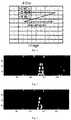
- the three-value image TTT(m,n) shown in Fig. 4 is acquired.
- the positive-direction boundary pixels and the negative-direction boundary pixels can be distinguished in the image that is acquired after the processing.
- the positive-direction boundary pixels may be separately extracted.
- Step 103 according to the positive-direction boundary pixels and the negative-direction boundary pixels, acquiring a positive-direction straight linear segment and a negative-direction straight linear segment that represent boundary trends of the object to be identified.
- the positive-direction boundary pixels and the negative-direction boundary pixels are individually grouped, to respectively acquire a positive-direction-boundary-pixel group and a negative-direction-boundary-pixel group, wherein each of the positive-direction boundary pixels or the negative-direction boundary pixels is connected to the other boundary pixels in its group in the eight directions.
- Fig. 6 shows the schematic diagram of the grouping of the positive-direction-boundary-pixel group.
- the entire image comprises a total of 18278 pixels, among which there are 263 positive-direction boundary pixels.
- 18015 pixels are the background pixels.
- the data of the pixel distribution of each of the positive-direction-boundary-pixel groups are shown in Table 1.
- Table 1 Group number Pixel quantity of each of the positive-direction-boundary-pixel groups Range of the pixel coordinates of each of the positive-directi on -boundary -pixel groups #1 7 v(2,5) h(75,76) #2 8 v(2,5) h(115,116) #3 16 v(2,9) h(150,152) #4 44 v(30,38) h(135,139) #5 53 v(43,52) h(132,138) #6 27 v(55,62) h(131,135) #7 61 v(57,73) h(141,146) #8 35 v(66,73) h(128,133) #9 6 v(72,73) h(72,75) #10 6 v(72,73) h(206,209)
- the boundary pixels of each of the groups have a wide range in the horizontal direction.
- boundary-pixel narrowing in the horizontal direction is performed to the positive-direction-boundary-pixel group and the negative-direction-boundary-pixel group, to acquire respectively a positive-direction-narrowed-boundary-pixel group and a negative-direction-narrowed-boundary-pixel group, wherein the total quantity of the boundary pixels in the horizontal direction within each of the positive-direction-narrowed-boundary-pixel group and the negative-direction-narrowed-boundary-pixel group does not exceed a preset threshold.
- Fig. 7 shows the schematic diagram of the principle of the narrowing of the boundary pixels in the horizontal direction.
- a certain row in a certain positive-direction-boundary-pixel group has 3 positive-direction boundary pixels, and in the positive-direction-narrowed-boundary-pixel group that is acquired after the narrowing of the boundary pixels, merely the pixel in the middle is reserved, and the other two pixels are assigned to be the same as the background pixels.
- a certain row in a certain positive-direction-boundary-pixel group has 4 positive-direction boundary pixels, and in the positive-direction-narrowed-boundary-pixel group that is acquired after the narrowing of the boundary pixels, merely the second pixel or the third pixel from left to right is reserved, and the other three pixels are assigned to be the same as the background pixels.
- Fig. 8 shows the schematic diagram of the grouping of the positive-direction-narrowed-boundary-pixel group.
- the entire image comprises a total of 18278 pixels, among which there are 72 narrowed positive-direction boundary pixels.
- 18206 pixels are the background pixels.
- the data of the pixel distribution of each of the positive-direction-narrowed-boundary-pixel groups are shown in Table 2.
- Table 2 Group number Pixel quantity of each of the positive-direction-boundary-pixel groups Range of the pixel coordinates of each of the positive-directi on -boundary -pixel groups #1 4 v(2,5) h(75,76) #2 4 v(2,5) h(116,116) #3 8 v(2,9) h(151,152) #4 9 v(30,38) h(137,138) #5 10 v(43,52) h(134,136) #6 8 v(55,62) h(132,134) #7 17 v(57,73) h(142,145) #8 8 v(66,73) h(130,132) #9 2 v(72,73) h(74,74) #10 2 v(72,73) h(208,209)
- the positive-direction-narrowed-boundary-pixel group reserves the boundary information in the original image, can represent the boundary trend of the object to be identified, and reduces the complexity of the subsequent image processing.
- Hough transformation is performed to the positive-direction-narrowed-boundary-pixel group and the negative-direction-narrowed-boundary-pixel group, to respectively acquire the positive-direction straight linear segment and the negative-direction straight linear segment.
- a plurality of ineffective groups in the positive-direction-narrowed-boundary-pixel group are eliminated whose area-position distance between the area position where it is located and an average area position of the other groups is greater than a preset distance threshold. That can reduce the subsequent computation burden, and improve the accuracy of the processing result.
- the preset distance threshold may be set according to the known height of the traffic cones, for example, by setting the preset distance threshold to be the known height of the traffic cones, or setting the preset distance threshold to be a multiple of the known height of the traffic cones.
- Hough transformation is performed to the pixels in the positive-direction-narrowed-boundary-pixel group that has been eliminated the ineffective groups, to acquire positive-direction straight line segment that represents a boundary trend of the object to be identified.
- the approach of "acquiring negative-direction straight line segment that represents a boundary trend of the object to be identified” is the same as the approach of "acquiring positive-direction straight line segment that represents a boundary trend of the object to be identified", and is not discussed here in further detail.
- a positive-direction Hough curve and a negative-direction Hough curve are respectively acquired.
- Histogram transformation is performed to the positive-direction Hough curve and the negative-direction Hough curve, to respectively acquire the peak-value quantity and the centroid of the positive-direction Hough curve and the peak-value quantity and the centroid of the negative-direction Hough curve.
- the positive-direction straight line that represents a boundary trend of the object to be identified are acquired, and, according to the peak-value quantity and the centroid of the negative-direction Hough curve, the negative-direction straight line that represents a boundary trend of the object to be identified are acquired.
- the peak-value points are connected in a Hough plane, and the peak-value points that are connected to be the same one group are marked, wherein the result of the marking is shown in Table 3.
- the group #1 comprising the largest peak-value quantity is selected. After the connection of the peak-value points, the centroid of that group is calculated.
- the information of the centroid of the selected group #1 in the Hough plane is as follows:
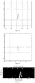
- the positive-direction straight line that represents a boundary trend of the object to be identified may be directly acquired, as shown in Fig. 10 .
- the positive-direction boundary pixels are matched to the positive-direction straight line, to determine two endpoints in the positive-direction straight line, and the line segment between the two endpoints is the positive-direction straight linear segment.
- the process comprises: determining target positive-direction boundary pixels among the positive-direction boundary pixels whose distances from the positive-direction straight line are less than a preset distance; and according to the pixel having the maximum vertical coordinate value in the vertical direction among the target positive-direction boundary pixels, determining a first endpoint of the two endpoints, and, according to the pixel having the minimum vertical coordinate value in the vertical direction among the target positive-direction boundary pixels, determining a second endpoint of the two endpoints.
- the first endpoint is determined in the positive-direction straight line by using the pixel 1 having the maximum vertical coordinate
- the second endpoint is determined in the positive-direction straight line by using the pixel 5 having the minimum vertical coordinate.
- Fig. 12 shows the target positive-direction boundary pixels whose distance from the positive-direction straight line shown in Fig. 10 is less than a preset distance.
- the positive-direction straight linear segment that is determined and acquired by using the target positive-direction boundary pixels is shown in Fig. 13 .
- the negative-direction boundary pixels are matched to the negative-direction straight line, to determine two endpoints in the negative-direction straight line, and the line segment between the two endpoints is the negative-direction straight linear segment.
- the process of determining the negative-direction straight linear segment is similar to that of the positive-direction straight linear segment, and the acquired negative-direction straight linear segment is shown in Fig. 14 , and is not discussed here further.
- Step 104 if the straight linear segments create a target object having a preset height, a preset width and a preset shape, determining the straight linear segments to be peripheral boundaries of the object to be identified.
- the graphic object formed by the positive-direction straight linear segment and/or the negative-direction straight linear segment that are obtained above satisfies a preset height, a preset width and a preset shape
- the positive-direction straight linear segment and/or the negative-direction straight linear segment are correct peripheral boundaries for the object to be identified.
- the object to be identified is a traffic cone
- the self-shadowing has a small influence
- the periphery of the traffic cone can be observed from the edge image; in other words, the actual peripheral surface is estimated from the edge image.
- the straight linear segments that are obtained by the three-value processing meet the height and the width of the traffic cone and the shape of the corresponding construction, it can be determined that the line segments are the peripheral boundaries of the traffic cone.
- the periphery of the traffic cone cannot be properly obtained from the edge image.
- the observed right periphery is instead a shadow boundary.
- the identification of a self-shadowing traffic cone shown in Fig. 17 the right half of the traffic cone has already disappeared, and the width of the cone seems to be reduced. Therefore, the cone might probably be identified to be another object.
- Step 105 selecting, from the straight linear segments, a straight linear segment that is most close to the preset height and a preset angle, and determining the straight linear segment to be a first boundary, wherein the first boundary is a contacting line of a light ray and the object to be identified.
- Step 106 selecting, from the straight linear segments, a straight linear segment that has a height, a position and an angular symmetries same as a height, a position and an angular symmetry of the first boundary and has a distance less than a width of the object to be identified, and determining the straight linear segment to be a second boundary, wherein the second boundary is a contacting line of a light ray and a shadow on the object to be identified in the image data.
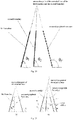
- the illuminance CD is the ideal condition, wherein no shadow exists.
- the right part of the traffic cone has a small area of shadow.
- the shadow covers the entire right half of the cone and part of the left half. Those shadows make it difficult to extract the correct peripheral boundaries.
- the peripheral boundaries completely cannot be identified.
- the second boundary might be erroneously identified to be a peripheral boundary.
- the first boundary is between the left background and the illuminated part
- the second boundary is between the illuminated part and the shadowed part
- the peripheral boundary is between the shadowed part and the right background.
- the peripheral boundary cannot be effectively identified by using the differential image, so after the positive-direction line segment and the negative-direction line segment in the object to be identified have been determined by using the three-value image, they are determined to be the first boundary and the second boundary.
- Step 107 by using positions of the first boundary and the second boundary, drawing a peripheral boundary of the object to be identified, wherein the peripheral boundary is a contacting line of the shadow and a background on the object to be identified in the image data.
- the positions of the peripheral boundaries are further correctly determined.
- the polarities of the edge linear segments are different; that is, one is a positive-direction edge and the other is a negative-direction edge.
- the positive-direction edge or the negative-direction edge is the first boundary.
- the distances between each of the boundaries and the central line of the object to be identified are determined, for example approximately 20 cm, depending on the size of the traffic cone.
- the sum of the angle between the first boundary and the horizontal line and the angle between the second boundary and the horizontal line is 180 degrees.
- the second boundary is a peripheral boundary, and the analysis ends, or else, according to the positions of the first boundary and the second boundary, by referring to the particular parameters of the object to be identified, the correct peripheral boundaries are determined.
- the present disclosure solves the problem in the prior art of lack of a systematic and effective method for identifying the edge of a self-shadowing
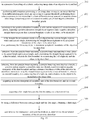
- Fig. 19 is a flow chart of the method for edge identification of a self-shadowing object based on a visual camera according to an embodiment of the present disclosure, which may particularly comprise the following steps: Step 201: in a process of travelling of a vehicle, collecting image data of an object to be identified.
- This step is the same as the step 101, and is not discussed here in detail.
- Step 202 performing differentiation processing to the image data, to acquire an image that has been differentiation-processed, and according to a preset threshold, performing three-value processing to the image that has been differentiation-processed, to acquire a three-value image comprising positive-direction boundary pixels and negative-direction boundary pixels.
- This step is the same as the step 102, and is not discussed here in detail.
- Step 203 according to the positive-direction boundary pixels and the negative-direction boundary pixels, acquiring a positive-direction straight linear segment and a negative-direction straight linear segment that represent boundary trends of the object to be identified.
- This step is the same as the step 103, and is not discussed here in detail.
- Step 204 if the straight linear segments create a target object having a preset height, a preset width and a preset shape, determining the straight linear segments to be peripheral boundaries of the object to be identified.
- Step 205 selecting, from the straight linear segments, a straight linear segment that is most close to the preset height and a preset angle, and determining the straight linear segment to be a first boundary, wherein the first boundary is a contacting line of a light ray and the object to be identified.
- This step is the same as the step 105, and is not discussed here in detail.
- Step 206 selecting, from the straight linear segments, a straight linear segment that has a height, a position and an angular symmetries same as a height, a position and an angular symmetry of the first boundary and has a distance less than a width of the object to be identified, and determining the straight linear segment to be a second boundary, wherein the second boundary is a contacting line of a light ray and a shadow on the object to be identified in the image data.
- This step is the same as the step 106, and is not discussed here in detail.
- Step 207 acquiring an intersection point of extended lines of the first boundary and the second boundary.
- the first boundary and the second boundary are extended upwardly to the intersection point, to determine the intersection point of the extended lines of the first boundary and the second boundary.
- Step 208 acquiring a first angle between the first boundary and a horizontal line.
- the first angle ⁇ 1 between the first boundary and the horizontal line is acquired.
- Step 209 by using a difference between a straight angle and the first angle, obtaining a third angle.
- ⁇ 3 180- ⁇ 1 .
- Step 210 according to the intersection point and the third angle, determining the peripheral boundary of the object to be identified.
- the step 210 comprises substeps A1-A2:
- the step comprises drawing a line segment that passes through the intersection point of the extended lines of the first boundary and the second boundary, and assuming that the line segment is a peripheral boundary; moving the lower end of the assumed peripheral boundary, and causing the angle between the assumed peripheral boundary and the horizontal line to be the same as ⁇ 3 ; and adjusting the distance between the assumed peripheral boundary and the central point of the object to be identified to be 20cm, and adjusting the height to be similar to the height of the first boundary. Accordingly, the area constructed by using the first boundary and the assumed peripheral boundary is consistent with the identification parameters of the traffic cone, and then it can be determined that the assumed peripheral boundary is a suitable peripheral boundary.
- the step 210 may further comprise substeps B1-B4:
- the width w' from the linear segment to the center is the preset width of the object at the center, i.e., the preset height of the object to be identified, which, in the present embodiment, is 20cm, and the numerical value depends on the parameters of the particular object to be identified, and is not limited in the embodiments of the present disclosure.
- the intersection point of the extended lines of the first boundary and the second boundary is determined.
- the preset width is calculated out, and the assumed peripheral boundary is horizontally moved, to cause the width from it to the first boundary to be W", wherein the values of a and b are preset parameters, and are usually 1.
- W " a ⁇ w " + b ⁇ w ′ / w ′ + w "
- the height, the angle and the width from the first boundary of the assumed peripheral boundary are determined, and then it can be determined that the assumed peripheral boundary that has been moved is a suitable peripheral boundary.
- the step may further comprise: substeps C1-C2:
- the texture difference between the two areas separated by the assumed peripheral boundary is investigated, the assumed peripheral boundary is horizontally moved to study the texture difference between the two areas separated by it, and the new boundary that has the maximum texture difference is determined to be a peripheral boundary having a correct boundary. If the maximum difference is greater than a preset threshold, the assumed peripheral boundary is determined to be a suitable peripheral boundary.
- the step 204 is re-entered.
- the step may further comprise: substeps D1-D2:
- the assumed peripheral boundary in order to verify the above determination, by using the horizontal line as the axis, the assumed peripheral boundary is horizontally moved, and the texture difference between the two areas separated by the assumed peripheral boundary is detected, to find the new boundary that has the maximum texture difference, which is determined to be a peripheral boundary having a correct boundary. If the maximum difference is greater than a preset threshold, the assumed peripheral boundary is determined to be a suitable peripheral boundary.
- the clear peripheral line (the first boundary) and the extended line of the shadow boundary (the second boundary) are used to estimate the intersection point, and by starting from the intersection point, the linear segment of the assumed peripheral boundary that has the angle symmetrical with the first boundary is created, and then, after the linear segment has been moved in parallel, the textures on the two sides of the linear segment are judged, when the texture difference is larger, the estimation on the blur peripheral line is more reliable.
- the step 204 is re-entered.
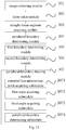
- Fig. 22 is a structural block diagram of the device for edge identification of a self-shadowing object based on a visual camera according to an embodiment of the present disclosure.
- the device comprises:
- Fig. 23 is a structural block diagram of the device for edge identification of a self-shadowing object based on a visual camera according to an embodiment of the present disclosure.
- the device comprises:
- the peripheral-boundary drawing module 307 comprises:
- the peripheral-boundary determining submodule 3074 comprises:
- the peripheral-boundary determining submodule 3074 may further comprise:
- the peripheral-boundary determining submodule 3074 further comprises:
- the peripheral-boundary determining submodule 3074 further comprises:
- an image collecting module configured for, in a process of travelling of a vehicle, collecting image data of an object to be identified; a three-value module configured for performing differentiation processing to the image data, to acquire an image that has been differentiation-processed, and according to a preset threshold, performing three-value processing to the image that has been differentiation-processed, to acquire a three-value image comprising positive-direction boundary pixels and negative-direction boundary pixels; a straight-linear-segment acquiring module configured for, according to the positive-direction boundary pixels and the negative-direction boundary pixels, acquiring a positive-direction straight linear segment and a negative-direction straight linear segment that represent boundary trends of the object to be identified; a peripheral-boundary determining module configured for, if the straight linear segments create a target object having a preset height, a preset width and a preset shape, determining the straight linear segments to be peripheral boundaries of the object to be identified; if no, by executing the following modules,
- the above-described device embodiments are merely illustrative, wherein the units that are described as separate components may or may not be physically separate, and the components that are displayed as units may or may not be physical units; in other words, they may be located at the same one location, and may also be distributed to a plurality of network units. Part or all of the modules may be selected according to the actual demands to realize the purposes of the solutions of the embodiments. A person skilled in the art can understand and implement the technical solutions without paying creative work.
- Each component embodiment of the present disclosure may be implemented by hardware, or by software modules that are operated on one or more processors, or by a combination thereof.
- a person skilled in the art should understand that some or all of the functions of some or all of the components of the calculating and processing device according to the embodiments of the present disclosure may be implemented by using a microprocessor or a digital signal processor (DSP) in practice.
- DSP digital signal processor
- the present disclosure may also be implemented as apparatus or device programs (for example, computer programs and computer program products) for implementing part of or the whole of the method described herein.
- Such programs for implementing the present disclosure may be stored in a computer-readable medium, or may be in the form of one or more signals. Such signals may be downloaded from an Internet website, or provided on a carrier signal, or provided in any other forms.
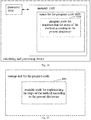
- Fig. 24 shows a calculating and processing device that can implement the method according to the present disclosure.
- the calculating and processing device traditionally comprises a processor 1010 and a computer program product or computer-readable medium in the form of a memory 1020.
- the memory 1020 may be electronic memories such as flash memory, EEPROM (Electrically Erasable Programmable Read Only Memory), EPROM, hard disk or ROM.
- the memory 1020 has the storage space 1030 of the program code 1031 for implementing any steps of the above method.
- the storage space 1031 for program code may contain program codes 1031 for individually implementing each of the steps of the above method. Those program codes may be read from one or more computer program products or be written into the one or more computer program products.
- Those computer program products include program code carriers such as hard disk, compact disk (CD), memory card or floppy disk as shown in Fig. 25 .
- Such computer program products are usually portable or fixed storage units.
- the storage unit may have storage segments or storage spaces with similar arrangement to the memory 1020 of the calculating and processing device in Figure 24 .
- the program codes may for example be compressed in a suitable form.
- the storage unit contains a computer-readable code 1031', which can be read by a processor like 1010. When those codes are executed by the calculating and processing device, the codes cause the calculating and processing device to implement each of the steps of the method described above.
- any reference signs between parentheses should not be construed as limiting the claims.
- the word “comprise” does not exclude elements or steps that are not listed in the claims.
- the word “a” or “an” preceding an element does not exclude the existing of a plurality of such elements.
- the present disclosure may be implemented by means of hardware comprising several different elements and by means of a properly programmed computer. In unit claims that list several devices, some of those devices may be embodied by the same item of hardware.
- the words first, second, third and so on do not denote any order. Those words may be interpreted as names.
Landscapes
- Engineering & Computer Science (AREA)
- Physics & Mathematics (AREA)
- Theoretical Computer Science (AREA)
- General Physics & Mathematics (AREA)
- Multimedia (AREA)
- Computer Vision & Pattern Recognition (AREA)
- Data Mining & Analysis (AREA)
- Artificial Intelligence (AREA)
- Life Sciences & Earth Sciences (AREA)
- Bioinformatics & Cheminformatics (AREA)
- Bioinformatics & Computational Biology (AREA)
- Evolutionary Biology (AREA)
- Evolutionary Computation (AREA)
- General Engineering & Computer Science (AREA)
- Probability & Statistics with Applications (AREA)
- Image Analysis (AREA)
- Image Processing (AREA)
Abstract
Description
- The present application claims the priority of the Chinese patent application filed on June 29th, 2018 before the Chinese Patent Office with the application number of
201810712073.1 - The present disclosure relates to the technical field of autopilot, and particularly relates to a method and device for edge identification of a self-shadowing object based on a visual camera and a vehicle.
- ADAS (Advanced Driver Assistant Systems) can, by using various sensors installed onboard the car, in the process of the travelling of the car, sense the ambient environment at any time, collect the data, identify and track objects of different movement states, and, by using the map data of the navigator, perform systematic computation and analysis, thereby enabling the driver to be aware of the potential dangers in advance, to effectively improve the comfortableness and the safety of automobile driving. Especially in the field of autopilot, some sensors in the ADAS, such as the vision camera, have the function of obtaining two-dimensional images, similar to that of the human being, so they can serve as the main sensors in the ADAS in autopilot vehicles.
- The vision camera utilizes the function of image processing to catch the road images during vehicle driving, and assists the driver in accurately identifying the road in the autopilot mode, which is an important research topic in the field of autopilot. However, regarding self-shadowing objects, because the shadow self-shielding that they generate under illumination generates boundary that prevent the objects from being identified, and the boundary varies with the direction of the illumination, that is, the boundary moves on the surface of the object, the identification of the boundaries of self-shadowing objects is very difficult.
- Currently, there is no effective and systematic method for effectively identifying the boundaries of the self-shadowing image that are formed by a self-shadowing object, which affects the identification of the self-shadowing object in the self-shadowing image.
- The above description is merely a summary of the technical solutions of the present disclosure. In order to more clearly know the elements of the present disclosure to enable the implementation according to the contents of the description, and in order to make the above and other purposes, features and advantages of the present disclosure more apparent and understandable, the particular embodiments of the present disclosure are provided below.
- To solve the above problems, the technical solutions of the present disclosure are realized as follows:
- A method for edge identification of a self-shadowing object based on a visual camera, wherein the method comprises, in a process of travelling of a vehicle, collecting image data of an object to be identified;
- performing differentiation processing to the image data, to acquire an image that has been differentiation-processed, and according to a preset threshold, performing three-value processing to the image that has been differentiation-processed, to acquire a three-value image comprising positive-direction boundary pixels and negative-direction boundary pixels;
- according to the positive-direction boundary pixels and the negative-direction boundary pixels, acquiring a positive-direction straight linear segment and a negative-direction straight linear segment that represent boundary trends of the object to be identified;
- if the straight linear segments create a target object having a preset height, a preset width and a preset shape, determining the straight linear segments to be peripheral boundaries of the object to be identified; and
- if no, performing the following steps, to determine peripheral boundaries of the object to be identified:
- selecting, from the straight linear segments, a straight linear segment that is most close to the preset height and a preset angle, and determining the straight linear segment to be a first boundary, wherein the first boundary is a contacting line of a light ray and the object to be identified;
- selecting, from the straight linear segments, a straight linear segment that has a height, a position and an angular symmetries same as a height, a position and an angular symmetry of the first boundary and has a distance less than a width of the object to be identified, and determining the straight linear segment to be a second boundary, wherein the second boundary is a contacting line of a light ray and a shadow on the object to be identified in the image data; and
- by using positions of the first boundary and the second boundary, drawing a peripheral boundary of the object to be identified, wherein the peripheral boundary is a contacting line of the shadow and a background on the object to be identified in the image data.
- Optionally, the step of, by using the positions of the first boundary and the second boundary, drawing the peripheral boundary of the object to be identified comprises:
- acquiring an intersection point of extended lines of the first boundary and the second boundary;
- acquiring a first angle between the first boundary and a horizontal line;
- by using a difference between a straight angle and the first angle, obtaining a third angle; and
- according to the intersection point and the third angle, determining the peripheral boundary of the object to be identified.
- Optionally, the step of, according to the intersection point and the third angle, determining the peripheral boundary of the object to be identified comprises:
- drawing a line segment that passes through the intersection point of the extended lines of the first boundary and the second boundary, and causing an included angle between the line segment and a horizontal line to be the third angle; and
- determining the line segment to be the peripheral boundary of the object to be identified.
- Optionally, the step of, according to the intersection point and the third angle, determining the peripheral boundary of the object to be identified comprises:
- determining a first height value of the first boundary and a first distance between the first boundary and a predetermined central line;
- drawing a line segment that passes through the intersection point of the extended lines of the first boundary and the second boundary, and causing an included angle between the line segment and a horizontal line to be the third angle;
- moving the line segment in parallel, to cause a distance between the line segment and the predetermined central line to be equal to the first distance, and a height of the line segment to be equal to the first height value; and
- determining the line segment that has been moved in parallel to be the peripheral boundary of the object to be identified.
- Optionally, before the step of determining the line segment that has been moved in parallel to be the peripheral boundary of the object to be identified, the method further comprises:
- judging whether a texture difference between a shadow area on the object to be identified and a natural-background area on the object to be identified that are separated by the line segment that has been moved in parallel exceeds a preset threshold; and
- if the texture difference exceeds the preset threshold, entering the step of determining the line segment that has been moved in parallel to be the peripheral boundary of the object to be identified, and if no, re-entering the step of determining the peripheral boundary of the object to be identified.
- Optionally, before the step of determining the line segment that has been moved in parallel to be the peripheral boundary of the object to be identified, the method further comprises:
- by moving in parallel the line segment that has been moved in parallel, judging a maximum value of a texture difference between a shadow area on the object to be identified and a natural-background area on the object to be identified that are separated by the line segment that has been moved in parallel; and
- if the maximum value of the texture difference is greater than a preset threshold, entering the step of determining the line segment that has been moved in parallel to be the peripheral boundary of the object to be identified, and if no, re-entering the step of determining the peripheral boundary of the object to be identified.
- As compared with the prior art, the method for edge identification of a self-shadowing object based on a visual camera according to the present disclosure has the following advantages: by, in a process of travelling of a vehicle, acquiring image data of the object to be identified; performing differentiation processing to the image data, to acquire an image that has been differentiation-processed, and according to a preset threshold, performing three-value processing to the image that has been differentiation-processed, to acquire a three-value image comprising positive-direction boundary pixels and negative-direction boundary pixels; according to the positive-direction boundary pixels and the negative-direction boundary pixels, acquiring a positive-direction straight linear segment and a negative-direction straight linear segment that represent boundary trends of the object to be identified; if the straight linear segments create a target object having a preset height, a preset width and a preset shape, determining the straight linear segments to be peripheral boundaries of the object to be identified; or else, by determining a first boundary and a second boundary, in turn determining the peripheral boundaries of the object to be identified, the method has the advantageous effect of systematic and effective boundary identification of a self-shadowing image.
- Another object of the present disclosure is to provide a device for edge identification of a self-shadowing object based on a visual camera, wherein the device comprises: an image collecting module configured for, in a process of travelling of a vehicle, collecting image data of an object to be identified;
a three-value module configured for performing differentiation processing to the image data, to acquire an image that has been differentiation-processed, and according to a preset threshold, performing three-value processing to the image that has been differentiation-processed, to acquire a three-value image comprising positive-direction boundary pixels and negative-direction boundary pixels;
a straight-linear-segment acquiring module configured for, according to the positive-direction boundary pixels and the negative-direction boundary pixels, acquiring a positive-direction straight linear segment and a negative-direction straight linear segment that represent boundary trends of the object to be identified;
a peripheral-boundary determining module configured for, if the straight linear segments create a target object having a preset height, a preset width and a preset shape, determining the straight linear segments to be peripheral boundaries of the object to be identified; and
if no, by executing the following modules, determining peripheral boundaries of the object to be identified: - a first-boundary determining module configured for selecting, from the straight linear segments, a straight linear segment that is most close to the preset height and a preset angle, and determining the straight linear segment to be a first boundary, wherein the first boundary is a contacting line of a light ray and the object to be identified;
- a second-boundary determining module configured for selecting, from the straight linear segments, a straight linear segment that has a height, a position and an angular symmetries same as a height, a position and an angular symmetry of the first boundary and has a distance less than a width of the object to be identified, and determining the straight linear segment to be a second boundary, wherein the second boundary is a contacting line of a light ray and a shadow on the object to be identified in the image data; and
- a peripheral-boundary drawing module configured for, by using positions of the first boundary and the second boundary, drawing a peripheral boundary of the object to be identified, wherein the peripheral boundary is a contacting line of the shadow and a background on the object to be identified in the image data.
- Optionally, the peripheral-boundary drawing module comprises:
- an extended-line-intersection-point acquiring submodule configured for acquiring an intersection point of extended lines of the first boundary and the second boundary;
- a first-angle acquiring submodule configured for acquiring a first angle between the first boundary and a horizontal line;
- a third-angle acquiring submodule configured for, by using a difference between a straight angle and the first angle, obtaining a third angle; and
- a peripheral-boundary determining submodule configured for, according to the intersection point and the third angle, determining the peripheral boundary of the object to be identified.
- Optionally, the peripheral-boundary determining submodule comprises:
- a line-segment drawing unit configured for drawing a line segment that passes through the intersection point of the extended lines of the first boundary and the second boundary, and causing an included angle between the line segment and a horizontal line to be the third angle; and
- a peripheral-boundary determining unit configured for determining the line segment to be the peripheral boundary of the object to be identified.
- Optionally, the peripheral-boundary determining submodule comprises:
- a first-distance determining unit configured for determining a first height value of the first boundary and a first distance between the first boundary and a predetermined central line;
- a line-segment-included-angle determining unit configured for drawing a line segment that passes through the intersection point of the extended lines of the first boundary and the second boundary, and causing an included angle between the line segment and a horizontal line to be the third angle;
- a line-segment translating unit configured for moving the line segment in parallel, to cause a distance between the line segment and the predetermined central line to be equal to the first distance, and a height of the line segment to be equal to the first height value; and
- a peripheral-boundary drawing module configured for determining the line segment that has been moved in parallel to be the peripheral boundary of the object to be identified.
- Optionally, the device further comprises: a judging unit configured for judging whether a texture difference between a shadow area on the object to be identified and a natural-background area on the object to be identified that are separated by the line segment that has been moved in parallel exceeds a preset threshold; and
a determining unit configured for, if the texture difference exceeds the preset threshold, executing the peripheral-boundary determining unit, and if no, re-executing the peripheral-boundary drawing module. - Optionally, the device further comprises: a texture-difference-maximum-value determining unit configured for, by moving in parallel the line segment that has been moved in parallel, judging a maximum value of a texture difference between a shadow area on the object to be identified and a natural-background area on the object to be identified that are separated by the line segment that has been moved in parallel; and
an executing unit configured for, if the maximum value of the texture difference is greater than a preset threshold, executing the line-segment translating unit, and if no, re-executing the peripheral-boundary drawing module. - The device for edge identification of a self-shadowing object based on a visual camera has the advantage over the prior art the same as that of the method for edge identification of a self-shadowing object based on a visual camera, which is not discussed here further.
- Preferably, another object of the present disclosure is to provide a vehicle, wherein the vehicle comprises the method and device for edge identification of a self-shadowing object based on a visual camera described above.
- In order to more clearly illustrate the technical solutions of the embodiments of the present disclosure or the prior art, the figures that are required to describe the embodiments or the prior art will be briefly introduced below. Apparently, the figures that are described below are embodiments of the present disclosure, and a person skilled in the art can obtain other figures according to these figures without paying creative work.
-
Fig. 1 is a flow chart of the method for edge identification of a self-shadowing object based on a visual camera according to the first embodiment of the present disclosure; -
Fig. 2 is a schematic diagram of the result of the image processing according to an embodiment of the present disclosure; -
Fig. 3 is a schematic diagram of the result of the image processing according to an embodiment of the present disclosure; -
Fig. 4 is a schematic diagram of the principle of the image processing according to an embodiment of the present disclosure; -
Fig. 5 is a schematic diagram of the result of the image processing according to an embodiment of the present disclosure; -
Fig. 6 is a schematic diagram of the principle of the image processing according to an embodiment of the present disclosure; -
Fig. 7 is a schematic diagram of the result of the image processing according to an embodiment of the present disclosure; -
Fig. 8 is a schematic diagram of the result of the image processing according to an embodiment of the present disclosure; -
Fig. 9 is a schematic diagram of the principle of the image processing according to an embodiment of the present disclosure; -
Fig. 10 is a schematic diagram of the result of the image processing according to an embodiment of the present disclosure; -
Fig. 11 is a schematic diagram of the principle of the image processing according to an embodiment of the present disclosure; -
Fig. 12 is a schematic diagram of the result of the image processing according to an embodiment of the present disclosure; -
Fig. 13 is a schematic diagram of the result of the image processing according to an embodiment of the present disclosure; -
Fig. 14 is a schematic diagram of the principle of the image processing according to an embodiment of the present disclosure; -
Fig. 15 is a schematic diagram of the principle of the image processing according to an embodiment of the present disclosure; -
Fig. 16 is a schematic diagram of the principle of the image processing according to an embodiment of the present disclosure; -
Fig. 17 is a schematic diagram of the principle of the image processing according to an embodiment of the present disclosure; -
Fig. 18 is a schematic diagram of the principle of the image processing according to an embodiment of the present disclosure; -
Fig. 19 is a flow chart of the method for edge identification of a self-shadowing object based on a visual camera according to the second embodiment of the present disclosure; -
Fig. 20 is a schematic diagram of the principle of the image processing according to an embodiment of the present disclosure; -
Fig. 21 is a schematic diagram of the principle of the image processing according to an embodiment of the present disclosure; -
Fig. 22 is a structural block diagram of the device for edge identification of a self-shadowing object based on a visual camera according to the third embodiment of the present disclosure; -
Fig. 23 is a structural block diagram of the device for edge identification of a self-shadowing object based on a visual camera according to the third embodiment of the present disclosure; -
Fig. 24 is a schematic structural diagram of the computer processing device according to an embodiment of the present disclosure; and -
Fig. 25 is a schematic structural diagram of the storage unit according to an embodiment of the present disclosure. - In order to make the objects, the technical solutions and the advantages of the embodiments of the present disclosure clearer, the technical solutions of the embodiments of the present disclosure will be clearly and completely described below with reference to the drawings of the embodiments of the present disclosure. Apparently, the described embodiments are merely certain embodiments of the present disclosure, rather than all of the embodiments. All of the other embodiments that a person skilled in the art obtains on the basis of the embodiments of the present disclosure without paying creative work fall within the protection scope of the present disclosure.
-
Fig. 1 is a flow chart of the method for edge identification of a self-shadowing object based on a visual camera according to an embodiment of the present disclosure, which may particularly comprise the following steps:
Step 101: in a process of travelling of a vehicle, collecting image data of an object to be identified. - In an embodiment of the present disclosure, a monocular vision system may be employed. Preferably, the vision system can acquire an image of pixels larger than 1M by using a telephoto lens.
- Exemplarily, the acquired image is shown in
Fig. 2. Fig. 2 may be a global image acquired from the monocular camera. In order to improve the efficiency of the image processing in the later stage,Fig. 2 may also be a sub-image containing the object to be identified that is scissored from the global image. As shown inFig. 2 , it can be observed that the boundary of the object to be identified is blurry and discontinuous. - Step 102: performing differentiation processing to the image data, to acquire an image that has been differentiation-processed, and according to a preset threshold, performing three-value processing to the image that has been differentiation-processed, to acquire a three-value image comprising positive-direction boundary pixels and negative-direction boundary pixels.
- In an embodiment of the present disclosure, particularly, the image processing to the image may be performed by using a Sobel Filter.
Fig. 2 shows a schematic diagram of the process of the image processing by using a Sobel Filter FFF.
- As shown in
Fig. 3 , a Raster Scan scans each of the pixel points in the image in the horizontal direction, and transforms the original image XXX(m,n) into a differential image YYY(m,n), which may particularly refer to the following code:
   for m=2:mm-1
         for n=2:nn-1
               W+XXX(m-1:m+1,n-1:n+1);
               WF=W.*FFF;
               YYY(m,n)=sum(WF(:));
         end
   end
     for m=1:mm
           for n=1:nn
           if YYY(m,n)>Threshold
           TTT(m,n)=-1
           else if YYY(m,n)<-Threshold
           end
     end
  end
| Group number | Pixel quantity of each of the positive-direction-boundary-pixel groups | Range of the pixel coordinates of each of the positive-directi on -boundary - |
| # | ||
| 1 | 7 | v(2,5) h(75,76) |
| #2 | 8 | v(2,5) h(115,116) |
| #3 | 16 | v(2,9) h(150,152) |
| #4 | 44 | v(30,38) h(135,139) |
| #5 | 53 | v(43,52) h(132,138) |
| #6 | 27 | v(55,62) h(131,135) |
| #7 | 61 | v(57,73) h(141,146) |
| #8 | 35 | v(66,73) h(128,133) |
| #9 | 6 | v(72,73) h(72,75) |
| #10 | 6 | v(72,73) h(206,209) |
| Group number | Pixel quantity of each of the positive-direction-boundary-pixel groups | Range of the pixel coordinates of each of the positive-directi on -boundary - |
| # | ||
| 1 | 4 | v(2,5) h(75,76) |
| #2 | 4 | v(2,5) h(116,116) |
| #3 | 8 | v(2,9) h(151,152) |
| #4 | 9 | v(30,38) h(137,138) |
| #5 | 10 | v(43,52) h(134,136) |
| #6 | 8 | v(55,62) h(132,134) |
| #7 | 17 | v(57,73) h(142,145) |
| #8 | 8 | v(66,73) h(130,132) |
| #9 | 2 | v(72,73) h(74,74) |
| #10 | 2 | v(72,73) h(208,209) |
 | %y: upward |
 |
| H(1:nnR,1:nnAng): | histogram is binarized. |
| binH(1:nnR,1:nnAng)=H*0; % H: | histogram |
| binH(H>=threshold)=1; | % Binary |
| HL=fnc_Labeling(binH); | % Labeling of binary image |
| nL=max(HL(:)) | % number of peaks (labels) |
| rrG(1:nL); | % CG of the range for each connected region |
| aangG(1:nL); | % CG of the angles |
| rrG & aangG: n1=2 | |
| rrG: 50, 110, | |
| aangG: 151, 31, |
| # 1 | number of peaks=11 | range (14, 16), ang (347, 354) |
| # 2 | number of peaks=1 | range (15, 15), ang (16, 16) |
| # 3 | number of peaks=1 | range (16, 16), ang (14, 14) |
| # 4 | number of peaks=1 | range (17, 17), ang (343, 343) |
- rrG & aangG: n1=1
- rrG: 14,
- angG: 351,
Step 201: in a process of travelling of a vehicle, collecting image data of an object to be identified.
if no, performing the following steps, to determine peripheral boundaries of the object to be identified:
Step 205: selecting, from the straight linear segments, a straight linear segment that is most close to the preset height and a preset angle, and determining the straight linear segment to be a first boundary, wherein the first boundary is a contacting line of a light ray and the object to be identified.
- substep A1: drawing a line segment that passes through the intersection point of the extended lines of the first boundary and the second boundary, and causing an included angle between the line segment and a horizontal line to be the third angle; and
- substep A2: determining the line segment to be the peripheral boundary of the object to be identified.
- substep B1: determining a first height value of the first boundary and a first distance between the first boundary and a predetermined central line;
- substep B2: drawing a line segment that passes through the intersection point of the extended lines of the first boundary and the second boundary, and causing an included angle between the line segment and a horizontal line to be the third angle;
- substep B3: moving the line segment in parallel, to cause a distance between the line segment and the predetermined central line to be equal to the first distance, and a height of the line segment to be equal to the first height value; and
- substep B4: determining the line segment that has been moved in parallel to be the peripheral boundary of the object to be identified.

- substep C1: judging whether a texture difference between a shadow area on the object to be identified and a natural-background area on the object to be identified that are separated by the line segment that has been moved in parallel exceeds a preset threshold; and
- substep C2: if the texture difference exceeds the preset threshold, entering the substep A2 or B4, or else re-entering the
step 204.
- substep D1: by moving in parallel the line segment that has been moved in parallel, judging a maximum value of a texture difference between a shadow area on the object to be identified and a natural-background area on the object to be identified that are separated by the line segment that has been moved in parallel; and
- substep D2: if the maximum value of the texture difference is greater than a preset threshold, entering the substep A2 or B4, or else re-entering the
step 204.
- an
image collecting module 301 configured for, in a process of travelling of a vehicle, collecting image data of an object to be identified; - a three-
value module 302 configured for performing differentiation processing to the image data, to acquire an image that has been differentiation-processed, and according to a preset threshold, performing three-value processing to the image that has been differentiation-processed, to acquire a three-value image comprising positive-direction boundary pixels and negative-direction boundary pixels; - a straight-linear-
segment acquiring module 303 configured for, according to the positive-direction boundary pixels and the negative-direction boundary pixels, acquiring a positive-direction straight linear segment and a negative-direction straight linear segment that represent boundary trends of the object to be identified; - a peripheral-
boundary determining module 304 configured for, if the straight linear segments create a target object having a preset height, a preset width and a preset shape, determining the straight linear segments to be peripheral boundaries of the object to be identified; and - if no, by executing the following modules, determining peripheral boundaries of the object to be identified:
- a first-
boundary determining module 305 configured for selecting, from the straight linear segments, a straight linear segment that is most close to the preset height and a preset angle, and determining the straight linear segment to be a first boundary, wherein the first boundary is a contacting line of a light ray and the object to be identified; - a second-
boundary determining module 306 configured for selecting, from the straight linear segments, a straight linear segment that has a height, a position and an angular symmetries same as a height, a position and an angular symmetry of the first boundary and has a distance less than a width of the object to be identified, and determining the straight linear segment to be a second boundary, wherein the second boundary is a contacting line of a light ray and a shadow on the object to be identified in the image data; and - a peripheral-
boundary drawing module 307 configured for, by using positions of the first boundary and the second boundary, drawing a peripheral boundary of the object to be identified, wherein the peripheral boundary is a contacting line of the shadow and a background on the object to be identified in the image data.
- a first-
- an
image collecting module 301 configured for, in a process of travelling of a vehicle, collecting image data of an object to be identified; - a three-
value module 302 configured for performing differentiation processing to the image data, to acquire an image that has been differentiation-processed, and according to a preset threshold, performing three-value processing to the image that has been differentiation-processed, to acquire a three-value image comprising positive-direction boundary pixels and negative-direction boundary pixels; - a straight-linear-
segment acquiring module 303 configured for, according to the positive-direction boundary pixels and the negative-direction boundary pixels, acquiring a positive-direction straight linear segment and a negative-direction straight linear segment that represent boundary trends of the object to be identified; - a peripheral-
boundary determining module 304 configured for, if the straight linear segments create a target object having a preset height, a preset width and a preset shape, determining the straight linear segments to be peripheral boundaries of the object to be identified; and - if no, by executing the following modules, determining peripheral boundaries of the object to be identified:
- a first-
boundary determining module 305 configured for selecting, from the straight linear segments, a straight linear segment that is most close to the preset height and a preset angle, and determining the straight linear segment to be a first boundary, wherein the first boundary is a contacting line of a light ray and the object to be identified; - a second-
boundary determining module 306 configured for selecting, from the straight linear segments, a straight linear segment that has a height, a position and an angular symmetries same as a height, a position and an angular symmetry of the first boundary and has a distance less than a width of the object to be identified, and determining the straight linear segment to be a second boundary, wherein the second boundary is a contacting line of a light ray and a shadow on the object to be identified in the image data; and - a peripheral-
boundary drawing module 307 configured for, by using positions of the first boundary and the second boundary, drawing a peripheral boundary of the object to be identified, wherein the peripheral boundary is a contacting line of the shadow and a background on the object to be identified in the image data.
- a first-
- an extended-line-intersection-point acquiring submodule 3071 configured for acquiring an intersection point of extended lines of the first boundary and the second boundary;
- a first-angle acquiring submodule 3072 configured for acquiring a first angle between the first boundary and a horizontal line;
- a third-angle acquiring submodule 3073 configured for, by using a difference between a straight angle and the first angle, obtaining a third angle; and
- a peripheral-boundary determining submodule 3074 configured for, according to the intersection point and the third angle, determining the peripheral boundary of the object to be identified.
- a line-segment drawing unit configured for drawing a line segment that passes through the intersection point of the extended lines of the first boundary and the second boundary, and causing an included angle between the line segment and a horizontal line to be the third angle; and
- a peripheral-boundary determining unit configured for determining the line segment to be the peripheral boundary of the object to be identified.
- a first-distance determining unit configured for determining a first height value of the first boundary and a first distance between the first boundary and a predetermined central line;
- a line-segment-included-angle determining unit configured for drawing a line segment that passes through the intersection point of the extended lines of the first boundary and the second boundary, and causing an included angle between the line segment and a horizontal line to be the third angle;
- a line-segment translating unit configured for moving the line segment in parallel, to cause a distance between the line segment and the predetermined central line to be equal to the first distance, and a height of the line segment to be equal to the first height value; and
- a peripheral-boundary drawing module configured for determining the line segment that has been moved in parallel to be the peripheral boundary of the object to be identified.
- a judging unit configured for judging whether a texture difference between a shadow area on the object to be identified and a natural-background area on the object to be identified that are separated by the line segment that has been moved in parallel exceeds a preset threshold; and
- a determining unit configured for, if the texture difference exceeds the preset threshold, executing the peripheral-boundary determining unit, and if no, re-executing the peripheral-boundary drawing module.
- a texture-difference-maximum-value determining unit configured for, by moving in parallel the line segment that has been moved in parallel, judging a maximum value of a texture difference between a shadow area on the object to be identified and a natural-background area on the object to be identified that are separated by the line segment that has been moved in parallel; and
- an executing unit configured for, if the maximum value of the texture difference is greater than a preset threshold, executing the line-segment translating unit, and if no, re-executing the peripheral-boundary drawing module.
Claims (15)
- A method for edge identification of a self-shadowing object based on a visual camera, wherein the method comprises:in a process of travelling of a vehicle, collecting image data of an object to be identified;performing differentiation processing to the image data, to acquire an image that has been differentiation-processed, and according to a preset threshold, performing three-value processing to the image that has been differentiation-processed, to acquire a three-value image comprising positive-direction boundary pixels and negative-direction boundary pixels;according to the positive-direction boundary pixels and the negative-direction boundary pixels, acquiring a positive-direction straight linear segment and a negative-direction straight linear segment that represent boundary trends of the object to be identified;if the straight linear segments create a target object having a preset height, a preset width and a preset shape, determining the straight linear segments to be peripheral boundaries of the object to be identified; andif no, performing the following steps, to determine peripheral boundaries of the object to be identified:selecting, from the straight linear segments, a straight linear segment that is most close to the preset height and a preset angle, and determining the straight linear segment to be a first boundary, wherein the first boundary is a contacting line of a light ray and the object to be identified;selecting, from the straight linear segments, a straight linear segment that has a height, a position and an angular symmetries same as a height, a position and an angular symmetry of the first boundary and has a distance less than a width of the object to be identified, and determining the straight linear segment to be a second boundary, wherein the second boundary is a contacting line of a light ray and a shadow on the object to be identified in the image data; andby using positions of the first boundary and the second boundary, drawing a peripheral boundary of the object to be identified, wherein the peripheral boundary is a contacting line of the shadow and a background on the object to be identified in the image data.
- The method according to claim 1, wherein the step of, by using the positions of the first boundary and the second boundary, drawing the peripheral boundary of the object to be identified comprises:acquiring an intersection point of extended lines of the first boundary and the second boundary;acquiring a first angle between the first boundary and a horizontal line;by using a difference between a straight angle and the first angle, obtaining a third angle; andaccording to the intersection point and the third angle, determining the peripheral boundary of the object to be identified.
- The method according to claim 2, wherein the step of, according to the intersection point and the third angle, determining the peripheral boundary of the object to be identified comprises:drawing a line segment that passes through the intersection point of the extended lines of the first boundary and the second boundary, and causing an included angle between the line segment and a horizontal line to be the third angle; anddetermining the line segment to be the peripheral boundary of the object to be identified.
- The method according to claim 2, wherein the step of, according to the intersection point and the third angle, determining the peripheral boundary of the object to be identified comprises:determining a first height value of the first boundary and a first distance between the first boundary and a predetermined central line;drawing a line segment that passes through the intersection point of the extended lines of the first boundary and the second boundary, and causing an included angle between the line segment and a horizontal line to be the third angle;moving the line segment in parallel, to cause a distance between the line segment and the predetermined central line to be equal to the first distance, and a height of the line segment to be equal to the first height value; anddetermining the line segment that has been moved in parallel to be the peripheral boundary of the object to be identified.
- The method according to claim 3 or 4, wherein before the step of determining the line segment that has been moved in parallel to be the peripheral boundary of the object to be identified, the method further comprises:judging whether a texture difference between a shadow area on the object to be identified and a natural-background area on the object to be identified that are separated by the line segment that has been moved in parallel exceeds a preset threshold; andif the texture difference exceeds the preset threshold, entering the step of determining the line segment that has been moved in parallel to be the peripheral boundary of the object to be identified, and if no, re-entering the step of determining the peripheral boundary of the object to be identified.
- The method according to claim 3 or 4, wherein before the step of determining the line segment that has been moved in parallel to be the peripheral boundary of the object to be identified, the method further comprises:by moving in parallel the line segment that has been moved in parallel, judging a maximum value of a texture difference between a shadow area on the object to be identified and a natural-background area on the object to be identified that are separated by the line segment that has been moved in parallel; andif the maximum value of the texture difference is greater than a preset threshold, entering the step of determining the line segment that has been moved in parallel to be the peripheral boundary of the object to be identified, and if no, re-entering the step of determining the peripheral boundary of the object to be identified.
- A device for edge identification of a self-shadowing object based on a visual camera, wherein the device comprises:an image collecting module configured for, in a process of travelling of a vehicle, collecting image data of an object to be identified;a three-value module configured for performing differentiation processing to the image data, to acquire an image that has been differentiation-processed, and according to a preset threshold, performing three-value processing to the image that has been differentiation-processed, to acquire a three-value image comprising positive-direction boundary pixels and negative-direction boundary pixels;a straight-linear-segment acquiring module configured for, according to the positive-direction boundary pixels and the negative-direction boundary pixels, acquiring a positive-direction straight linear segment and a negative-direction straight linear segment that represent boundary trends of the object to be identified;a peripheral-boundary determining module configured for, if the straight linear segments create a target object having a preset height, a preset width and a preset shape, determining the straight linear segments to be peripheral boundaries of the object to be identified; andif no, by executing the following modules, determining peripheral boundaries of the object to be identified:a first-boundary determining module configured for selecting, from the straight linear segments, a straight linear segment that is most close to the preset height and a preset angle, and determining the straight linear segment to be a first boundary, wherein the first boundary is a contacting line of a light ray and the object to be identified;a second-boundary determining module configured for selecting, from the straight linear segments, a straight linear segment that has a height, a position and an angular symmetries same as a height, a position and an angular symmetry of the first boundary and has a distance less than a width of the object to be identified, and determining the straight linear segment to be a second boundary, wherein the second boundary is a contacting line of a light ray and a shadow on the object to be identified in the image data; anda peripheral-boundary drawing module configured for, by using positions of the first boundary and the second boundary, drawing a peripheral boundary of the object to be identified, wherein the peripheral boundary is a contacting line of the shadow and a background on the object to be identified in the image data.
- The device according to claim 7, wherein the peripheral-boundary drawing module comprises:an extended-line-intersection-point acquiring submodule configured for acquiring an intersection point of extended lines of the first boundary and the second boundary;a first-angle acquiring submodule configured for acquiring a first angle between the first boundary and a horizontal line;a third-angle acquiring submodule configured for, by using a difference between a straight angle and the first angle, obtaining a third angle; anda peripheral-boundary determining submodule configured for, according to the intersection point and the third angle, determining the peripheral boundary of the object to be identified.
- The device according to claim 8, wherein the peripheral-boundary determining submodule comprises:a line-segment drawing unit configured for drawing a line segment that passes through the intersection point of the extended lines of the first boundary and the second boundary, and causing an included angle between the line segment and a horizontal line to be the third angle; anda peripheral-boundary determining unit configured for determining the line segment to be the peripheral boundary of the object to be identified.
- The device according to claim 8, wherein the peripheral-boundary determining submodule comprises:a first-distance determining unit configured for determining a first height value of the first boundary and a first distance between the first boundary and a predetermined central line;a line-segment-included-angle determining unit configured for drawing a line segment that passes through the intersection point of the extended lines of the first boundary and the second boundary, and causing an included angle between the line segment and a horizontal line to be the third angle;a line-segment translating unit configured for moving the line segment in parallel, to cause a distance between the line segment and the predetermined central line to be equal to the first distance, and a height of the line segment to be equal to the first height value; anda peripheral-boundary drawing module configured for determining the line segment that has been moved in parallel to be the peripheral boundary of the object to be identified.
- The device according to claim 9 or 10, wherein the device further comprises:a judging unit configured for judging whether a texture difference between a shadow area on the object to be identified and a natural-background area on the object to be identified that are separated by the line segment that has been moved in parallel exceeds a preset threshold; anda determining unit configured for, if the texture difference exceeds the preset threshold, executing the peripheral-boundary determining unit, and if no, re-executing the peripheral-boundary drawing module.
- The device according to claim 9 or 10, wherein the device further comprises:a texture-difference-maximum-value determining unit configured for, by moving in parallel the line segment that has been moved in parallel, judging a maximum value of a texture difference between a shadow area on the object to be identified and a natural-background area on the object to be identified that are separated by the line segment that has been moved in parallel; andan executing unit configured for, if the maximum value of the texture difference is greater than a preset threshold, executing the line-segment translating unit, and if no, re-executing the peripheral-boundary drawing module.
- A vehicle, wherein the vehicle comprises the method and device for edge identification of a self-shadowing object based on a visual camera according to any one of claims 1-12.
- A computer program, wherein the computer program comprises a computer-readable code, and when the computer-readable code is executed on a calculating and processing device, the computer-readable code causes the calculating and processing device to implement the method for edge identification of a self-shadowing object based on a visual camera according to any one of claims 1-6.
- A computer-readable medium, wherein the computer-readable medium stores the computer program according to claim 14.
Applications Claiming Priority (2)
| Application Number | Priority Date | Filing Date | Title |
|---|---|---|---|
| CN201810712073.1A CN109993046B (en) | 2018-06-29 | 2018-06-29 | Self-shadow object edge identification method and device based on visual camera and vehicle |
| PCT/CN2019/093771 WO2020001631A1 (en) | 2018-06-29 | 2019-06-28 | Visual camera-based method for identifying edge of self-shadowing object, device, and vehicle |
Publications (3)
| Publication Number | Publication Date |
|---|---|
| EP3800575A1 true EP3800575A1 (en) | 2021-04-07 |
| EP3800575A4 EP3800575A4 (en) | 2022-03-09 |
| EP3800575B1 EP3800575B1 (en) | 2024-04-17 |
Family
ID=67128343
Family Applications (1)
| Application Number | Title | Priority Date | Filing Date |
|---|---|---|---|
| EP19825559.8A Active EP3800575B1 (en) | 2018-06-29 | 2019-06-28 | Visual camera-based method for identifying edge of self-shadowing object, device, and vehicle |
Country Status (3)
| Country | Link |
|---|---|
| EP (1) | EP3800575B1 (en) |
| CN (1) | CN109993046B (en) |
| WO (1) | WO2020001631A1 (en) |
Cited By (1)
| Publication number | Priority date | Publication date | Assignee | Title |
|---|---|---|---|---|
| EP3979196A4 (en) * | 2019-07-25 | 2022-07-27 | Great Wall Motor Company Limited | IMAGE PROCESSING METHOD AND APPARATUS FOR TARGET DETECTION |
Families Citing this family (5)
| Publication number | Priority date | Publication date | Assignee | Title |
|---|---|---|---|---|
| JP2023505611A (en) * | 2020-02-10 | 2023-02-09 | コグネックス・コーポレイション | Composite 3D Blob Tool and Method for Operating Composite 3D Blob Tool |
| JP7322791B2 (en) * | 2020-03-31 | 2023-08-08 | コベルコ建機株式会社 | Surrounding detection device for working machine |
| CN113506237B (en) * | 2021-05-17 | 2024-05-24 | 毫末智行科技有限公司 | Method for determining boundary of object and object detection method |
| CN114037670A (en) * | 2021-10-31 | 2022-02-11 | 中汽院(重庆)汽车检测有限公司 | System for realizing image splicing test by mounting panoramic camera on vehicle running safely |
| CN116061581B (en) * | 2022-12-28 | 2025-07-29 | 珠海一微半导体股份有限公司 | Boundary detection method of mobile printing robot, chip and robot |
Family Cites Families (10)
| Publication number | Priority date | Publication date | Assignee | Title |
|---|---|---|---|---|
| US5495536A (en) * | 1991-05-08 | 1996-02-27 | Sandia Corporation | Image processing system and method for recognizing and removing shadows from the image of a monitored scene |
| JP5045619B2 (en) * | 2008-09-08 | 2012-10-10 | ソニー株式会社 | Image processing apparatus and method, and program |
| US8139867B2 (en) * | 2008-12-05 | 2012-03-20 | Tandent Vision Science, Inc. | Image segregation system architecture |
| CN102985947B (en) * | 2010-07-29 | 2015-06-10 | 本田技研工业株式会社 | Vehicle periphery monitoring device |
| EP2800372A4 (en) * | 2011-12-30 | 2015-12-09 | Humax Holdings Co Ltd | METHOD AND DEVICE FOR ENCODING A THREE-DIMENSIONAL IMAGE, AND DECODING METHOD AND DEVICE |
| CN103745453B (en) * | 2013-12-11 | 2016-08-17 | 河海大学 | Urban residential areas method based on Google Earth remote sensing image |
| CN106295649A (en) * | 2015-05-15 | 2017-01-04 | 中云智慧(北京)科技有限公司 | Target identification method based on contour features |
| CN105405148B (en) * | 2015-11-17 | 2017-11-14 | 中国科学院遥感与数字地球研究所 | A kind of remote sensing image Chinese white poplar recognition methods of combination trees shadow character |
| CN107403452A (en) * | 2017-07-27 | 2017-11-28 | 深圳章鱼信息科技有限公司 | Object identification method and its device based on FIG pull handle |
| CN107909075A (en) * | 2017-11-28 | 2018-04-13 | 上海电科智能系统股份有限公司 | A kind of Binarization of License Plate Images based on Laplacian enlargement oprators |
-
2018
- 2018-06-29 CN CN201810712073.1A patent/CN109993046B/en active Active
-
2019
- 2019-06-28 WO PCT/CN2019/093771 patent/WO2020001631A1/en not_active Ceased
- 2019-06-28 EP EP19825559.8A patent/EP3800575B1/en active Active
Cited By (1)
| Publication number | Priority date | Publication date | Assignee | Title |
|---|---|---|---|---|
| EP3979196A4 (en) * | 2019-07-25 | 2022-07-27 | Great Wall Motor Company Limited | IMAGE PROCESSING METHOD AND APPARATUS FOR TARGET DETECTION |
Also Published As
| Publication number | Publication date |
|---|---|
| EP3800575A4 (en) | 2022-03-09 |
| CN109993046B (en) | 2021-04-09 |
| EP3800575B1 (en) | 2024-04-17 |
| WO2020001631A1 (en) | 2020-01-02 |
| CN109993046A (en) | 2019-07-09 |
Similar Documents
| Publication | Publication Date | Title |
|---|---|---|
| EP3800575B1 (en) | Visual camera-based method for identifying edge of self-shadowing object, device, and vehicle | |
| CN112184818B (en) | Vision-based vehicle positioning method and parking lot management system applying same | |
| EP3821371B1 (en) | Methods and systems for lane line identification | |
| CN107507167B (en) | Cargo tray detection method and system based on point cloud plane contour matching | |
| Rasheed et al. | Automated number plate recognition using hough lines and template matching | |
| CN110647850A (en) | Automatic lane deviation measuring method based on inverse perspective principle | |
| US6556692B1 (en) | Image-processing method and apparatus for recognizing objects in traffic | |
| US20090110286A1 (en) | Detection method | |
| CN119068175B (en) | Target identification positioning method and system based on zero sample detection | |
| Rahaman et al. | Lane detection for autonomous vehicle management: PHT approach | |
| CN109389024B (en) | Method and device for identifying road cone based on image, storage medium and vehicle | |
| US20210256273A1 (en) | Ternary image obtaining method and apparatus, and vehicle | |
| Bodnár et al. | A novel method for barcode localization in image domain | |
| CN112580516A (en) | Road scene recognition method, device, equipment and storage medium | |
| CN113807293B (en) | Deceleration strip detection method, deceleration strip detection system, deceleration strip detection equipment and computer readable storage medium | |
| CN112149600A (en) | Big data automobile driving area image analysis method and system | |
| Oniga et al. | A fast ransac based approach for computing the orientation of obstacles in traffic scenes | |
| CN113156451B (en) | Unstructured road boundary detection method and device, storage medium and electronic equipment | |
| CN110838127B (en) | Feature image edge detection method for intelligent automobile | |
| Wang et al. | Self-similarity based zebra-crossing detection for intelligent vehicle | |
| CN116030430A (en) | Rail identification method, device, equipment and storage medium | |
| CN114612496A (en) | Straight line segment contour extraction method | |
| US12579683B2 (en) | Image view adjustment | |
| Wang et al. | A novel lane changing algorithm with efficient method of lane detection | |
| CN117372988B (en) | Road boundary detection method, device, electronic equipment and storage medium |
Legal Events
| Date | Code | Title | Description |
|---|---|---|---|
| STAA | Information on the status of an ep patent application or granted ep patent |
Free format text: STATUS: THE INTERNATIONAL PUBLICATION HAS BEEN MADE |
|
| PUAI | Public reference made under article 153(3) epc to a published international application that has entered the european phase |
Free format text: ORIGINAL CODE: 0009012 |
|
| STAA | Information on the status of an ep patent application or granted ep patent |
Free format text: STATUS: REQUEST FOR EXAMINATION WAS MADE |
|
| 17P | Request for examination filed |
Effective date: 20201229 |
|
| AK | Designated contracting states |
Kind code of ref document: A1 Designated state(s): AL AT BE BG CH CY CZ DE DK EE ES FI FR GB GR HR HU IE IS IT LI LT LU LV MC MK MT NL NO PL PT RO RS SE SI SK SM TR |
|
| AX | Request for extension of the european patent |
Extension state: BA ME |
|
| DAV | Request for validation of the european patent (deleted) | ||
| DAX | Request for extension of the european patent (deleted) | ||
| A4 | Supplementary search report drawn up and despatched |
Effective date: 20220208 |
|
| RIC1 | Information provided on ipc code assigned before grant |
Ipc: G06V 20/58 20220101ALI20220202BHEP Ipc: G06V 10/48 20220101ALI20220202BHEP Ipc: G06V 10/40 20220101ALI20220202BHEP Ipc: G06T 7/41 20170101ALI20220202BHEP Ipc: G06T 7/12 20170101ALI20220202BHEP Ipc: G06K 9/62 20060101ALI20220202BHEP Ipc: G06K 9/00 20060101AFI20220202BHEP |
|
| REG | Reference to a national code |
Ref legal event code: R079 Ipc: G06T0007120000 Ref country code: DE Ref legal event code: R079 Ref document number: 602019050557 Country of ref document: DE Free format text: PREVIOUS MAIN CLASS: G06K0009000000 Ipc: G06T0007120000 |
|
| GRAP | Despatch of communication of intention to grant a patent |
Free format text: ORIGINAL CODE: EPIDOSNIGR1 |
|
| STAA | Information on the status of an ep patent application or granted ep patent |
Free format text: STATUS: GRANT OF PATENT IS INTENDED |
|
| RIC1 | Information provided on ipc code assigned before grant |
Ipc: G06V 20/58 20220101ALI20240109BHEP Ipc: G06V 10/48 20220101ALI20240109BHEP Ipc: G06V 10/40 20220101ALI20240109BHEP Ipc: G06T 7/41 20170101ALI20240109BHEP Ipc: G06T 7/12 20170101AFI20240109BHEP |
|
| INTG | Intention to grant announced |
Effective date: 20240122 |
|
| GRAS | Grant fee paid |
Free format text: ORIGINAL CODE: EPIDOSNIGR3 |
|
| GRAA | (expected) grant |
Free format text: ORIGINAL CODE: 0009210 |
|
| STAA | Information on the status of an ep patent application or granted ep patent |
Free format text: STATUS: THE PATENT HAS BEEN GRANTED |
|
| P01 | Opt-out of the competence of the unified patent court (upc) registered |
Effective date: 20240227 |
|
| AK | Designated contracting states |
Kind code of ref document: B1 Designated state(s): AL AT BE BG CH CY CZ DE DK EE ES FI FR GB GR HR HU IE IS IT LI LT LU LV MC MK MT NL NO PL PT RO RS SE SI SK SM TR |
|
| REG | Reference to a national code |
Ref country code: GB Ref legal event code: FG4D |
|
| REG | Reference to a national code |
Ref country code: CH Ref legal event code: EP |
|
| REG | Reference to a national code |
Ref country code: DE Ref legal event code: R096 Ref document number: 602019050557 Country of ref document: DE |
|
| REG | Reference to a national code |
Ref country code: IE Ref legal event code: FG4D |
|
| REG | Reference to a national code |
Ref country code: LT Ref legal event code: MG9D |
|
| REG | Reference to a national code |
Ref country code: NL Ref legal event code: MP Effective date: 20240417 |
|
| REG | Reference to a national code |
Ref country code: AT Ref legal event code: MK05 Ref document number: 1677979 Country of ref document: AT Kind code of ref document: T Effective date: 20240417 |
|
| PG25 | Lapsed in a contracting state [announced via postgrant information from national office to epo] |
Ref country code: NL Free format text: LAPSE BECAUSE OF FAILURE TO SUBMIT A TRANSLATION OF THE DESCRIPTION OR TO PAY THE FEE WITHIN THE PRESCRIBED TIME-LIMIT Effective date: 20240417 |
|
| PG25 | Lapsed in a contracting state [announced via postgrant information from national office to epo] |
Ref country code: NL Free format text: LAPSE BECAUSE OF FAILURE TO SUBMIT A TRANSLATION OF THE DESCRIPTION OR TO PAY THE FEE WITHIN THE PRESCRIBED TIME-LIMIT Effective date: 20240417 |
|
| PG25 | Lapsed in a contracting state [announced via postgrant information from national office to epo] |
Ref country code: IS Free format text: LAPSE BECAUSE OF FAILURE TO SUBMIT A TRANSLATION OF THE DESCRIPTION OR TO PAY THE FEE WITHIN THE PRESCRIBED TIME-LIMIT Effective date: 20240817 |
|
| PG25 | Lapsed in a contracting state [announced via postgrant information from national office to epo] |
Ref country code: BG Free format text: LAPSE BECAUSE OF FAILURE TO SUBMIT A TRANSLATION OF THE DESCRIPTION OR TO PAY THE FEE WITHIN THE PRESCRIBED TIME-LIMIT Effective date: 20240417 |
|
| PG25 | Lapsed in a contracting state [announced via postgrant information from national office to epo] |
Ref country code: HR Free format text: LAPSE BECAUSE OF FAILURE TO SUBMIT A TRANSLATION OF THE DESCRIPTION OR TO PAY THE FEE WITHIN THE PRESCRIBED TIME-LIMIT Effective date: 20240417 Ref country code: FI Free format text: LAPSE BECAUSE OF FAILURE TO SUBMIT A TRANSLATION OF THE DESCRIPTION OR TO PAY THE FEE WITHIN THE PRESCRIBED TIME-LIMIT Effective date: 20240417 |
|
| PG25 | Lapsed in a contracting state [announced via postgrant information from national office to epo] |
Ref country code: GR Free format text: LAPSE BECAUSE OF FAILURE TO SUBMIT A TRANSLATION OF THE DESCRIPTION OR TO PAY THE FEE WITHIN THE PRESCRIBED TIME-LIMIT Effective date: 20240718 |
|
| PG25 | Lapsed in a contracting state [announced via postgrant information from national office to epo] |
Ref country code: PT Free format text: LAPSE BECAUSE OF FAILURE TO SUBMIT A TRANSLATION OF THE DESCRIPTION OR TO PAY THE FEE WITHIN THE PRESCRIBED TIME-LIMIT Effective date: 20240819 |
|
| PG25 | Lapsed in a contracting state [announced via postgrant information from national office to epo] |
Ref country code: ES Free format text: LAPSE BECAUSE OF FAILURE TO SUBMIT A TRANSLATION OF THE DESCRIPTION OR TO PAY THE FEE WITHIN THE PRESCRIBED TIME-LIMIT Effective date: 20240417 |
|
| PG25 | Lapsed in a contracting state [announced via postgrant information from national office to epo] |
Ref country code: AT Free format text: LAPSE BECAUSE OF FAILURE TO SUBMIT A TRANSLATION OF THE DESCRIPTION OR TO PAY THE FEE WITHIN THE PRESCRIBED TIME-LIMIT Effective date: 20240417 |
|
| PG25 | Lapsed in a contracting state [announced via postgrant information from national office to epo] |
Ref country code: PL Free format text: LAPSE BECAUSE OF FAILURE TO SUBMIT A TRANSLATION OF THE DESCRIPTION OR TO PAY THE FEE WITHIN THE PRESCRIBED TIME-LIMIT Effective date: 20240417 |
|
| PG25 | Lapsed in a contracting state [announced via postgrant information from national office to epo] |
Ref country code: LV Free format text: LAPSE BECAUSE OF FAILURE TO SUBMIT A TRANSLATION OF THE DESCRIPTION OR TO PAY THE FEE WITHIN THE PRESCRIBED TIME-LIMIT Effective date: 20240417 |
|
| PG25 | Lapsed in a contracting state [announced via postgrant information from national office to epo] |
Ref country code: PT Free format text: LAPSE BECAUSE OF FAILURE TO SUBMIT A TRANSLATION OF THE DESCRIPTION OR TO PAY THE FEE WITHIN THE PRESCRIBED TIME-LIMIT Effective date: 20240819 Ref country code: PL Free format text: LAPSE BECAUSE OF FAILURE TO SUBMIT A TRANSLATION OF THE DESCRIPTION OR TO PAY THE FEE WITHIN THE PRESCRIBED TIME-LIMIT Effective date: 20240417 Ref country code: NO Free format text: LAPSE BECAUSE OF FAILURE TO SUBMIT A TRANSLATION OF THE DESCRIPTION OR TO PAY THE FEE WITHIN THE PRESCRIBED TIME-LIMIT Effective date: 20240717 Ref country code: LV Free format text: LAPSE BECAUSE OF FAILURE TO SUBMIT A TRANSLATION OF THE DESCRIPTION OR TO PAY THE FEE WITHIN THE PRESCRIBED TIME-LIMIT Effective date: 20240417 Ref country code: IS Free format text: LAPSE BECAUSE OF FAILURE TO SUBMIT A TRANSLATION OF THE DESCRIPTION OR TO PAY THE FEE WITHIN THE PRESCRIBED TIME-LIMIT Effective date: 20240817 Ref country code: HR Free format text: LAPSE BECAUSE OF FAILURE TO SUBMIT A TRANSLATION OF THE DESCRIPTION OR TO PAY THE FEE WITHIN THE PRESCRIBED TIME-LIMIT Effective date: 20240417 Ref country code: GR Free format text: LAPSE BECAUSE OF FAILURE TO SUBMIT A TRANSLATION OF THE DESCRIPTION OR TO PAY THE FEE WITHIN THE PRESCRIBED TIME-LIMIT Effective date: 20240718 Ref country code: FI Free format text: LAPSE BECAUSE OF FAILURE TO SUBMIT A TRANSLATION OF THE DESCRIPTION OR TO PAY THE FEE WITHIN THE PRESCRIBED TIME-LIMIT Effective date: 20240417 Ref country code: ES Free format text: LAPSE BECAUSE OF FAILURE TO SUBMIT A TRANSLATION OF THE DESCRIPTION OR TO PAY THE FEE WITHIN THE PRESCRIBED TIME-LIMIT Effective date: 20240417 Ref country code: BG Free format text: LAPSE BECAUSE OF FAILURE TO SUBMIT A TRANSLATION OF THE DESCRIPTION OR TO PAY THE FEE WITHIN THE PRESCRIBED TIME-LIMIT Effective date: 20240417 Ref country code: AT Free format text: LAPSE BECAUSE OF FAILURE TO SUBMIT A TRANSLATION OF THE DESCRIPTION OR TO PAY THE FEE WITHIN THE PRESCRIBED TIME-LIMIT Effective date: 20240417 Ref country code: RS Free format text: LAPSE BECAUSE OF FAILURE TO SUBMIT A TRANSLATION OF THE DESCRIPTION OR TO PAY THE FEE WITHIN THE PRESCRIBED TIME-LIMIT Effective date: 20240717 |
|
| PG25 | Lapsed in a contracting state [announced via postgrant information from national office to epo] |
Ref country code: DK Free format text: LAPSE BECAUSE OF FAILURE TO SUBMIT A TRANSLATION OF THE DESCRIPTION OR TO PAY THE FEE WITHIN THE PRESCRIBED TIME-LIMIT Effective date: 20240417 |
|
| REG | Reference to a national code |
Ref country code: DE Ref legal event code: R097 Ref document number: 602019050557 Country of ref document: DE |
|
| PG25 | Lapsed in a contracting state [announced via postgrant information from national office to epo] |
Ref country code: EE Free format text: LAPSE BECAUSE OF FAILURE TO SUBMIT A TRANSLATION OF THE DESCRIPTION OR TO PAY THE FEE WITHIN THE PRESCRIBED TIME-LIMIT Effective date: 20240417 |
|
| PG25 | Lapsed in a contracting state [announced via postgrant information from national office to epo] |
Ref country code: CZ Free format text: LAPSE BECAUSE OF FAILURE TO SUBMIT A TRANSLATION OF THE DESCRIPTION OR TO PAY THE FEE WITHIN THE PRESCRIBED TIME-LIMIT Effective date: 20240417 |
|
| PG25 | Lapsed in a contracting state [announced via postgrant information from national office to epo] |
Ref country code: SK Free format text: LAPSE BECAUSE OF FAILURE TO SUBMIT A TRANSLATION OF THE DESCRIPTION OR TO PAY THE FEE WITHIN THE PRESCRIBED TIME-LIMIT Effective date: 20240417 Ref country code: RO Free format text: LAPSE BECAUSE OF FAILURE TO SUBMIT A TRANSLATION OF THE DESCRIPTION OR TO PAY THE FEE WITHIN THE PRESCRIBED TIME-LIMIT Effective date: 20240417 |
|
| PG25 | Lapsed in a contracting state [announced via postgrant information from national office to epo] |
Ref country code: SM Free format text: LAPSE BECAUSE OF FAILURE TO SUBMIT A TRANSLATION OF THE DESCRIPTION OR TO PAY THE FEE WITHIN THE PRESCRIBED TIME-LIMIT Effective date: 20240417 |
|
| PG25 | Lapsed in a contracting state [announced via postgrant information from national office to epo] |
Ref country code: SM Free format text: LAPSE BECAUSE OF FAILURE TO SUBMIT A TRANSLATION OF THE DESCRIPTION OR TO PAY THE FEE WITHIN THE PRESCRIBED TIME-LIMIT Effective date: 20240417 Ref country code: SK Free format text: LAPSE BECAUSE OF FAILURE TO SUBMIT A TRANSLATION OF THE DESCRIPTION OR TO PAY THE FEE WITHIN THE PRESCRIBED TIME-LIMIT Effective date: 20240417 Ref country code: RO Free format text: LAPSE BECAUSE OF FAILURE TO SUBMIT A TRANSLATION OF THE DESCRIPTION OR TO PAY THE FEE WITHIN THE PRESCRIBED TIME-LIMIT Effective date: 20240417 Ref country code: EE Free format text: LAPSE BECAUSE OF FAILURE TO SUBMIT A TRANSLATION OF THE DESCRIPTION OR TO PAY THE FEE WITHIN THE PRESCRIBED TIME-LIMIT Effective date: 20240417 Ref country code: DK Free format text: LAPSE BECAUSE OF FAILURE TO SUBMIT A TRANSLATION OF THE DESCRIPTION OR TO PAY THE FEE WITHIN THE PRESCRIBED TIME-LIMIT Effective date: 20240417 Ref country code: CZ Free format text: LAPSE BECAUSE OF FAILURE TO SUBMIT A TRANSLATION OF THE DESCRIPTION OR TO PAY THE FEE WITHIN THE PRESCRIBED TIME-LIMIT Effective date: 20240417 Ref country code: MC Free format text: LAPSE BECAUSE OF FAILURE TO SUBMIT A TRANSLATION OF THE DESCRIPTION OR TO PAY THE FEE WITHIN THE PRESCRIBED TIME-LIMIT Effective date: 20240417 |
|
| REG | Reference to a national code |
Ref country code: CH Ref legal event code: PL |
|
| PG25 | Lapsed in a contracting state [announced via postgrant information from national office to epo] |
Ref country code: IT Free format text: LAPSE BECAUSE OF FAILURE TO SUBMIT A TRANSLATION OF THE DESCRIPTION OR TO PAY THE FEE WITHIN THE PRESCRIBED TIME-LIMIT Effective date: 20240417 |
|
| PG25 | Lapsed in a contracting state [announced via postgrant information from national office to epo] |
Ref country code: LU Free format text: LAPSE BECAUSE OF NON-PAYMENT OF DUE FEES Effective date: 20240628 |
|
| PLBE | No opposition filed within time limit |
Free format text: ORIGINAL CODE: 0009261 |
|
| STAA | Information on the status of an ep patent application or granted ep patent |
Free format text: STATUS: NO OPPOSITION FILED WITHIN TIME LIMIT |
|
| 26N | No opposition filed |
Effective date: 20250120 |
|
| PG25 | Lapsed in a contracting state [announced via postgrant information from national office to epo] |
Ref country code: IE Free format text: LAPSE BECAUSE OF NON-PAYMENT OF DUE FEES Effective date: 20240628 |
|
| PG25 | Lapsed in a contracting state [announced via postgrant information from national office to epo] |
Ref country code: SI Free format text: LAPSE BECAUSE OF FAILURE TO SUBMIT A TRANSLATION OF THE DESCRIPTION OR TO PAY THE FEE WITHIN THE PRESCRIBED TIME-LIMIT Effective date: 20240417 Ref country code: BE Free format text: LAPSE BECAUSE OF NON-PAYMENT OF DUE FEES Effective date: 20240630 Ref country code: CH Free format text: LAPSE BECAUSE OF NON-PAYMENT OF DUE FEES Effective date: 20240630 |
|
| REG | Reference to a national code |
Ref country code: BE Ref legal event code: MM Effective date: 20240630 |
|
| PGFP | Annual fee paid to national office [announced via postgrant information from national office to epo] |
Ref country code: DE Payment date: 20250617 Year of fee payment: 7 |
|
| PGFP | Annual fee paid to national office [announced via postgrant information from national office to epo] |
Ref country code: GB Payment date: 20250625 Year of fee payment: 7 |
|
| PGFP | Annual fee paid to national office [announced via postgrant information from national office to epo] |
Ref country code: FR Payment date: 20250630 Year of fee payment: 7 |
|
| PG25 | Lapsed in a contracting state [announced via postgrant information from national office to epo] |
Ref country code: SE Free format text: LAPSE BECAUSE OF FAILURE TO SUBMIT A TRANSLATION OF THE DESCRIPTION OR TO PAY THE FEE WITHIN THE PRESCRIBED TIME-LIMIT Effective date: 20240417 |
|
| PG25 | Lapsed in a contracting state [announced via postgrant information from national office to epo] |
Ref country code: CY Free format text: LAPSE BECAUSE OF FAILURE TO SUBMIT A TRANSLATION OF THE DESCRIPTION OR TO PAY THE FEE WITHIN THE PRESCRIBED TIME-LIMIT; INVALID AB INITIO Effective date: 20190628 |
|
| PG25 | Lapsed in a contracting state [announced via postgrant information from national office to epo] |
Ref country code: HU Free format text: LAPSE BECAUSE OF FAILURE TO SUBMIT A TRANSLATION OF THE DESCRIPTION OR TO PAY THE FEE WITHIN THE PRESCRIBED TIME-LIMIT; INVALID AB INITIO Effective date: 20190628 |