EP3800536A1 - Method and apparatus for setting interface of mobile terminal system, medium, and device - Google Patents
Method and apparatus for setting interface of mobile terminal system, medium, and device Download PDFInfo
- Publication number
- EP3800536A1 EP3800536A1 EP18925302.4A EP18925302A EP3800536A1 EP 3800536 A1 EP3800536 A1 EP 3800536A1 EP 18925302 A EP18925302 A EP 18925302A EP 3800536 A1 EP3800536 A1 EP 3800536A1
- Authority
- EP
- European Patent Office
- Prior art keywords
- region
- icon
- sub
- system interface
- mobile terminal
- Prior art date
- Legal status (The legal status is an assumption and is not a legal conclusion. Google has not performed a legal analysis and makes no representation as to the accuracy of the status listed.)
- Ceased
Links
Images



Classifications
-
- G—PHYSICS
- G06—COMPUTING OR CALCULATING; COUNTING
- G06F—ELECTRIC DIGITAL DATA PROCESSING
- G06F3/00—Input arrangements for transferring data to be processed into a form capable of being handled by the computer; Output arrangements for transferring data from processing unit to output unit, e.g. interface arrangements
- G06F3/01—Input arrangements or combined input and output arrangements for interaction between user and computer
- G06F3/048—Interaction techniques based on graphical user interfaces [GUI]
- G06F3/0487—Interaction techniques based on graphical user interfaces [GUI] using specific features provided by the input device, e.g. functions controlled by the rotation of a mouse with dual sensing arrangements, or of the nature of the input device, e.g. tap gestures based on pressure sensed by a digitiser
- G06F3/0488—Interaction techniques based on graphical user interfaces [GUI] using specific features provided by the input device, e.g. functions controlled by the rotation of a mouse with dual sensing arrangements, or of the nature of the input device, e.g. tap gestures based on pressure sensed by a digitiser using a touch-screen or digitiser, e.g. input of commands through traced gestures
- G06F3/04886—Interaction techniques based on graphical user interfaces [GUI] using specific features provided by the input device, e.g. functions controlled by the rotation of a mouse with dual sensing arrangements, or of the nature of the input device, e.g. tap gestures based on pressure sensed by a digitiser using a touch-screen or digitiser, e.g. input of commands through traced gestures by partitioning the display area of the touch-screen or the surface of the digitising tablet into independently controllable areas, e.g. virtual keyboards or menus
-
- G—PHYSICS
- G06—COMPUTING OR CALCULATING; COUNTING
- G06F—ELECTRIC DIGITAL DATA PROCESSING
- G06F3/00—Input arrangements for transferring data to be processed into a form capable of being handled by the computer; Output arrangements for transferring data from processing unit to output unit, e.g. interface arrangements
- G06F3/01—Input arrangements or combined input and output arrangements for interaction between user and computer
- G06F3/03—Arrangements for converting the position or the displacement of a member into a coded form
- G06F3/041—Digitisers, e.g. for touch screens or touch pads, characterised by the transducing means
- G06F3/0414—Digitisers, e.g. for touch screens or touch pads, characterised by the transducing means using force sensing means to determine a position
-
- G—PHYSICS
- G06—COMPUTING OR CALCULATING; COUNTING
- G06F—ELECTRIC DIGITAL DATA PROCESSING
- G06F3/00—Input arrangements for transferring data to be processed into a form capable of being handled by the computer; Output arrangements for transferring data from processing unit to output unit, e.g. interface arrangements
- G06F3/01—Input arrangements or combined input and output arrangements for interaction between user and computer
- G06F3/03—Arrangements for converting the position or the displacement of a member into a coded form
- G06F3/041—Digitisers, e.g. for touch screens or touch pads, characterised by the transducing means
- G06F3/0416—Control or interface arrangements specially adapted for digitisers
-
- G—PHYSICS
- G06—COMPUTING OR CALCULATING; COUNTING
- G06F—ELECTRIC DIGITAL DATA PROCESSING
- G06F3/00—Input arrangements for transferring data to be processed into a form capable of being handled by the computer; Output arrangements for transferring data from processing unit to output unit, e.g. interface arrangements
- G06F3/01—Input arrangements or combined input and output arrangements for interaction between user and computer
- G06F3/03—Arrangements for converting the position or the displacement of a member into a coded form
- G06F3/041—Digitisers, e.g. for touch screens or touch pads, characterised by the transducing means
- G06F3/0416—Control or interface arrangements specially adapted for digitisers
- G06F3/0418—Control or interface arrangements specially adapted for digitisers for error correction or compensation, e.g. based on parallax, calibration or alignment
-
- G—PHYSICS
- G06—COMPUTING OR CALCULATING; COUNTING
- G06F—ELECTRIC DIGITAL DATA PROCESSING
- G06F3/00—Input arrangements for transferring data to be processed into a form capable of being handled by the computer; Output arrangements for transferring data from processing unit to output unit, e.g. interface arrangements
- G06F3/01—Input arrangements or combined input and output arrangements for interaction between user and computer
- G06F3/048—Interaction techniques based on graphical user interfaces [GUI]
- G06F3/0481—Interaction techniques based on graphical user interfaces [GUI] based on specific properties of the displayed interaction object or a metaphor-based environment, e.g. interaction with desktop elements like windows or icons, or assisted by a cursor's changing behaviour or appearance
- G06F3/04817—Interaction techniques based on graphical user interfaces [GUI] based on specific properties of the displayed interaction object or a metaphor-based environment, e.g. interaction with desktop elements like windows or icons, or assisted by a cursor's changing behaviour or appearance using icons
-
- G—PHYSICS
- G06—COMPUTING OR CALCULATING; COUNTING
- G06F—ELECTRIC DIGITAL DATA PROCESSING
- G06F3/00—Input arrangements for transferring data to be processed into a form capable of being handled by the computer; Output arrangements for transferring data from processing unit to output unit, e.g. interface arrangements
- G06F3/01—Input arrangements or combined input and output arrangements for interaction between user and computer
- G06F3/048—Interaction techniques based on graphical user interfaces [GUI]
- G06F3/0484—Interaction techniques based on graphical user interfaces [GUI] for the control of specific functions or operations, e.g. selecting or manipulating an object, an image or a displayed text element, setting a parameter value or selecting a range
- G06F3/04847—Interaction techniques to control parameter settings, e.g. interaction with sliders or dials
-
- G—PHYSICS
- G06—COMPUTING OR CALCULATING; COUNTING
- G06F—ELECTRIC DIGITAL DATA PROCESSING
- G06F3/00—Input arrangements for transferring data to be processed into a form capable of being handled by the computer; Output arrangements for transferring data from processing unit to output unit, e.g. interface arrangements
- G06F3/01—Input arrangements or combined input and output arrangements for interaction between user and computer
- G06F3/048—Interaction techniques based on graphical user interfaces [GUI]
- G06F3/0487—Interaction techniques based on graphical user interfaces [GUI] using specific features provided by the input device, e.g. functions controlled by the rotation of a mouse with dual sensing arrangements, or of the nature of the input device, e.g. tap gestures based on pressure sensed by a digitiser
- G06F3/0488—Interaction techniques based on graphical user interfaces [GUI] using specific features provided by the input device, e.g. functions controlled by the rotation of a mouse with dual sensing arrangements, or of the nature of the input device, e.g. tap gestures based on pressure sensed by a digitiser using a touch-screen or digitiser, e.g. input of commands through traced gestures
-
- G—PHYSICS
- G06—COMPUTING OR CALCULATING; COUNTING
- G06F—ELECTRIC DIGITAL DATA PROCESSING
- G06F3/00—Input arrangements for transferring data to be processed into a form capable of being handled by the computer; Output arrangements for transferring data from processing unit to output unit, e.g. interface arrangements
- G06F3/01—Input arrangements or combined input and output arrangements for interaction between user and computer
- G06F3/048—Interaction techniques based on graphical user interfaces [GUI]
- G06F3/0487—Interaction techniques based on graphical user interfaces [GUI] using specific features provided by the input device, e.g. functions controlled by the rotation of a mouse with dual sensing arrangements, or of the nature of the input device, e.g. tap gestures based on pressure sensed by a digitiser
- G06F3/0488—Interaction techniques based on graphical user interfaces [GUI] using specific features provided by the input device, e.g. functions controlled by the rotation of a mouse with dual sensing arrangements, or of the nature of the input device, e.g. tap gestures based on pressure sensed by a digitiser using a touch-screen or digitiser, e.g. input of commands through traced gestures
- G06F3/04883—Interaction techniques based on graphical user interfaces [GUI] using specific features provided by the input device, e.g. functions controlled by the rotation of a mouse with dual sensing arrangements, or of the nature of the input device, e.g. tap gestures based on pressure sensed by a digitiser using a touch-screen or digitiser, e.g. input of commands through traced gestures for inputting data by handwriting, e.g. gesture or text
-
- G—PHYSICS
- G06—COMPUTING OR CALCULATING; COUNTING
- G06F—ELECTRIC DIGITAL DATA PROCESSING
- G06F2203/00—Indexing scheme relating to G06F3/00 - G06F3/048
- G06F2203/041—Indexing scheme relating to G06F3/041 - G06F3/045
- G06F2203/04105—Pressure sensors for measuring the pressure or force exerted on the touch surface without providing the touch position
-
- G—PHYSICS
- G06—COMPUTING OR CALCULATING; COUNTING
- G06F—ELECTRIC DIGITAL DATA PROCESSING
- G06F2203/00—Indexing scheme relating to G06F3/00 - G06F3/048
- G06F2203/048—Indexing scheme relating to G06F3/048
- G06F2203/04803—Split screen, i.e. subdividing the display area or the window area into separate subareas
-
- G—PHYSICS
- G06—COMPUTING OR CALCULATING; COUNTING
- G06F—ELECTRIC DIGITAL DATA PROCESSING
- G06F2203/00—Indexing scheme relating to G06F3/00 - G06F3/048
- G06F2203/048—Indexing scheme relating to G06F3/048
- G06F2203/04806—Zoom, i.e. interaction techniques or interactors for controlling the zooming operation
Definitions
- the present invention relates to a technical field of a mobile terminal, in particular to a method, an apparatus and a device for setting a system interface of a mobile terminal, and a medium.
- a touch screen is used on most of mobile phones, tablet computers and other mobile terminals.
- the difficulty of a single-hand operation is also increased under the existing system interface.
- a mobile terminal is held by a user in single-hand, due to the influence of individual differences between users, such as a size of a hand, a grip position or other factors, a system interface interaction between the user and a screen of the mobile terminal varies from person to person, and the difficulty of the single-hand operation for each user is also not exactly the same.
- Embodiments of the present invention provide a method, an apparatus and a device for setting a system interface of a mobile terminal, and a medium, so as to solve problems that it is unable to effectively reduce the difficulty of a single-hand operation for different users.
- the present invention provides a method for setting a system interface of a mobile terminal, including:
- the pressure value generated at each pixel position on the mobile terminal screen may be determined after performing the sliding operation in the single-hand operation mode, the sub-regions may be divided according to the pressure value of each pixel position, and thereby, for each system interface, the layout of the icon may be determined according to the position of each divided sub-region.
- the sub-regions may be divided targetedly according to characteristics of the sliding operation of each user, so that an icon position laid out for each system interface, according to the divided sub-regions, may be more adaptive to operation requirements of the user and may targetedly reduce operation difficulty of the user.
- the method further includes:
- the reduced or enlarged ratio of the icon may be further determined for each system interface according to the area of each divided sub-region, and thereby the reduced or enlarged icon may be laid out.
- the icon may be laid out at a sub-region with a highest operation comfort level as far as possible, which improves the convenience of an operation.
- a bigger icon may be displayed on the system interface, which is capable of improving the convenience of the operation and reducing the operation difficulty.
- a pressure value on the pixel position generated by the sliding operation is determined as an average of pressure values generated by the at least two sliding operations at the pixel position.
- the average of the pressure values generated by the at least two sliding operations at the pixel position may be taken as the pressure value at the pixel position, which makes the obtained pressure value more accurate, and thereby makes a division of the sub-regions more accurate.
- the method further includes: determining a value corresponding to at least one operating parameter for each divided sub-region, and the operating parameter is a parameter for identifying a screen operation.
- values of different operating parameters may be determined for sub-regions with different operation comfort levels, so that even in a sub-region with a lower operation comfort level, the operation may also be successfully implemented, which ensures the convenience and accuracy of the operation.
- the at least one operating parameter includes at least one of the followings: a hot region for triggering an icon, a click control region for a control on a framework of the system interface, a hot region for triggering a slide, and a magnitude of force for triggering a slide;
- the hot region for triggering an icon is a region for triggering the icon by clicking;
- the click control region for a control is a region for implementing control on the control by clicking;
- the hot region for triggering a slide is a minimum area for identifying the slide;
- the magnitude of force for triggering a slide is a minimum pressure for identifying a slide.
- values of the hot region for triggering an icon, the click control region for a control on a framework of the system interface, the hot region for triggering a slide and the magnitude of force for triggering a slide in each sub-region may be determined.
- the present invention further provides an apparatus for setting a system interface of a mobile terminal, including:
- the apparatus further includes a reduced or enlarged ratio determining module, configured to determine a reduced or enlarged ratio of the icon on each system interface according to an area of each divided sub-region; and the layout determining module is specifically configured to determine a layout of a reduced or enlarged icon on each system interface according to the position of each divided sub-region on the screen.
- a reduced or enlarged ratio determining module configured to determine a reduced or enlarged ratio of the icon on each system interface according to an area of each divided sub-region
- the layout determining module is specifically configured to determine a layout of a reduced or enlarged icon on each system interface according to the position of each divided sub-region on the screen.
- the pressure value determining module is configured to determine a pressure value on the pixel position generated by the sliding operation, when at least two sliding operations pass a same pixel position, as an average of pressure values generated by the at least two sliding operations at the pixel position.
- the apparatus further includes an operating parameter determining module, configured to determine a value corresponding to at least one operating parameter for each divided sub-region, and the operating parameter is a parameter for identifying a screen operation.
- the present invention also provides a non-transitory computer storage medium, the computer storage medium stores an executable program, and the executable program is performed by a processor to implement the steps in the above method.
- the present invention also provides a device for setting a system interface of a mobile terminal, including a memory, a processor, and a computer program stored on the memory, and the computer program is performed by the processor, the steps in the above method are implemented.
- the embodiment 1 of the present invention provides a method for setting a system interface of a mobile terminal.
- a flowchart of steps of the method, as shown in FIG. 1 includes the following steps.
- step 101 a pressure value is determined.
- an operation comfort level is represented by the pressure value generated when the sliding operation is performed. It may be appreciated that the higher the pressure value is, the higher the operation comfort level is.
- the pressure value generated by the sliding operation at each pixel position on a mobile terminal screen may be determined, and the sliding operation includes at least one sliding operation performed on the mobile terminal screen in a single-hand operation mode, for each appointed position and according to each appointed direction which corresponds to the appointed position.
- the user may be instructed to perform the at least one sliding operation from each appointed position in each appointed direction corresponding to each appointed position on the mobile terminal screen in the single-hand operation mode.
- the sliding operation of the user may be performed on an entire mobile terminal screen as much as possible, and thus the pressure value at each pixel position may be determined when the sliding operation is performed on the mobile terminal screen.
- the setting for each appointed position, and for each appointed direction corresponding to each appointed position may be arbitrary.
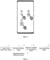
- the schematic diagram of the appointed position and its corresponding appointed direction may be shown in FIG. 2 , which includes eight appointed positions, and each appointed position corresponds to one appointed direction:
- one appointed position may also correspond to multiple appointed directions, which won't be repeated in the embodiment.
- the sliding operation from one appointed position in one of its corresponding appointed directions may be performed once.
- the sliding operation from one appointed position in one of its corresponding appointed directions may be performed at least twice, so as to further ensure a full coverage of the sliding operations on the mobile terminal screen.
- an overlapping region of the multiple sliding operations may be generated.
- An average of the pressure values generated by the at least two sliding operations at one pixel position may be used as the pressure value at the pixel position, so as to make the obtained pressure value more accurate, thereby making a divided sub-region more accurate, and giving the operation comfort level a better representation.
- the pressure value at the pixel position generated by the sliding operation is determined as the average of pressure values generated by the at least two sliding operations at the pixel position.
- step 102 sub-regions are divided.
- a region of the mobile terminal screen may be divided into at least two sub-regions according to the pressure value at each pixel position, and each of the at least two sub-region corresponds to a pressure value range.
- pixels with pressure values greater than A1 at pixel positions thereof may be divided into one sub-region, marked as sub-region 1; pixels with pressure values greater than A2 and less than A1 thereof may be divided into one sub-region, marked as sub-region 2; and pixels with pressure values greater than A3 and less than A2 thereof may be divided into one sub-region, marked as sub-region 3.
- the screen region is divided into three sub-regions. It could be understood that the operation comfort level of the sub-region 1 is the highest, the operation comfort level of the sub-region 2 is the second, and the operation comfort level of the sub-region3 is the lowest.
- the individual differences of the users may be better met to determine differentiated sub-regions, which effectively reduces the difficulty of the single-hand operation.
- the sliding operation may be affected, so that the determined sub-regions may also be changed, and therefore operation requirements of the user may be well adapted and the convenience of the single-hand operation may be improved.
- step 103 a layout of an icon is determined.
- the layout of the icon of each system interface may be determined according to a position of each divided sub-region on the screen.
- the icon on the system interface of the mobile terminal may be laid out as far as possible in a sub-region with the highest operation comfort level. If an area of the sub-region with the highest operation comfort level is insufficient to lay out the icon, the icon may further be laid out in a sub-region with a second operation comfort level, and so on, until all the icons are laid out on the system interface.
- a reduced or enlarged ratio of the icon may further be determined to meet layout requirements of the icon.
- step 102' may be included in the embodiment.
- step 102' a reduced or enlarged ratio of the icon is determined.
- the reduced or enlarged ratio of the icon on each system interface may be determined according to an area of each divided sub-region.
- a reduced ratio of the icons may be determined in order to lay out the icons in a sub-region with a higher operation comfort level (whose area may be a sum of areas of many sub-regions with higher operation comfort levels, for example, the sum of the areas of a sub-region with the highest operation comfort level and a sub-region with a second highest operation comfort level) as much as possible.
- an enlarged ratio of the icons may be determined. By displaying larger icons, the convenience of the operation may be improved much more.
- FIG. 4(a) is a schematic diagram of a layout of an icon according to a system default interface
- FIG. 4(b) is a schematic diagram of a layout of an icon on a system interface after icons are reduced according to the embodiment.
- the layout of icon on the system interface is not limited to that shown in FIG. 4 (b) .
- the layout of the icon may also be changed in the case that distributions of at least two determined sub-regions with different operation comfort levels on the screen are different.
- the step 103 may include: determining a layout of a reduced or enlarged icon on each system interface according to the position of each divided sub-region on the screen.
- the embodiment may further include step 104.
- this step is executed after the step 103, which is an example.
- the step 104 is not limited to be executed after the step 103.
- step 104 a value of an operating parameter is determined.
- a value corresponding to at least one operating parameter for each divided sub-region may be determined, and the operating parameter is a parameter for identifying a screen operation.
- different values of different operating parameters may be determined for sub-regions with different operation comfort levels, so that the operation may also be successfully implemented even in a sub-region with a lower comfort level, thereby ensuring the convenience and accuracy of the operation.
- the at least one operating parameter may include but not limited to at least one of: a hot region for triggering an icon, a click control region for a control on a framework of the system interface, a hot region for triggering a slide, and a magnitude of force for triggering a slide.
- the hot region for triggering an icon is a region for triggering the icon by clicking;
- the click control region for a control is a region for implementing control on the control by clicking;
- the hot region for triggering a slide is a minimum area for identifying the slide; and the magnitude of force for triggering a slide is a minimum pressure for identifying the slide.
- values of the hot region for triggering an icon, the click control region for a control on a framework of the system interface, the hot region for triggering a slide, and the magnitude of force for triggering a slide in each sub-region may be determined to ensure the icon is triggered accurately, the control on the framework of the system interface is controlled accurately and an execution of the sliding operation is performed successfully.
- FIG. 5 is a schematic diagram of values of the hot regions for triggering an icon respectively determined for the sub-region 1, the sub-region 2 and the sub-region 3 shown in FIG. 3 .
- a determined size of the hot region for triggering an icon corresponding to the sub-region 1 may be the size of the icon shown in 1 (In FIG.
- a size of the hot region for triggering an icon corresponding to the sub-region 2 may be the size of the icon shown in 2 (an area of a hot region for triggering an icon corresponding to the sub-region 2 is greater than that of the icon, for example, assuming that the icon is a square, a side length of the hot region for triggering an icon corresponding to the sub-region 2 may be 1mm longer than that of the icon), a size of the hot region for triggering an icon corresponding to the sub-region 3 may be the size of the icon shown in 3 (an area of a hot region for triggering an icon corresponding to the sub-region 3 increases further, a side length of the hot region for triggering an icon corresponding to the sub-region 3 is 2mm longer than that of the icon).
- an area of the hot region for triggering an icon gradually increases with the decrease of the operation comfort level, so that the icon triggering may be realized easily for the sub-region with the lower operation comfort level through an hot region for triggering an icon with a larger area.
- the determined layout of the icon and the values of the operating parameters may be directly applied to a setting of the default system interface of the mobile terminal, and an interface corresponding to an updated setting of the system interface may be displayed.
- the determined layout of the icon and the values of the operating parameters may also be saved, or the updated setting of the system interface may be saved, so as to realize a display of a new system interface later.
- the determined layout of the icon and the values of the operating parameters may also be saved or the updated setting of the system interface may be saved, so that, after an exit of the system interface applying the determined layout of the icon and the values of the operating parameters, the user may enter it again.
- the default system interface may automatically apply the determined layout of the icon and the values of the operating parameters to generate a new setting of the system interface and realize the display of a new system interface. If the updated setting of the system interface is saved, the display of the new system interface may be implemented directly according to the updated setting of the system interface.
- the execution of the steps 101 to 104 may be triggered in any way at any time when the mobile terminal is turned on.
- the steps 101 to 104 may be, but not limited to, automatically executed during an initial startup of a new mobile terminal.
- an individual customized setting of an interactive interface for a user to choose may be determined according to a guided sliding operation and through a system calculation.
- a user may choose to apply the determined layout of the icon and the values of the operating parameters directly, and after it is applied, the default system interface may automatically adapt the determined layout of the icon and the values of the operating parameters, so as to realize the display of the new system interface.
- a user may exit the interface applying the determined layout of the icon and the values of the operating parameters in any way. For example, it may be, but not limited to, implemented in the following way: by displaying a prompt message in a notification bar of the mobile terminal, the default system interface may be returned with one key when the prompt message is closed.
- the interface applying the determined layout of the icon and the values of the operating parameters may also be re-entered, which may be triggered in any way.
- the prompt message may also be displayed after the default system interface is returned, the interface applying the determined layout of the icon and the values of the operating parameters may be re-entered by clicking the prompt message.
- the embodiment 2 of the present invention provides an apparatus for setting a system interface of a mobile terminal, a structure of the apparatus may be shown as FIG. 6 , including:
- the apparatus also includes a reduced or enlarged ratio determining module 14, configured to determine a reduced or enlarged ratio of the icon on each system interface according to an area of each divided sub-region.
- the layout determining module 13 is specifically configured to determine a layout of a reduced or enlarged icon on each system interface according to a position of the each divided sub-region on the screen.
- the pressure value determining module 11 is configured to determine a pressure value on the pixel position generated by the sliding operation, when at least two sliding operations pass a same pixel position, as an average of pressure values generated by the at least two sliding operations at the pixel position.
- the apparatus also includes an operating parameter determining module 15, configured to determine a value corresponding to at least one operating parameter for each divided sub-region, wherein the operating parameter is a parameter for identifying a screen operation.
- the embodiments of the present invention provide a following device and medium.
- the embodiment 3 of the present invention provides a device for setting a system interface of a mobile terminal, a structure of the device may be shown as FIG. 7 , including: a memory 21, a processor 22 and a computer program stored on the memory.
- a computer program is performed by the processor 22, the steps in the method described in the embodiment 1 of the present invention are implemented.
- the processor 22 may specifically include Central Processing Unit (CPU), Application Specific Integrated Circuit (ASIC), and the processor 22 may be one or more integrated circuits for controlling program execution, a hardware circuit developed using Field Programmable Gate Arrays (FPGA), or a baseband processor.
- CPU Central Processing Unit
- ASIC Application Specific Integrated Circuit
- FPGA Field Programmable Gate Arrays
- the processor 22 may include at least one processing core.
- the memory 21 may include a Read Only Memory (ROM), a Random Access Memory (RAM) and a disk storage.
- the memory 21 is used to store data required for the operation of at least one processor 22.
- the number of memories may be one or more.
- the embodiment 4 of the present invention provides a non-transitory computer storage medium, the computer storage medium stores an executable program, and the executable program is performed by a processor to implement the steps in the method described in the embodiment 1 of the present invention.
- the computer storage medium may include: Universal Serial Bus (USB) flash drive, removable hard disk, Read Only Memory (ROM), Random Access Memory (RAM), magnetic disk or optical disk and other storage medium that may store program codes.
- USB Universal Serial Bus
- ROM Read Only Memory
- RAM Random Access Memory
- magnetic disk or optical disk and other storage medium that may store program codes.
- the apparatus and method in the embodiments of the present invention may be implemented in other ways.
- the embodiments of the apparatus described above are only schematic, for example, the units or the division of the units are just the division of logical functions, there may be other ways to divide the units in actual implementation, such as multiple units or components may be combined or integrated into another system, or some features may be ignored or not performed.
- a coupling or a direct coupling or a communication connection shown or discussed between each other may be an indirect coupling or a communication connection through some interfaces, devices or units, or in the form of electricity or in other forms.
- Each functional unit in the embodiments of the present invention may be integrated in a processing unit, or each unit may be a separate physical module.
- the integrated element may be stored in a computer-readable storage medium if being achieved in the form of a software function element and sold or used as a standalone product.
- all or part of the technical solutions in the embodiments of the present invention may be embodied in the form of a software product that is stored in a storage medium, including multiple instructions used to cause a computer device, such as a personal computer, a server, or a network device, a processor and the like, to implement all or part of the steps of the method described in various embodiments of the present invention.
- the abovementioned storage medium includes: various medium capable of storing a program code, such as a universal serial bus flash drive, a Read Only Memory (ROM), a Random Access Memory (RAM), a mobile hard disk, a magnetic disk or an optical disc.
- a method, a system or a computer program product may be provided.
- forms of hardware embodiments, full software embodiments or embodiments integrating software and hardware may be adopted in the present invention.
- a form of the computer program product implemented on at least one computer available storage media including, but not limited to, a disk memory, a Compact Disc Read-Only Memory (CD-ROM), an optical memory and the like
- computer available program codes may be adopted in the present invention.
- each flow and/or block in the flowcharts and/or the block diagrams and a combination of the flows and/or the blocks in the flowcharts and/or the block diagrams may be realized by computer program instructions.
- These computer program instructions may be provided for a general computer, a dedicated computer, an embedded processor or processors of other programmable data processing devices to generate a machine, so that an apparatus for realizing functions assigned in at least one flow of the flowcharts and/or at least one block of the block diagrams is generated via instructions executed by the computers or the processors of the other programmable data processing devices.
- These computer program instructions may also be stored in a computer readable memory capable of guiding the computers or the other programmable data processing devices to work in a specific mode, so that a manufactured product including an instruction apparatus is generated via the instructions stored in the computer readable memory, and the instruction apparatus realizes the functions assigned in at least one flow of the flowcharts and/or at least one block of the block diagrams.
- These computer program instructions may also be loaded to the computers or the other programmable data processing devices, so that processing realized by the computers is generated by executing a series of operation steps on the computers or the other programmable devices, and therefore the instructions executed on the computers or the other programmable devices provide steps of realizing the functions assigned in at least one flow of the flowcharts and/or at least one block of the block diagrams.
Landscapes
- Engineering & Computer Science (AREA)
- General Engineering & Computer Science (AREA)
- Theoretical Computer Science (AREA)
- Human Computer Interaction (AREA)
- Physics & Mathematics (AREA)
- General Physics & Mathematics (AREA)
- User Interface Of Digital Computer (AREA)
- Telephone Function (AREA)
- Digital Computer Display Output (AREA)
Abstract
Description
- The present invention claims priority to Chinese Patent Application No.
201810726713.4, filed on July 4, 2018 - The present invention relates to a technical field of a mobile terminal, in particular to a method, an apparatus and a device for setting a system interface of a mobile terminal, and a medium.
- At present, a touch screen is used on most of mobile phones, tablet computers and other mobile terminals. As the increases of a size of the touch screen, the difficulty of a single-hand operation is also increased under the existing system interface. When a mobile terminal is held by a user in single-hand, due to the influence of individual differences between users, such as a size of a hand, a grip position or other factors, a system interface interaction between the user and a screen of the mobile terminal varies from person to person, and the difficulty of the single-hand operation for each user is also not exactly the same. However, at present, there is no method that reduces the difficulty of the single-hand operation for the differences between the users.
- Embodiments of the present invention provide a method, an apparatus and a device for setting a system interface of a mobile terminal, and a medium, so as to solve problems that it is unable to effectively reduce the difficulty of a single-hand operation for different users.
- The present invention provides a method for setting a system interface of a mobile terminal, including:
- determining a pressure value generated by a sliding operation at each pixel position on a mobile terminal screen, wherein the sliding operation includes at least one sliding operation performed on the mobile terminal screen in a single-hand operation mode, for each appointed position and according to each appointed direction which corresponds to the appointed position;
- dividing a region of the mobile terminal screen into at least two sub-regions according to the pressure value at each pixel position, wherein each of the at least two sub-regions corresponds to a pressure value range; and
- determining a layout of an icon of each system interface according to a position of each divided sub-region on the screen.
- According to the solutions provided by the present invention, for each user, the pressure value generated at each pixel position on the mobile terminal screen may be determined after performing the sliding operation in the single-hand operation mode, the sub-regions may be divided according to the pressure value of each pixel position, and thereby, for each system interface, the layout of the icon may be determined according to the position of each divided sub-region. Thus, the sub-regions may be divided targetedly according to characteristics of the sliding operation of each user, so that an icon position laid out for each system interface, according to the divided sub-regions, may be more adaptive to operation requirements of the user and may targetedly reduce operation difficulty of the user.
- In addition, the method further includes:
- determining a reduced or enlarged ratio of the icon on each system interface according to an area of each divided sub-region; and
- the determining a layout of an icon of each system interface according to a position of each divided sub-region on the screen, includes:
- determining a layout of a reduced or enlarged icon on each system interface according to the position of each divided sub-region on the screen.
- Before laying out the icon, the reduced or enlarged ratio of the icon may be further determined for each system interface according to the area of each divided sub-region, and thereby the reduced or enlarged icon may be laid out. By reducing a size of the icon, the icon may be laid out at a sub-region with a highest operation comfort level as far as possible, which improves the convenience of an operation. By enlarging a size of the icon, a bigger icon may be displayed on the system interface, which is capable of improving the convenience of the operation and reducing the operation difficulty.
- Further, when at least two sliding operations pass a same pixel position, a pressure value on the pixel position generated by the sliding operation is determined as an average of pressure values generated by the at least two sliding operations at the pixel position.
- In solutions according to the present invention, if there are at least two sliding operations performed at a same pixel position, the average of the pressure values generated by the at least two sliding operations at the pixel position may be taken as the pressure value at the pixel position, which makes the obtained pressure value more accurate, and thereby makes a division of the sub-regions more accurate.
- Further, the method further includes: determining a value corresponding to at least one operating parameter for each divided sub-region, and the operating parameter is a parameter for identifying a screen operation.
- In the solutions according to the present invention, values of different operating parameters may be determined for sub-regions with different operation comfort levels, so that even in a sub-region with a lower operation comfort level, the operation may also be successfully implemented, which ensures the convenience and accuracy of the operation.
- Further, the at least one operating parameter includes at least one of the followings: a hot region for triggering an icon, a click control region for a control on a framework of the system interface, a hot region for triggering a slide, and a magnitude of force for triggering a slide;
the hot region for triggering an icon is a region for triggering the icon by clicking; the click control region for a control is a region for implementing control on the control by clicking; the hot region for triggering a slide is a minimum area for identifying the slide; and the magnitude of force for triggering a slide is a minimum pressure for identifying a slide. - In the solutions according to the present invention, in order to ensure the icon is triggered accurately, the control on the framework of the system interface is controlled accurately and the sliding operation is implemented successfully, values of the hot region for triggering an icon, the click control region for a control on a framework of the system interface, the hot region for triggering a slide and the magnitude of force for triggering a slide in each sub-region may be determined.
- The present invention further provides an apparatus for setting a system interface of a mobile terminal, including:
- a pressure value determining module, configured to determine a pressure value generated by a sliding operation at each pixel position on a mobile terminal screen, wherein the sliding operation includes at least one sliding operation performed on the mobile terminal screen in a single-hand operation mode, for each appointed position and according to each appointed direction which corresponds to the appointed position;
- a sub-region dividing module, configured to divide a region of the mobile terminal screen into at least two sub-regions according to the pressure value at each pixel position, wherein each of the at least two sub-region corresponds to a pressure value range; and
- a layout determining module, configured to determine a layout of an icon of each system interface according to a position of each divided sub-region on the screen.
- The apparatus further includes a reduced or enlarged ratio determining module, configured to determine a reduced or enlarged ratio of the icon on each system interface according to an area of each divided sub-region; and
the layout determining module is specifically configured to determine a layout of a reduced or enlarged icon on each system interface according to the position of each divided sub-region on the screen. - The pressure value determining module is configured to determine a pressure value on the pixel position generated by the sliding operation, when at least two sliding operations pass a same pixel position, as an average of pressure values generated by the at least two sliding operations at the pixel position.
- The apparatus further includes an operating parameter determining module, configured to determine a value corresponding to at least one operating parameter for each divided sub-region, and the operating parameter is a parameter for identifying a screen operation.
- The present invention also provides a non-transitory computer storage medium, the computer storage medium stores an executable program, and the executable program is performed by a processor to implement the steps in the above method.
- The present invention also provides a device for setting a system interface of a mobile terminal, including a memory, a processor, and a computer program stored on the memory, and the computer program is performed by the processor, the steps in the above method are implemented.
- In order to describe the technical solutions in the embodiments of the present invention more clearly, a brief introduction on the drawings needed in the description of the embodiments is given below. Obviously, the drawings in the description below are only some embodiments of the present invention, based on which other drawings may also be obtained by those of ordinary skill in the art without any inventive efforts.
-
FIG. 1 is a flowchart of a method for setting a system interface of a mobile terminal according toembodiment 1 of the present invention; -
FIG. 2 is a schematic diagram of an appointed position and an appointed direction according toembodiment 1 of the present invention; -
FIG. 3 is a schematic diagram of a sub-region division according toembodiment 1 of the present invention; -
FIG. 4 (a) is a schematic diagram of a layout of an icon according to a system default interface; -
FIG. 4 (b) is a schematic diagram of a layout of an icon according toembodiment 1 of the present invention; -
FIG. 5 is a schematic diagram of sizes of hot regions for triggering an icon for different sub-regions according toembodiment 1 of the present invention; -
FIG. 6 is a schematic structural diagram of an apparatus for setting a system interface of a mobile terminal according toembodiment 2 of the present invention; and -
FIG. 7 is a schematic structural diagram of a device for setting a system interface of a mobile terminal according toembodiment 3 of the present invention. - In order to make the purposes, technical solutions and advantages of the present invention clearer, the specific embodiments of the present invention will be further described below in detail in combination with the drawings. Apparently, the described embodiments are only a part, but not all, of the embodiments of the present invention. All of the other embodiments that are obtained by those of ordinary skill in the art based on the embodiments in the present invention without any inventive efforts fall into the scope protected by the present invention.
- It should be noted that the terms "including" and "comprising" and any of their variations in the description and claims and the drawings of the present invention are intended to cover non-exclusive inclusions, for example, a process, method, system, product, or device that includes a series of steps or units need not be limited to those explicitly listed, instead it may include other steps or units not explicitly listed or inherent to this process, method, product or device.
- The
embodiment 1 of the present invention provides a method for setting a system interface of a mobile terminal. A flowchart of steps of the method, as shown inFIG. 1 , includes the following steps. - In
step 101, a pressure value is determined. - In general, the more a region is suitable for performing an operation, the greater the pressure value generated when a user performs a sliding operation is, due to the convenience of the operation. Therefore, in the embodiment, an operation comfort level is represented by the pressure value generated when the sliding operation is performed. It may be appreciated that the higher the pressure value is, the higher the operation comfort level is.
- In this step, the pressure value generated by the sliding operation at each pixel position on a mobile terminal screen may be determined, and the sliding operation includes at least one sliding operation performed on the mobile terminal screen in a single-hand operation mode, for each appointed position and according to each appointed direction which corresponds to the appointed position.
- Specifically, the user may be instructed to perform the at least one sliding operation from each appointed position in each appointed direction corresponding to each appointed position on the mobile terminal screen in the single-hand operation mode. By setting the appointed position and a corresponding appointed direction, the sliding operation of the user may be performed on an entire mobile terminal screen as much as possible, and thus the pressure value at each pixel position may be determined when the sliding operation is performed on the mobile terminal screen.
- The setting for each appointed position, and for each appointed direction corresponding to each appointed position, may be arbitrary. Preferably, in order to ensure that a user may perform a sliding operation at each pixel position while trying to reduce the number of sliding operations of the user, the schematic diagram of the appointed position and its corresponding appointed direction may be shown in
FIG. 2 , which includes eight appointed positions, and each appointed position corresponds to one appointed direction: - the appointed position being a midpoint of an upper edge of the screen, and its corresponding appointed direction being downward;
- the appointed position being a midpoint on a bottom edge of the screen, and its corresponding appointed direction being upward;
- the appointed position being a midpoint of a left edge of the screen, and its corresponding appointed direction being rightward;
- the appointed position being a midpoint of a right edge of the screen, and its corresponding appointed direction being leftward;
- the appointed position being an upper left corner of the screen, and its corresponding appointed direction being toward a lower right corner;
- the appointed position being a lower left corner of the screen, and its corresponding appointed direction being toward an upper right corner;
- the appointed position being an upper right corner of the screen, and its corresponding appointed direction being toward a lower left corner; and
- the appointed position being a lower right corner of the screen, and its corresponding appointed direction being toward an upper left corner.
- When the schematic diagram of the appointed position and the appointed direction are as shown in
FIG. 2 , it is required to respectively perform the at least one sliding operation for each appointed position in its corresponding appointed direction, that is, at least eight sliding operations shall be performed. Of course, one appointed position may also correspond to multiple appointed directions, which won't be repeated in the embodiment. - The sliding operation from one appointed position in one of its corresponding appointed directions may be performed once. Preferably, the sliding operation from one appointed position in one of its corresponding appointed directions may be performed at least twice, so as to further ensure a full coverage of the sliding operations on the mobile terminal screen.
- If multiple sliding operations are performed from one appointed position in one of its corresponding appointed directions, an overlapping region of the multiple sliding operations may be generated. An average of the pressure values generated by the at least two sliding operations at one pixel position may be used as the pressure value at the pixel position, so as to make the obtained pressure value more accurate, thereby making a divided sub-region more accurate, and giving the operation comfort level a better representation.
- Of course, even if the sliding operation is performed once from one appointed position in one of its corresponding appointed directions, multiple sliding operations from multiple appointed positions in their corresponding appointed directions may also generate the overlapping region. In this situation, the average of the pressure values generated by the multiple sliding operations at one pixel position may also be used as the pressure value at the pixel position.
- Specifically, when the at least two sliding operations pass a same pixel position, the pressure value at the pixel position generated by the sliding operation is determined as the average of pressure values generated by the at least two sliding operations at the pixel position.
- In
step 102, sub-regions are divided. - In this step, a region of the mobile terminal screen may be divided into at least two sub-regions according to the pressure value at each pixel position, and each of the at least two sub-region corresponds to a pressure value range.
- For example, as shown in
FIG. 3 , pixels with pressure values greater than A1 at pixel positions thereof may be divided into one sub-region, marked assub-region 1; pixels with pressure values greater than A2 and less than A1 thereof may be divided into one sub-region, marked assub-region 2; and pixels with pressure values greater than A3 and less than A2 thereof may be divided into one sub-region, marked assub-region 3. Thus, the screen region is divided into three sub-regions. It could be understood that the operation comfort level of thesub-region 1 is the highest, the operation comfort level of thesub-region 2 is the second, and the operation comfort level of the sub-region3 is the lowest. - Due to the individual differences of the users, performances of the sliding operations are different, so that the sub-regions determined by each user may be different. And determined sub-regions may also be different after a same user performing sliding operations with the left hand and the right hand respectively. Therefore, in the solutions according to the embodiment, the individual differences of the users may be better met to determine differentiated sub-regions, which effectively reduces the difficulty of the single-hand operation. Meanwhile, as for a sliding operation performed by a same hand of a same user, if a size of the mobile terminal and/or a size of the screen is different, the sliding operation may be affected, so that the determined sub-regions may also be changed, and therefore operation requirements of the user may be well adapted and the convenience of the single-hand operation may be improved.
- In
step 103, a layout of an icon is determined. - In this step, the layout of the icon of each system interface may be determined according to a position of each divided sub-region on the screen.
- Specifically, as for each system interface, the icon on the system interface of the mobile terminal may be laid out as far as possible in a sub-region with the highest operation comfort level. If an area of the sub-region with the highest operation comfort level is insufficient to lay out the icon, the icon may further be laid out in a sub-region with a second operation comfort level, and so on, until all the icons are laid out on the system interface.
- Preferably, after the
step 102 and before thestep 103, a reduced or enlarged ratio of the icon may further be determined to meet layout requirements of the icon. Further, step 102' may be included in the embodiment. - In step 102', a reduced or enlarged ratio of the icon is determined.
- In this step, the reduced or enlarged ratio of the icon on each system interface may be determined according to an area of each divided sub-region.
- For example, on one system interface, if there are larger quantity of icons need to be displayed, a reduced ratio of the icons may be determined in order to lay out the icons in a sub-region with a higher operation comfort level (whose area may be a sum of areas of many sub-regions with higher operation comfort levels, for example, the sum of the areas of a sub-region with the highest operation comfort level and a sub-region with a second highest operation comfort level) as much as possible. For another example, on another system interface, if there are smaller quantity of icons need to be displayed, an enlarged ratio of the icons may be determined. By displaying larger icons, the convenience of the operation may be improved much more.
-
FIG. 4(a) is a schematic diagram of a layout of an icon according to a system default interface, andFIG. 4(b) is a schematic diagram of a layout of an icon on a system interface after icons are reduced according to the embodiment. Of course, the layout of icon on the system interface is not limited to that shown inFIG. 4 (b) . The layout of the icon may also be changed in the case that distributions of at least two determined sub-regions with different operation comfort levels on the screen are different. - If the step 102' has been performed, the
step 103 may include: determining a layout of a reduced or enlarged icon on each system interface according to the position of each divided sub-region on the screen. - Further, after the
step 102, the embodiment may further includestep 104. InFIG. 1 , this step is executed after thestep 103, which is an example. Thestep 104 is not limited to be executed after thestep 103. - In
step 104, a value of an operating parameter is determined. - In this step, a value corresponding to at least one operating parameter for each divided sub-region may be determined, and the operating parameter is a parameter for identifying a screen operation. Then different values of different operating parameters may be determined for sub-regions with different operation comfort levels, so that the operation may also be successfully implemented even in a sub-region with a lower comfort level, thereby ensuring the convenience and accuracy of the operation.
- Specifically, the at least one operating parameter may include but not limited to at least one of: a hot region for triggering an icon, a click control region for a control on a framework of the system interface, a hot region for triggering a slide, and a magnitude of force for triggering a slide.
- The hot region for triggering an icon is a region for triggering the icon by clicking; the click control region for a control is a region for implementing control on the control by clicking; the hot region for triggering a slide is a minimum area for identifying the slide; and the magnitude of force for triggering a slide is a minimum pressure for identifying the slide.
- Preferably, values of the hot region for triggering an icon, the click control region for a control on a framework of the system interface, the hot region for triggering a slide, and the magnitude of force for triggering a slide in each sub-region may be determined to ensure the icon is triggered accurately, the control on the framework of the system interface is controlled accurately and an execution of the sliding operation is performed successfully.
- The determining a value of the hot region for triggering an icon for each sub-region may be explained below, as an example.
FIG. 5 is a schematic diagram of values of the hot regions for triggering an icon respectively determined for thesub-region 1, thesub-region 2 and thesub-region 3 shown inFIG. 3 . A determined size of the hot region for triggering an icon corresponding to thesub-region 1 may be the size of the icon shown in ① (InFIG. 5 , the values of the hot regions for triggering an icon corresponding to three sub-regions are illustrated by taking the icons named item one as an example), a size of the hot region for triggering an icon corresponding to thesub-region 2 may be the size of the icon shown in ② (an area of a hot region for triggering an icon corresponding to thesub-region 2 is greater than that of the icon, for example, assuming that the icon is a square, a side length of the hot region for triggering an icon corresponding to thesub-region 2 may be 1mm longer than that of the icon), a size of the hot region for triggering an icon corresponding to thesub-region 3 may be the size of the icon shown in ③ (an area of a hot region for triggering an icon corresponding to thesub-region 3 increases further, a side length of the hot region for triggering an icon corresponding to thesub-region 3 is 2mm longer than that of the icon). As shown inFIG. 5 , an area of the hot region for triggering an icon gradually increases with the decrease of the operation comfort level, so that the icon triggering may be realized easily for the sub-region with the lower operation comfort level through an hot region for triggering an icon with a larger area. - It should be noted that, after the execution of the
step 103 or thestep 104, the determined layout of the icon and the values of the operating parameters may be directly applied to a setting of the default system interface of the mobile terminal, and an interface corresponding to an updated setting of the system interface may be displayed. The determined layout of the icon and the values of the operating parameters may also be saved, or the updated setting of the system interface may be saved, so as to realize a display of a new system interface later. - Of course, after the interface corresponding to the updated setting of the system interface is displayed, the determined layout of the icon and the values of the operating parameters may also be saved or the updated setting of the system interface may be saved, so that, after an exit of the system interface applying the determined layout of the icon and the values of the operating parameters, the user may enter it again.
- If the determined layout of the icon and the values of the operating parameters are saved, when there is a need to enter the interface applying the determined layout of the icon and the values of the operating parameters, the default system interface may automatically apply the determined layout of the icon and the values of the operating parameters to generate a new setting of the system interface and realize the display of a new system interface. If the updated setting of the system interface is saved, the display of the new system interface may be implemented directly according to the updated setting of the system interface.
- The execution of the
steps 101 to 104 may be triggered in any way at any time when the mobile terminal is turned on. For example, thesteps 101 to 104 may be, but not limited to, automatically executed during an initial startup of a new mobile terminal. Namely, in a guided interface of the new mobile terminal, an individual customized setting of an interactive interface for a user to choose may be determined according to a guided sliding operation and through a system calculation. A user may choose to apply the determined layout of the icon and the values of the operating parameters directly, and after it is applied, the default system interface may automatically adapt the determined layout of the icon and the values of the operating parameters, so as to realize the display of the new system interface. - A user may exit the interface applying the determined layout of the icon and the values of the operating parameters in any way. For example, it may be, but not limited to, implemented in the following way: by displaying a prompt message in a notification bar of the mobile terminal, the default system interface may be returned with one key when the prompt message is closed.
- Of course, the interface applying the determined layout of the icon and the values of the operating parameters may also be re-entered, which may be triggered in any way. For example, the prompt message may also be displayed after the default system interface is returned, the interface applying the determined layout of the icon and the values of the operating parameters may be re-entered by clicking the prompt message.
- Based on a same inventive concept as the
embodiment 1, a following apparatus is provided. - The
embodiment 2 of the present invention provides an apparatus for setting a system interface of a mobile terminal, a structure of the apparatus may be shown asFIG. 6 , including: - a pressure
value determining module 11, configured to determine a pressure value generated by a sliding operation at each pixel position on a mobile terminal screen, wherein the sliding operation includes at least one sliding operation performed on the mobile terminal screen in a single-hand operation mode, for each appointed position and according to each appointed direction which corresponds to the appointed position; - a
sub-region dividing module 12, configured to divide a region of the mobile terminal screen into at least two sub-regions according to the pressure value at each pixel position, wherein each of the at least sub-regions corresponds to a pressure value range; and - a
layout determining module 13, configured to determine a layout of an icon of each system interface according to a position of each divided sub-region on the screen. - The apparatus also includes a reduced or enlarged
ratio determining module 14, configured to determine a reduced or enlarged ratio of the icon on each system interface according to an area of each divided sub-region. - The
layout determining module 13 is specifically configured to determine a layout of a reduced or enlarged icon on each system interface according to a position of the each divided sub-region on the screen. - The pressure
value determining module 11 is configured to determine a pressure value on the pixel position generated by the sliding operation, when at least two sliding operations pass a same pixel position, as an average of pressure values generated by the at least two sliding operations at the pixel position. - The apparatus also includes an operating
parameter determining module 15, configured to determine a value corresponding to at least one operating parameter for each divided sub-region, wherein the operating parameter is a parameter for identifying a screen operation. - Based on the same inventive concept, the embodiments of the present invention provide a following device and medium.
- The
embodiment 3 of the present invention provides a device for setting a system interface of a mobile terminal, a structure of the device may be shown asFIG. 7 , including: amemory 21, aprocessor 22 and a computer program stored on the memory. When the computer program is performed by theprocessor 22, the steps in the method described in theembodiment 1 of the present invention are implemented. - Optionally, the
processor 22 may specifically include Central Processing Unit (CPU), Application Specific Integrated Circuit (ASIC), and theprocessor 22 may be one or more integrated circuits for controlling program execution, a hardware circuit developed using Field Programmable Gate Arrays (FPGA), or a baseband processor. - Optionally, the
processor 22 may include at least one processing core. - Optionally, the
memory 21 may include a Read Only Memory (ROM), a Random Access Memory (RAM) and a disk storage. Thememory 21 is used to store data required for the operation of at least oneprocessor 22. The number of memories may be one or more. - The embodiment 4 of the present invention provides a non-transitory computer storage medium, the computer storage medium stores an executable program, and the executable program is performed by a processor to implement the steps in the method described in the
embodiment 1 of the present invention. - In the specific implementation process, the computer storage medium may include: Universal Serial Bus (USB) flash drive, removable hard disk, Read Only Memory (ROM), Random Access Memory (RAM), magnetic disk or optical disk and other storage medium that may store program codes.
- It should be understood that the apparatus and method in the embodiments of the present invention may be implemented in other ways. For example, the embodiments of the apparatus described above are only schematic, for example, the units or the division of the units are just the division of logical functions, there may be other ways to divide the units in actual implementation, such as multiple units or components may be combined or integrated into another system, or some features may be ignored or not performed. On the other hand, a coupling or a direct coupling or a communication connection shown or discussed between each other may be an indirect coupling or a communication connection through some interfaces, devices or units, or in the form of electricity or in other forms.
- Each functional unit in the embodiments of the present invention may be integrated in a processing unit, or each unit may be a separate physical module.
- The integrated element may be stored in a computer-readable storage medium if being achieved in the form of a software function element and sold or used as a standalone product. Based on such understanding, all or part of the technical solutions in the embodiments of the present invention may be embodied in the form of a software product that is stored in a storage medium, including multiple instructions used to cause a computer device, such as a personal computer, a server, or a network device, a processor and the like, to implement all or part of the steps of the method described in various embodiments of the present invention. The abovementioned storage medium includes: various medium capable of storing a program code, such as a universal serial bus flash drive, a Read Only Memory (ROM), a Random Access Memory (RAM), a mobile hard disk, a magnetic disk or an optical disc.
- Those skilled in the art should understand that, in the embodiments of the present invention, a method, a system or a computer program product may be provided. Thus, forms of hardware embodiments, full software embodiments or embodiments integrating software and hardware may be adopted in the present invention. Moreover, a form of the computer program product implemented on at least one computer available storage media (including, but not limited to, a disk memory, a Compact Disc Read-Only Memory (CD-ROM), an optical memory and the like) containing computer available program codes may be adopted in the present invention.
- The present invention is described with reference to flowcharts and/or block diagrams of the method, the device (system) and the computer program product according to the embodiments of the present invention. It should be understood that each flow and/or block in the flowcharts and/or the block diagrams and a combination of the flows and/or the blocks in the flowcharts and/or the block diagrams may be realized by computer program instructions. These computer program instructions may be provided for a general computer, a dedicated computer, an embedded processor or processors of other programmable data processing devices to generate a machine, so that an apparatus for realizing functions assigned in at least one flow of the flowcharts and/or at least one block of the block diagrams is generated via instructions executed by the computers or the processors of the other programmable data processing devices.
- These computer program instructions may also be stored in a computer readable memory capable of guiding the computers or the other programmable data processing devices to work in a specific mode, so that a manufactured product including an instruction apparatus is generated via the instructions stored in the computer readable memory, and the instruction apparatus realizes the functions assigned in at least one flow of the flowcharts and/or at least one block of the block diagrams.
- These computer program instructions may also be loaded to the computers or the other programmable data processing devices, so that processing realized by the computers is generated by executing a series of operation steps on the computers or the other programmable devices, and therefore the instructions executed on the computers or the other programmable devices provide steps of realizing the functions assigned in at least one flow of the flowcharts and/or at least one block of the block diagrams.
- While some embodiments of the present invention have been described, those skilled in the art may make additional changes and modifications to the embodiments once knowing a basic creativity concept. Therefore, the appended claims are intended to be interpreted as including some preferred embodiments and all the changes and modifications falling within the scope of the present invention.
- It is apparent that those skilled in the art may make various modifications and variations to the present invention without departing from the spirit and scope of the present invention. Thus, if such modifications and variations of the present invention fall within the scope of the appended claims and their equivalents, the present invention is also intended to cover the modifications and variations.
Claims (11)
- A method for setting a system interface of a mobile terminal, characterized by, comprising:determining a pressure value generated by a sliding operation at each pixel position on a mobile terminal screen, wherein the sliding operation comprises at least one sliding operation performed on the mobile terminal screen in a single-hand operation mode, for each appointed position and according to each appointed direction which corresponds to the appointed position;dividing a region of the mobile terminal screen into at least two sub-regions according to the pressure value at each pixel position, wherein each of the at least two sub-regions corresponds to a pressure value range; anddetermining a layout of an icon of each system interface according to a position of each divided sub-region on the screen.
- The method of claim 1, further comprising:determining a reduced or enlarged ratio of the icon on each system interface according to an area of each divided sub-region;wherein the determining a layout of an icon of each system interface according to a position of each divided sub-region on the screen, comprises:
determining a layout of a reduced or enlarged icon on each system interface according to the position of each divided sub-region on the screen. - The method of claim 1, wherein when at least two sliding operations pass a same pixel position, a pressure value on the pixel position generated by the sliding operation is determined as an average of pressure values generated by the at least two sliding operations at the pixel position.
- The method of any one of claims 1 to 3, further comprising:
determining a value corresponding to at least one operating parameter for each divided sub-region, wherein the operating parameter is a parameter for identifying a screen operation. - The method of claim 4, wherein the at least one operating parameter comprises at least one of the followings: a hot region for triggering an icon, a click control region for a control on a framework of the system interface, a hot region for triggering a slide, and a magnitude of force for triggering a slide;
wherein the hot region for triggering an icon is a region for triggering the icon by clicking; the click control region for a control is a region for implementing control on the control by clicking; the hot region for triggering a slide is a minimum area for identifying the slide; and the magnitude of force for triggering a slide is a minimum pressure for identifying the slide. - An apparatus for setting a system interface of a mobile terminal, characterized by, comprising:a pressure value determining module, configured to determine a pressure value generated by a sliding operation at each pixel position on a mobile terminal screen, wherein the sliding operation comprises at least one sliding operation performed on the mobile terminal screen in a single-hand operation mode, for each appointed position and according to each appointed direction which corresponds to the appointed position;a sub-region dividing module, configured to divide a region of the mobile terminal screen into at least two sub-regions according to the pressure value at each pixel position, wherein each of the at least sub-regions corresponds to a pressure value range; anda layout determining module, configured to determine a layout of an icon of each system interface according to a position of each divided sub-region on the screen.
- The apparatus of claim 6, further comprising:a reduced or enlarged ratio determining module, configured to determine a reduced or enlarged ratio of the icon on each system interface according to an area of each divided sub-region; andthe layout determining module is specifically configured to determine a layout of a reduced or enlarged icon on each system interface according to the position of each divided sub-region on the screen.
- The apparatus of claim 6, wherein the pressure value determining module is configured to determine a pressure value on the pixel position generated by the sliding operation, when at least two sliding operations pass a same pixel position, as an average of pressure values generated by the at least two sliding operations at the pixel position.
- The apparatus of any one of claims 6 to 8, further comprising:an operating parameter determining module, configured to determine a value corresponding to at least one operating parameter for each divided sub-region,wherein the operating parameter is a parameter for identifying a screen operation.
- A non-transitory computer storage medium, characterized in that the computer storage medium stores an executable program, the executable program is performed by a processor to implement the steps in the method of any one of claims 1 to 5.
- A device for setting a system interface of a mobile terminal, characterized by, comprising:a memory;a processor; anda computer program stored on the memory;wherein the computer program is performed by the processor, the steps in the method of any one of claims 1 to 5 are implemented.
Applications Claiming Priority (2)
| Application Number | Priority Date | Filing Date | Title |
|---|---|---|---|
| CN201810726713.4A CN109164950B (en) | 2018-07-04 | 2018-07-04 | Method, device, medium and equipment for setting system interface of mobile terminal |
| PCT/CN2018/121583 WO2020006988A1 (en) | 2018-07-04 | 2018-12-17 | Method and apparatus for setting interface of mobile terminal system, medium, and device |
Publications (2)
| Publication Number | Publication Date |
|---|---|
| EP3800536A1 true EP3800536A1 (en) | 2021-04-07 |
| EP3800536A4 EP3800536A4 (en) | 2021-08-11 |
Family
ID=64897325
Family Applications (1)
| Application Number | Title | Priority Date | Filing Date |
|---|---|---|---|
| EP18925302.4A Ceased EP3800536A4 (en) | 2018-07-04 | 2018-12-17 | METHOD AND DEVICE FOR SETTING THE INTERFACE OF A MOBILE TERMINAL DEVICE, MEDIUM AND DEVICE |
Country Status (6)
| Country | Link |
|---|---|
| US (1) | US11385791B2 (en) |
| EP (1) | EP3800536A4 (en) |
| JP (1) | JP7085650B2 (en) |
| KR (1) | KR102455639B1 (en) |
| CN (1) | CN109164950B (en) |
| WO (1) | WO2020006988A1 (en) |
Families Citing this family (3)
| Publication number | Priority date | Publication date | Assignee | Title |
|---|---|---|---|---|
| CN111459360A (en) * | 2020-03-31 | 2020-07-28 | Oppo广东移动通信有限公司 | Folder interface switching method and device |
| CN114281424A (en) * | 2020-09-18 | 2022-04-05 | 比亚迪股份有限公司 | Processing method, device, device and storage medium for starting application program |
| CN116507996A (en) * | 2020-09-29 | 2023-07-28 | 乔伊森安全系统收购有限责任公司 | System and method for locking touch position related input area based on force touch display |
Family Cites Families (33)
| Publication number | Priority date | Publication date | Assignee | Title |
|---|---|---|---|---|
| JP5456230B2 (en) * | 2006-10-30 | 2014-03-26 | 京セラ株式会社 | Operation key group layout method and operation key group layout device in portable terminal device |
| KR101285474B1 (en) * | 2009-06-16 | 2013-07-12 | 인텔 코오퍼레이션 | Camera Applications on Handheld Devices |
| US8593418B2 (en) * | 2010-08-08 | 2013-11-26 | Qualcomm Incorporated | Method and system for adjusting display content |
| KR101248562B1 (en) * | 2010-08-25 | 2013-03-28 | 교세라 가부시키가이샤 | Mobile phone and controlling method therefor |
| JP5999374B2 (en) * | 2011-09-05 | 2016-09-28 | 日本電気株式会社 | Portable terminal device, portable terminal control method, and program |
| US8863042B2 (en) * | 2012-01-24 | 2014-10-14 | Charles J. Kulas | Handheld device with touch controls that reconfigure in response to the way a user operates the device |
| KR101907450B1 (en) * | 2012-03-30 | 2018-10-12 | 인포뱅크 주식회사 | Method for Configuring Menu in Portable Terminal |
| US9836213B2 (en) * | 2012-07-27 | 2017-12-05 | Symbol Technologies, Llc | Enhanced user interface for pressure sensitive touch screen |
| US9304683B2 (en) * | 2012-10-10 | 2016-04-05 | Microsoft Technology Licensing, Llc | Arced or slanted soft input panels |
| JP6125811B2 (en) * | 2012-11-22 | 2017-05-10 | 京セラ株式会社 | Electronic device, control method, and control program |
| KR101967765B1 (en) * | 2012-11-28 | 2019-04-10 | 엘지전자 주식회사 | Mobile terminal and method for controlling of the same |
| CN103530049B (en) * | 2013-04-15 | 2017-12-12 | Tcl集团股份有限公司 | A kind of mobile terminal one-handed performance processing method and system with touch-screen |
| KR102127925B1 (en) * | 2013-04-29 | 2020-06-29 | 엘지전자 주식회사 | Mobile terminal and control method thereof |
| CN103309611B (en) * | 2013-05-10 | 2016-07-06 | 北京京东方光电科技有限公司 | The method of a kind of touch screen display control, Apparatus and system |
| DE102013011689B4 (en) * | 2013-07-12 | 2026-01-22 | e.solutions GmbH | Method and apparatus for processing touch signals from a touchscreen, computer program product with program code for carrying out the method, and portable device with the apparatus |
| US9851883B2 (en) * | 2014-02-17 | 2017-12-26 | Xerox Corporation | Method and apparatus for adjusting and moving a user interface for single handed use on an endpoint device |
| CN105468272A (en) * | 2014-09-03 | 2016-04-06 | 中兴通讯股份有限公司 | Interface display method and apparatus |
| US20160132139A1 (en) * | 2014-11-11 | 2016-05-12 | Qualcomm Incorporated | System and Methods for Controlling a Cursor Based on Finger Pressure and Direction |
| CN104571918B (en) | 2015-01-26 | 2018-11-20 | 努比亚技术有限公司 | Terminal one-handed performance interface triggering method and device |
| CN104850341B (en) | 2015-04-24 | 2019-02-26 | 惠州Tcl移动通信有限公司 | A kind of application icon display methods of mobile terminal and mobile terminal |
| CN105630371A (en) | 2015-06-24 | 2016-06-01 | 宇龙计算机通信科技(深圳)有限公司 | Single-hand operation method and apparatus for terminal |
| KR20170006558A (en) * | 2015-07-08 | 2017-01-18 | 엘지전자 주식회사 | Mobile terminal and method for controlling the same |
| CN106445431A (en) * | 2015-08-04 | 2017-02-22 | 中兴通讯股份有限公司 | Terminal operation method and device |
| JP2017054194A (en) * | 2015-09-07 | 2017-03-16 | 富士通株式会社 | Display device, display method and display program |
| CN106557222A (en) * | 2015-09-24 | 2017-04-05 | 中兴通讯股份有限公司 | A kind of screen control method and terminal |
| CN105677173A (en) * | 2015-12-25 | 2016-06-15 | 珠海格力电器股份有限公司 | Single-hand operation mode control method and device of terminal |
| US20170300205A1 (en) * | 2016-04-15 | 2017-10-19 | Qualcomm Incorporated | Method and apparatus for providing dynamically positioned controls |
| US9958979B1 (en) * | 2016-10-31 | 2018-05-01 | International Business Machines Corporation | Web server that renders a web page based on a client pressure profile |
| US9715307B1 (en) * | 2016-10-31 | 2017-07-25 | International Business Machines Corporation | Pressure-sensitive touch screen display and method |
| CN107145294B (en) * | 2017-04-28 | 2020-05-15 | 厦门美图移动科技有限公司 | Method and device for realizing single-hand mode of mobile terminal |
| US20180329605A1 (en) * | 2017-05-15 | 2018-11-15 | Salesforce.Com, Inc. | Arranging graphic elements within a user interface for single handed user touch selections |
| CN107577414A (en) * | 2017-09-07 | 2018-01-12 | 广东欧珀移动通信有限公司 | The method and mobile terminal of split screen display available |
| JP6666525B2 (en) * | 2018-02-08 | 2020-03-13 | 楽天株式会社 | Selection device, selection method, program, and non-temporary computer-readable information recording medium |
-
2018
- 2018-07-04 CN CN201810726713.4A patent/CN109164950B/en active Active
- 2018-12-17 KR KR1020207035085A patent/KR102455639B1/en active Active
- 2018-12-17 WO PCT/CN2018/121583 patent/WO2020006988A1/en not_active Ceased
- 2018-12-17 JP JP2020568534A patent/JP7085650B2/en active Active
- 2018-12-17 EP EP18925302.4A patent/EP3800536A4/en not_active Ceased
-
2020
- 2020-12-15 US US17/122,143 patent/US11385791B2/en active Active
Also Published As
| Publication number | Publication date |
|---|---|
| EP3800536A4 (en) | 2021-08-11 |
| CN109164950A (en) | 2019-01-08 |
| JP2021526272A (en) | 2021-09-30 |
| KR102455639B1 (en) | 2022-10-17 |
| WO2020006988A1 (en) | 2020-01-09 |
| KR20210025005A (en) | 2021-03-08 |
| US11385791B2 (en) | 2022-07-12 |
| CN109164950B (en) | 2020-07-07 |
| JP7085650B2 (en) | 2022-06-16 |
| US20210096744A1 (en) | 2021-04-01 |
Similar Documents
| Publication | Publication Date | Title |
|---|---|---|
| US11768694B2 (en) | Content sharing method, device, terminal and storage medium | |
| US11385791B2 (en) | Method and device for setting layout of icon of system interface of mobile terminal, and medium | |
| EP4016273A1 (en) | Side toolbar display method and device, terminal, and storage medium | |
| EP3690624A1 (en) | Display device and method of controlling the same | |
| WO2020238744A1 (en) | Processing method, device and apparatus for split-screen display, and storage medium | |
| US20160202887A1 (en) | Method for managing application icon and terminal | |
| CN105094508A (en) | Method and apparatus for performing window control on application program of mobile terminal | |
| JP2018503209A (en) | Method for selecting available items in a graphical user interface of a mobile computer system | |
| WO2019047147A1 (en) | Icon moving method and device | |
| US20150286356A1 (en) | Method, apparatus, and terminal device for controlling display of application interface | |
| CN109753215B (en) | Window split-screen display method, device and equipment | |
| US11016788B2 (en) | Application launching method and display device | |
| EP3623928A1 (en) | Page browsing method and device, and electronic apparatus | |
| WO2022121903A1 (en) | Desktop arrangement method and apparatus, and electronic device | |
| CN113648661A (en) | Method and device for processing information in game, electronic equipment and storage medium | |
| CN103455245B (en) | Method and device for regulating area of widget | |
| CN106648281B (en) | A screenshot method and device | |
| EP4060470B1 (en) | Display method and device, and computer readable storage medium | |
| US10943372B2 (en) | GUI display method and apparatus, and terminal device | |
| CN111158620A (en) | Picture display method and device and terminal | |
| CN106126057B (en) | Screen capture method and device and terminal equipment | |
| CN110647263B (en) | Mobile terminal desktop icon moving method, device, medium and equipment | |
| JP7758103B2 (en) | Mathematical formula editing method, mathematical formula editing device, and mathematical formula editing program | |
| CN109032441B (en) | Interface management method, device, equipment and storage medium | |
| CN103927094A (en) | Information processing method, information processing device and electronic device |
Legal Events
| Date | Code | Title | Description |
|---|---|---|---|
| STAA | Information on the status of an ep patent application or granted ep patent |
Free format text: STATUS: THE INTERNATIONAL PUBLICATION HAS BEEN MADE |
|
| PUAI | Public reference made under article 153(3) epc to a published international application that has entered the european phase |
Free format text: ORIGINAL CODE: 0009012 |
|
| STAA | Information on the status of an ep patent application or granted ep patent |
Free format text: STATUS: REQUEST FOR EXAMINATION WAS MADE |
|
| 17P | Request for examination filed |
Effective date: 20210104 |
|
| AK | Designated contracting states |
Kind code of ref document: A1 Designated state(s): AL AT BE BG CH CY CZ DE DK EE ES FI FR GB GR HR HU IE IS IT LI LT LU LV MC MK MT NL NO PL PT RO RS SE SI SK SM TR |
|
| AX | Request for extension of the european patent |
Extension state: BA ME |
|
| A4 | Supplementary search report drawn up and despatched |
Effective date: 20210712 |
|
| RIC1 | Information provided on ipc code assigned before grant |
Ipc: G06F 3/0481 20130101AFI20210706BHEP Ipc: G06F 3/041 20060101ALI20210706BHEP Ipc: G06F 3/0488 20130101ALI20210706BHEP Ipc: G06F 3/0484 20130101ALI20210706BHEP |
|
| DAV | Request for validation of the european patent (deleted) | ||
| DAX | Request for extension of the european patent (deleted) | ||
| STAA | Information on the status of an ep patent application or granted ep patent |
Free format text: STATUS: EXAMINATION IS IN PROGRESS |
|
| 17Q | First examination report despatched |
Effective date: 20220421 |
|
| REG | Reference to a national code |
Ref country code: DE Ref legal event code: R003 |
|
| STAA | Information on the status of an ep patent application or granted ep patent |
Free format text: STATUS: THE APPLICATION HAS BEEN REFUSED |
|
| P01 | Opt-out of the competence of the unified patent court (upc) registered |
Effective date: 20230530 |
|
| 18R | Application refused |
Effective date: 20230403 |