EP3800460A1 - Visual inspector attachment for fiber connector cleaners - Google Patents
Visual inspector attachment for fiber connector cleaners Download PDFInfo
- Publication number
- EP3800460A1 EP3800460A1 EP20197708.9A EP20197708A EP3800460A1 EP 3800460 A1 EP3800460 A1 EP 3800460A1 EP 20197708 A EP20197708 A EP 20197708A EP 3800460 A1 EP3800460 A1 EP 3800460A1
- Authority
- EP
- European Patent Office
- Prior art keywords
- fiber optic
- inspection module
- face
- optic inspection
- mirror
- Prior art date
- Legal status (The legal status is an assumption and is not a legal conclusion. Google has not performed a legal analysis and makes no representation as to the accuracy of the status listed.)
- Granted
Links
Images





Classifications
-
- G—PHYSICS
- G01—MEASURING; TESTING
- G01M—TESTING STATIC OR DYNAMIC BALANCE OF MACHINES OR STRUCTURES; TESTING OF STRUCTURES OR APPARATUS, NOT OTHERWISE PROVIDED FOR
- G01M11/00—Testing of optical apparatus; Testing structures by optical methods not otherwise provided for
- G01M11/30—Testing of optical devices, constituted by fibre optics or optical waveguides
- G01M11/31—Testing of optical devices, constituted by fibre optics or optical waveguides with a light emitter and a light receiver being disposed at the same side of a fibre or waveguide end-face, e.g. reflectometers
-
- B—PERFORMING OPERATIONS; TRANSPORTING
- B08—CLEANING
- B08B—CLEANING IN GENERAL; PREVENTION OF FOULING IN GENERAL
- B08B13/00—Accessories or details of general applicability for machines or apparatus for cleaning
-
- G—PHYSICS
- G02—OPTICS
- G02B—OPTICAL ELEMENTS, SYSTEMS OR APPARATUS
- G02B6/00—Light guides; Structural details of arrangements comprising light guides and other optical elements, e.g. couplings
- G02B6/24—Coupling light guides
- G02B6/36—Mechanical coupling means
- G02B6/38—Mechanical coupling means having fibre to fibre mating means
- G02B6/3807—Dismountable connectors, i.e. comprising plugs
- G02B6/3833—Details of mounting fibres in ferrules; Assembly methods; Manufacture
- G02B6/3866—Devices, tools or methods for cleaning connectors
-
- B—PERFORMING OPERATIONS; TRANSPORTING
- B08—CLEANING
- B08B—CLEANING IN GENERAL; PREVENTION OF FOULING IN GENERAL
- B08B2240/00—Type of materials or objects being cleaned
- B08B2240/02—Optical fibers or optical fiber connectors
-
- G—PHYSICS
- G02—OPTICS
- G02B—OPTICAL ELEMENTS, SYSTEMS OR APPARATUS
- G02B6/00—Light guides; Structural details of arrangements comprising light guides and other optical elements, e.g. couplings
- G02B6/24—Coupling light guides
- G02B6/36—Mechanical coupling means
- G02B6/38—Mechanical coupling means having fibre to fibre mating means
- G02B6/3807—Dismountable connectors, i.e. comprising plugs
- G02B6/3833—Details of mounting fibres in ferrules; Assembly methods; Manufacture
- G02B6/385—Accessories for testing or observation of connectors
Definitions
- an exemplary fiber optic inspection module includes a camera to capture an image of an end-face, a light source to illuminate the end-face, and a first mirror that reflects light from the light source to the end-face and the first mirror moves in an upward direction.
- the external computing device may be a mobile computing device (e.g., smartphone, tablet, or laptop) being handled by the on-site installer, or an off-site computing station (e.g., cloud computing server computer or work station) having greater computing resources to apply image analysis on the captured of the end-face 401 and identify a contamination with greater accuracy.
- a mobile computing device e.g., smartphone, tablet, or laptop
- an off-site computing station e.g., cloud computing server computer or work station
- the indicator 158 may be an audible indicator (e.g., speaker for transmitting an alarm sound), or a visual indicator (e.g., LED light or LCD display screen with or without touch screen capabilities).
- the results of the image evaluation may be presented via the indicator 158.
- a passing signal may be shown as a green light, check mark, predetermined message, or other indication perceivable via the senses. If the connector 400 passes, the operator may move on and test the next connector or adapter.
- a report with test data (time, operator, etc.) and data related to the connector 400's status and captured images may be stored on a memory in the inspection module 150 or transmitted for storage on a memory of an external device. In addition or alternatively, this data may be transmitted for storage in the cloud.
- the probe 204 when the probe 204 is advanced into the inspection module 250, the probe 204 actuates a trigger or intersects with the submodule 290 which causes the submodule 290 to be shifted upward, out of the path of the probe 204. This provides a path for the probe 204 to clean the end-face 401 of the connector 400.
Landscapes
- Physics & Mathematics (AREA)
- General Physics & Mathematics (AREA)
- Optics & Photonics (AREA)
- Chemical & Material Sciences (AREA)
- Analytical Chemistry (AREA)
- Mechanical Coupling Of Light Guides (AREA)
- Investigating Materials By The Use Of Optical Means Adapted For Particular Applications (AREA)
Abstract
Description
- This application claims benefit to
U.S. Provisional Patent Application No. 62/907,093, filed September 27, 2019 - Proper end-face cleaning may be a part of a fiber optic installation. Fiber optic signal paths may be sensitive to dust, oil, and other contaminants on the mating face of a fiber optic connector, and contamination of a connector end-face can cause damage to the connector end-face or a mated connector. Thus, during network installation it is important to inspect and clean the connector end-face prior to connection. In many cases, visual inspection and cleaning are performed separately by an installer. Pressures to meet schedule deadlines often result in connector contamination becoming a leading cause of link failures, deployment delays, and excess cost. Visual inspection and cleaning of connector end-faces may be faster if a hand-held device existed in the market that installers could use to inspect and then clean the end-faces of fiber optic connectors without having to disconnect the connector from the hand-held device.
- The present disclosure provides for a new and innovative visual inspector attachment for fiber connector cleaners. An exemplary fiber optic inspection module includes a camera to capture an image of an end-face, a light source to illuminate the end-face, and a first mirror that reflects light from the light source to the end-face and includes a fixed point that allows the first mirror to pivot.
- Alternatively, an exemplary fiber optic inspection module includes a camera to capture an image of an end-face, a light source to illuminate the end-face, and a first mirror that reflects light from the light source to the end-face and the first mirror moves in an upward direction.
- The following detailed description references the drawings, wherein:
-
FIG. 1 is a side view for an inspection and cleaning system for inspecting and cleaning a connector according to an embodiment of the present disclosure, where the inspection and cleaning system includes a fiber optic inspection module and a cleaning device; -
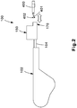
FIG. 2 is a side view of the system fromFIG. 1 where the fiber optic inspection module and the cleaning device are in a connected state, according to an exemplary embodiment of the present disclosure; -
FIG. 3 is a system diagram for the fiber optic inspection module, according to an exemplary embodiment of the present disclosure; -
FIG. 4 is the system diagram for the fiber optic inspection module fromFIG. 3 further including an external adapter, according to an exemplary embodiment of the present disclosure; -
FIG. 5A shows the fiber optic inspection module inFIG. 3 interacting with a cleaning tool in a first mode, according to an exemplary embodiment of the present disclosure; -
FIG. 5B shows the fiber optic inspection module inFIG. 3 interacting with the cleaning tool in a second mode, according to an exemplary embodiment of the present disclosure; -
FIG. 5C shows the fiber optic inspection module inFIG. 3 interacting with the cleaning tool in a third mode, according to an exemplary embodiment of the present disclosure; -
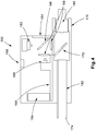
FIG. 6A shows a system diagram for a fiber optic inspection module according to an alternative embodiment, where the fiber optic inspection module is shown interacting with a cleaning tool according to the first mode; -
FIG. 6B shows the fiber optic inspection module ofFIG. 6A interacting with the cleaning tool according to the second mode; -
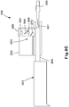
FIG. 6C shows the fiber optic inspection module ofFIG. 6A interacting with the cleaning tool according to the third mode; -
FIG. 7 is an enlarged view of the imaging components included in a submodule of components from the fiber optic inspection module shown inFIG. 6A . - The present disclosure relates to the field of optical network interconnection and optical assemblies and, more specifically, to apparatuses and methods to protect and maintain the cleanliness of optical fiber connector end-faces while optimizing network installation.
- Fiber optic connector end-faces must be clean prior to installation. Due to any number of factors, such as lack of training or experience of installers, faulty inspection procedures, and/or simply the pressure to meet schedule deadlines, connector end-faces may still be contaminated during installation. This has made connector contamination a cause of link failures, deployment delays, and excess cost.
- The need to meet tight schedules has only exacerbated the issues. Using separate tools for inspection and cleaning costs additional time and resources during an installation. A device that can do both, cleaning and inspecting without disconnecting or realigning the connector under test and where the operation can be repeated until the required degree of cleanliness can be achieved is unavailable in the market. There is a need for such a device, which can enable a more reliable installation of optical interconnects in data centers while reducing time and cost savings.
- These and other objects, features, and advantages of the present disclosure will become apparent to those having ordinary skill in the art upon reading this disclosure.
- Reference will now be made to the accompanying drawings. Wherever possible, the same reference numbers are used in the drawings and the following description to refer to the same or similar parts. It is to be expressly understood, however, that the drawings are for illustration and description purposes only. While several examples are described in this document, modifications, adaptations, and other implementations are possible. Accordingly, the following detailed description does not limit the disclosed examples. Instead, the proper scope of the disclosed examples may be defined by the appended claims.
-
FIGs. 1 and2 show a side view of a system diagram providing an overview of an exemplary inspection andcleaning system 100. The inspection andcleaning system 100 includes a fiberoptic inspection module 150 and acleaning device 102, where thecleaning device 102 includes aprobe 104. Thecleaning device 102 is used to clean a connector 400 (theconnector 400 could be a fiber optical connector or adapter), and the fiberoptic inspection module 150 is used to inspect theconnector 400. The fiberoptic inspection module 150 is a portable form factor visual inspection module configured to be attachable to standard fiber optic cleaners, such as thecleaning device 102. Thecleaning device 102 may be a fabric or tape-based cleaning device. As the cleaning feature (e.g., fabric or tape) moves using pay-off and/or take-up reels during a cleaning process, it will wipe and clean an end-face 401 of theconnector 400. Although the described embodiments may generally identify theconnector 400 as the component being inspected and/or cleaned by the inspection andcleaning system 100, other specific components such as theadapter components 402 and/or the connector end-face may be inspected and/or cleaned by the inspection andcleaning system 100. -
FIG. 1 shows the fiberoptic inspection module 150 and thecleaning device 102 of the inspection andcleaning system 100 spaced apart prior to the two components being assembled (i.e., connected) together.FIG. 2 shows the fiberoptic inspection module 150 and thecleaning device 102 assembled together in an assembled state ready for operation. Theprobe 104 is connected to the fiberoptic inspection module 150 in this assembled state. After thecleaning device 102 and the fiberoptic inspection module 150 are attached, they may operate as a single integrated tool that provides both cleaning and inspection functionalities without the need to disconnect theconnector 400. Once the fiberoptic inspection module 150 and thecleaning device 102 are connected, theconnector 400 is moved towards (and eventually into) aconnector adapter 170 portion of the fiberoptic inspection module 150 to be inspected and cleaned as desired. -
FIG. 3 is an internal side view of the components comprising the fiberoptic inspection module 150, andFIG. 4 is an internal side view of the components comprising the fiberoptic inspection module 150 further including anexternal adapter 180. The components shown inFIG. 3 are provided for exemplary purposes, as the fiber optic inspection module may include additional, or fewer, components according to other embodiments, while certain other components may not be expressly illustrated. - The fiber
optic inspection module 150 includes alight source 162, alens set 168 comprising at least two lenses, aconnector adapter 170, afirst mirror 172, acleaner adapter 152, abattery 154, acomputing system 156, animaging system 160, and anindicator 158. According to some alternative embodiments, the fiberoptic inspection module 150 may further include asecond mirror 166, anadapter sleeve 174, alight absorber 164, and anexternal adapter 180, as shown inFIG. 4 . - The
light source 162 emits light that is used to illuminate (at a desired wavelength of interest - e.g., blue LED or laser) the end-face 401 of theconnector 400 when theconnector 400 is inserted into the connector adapter 170 (or theexternal adapter 180 when it is included in the fiber optic inspection module 150). The light emitted from thelight source 162 is partially transmitted by thesecond mirror 166 towards the lenses included in thelens set 168. Thefirst mirror 172 receives this light and reflects it towards the end-face 401 of theconnector 400 under test. Using this system, at least one lens in the lens set 168 is used to focus light from thelight source 162 to the end-face 401 of theconnector 400. The lenses in the lens set 168 are also used to transfer the light reflected from the end-face 401 of the connector back to theimaging system 160. The lenses in the lens set 168 are positioned and configured within the fiberoptic inspection module 150 to provide an optical magnification feature to detect debris and/or other contamination on the end-face 401 of the connector 400 (e.g., this is equivalent magnification to an optical microscope, 100X, 200X, or 400X). - The
imaging system 160 is a camera or other device comprising an image sensor (or more than one camera or image sensor). The image sensor included in theimaging system 160 may be a CMOS sensor or a CCD sensor. Theimaging system 160 captures an image of the connector end-face 401 at desired wavelengths of interest (e.g., blue spectral region, UV spectral region, or near infra-red spectral (NIR) region). - The
computing system 156 includes hardware, software, and/or circuitry to control and operate the fiberoptic inspection module 150 according to the features described herein. Thecomputing system 156 may include wireless network interface(s) to enable the fiberoptic inspection module 150 to communicate with an external computing device using known wireless communication protocols such as Bluetooth, WiFi, and/or Near Field Communication (NFC). Thecomputing system 156 may include machine readable memory configured to store machine readable instructions, and one or more processors and/or controllers that, when executing the machine readable instructions stored on the memory, cause the fiberoptic inspection module 150 to control theimaging system 160, control thelight source 162, perform image analysis on images captured of the end-face 401, and/or perform wireless communication with a mobile device (as described in more detail below), as well as other functionalities of the device. - According to some embodiments, the
computing system 156 on the fiberoptic inspection module 150 may analyze the captured images of the end-face 401 received from theimaging system 160 directly to determine whether a contamination exists on the end-face 401. According to other alternative embodiments, thecomputing system 156 may include the wireless network interface(s) and communication devices for communicating with an external computing device using wireless signals to transmit the captured images of the end-face 401 so that the mobile device performs the image analysis and transmits the results of whether a contamination was identified back to the fiberoptic inspection module 150. The external computing device may be a mobile computing device (e.g., smartphone, tablet, or laptop) being handled by the on-site installer, or an off-site computing station (e.g., cloud computing server computer or work station) having greater computing resources to apply image analysis on the captured of the end-face 401 and identify a contamination with greater accuracy. - In addition to the image analysis to determine whether a contamination exists on the end-
face 401 of theconnector 400, a degree of contamination identified from the image analysis may be compared with the limits defined by industry standards (e.g., IEC 61300-3-35 Basic Test and Measurement Procedures Standard for Fiber Optic Interconnecting device and Passive Components) according to some embodiments. Then based on this analysis, the fiberoptic inspection module 150 may be configured to provide a pass/fail indication signal based on the analysis of the captured image. For example, when the level of contamination identified from the captured images is determined to be below the compared industry standard, a fail indication signal is presented. On the other hand, when the level of contamination identified from the captured images is determined to meet or exceed the compared industry standard, a pass indication signal is presented. - The
indicator 158 may be an audible indicator (e.g., speaker for transmitting an alarm sound), or a visual indicator (e.g., LED light or LCD display screen with or without touch screen capabilities). The results of the image evaluation may be presented via theindicator 158. A passing signal may be shown as a green light, check mark, predetermined message, or other indication perceivable via the senses. If theconnector 400 passes, the operator may move on and test the next connector or adapter. - A fail condition may trigger additional signals or algorithms to clean the
connector 400 and/or may illuminate theindicator 158. If not done automatically, the operator will clean the end-face of the connector. To do this, the operator pushes theprobe 104 into thecleaner adapter 152 of the fiberoptic inspection module 150. The pressure of theprobe 104 triggers the movement of the cleaning tape in thecleaning device 102. The movement of the tape over the connector end-face cleans the connector (e.g., as shown inFIG. 5c ). This procedure may be repeated until the connector passes the required/desired degree of cleanliness, thecleaning device 102 runs out of tape, or it is determined that theconnector 400 is unable to be properly cleaned. A report with test data (time, operator, etc.) and data related to theconnector 400's status and captured images may be stored on a memory in theinspection module 150 or transmitted for storage on a memory of an external device. In addition or alternatively, this data may be transmitted for storage in the cloud. - The
light absorber 164 may be included in the fiberoptic inspection module 150 to eliminate spurious light that can degrade the signal to noise ratio of the fiberoptic inspection module 150. In an alternate embodiment, thelight absorber 164 may be replaced with a lens to provide external light that can facilitate the use of the fiberoptic inspection module 150 in dark areas inside a data center or LAN (e.g., inside cabinets). Thebattery 154 is included to power components of the fiberoptic inspection module 150 such as thecomputing system 156, thelight source 162, theimaging system 160, and/or theindicator 158. - For the fiber
optic inspection module 150 to operate with different embodiments of thecleaning device 102, the fiberoptic inspection module 150 may be adapted to utilize different versions of thecleaner adapter 152 and theadapter sleeve 174 to accurately mate with thecleaning device 102. Therefore, the dimensions of thecleaner adapter 152 may depend on the type ofconnector 400 thecleaning device 102 is designed to clean (e.g., FOCIS-5 for the MTP/MPO fiber optic connector intermate ability standard). Theadapter sleeve 174 may be an optional removable component that is placed in thecleaner adapter 152. Theadapter sleeve 174 is removable and may be designed to be compatible to operate with a wider plurality of cleaning tools of different internal geometries. - Similarly, the shape and dimension of
connector adapter 170 may be adjusted, adjustable, and/or exchangeable for different types of connectors and adapters. For mating connectors, theconnector adapter 170 has a concave shape with the specific dimensions required to accept a connector. For mating an adapter already attached to a connector,connector adapter 170 will have a protruding shape to go inside the adapter. Additionally, theexternal adapter 180 may be attached to the fiberoptic inspection module 150 to inspect optical receptacles or adapters used in cassettes. An additional lens may be added to theexternal adapter 180 to compensate for an increase in working distance between the end-face 401 of theconnector 400 and theimaging system 160. -
FIGs. 5A to 5C show side views of the inspection andcleaning system 100 operating in three distinct modes. Before beginning the operational modes, an operator may verify that the fiberoptic inspection module 150 is compatible with thecleaning device 102. Once verified, the operator may connect thecleaning device 102 to the fiberoptic inspection module 150. - In
FIG. 5A , the inspection andcleaning system 100 is configured in an inspection mode where thecleaning device 102 and fiberoptic inspection module 150 are attached together. When the fiberoptic inspection module 150 is ready to operate, a visual (or audible) indication may be provided by the indicator 158 (e.g., such as a yellow light) showing thesystem 100 is ready to inspect and clean. - The
connector 400 is then inserted into the fiberoptic inspection module 150, as seen inFIG. 5A , for evaluation. At this point when theconnector 400 has been inserted into the fiberoptic inspection module 150, the end-face 401 of theconnector 400 is imaged and evaluated during the inspection mode. Thefirst mirror 172 is tilted approximately 45 degrees, enabling the transmission of light from thelight source 162 to the end-face 401 of theconnector 400. The visual components of the fiberoptic inspection module 150 detect reflected light from the end-face 401 of theconnector 400 and may autofocus and capture the image of the end-face 401. The fiberoptic inspection module 150 evaluates the degree of focus, detects the connector type, and may ask the user to readjust or reinstall theconnector 400 when additional images are needed to detect contamination. In an alternate embodiment, the user may activate an external control (e.g., button, trigger, mechanical or electrical remote) using a mobile device to begin inspection and/or cleaning. - The fiber
optic inspection module 150 may use the on-board computing system 156 or an external processor (remote device) to evaluate the captured image and report the degree of cleanliness by providing a pass/fail signal. If theconnector 400 passes, theindicator 158 presents a passing signal (e.g., a green LED), indicating that the operator may remove theconnector 400. If theconnector 400 fails the test, theindicator 158 presents a fail signal (e.g., a red LED). If theconnector 400 fails the test, the operator may clean theconnector 400 again. To do so, as shown inFIG. 5b , the user presses thecleaning device 102 towards the fiberoptic inspection module 150, causing the mirror to move. - The
first mirror 172 is movable in the form of tilting, translation, or a combination of tilting and translation during a transition mode, as shown by the exemplary tilting/pivoting of thefirst mirror 172 inFIG. 5B . During the imaging process, thefirst mirror 172 is situated at a tilt of approximately 45 degrees relative to the optical axis of the system. To clean theconnector 400, the operator presses thecleaning device 102 against the fiberoptic inspection module 150. The pressure moves theprobe 104, which holds the cleaning head of thecleaning device 102, into the fiberoptic inspection module 150 guided by thecleaner adapter 152 and/or theadapter sleeve 174. The movingprobe 104 then triggers a mechanism to displace thefirst mirror 172. - Finally in a cleaning mode, the
first mirror 172 or a holder of thefirst mirror 172 is pushed by theprobe 104 and rotated up to be approximately zero degrees horizontal as shown inFIG. 5C , thus enabling theprobe 104 to reach the end-face 401 of theconnector 400. As seen inFIG. 5B andFIG. 5C , this mechanism of the fiberoptic inspection module 150 enables theprobe 104 to push against the back of thefirst mirror 172, causing thefirst mirror 172 to pivot (i.e., rotate) about a fixed point. The rotation of thefirst mirror 172 about the fixed point may be accomplished by thefirst mirror 172 being attached to a type of hinge, door, or other rotatable device. The fixed point is located at the top of thefirst mirror 172. As shown by the transition fromFIGs. 5A to 5C , the top of thefirst mirror 172 stays in the same spot while the bottom portion of thefirst mirror 172 rotates upward as theprobe 104 abuts against thefirst mirror 172 and travels further into the fiberoptic inspection module 150. As shown inFIG. 5C , in the cleaning mode thefirst mirror 172 is completely tilted or moved out of the path of theprobe 104 so that theprobe 104 may reach the end-face 401 of theconnector 400. This movement opens a path for theprobe 104 to clean the end-face 401 of theconnector 400. - In an example, the
probe 104 may contact a non-reflective side (back side) of thefirst mirror 172. Alternatively, a mechanism by movement of theprobe 104 with respect to the fiber optic inspection module 150 (or theadapter sleeve 174 or the cleaner adapter 152) can move thefirst mirror 172 without directly contacting the back side of thefirst mirror 172. - In an alternate embodiment, the mirror hinge/door pivot may be activated without physical contact on the back of the
first mirror 172. For example, the insertion of theprobe 104 further into the fiberoptic inspection module 150 may cause a door or trigger to be moved out of the path of theprobe 104 before thefirst mirror 172 is contacted by theprobe 104. The door/trigger may be connected to thefirst mirror 172 through a belt coupler that will cause thefirst mirror 172 to pivot due to theprobe 104's contact with the door/trigger. Similarly, thefirst mirror 172 may be moved using gears, a bar attaching between a door/trigger and thefirst mirror 172, other mechanical configurations or electronics/a motor. In a further alternate embodiment, theadapter sleeve 174 may trigger the mechanism that displaces thefirst mirror 172. -
FIGs. 6A to 6C show an exemplary cleaning andinspection system 200 operating in various operational modes according to an alternative embodiment that includes an alternate mechanism and method of moving thefirst mirror 272. The cleaning andinspection system 200 operates to inspect and clean the end-face 401 of theconnector 400. The cleaning andinspection system 200 includes acleaning device 202 that includes aprobe 204. The cleaning andinspection system 200 further includes aninspection module 250. Theinspection module 250 includescomputing system 256, acamera 260, alight source 262, afirst mirror 272, asecond mirror 266, and alens 268. In this example, thefirst mirror 272, thesecond mirror 266, thelight source 262 and thelens 268 form asubmodule 290, as indicated by the portion A illustrated inFIG. 6A and also provided in the enlarged view ofFIG. 7 . According to the cleaning andinspection system 200, when theprobe 204 is advanced into theinspection module 250, theprobe 204 actuates a trigger or intersects with thesubmodule 290 which causes thesubmodule 290 to be shifted upward, out of the path of theprobe 204. This provides a path for theprobe 204 to clean the end-face 401 of theconnector 400. - In an embodiment, the
submodule 290 may be shifted upward in a mechanical fashion. For example, theprobe 204 or a portion of theinspection module 250 may be slidable and have an angled surface. Thesubmodule 290 may also have an angled surface. When the two angled surfaces interact, the angled surface on theprobe 204 and/or the angled surface of theinspection module 250 may push thesubmodule 290 in an upward direction. Alternatively, thesubmodule 290 may move upwards using other mechanical means, gears, motors, or electronics, which may require the use of a trigger (such as a button, door, etc.). In a further alternate embodiment, the movement of thesubmodule 290 is caused by a remote or mobile device triggering the movement of thesubmodule 290. - The described inspection module provides an apparatus and method for fast inspection and cleaning of optical connectors and adapters. The apparatus can inspect and clean optical interconnects or patch cord connector end-faces without the need of manually removing and installing the connector from an inspection tool to a separate cleaner device. Alternatively, the apparatus can inspect and clean patch panels or cassette adapters without removing the adapter from the inspection tool to another cleaning tool. The disclosed device may be applied to several types of single, duplex or parallel optical connectors such as LC, SC, CS, SN, MTP/MPO. It may also be used with their connector adapters.
- Note that while the present disclosure includes several embodiments, these embodiments are non-limiting, and there are alterations, permutations, and equivalents, which fall within the scope of this disclosure. Additionally, the described embodiments should not be interpreted as mutually exclusive, and, should instead be understood as potentially combinable if such combinations are permissive. It should also be noted that there may be alternative ways of implementing the embodiments of the present disclosure. It is therefore intended that claims that may follow be interpreted as including all such alterations, permutations, and equivalents as fall within the true spirit and scope of the present disclosure.
Claims (15)
- A fiber optic inspection module, comprising:a camera configured to capture an image of an end-face;a light source configured to illuminate the end-face; anda first mirror including a fixed point about which the first mirror is configured to pivot, wherein the first mirror is configured to reflect light from the light source to the end-face.
- The fiber optic inspection module of claim 1, further comprising a lens set including at least one lens.
- The fiber optic inspection module of claim 2, wherein the lens set is included in the transfer of the image of the end-face to the camera, or/and optionally wherein the fiber option inspection module further comprising a second mirror, wherein the light from the light source is reflected by the second mirror towards the lens set.
- The fiber optic inspection module of any preceding claim, further comprising:
a first aperture, wherein the first aperture is sized to receive a probe end of a cleaning device. - The fiber optic inspection module of claim 4, wherein the first aperture holds an adaptor sleeve, or/and optionally wherein the fiber optic inspection module further comprises a second aperture, wherein the second aperture is sized to receive a fiber optic connector.
- The fiber optic inspection module of any preceding claim, further comprising:a processor; anda memory storing machine-readable instructions that, when executed by the processor, causes the processor to control the camera, and optionally wherein the memory further storing machine-readable instructions that, when executed by the processor, causes the processor to perform image analysis on the image of the end-face.
- The fiber optic inspection module of any preceding claim, further comprising:
a wireless communication device configured to communicate with at least one external device. - The fiber optic inspection module of any preceding claim, further comprising:
a battery configured to power the camera. - The fiber optic inspection module of any preceding claim, further comprising:
a visual indicator configured to provide notification of a condition of the end-face based on an analysis of the image of the end-face. - The fiber optic inspection module of claim 12, wherein the condition is at least one of a pass condition or a fail condition, or/and optionally wherein the visual indicator is one of an LED screen and an LCD screen.
- The fiber optic inspection module of any preceding claim, further comprising:
an absorber configured to eliminate spurious light. - The fiber optic inspection module of any preceding claim, wherein the light source is one of an LED or a laser.
- The fiber optic inspection module of any preceding claim, wherein the pivot of the first mirror about the fixed point is perpendicular to a movement of a probe end of a cleaning device inserted into the fiber optic inspection module.
- The fiber optic inspection module of any preceding claim, wherein the first mirror is tilted 45 degrees relative to an optical axis of the fiber optic inspection module.
- A fiber optic inspection module, comprising:a camera configured to capture an image of an end-face;a light source configured to illuminate the end-face;a first mirror configured to reflect light from the light source to the end-face; andwherein the camera, the light source, and the first mirror moves in an upward direction and out of a pathway for a cleaning device inserted into the fiber optic inspection module.
Applications Claiming Priority (2)
| Application Number | Priority Date | Filing Date | Title |
|---|---|---|---|
| US201962907093P | 2019-09-27 | 2019-09-27 | |
| US17/026,556 US11808658B2 (en) | 2019-09-27 | 2020-09-21 | Visual inspector attachment for fiber connector cleaners |
Publications (2)
| Publication Number | Publication Date |
|---|---|
| EP3800460A1 true EP3800460A1 (en) | 2021-04-07 |
| EP3800460B1 EP3800460B1 (en) | 2022-08-03 |
Family
ID=72615734
Family Applications (1)
| Application Number | Title | Priority Date | Filing Date |
|---|---|---|---|
| EP20197708.9A Active EP3800460B1 (en) | 2019-09-27 | 2020-09-23 | Visual inspector attachment for fiber connector cleaners |
Country Status (2)
| Country | Link |
|---|---|
| US (2) | US11808658B2 (en) |
| EP (1) | EP3800460B1 (en) |
Cited By (1)
| Publication number | Priority date | Publication date | Assignee | Title |
|---|---|---|---|---|
| WO2023122218A1 (en) * | 2021-12-22 | 2023-06-29 | Bard Access Systems, Inc. | Medical ferrule cleaning device |
Families Citing this family (3)
| Publication number | Priority date | Publication date | Assignee | Title |
|---|---|---|---|---|
| US11644626B2 (en) * | 2019-09-30 | 2023-05-09 | Panduit Corp. | Fiber optic inspection tool with integrated cleaning mechanism |
| US11899248B2 (en) * | 2020-03-06 | 2024-02-13 | Intuitive Surgical Operations, Inc. | Systems and methods for optical fiber cleaning and interface particle reduction |
| CN120314323B (en) * | 2025-06-18 | 2025-08-29 | 北京瑞祺皓迪技术股份有限公司 | Method, device, equipment and medium for detecting and cleaning impurities on end face of optical fiber |
Citations (4)
| Publication number | Priority date | Publication date | Assignee | Title |
|---|---|---|---|---|
| US20040125366A1 (en) * | 2002-12-26 | 2004-07-01 | Sepehr Kiani | Systems and methods for inspecting an optical interface |
| US20130229650A1 (en) * | 2012-03-05 | 2013-09-05 | Fiberqa, Llc | System and method of an integrated fiber optic inspection and cleaning apparatus |
| US20140268114A1 (en) * | 2013-03-15 | 2014-09-18 | Lightel Technologies Inc. | Apparatus for simultaneously inspecting and cleaning fiber connector |
| WO2018009802A1 (en) * | 2016-07-08 | 2018-01-11 | Commscope Technologies Llc | Fiber optic ferrule inspection tool with contamination detection and cleaning device |
Family Cites Families (40)
| Publication number | Priority date | Publication date | Assignee | Title |
|---|---|---|---|---|
| JPS5777935A (en) * | 1980-11-04 | 1982-05-15 | Agency Of Ind Science & Technol | Safety device for photoconductive path |
| IT1199897B (en) * | 1985-07-22 | 1989-01-05 | Cselt Centro Studi Lab Telecom | METHOD AND DEVICE FOR THE MEASUREMENT OF COUPLING LOSSES BETWEEN SINGLE-MODE OPTICAL FIBERS |
| US5179419A (en) | 1991-11-22 | 1993-01-12 | At&T Bell Laboratories | Methods of detecting, classifying and quantifying defects in optical fiber end faces |
| JP3191901B2 (en) | 1994-09-29 | 2001-07-23 | 本多通信工業株式会社 | Optical connector cleaning tool |
| US5809162A (en) | 1995-12-22 | 1998-09-15 | Lucent Technologies Inc. | Surface analysis system and method |
| US5898494A (en) | 1995-04-27 | 1999-04-27 | Lucent Technologies Inc. | Automatic inspection system and method for contactlessly measuring the disparity between two surfaces |
| US5729622A (en) | 1995-08-02 | 1998-03-17 | Lucent Technologies Inc. | Automatic inspection system for contactlessly measuring an offset of a central feature of an object |
| US5836031A (en) | 1996-06-07 | 1998-11-17 | Minnesota Mining And Manufacturing Company | Fiber optic cable cleaner |
| JP2845791B2 (en) | 1996-01-22 | 1999-01-13 | 宮城日本電気株式会社 | Optical connector end face cleaner |
| WO1998014810A2 (en) | 1996-09-30 | 1998-04-09 | Sang Van Nguyen | Automatic fiber optic connectorization and inspection system (afocis) |
| US5995212A (en) | 1998-07-28 | 1999-11-30 | Ciena Corporation | System and method for inspecting an optical fiber including an epoxy area surrounding the optical fiber |
| US6209162B1 (en) | 1999-03-26 | 2001-04-03 | Molex Incorporated | System for cleaning fiber optic connectors |
| US6209163B1 (en) | 1999-03-26 | 2001-04-03 | Molex Incorporated | Cleaner for fiber optic connectors |
| US6415471B1 (en) | 1999-06-30 | 2002-07-09 | Corning Cable Systems Llc | Device for cleaning mechanism for fiber optic connectors |
| WO2002057825A1 (en) | 2001-01-17 | 2002-07-25 | Toray Industries, Inc. | Optical connector cleaning device |
| US6831738B2 (en) | 2001-06-26 | 2004-12-14 | Adc Telecommunications, Inc. | Method and apparatus for inspecting end surfaces on optical connectors |
| US6854152B2 (en) | 2001-11-29 | 2005-02-15 | 3M Innovative Properties Company | Article and process for cleaning optical surfaces |
| US6989895B2 (en) | 2002-03-18 | 2006-01-24 | Mike Buzzetti | Automated fiber optic inspection system |
| US6760534B1 (en) | 2002-06-10 | 2004-07-06 | Randall L. Son | Fiber scope and cleaning tool |
| JP4015032B2 (en) | 2002-12-02 | 2007-11-28 | 株式会社フジクラ | Optical connector cleaning unit and optical connector cleaning tool |
| US6758605B1 (en) * | 2003-02-21 | 2004-07-06 | Telops Inc. | Cleaning device and method for optical connectors |
| US7023557B2 (en) * | 2003-08-05 | 2006-04-04 | Agilent Technologies, Inc. | Parallel interferometric measurements using an expanded local oscillator signal |
| US7837801B2 (en) | 2006-06-06 | 2010-11-23 | Ksaria Corporation | Apparatus and method for cleaning an optical fiber |
| US7356236B1 (en) * | 2006-12-14 | 2008-04-08 | Lightel Technologies Inc. | Field-use apparatus for inspecting and cleaning fiber optic connectors |
| JP5579063B2 (en) * | 2007-08-24 | 2014-08-27 | カール・ツァイス・エスエムティー・ゲーエムベーハー | Controllable optical element, method of operating optical element with thermal actuator, and projection exposure apparatus for semiconductor lithography |
| US8235322B1 (en) | 2008-02-24 | 2012-08-07 | Teliswitch Solutions Ltd. | Handling excess optical fiber |
| US9217688B2 (en) | 2009-10-08 | 2015-12-22 | Piotr Anatolij Levin | Fiber optic end face inspection probe and system |
| JP5525628B2 (en) | 2012-01-19 | 2014-06-18 | エヌ・ティ・ティ・アドバンステクノロジ株式会社 | Optical connector cleaning tool |
| EP2746829B1 (en) | 2012-08-09 | 2019-10-02 | Fujikura Ltd. | Optical connector cleaning tool and optical connector cleaning method |
| CN105122108B (en) | 2013-03-13 | 2017-03-22 | Ntt尖端技术株式会社 | Cleaning tool for optical connector |
| TWI457629B (en) | 2013-03-18 | 2014-10-21 | Hobbes & Co Ltd | Fiber Connector Cleaning Belt Set |
| CN104056793B (en) | 2013-03-18 | 2016-05-18 | 株式会社精工技研 | Joints of optical fibre cleaning cleaner |
| US9417444B2 (en) | 2013-05-01 | 2016-08-16 | Lightel Technologies, Inc. | User-friendly wireless fiber optic endface inspector |
| WO2015073850A1 (en) | 2013-11-15 | 2015-05-21 | Afl Telecommunications Llc | Wireless inspection solution |
| WO2015093470A1 (en) | 2013-12-16 | 2015-06-25 | 日本電信電話株式会社 | End-surface observation device |
| JP5947325B2 (en) | 2014-03-10 | 2016-07-06 | エヌ・ティ・ティ・アドバンステクノロジ株式会社 | Optical connector cleaning tool and optical connector surface observation system |
| WO2016069684A1 (en) | 2014-10-30 | 2016-05-06 | Corning Incorporated | Optical systems including lens assemblies and methods of imaging fields of view using such optical systems |
| US10254487B2 (en) | 2015-03-30 | 2019-04-09 | Lightel Technologies, Inc. | All-in-one fiber optic connector inspection probe with embedded web server and wireless transmitter |
| US10090914B2 (en) * | 2015-10-13 | 2018-10-02 | Fluke Corporation | Test probes for smart inspection |
| CN105996995B (en) * | 2016-05-03 | 2018-09-07 | 华南师范大学 | A kind of tympanitis diagnostic system and instrument based on spectral technique |
-
2020
- 2020-09-21 US US17/026,556 patent/US11808658B2/en active Active
- 2020-09-23 EP EP20197708.9A patent/EP3800460B1/en active Active
-
2023
- 2023-10-02 US US18/375,601 patent/US12007297B2/en active Active
Patent Citations (4)
| Publication number | Priority date | Publication date | Assignee | Title |
|---|---|---|---|---|
| US20040125366A1 (en) * | 2002-12-26 | 2004-07-01 | Sepehr Kiani | Systems and methods for inspecting an optical interface |
| US20130229650A1 (en) * | 2012-03-05 | 2013-09-05 | Fiberqa, Llc | System and method of an integrated fiber optic inspection and cleaning apparatus |
| US20140268114A1 (en) * | 2013-03-15 | 2014-09-18 | Lightel Technologies Inc. | Apparatus for simultaneously inspecting and cleaning fiber connector |
| WO2018009802A1 (en) * | 2016-07-08 | 2018-01-11 | Commscope Technologies Llc | Fiber optic ferrule inspection tool with contamination detection and cleaning device |
Cited By (2)
| Publication number | Priority date | Publication date | Assignee | Title |
|---|---|---|---|---|
| WO2023122218A1 (en) * | 2021-12-22 | 2023-06-29 | Bard Access Systems, Inc. | Medical ferrule cleaning device |
| CN116475105A (en) * | 2021-12-22 | 2023-07-25 | 巴德阿克塞斯系统股份有限公司 | Optical connector cleaning device and related method |
Also Published As
| Publication number | Publication date |
|---|---|
| US11808658B2 (en) | 2023-11-07 |
| US20210096039A1 (en) | 2021-04-01 |
| US20240035925A1 (en) | 2024-02-01 |
| US12007297B2 (en) | 2024-06-11 |
| EP3800460B1 (en) | 2022-08-03 |
Similar Documents
| Publication | Publication Date | Title |
|---|---|---|
| US12007297B2 (en) | Visual inspector attachment for fiber connector cleaners | |
| US11644626B2 (en) | Fiber optic inspection tool with integrated cleaning mechanism | |
| EP3495797B1 (en) | Method and system for multi-fiber cable testing | |
| JP6782100B2 (en) | Authentication system for physical parameters of communication links and its method | |
| US7042562B2 (en) | Systems and methods for inspecting an optical interface | |
| US10175142B2 (en) | Multiple-fiber connector inspection | |
| US9417444B2 (en) | User-friendly wireless fiber optic endface inspector | |
| WO2013097041A1 (en) | Portable digital holographic probe for the inspection of optical fiber connectors, and inspection system and method for the same | |
| EP3156779A1 (en) | Three-dimensional inspection of optical communication links | |
| WO2016033139A1 (en) | Non-contact method of measuring insertion loss in optical fiber connectors using active alignment | |
| US20180283986A1 (en) | Dual purpose optical test instrument | |
| US20260050128A1 (en) | Mpo adapter for apc connector inspection | |
| US20260016368A1 (en) | Apparatus and System for Visual Inspection of Fiber Ends and Image Analysis Tool for Detecting Contamination | |
| CN108124096B (en) | End face inspection apparatus and focused image data acquisition method thereof | |
| US20150116699A1 (en) | Removable device for inspecting polish of an optical fiber endface using a portable camera, and related components, systems, and methods | |
| US20150116700A1 (en) | Device for inspecting a cleave of an optical fiber endface, and related components, systems and methods | |
| EP3968068B1 (en) | Optical fiber endface inspection microscope having adapter tip detection and autoconfiguration | |
| US20230185030A1 (en) | Ferrule profile imaging and measurement | |
| KR101572858B1 (en) | WiFi fiber optic inspector | |
| EP3156780B1 (en) | Test probes for smart inspection | |
| US20220268664A1 (en) | Polarity test system and method used for multi-fiber optical cables | |
| KR101951701B1 (en) | Fiber guide measuring apparatus | |
| Huang et al. | An Apparatus for Fast Inspecting and Cleaning Connector | |
| EP4671839A1 (en) | AUTOMATED INSPECTION AND CLEANING OF FIBER OPTIC COMPONENTS | |
| JP2018087708A (en) | End face inspection apparatus and focused image data acquisition method thereof |
Legal Events
| Date | Code | Title | Description |
|---|---|---|---|
| PUAI | Public reference made under article 153(3) epc to a published international application that has entered the european phase |
Free format text: ORIGINAL CODE: 0009012 |
|
| STAA | Information on the status of an ep patent application or granted ep patent |
Free format text: STATUS: THE APPLICATION HAS BEEN PUBLISHED |
|
| AK | Designated contracting states |
Kind code of ref document: A1 Designated state(s): AL AT BE BG CH CY CZ DE DK EE ES FI FR GB GR HR HU IE IS IT LI LT LU LV MC MK MT NL NO PL PT RO RS SE SI SK SM TR |
|
| AX | Request for extension of the european patent |
Extension state: BA ME |
|
| STAA | Information on the status of an ep patent application or granted ep patent |
Free format text: STATUS: REQUEST FOR EXAMINATION WAS MADE |
|
| 17P | Request for examination filed |
Effective date: 20211007 |
|
| RBV | Designated contracting states (corrected) |
Designated state(s): AL AT BE BG CH CY CZ DE DK EE ES FI FR GB GR HR HU IE IS IT LI LT LU LV MC MK MT NL NO PL PT RO RS SE SI SK SM TR |
|
| GRAP | Despatch of communication of intention to grant a patent |
Free format text: ORIGINAL CODE: EPIDOSNIGR1 |
|
| STAA | Information on the status of an ep patent application or granted ep patent |
Free format text: STATUS: GRANT OF PATENT IS INTENDED |
|
| INTG | Intention to grant announced |
Effective date: 20220317 |
|
| GRAS | Grant fee paid |
Free format text: ORIGINAL CODE: EPIDOSNIGR3 |
|
| GRAA | (expected) grant |
Free format text: ORIGINAL CODE: 0009210 |
|
| STAA | Information on the status of an ep patent application or granted ep patent |
Free format text: STATUS: THE PATENT HAS BEEN GRANTED |
|
| AK | Designated contracting states |
Kind code of ref document: B1 Designated state(s): AL AT BE BG CH CY CZ DE DK EE ES FI FR GB GR HR HU IE IS IT LI LT LU LV MC MK MT NL NO PL PT RO RS SE SI SK SM TR |
|
| REG | Reference to a national code |
Ref country code: AT Ref legal event code: REF Ref document number: 1509107 Country of ref document: AT Kind code of ref document: T Effective date: 20220815 Ref country code: CH Ref legal event code: EP |
|
| REG | Reference to a national code |
Ref country code: DE Ref legal event code: R096 Ref document number: 602020004322 Country of ref document: DE |
|
| REG | Reference to a national code |
Ref country code: IE Ref legal event code: FG4D |
|
| REG | Reference to a national code |
Ref country code: LT Ref legal event code: MG9D |
|
| REG | Reference to a national code |
Ref country code: NL Ref legal event code: MP Effective date: 20220803 |
|
| PG25 | Lapsed in a contracting state [announced via postgrant information from national office to epo] |
Ref country code: SE Free format text: LAPSE BECAUSE OF FAILURE TO SUBMIT A TRANSLATION OF THE DESCRIPTION OR TO PAY THE FEE WITHIN THE PRESCRIBED TIME-LIMIT Effective date: 20220803 Ref country code: RS Free format text: LAPSE BECAUSE OF FAILURE TO SUBMIT A TRANSLATION OF THE DESCRIPTION OR TO PAY THE FEE WITHIN THE PRESCRIBED TIME-LIMIT Effective date: 20220803 Ref country code: PT Free format text: LAPSE BECAUSE OF FAILURE TO SUBMIT A TRANSLATION OF THE DESCRIPTION OR TO PAY THE FEE WITHIN THE PRESCRIBED TIME-LIMIT Effective date: 20221205 Ref country code: NO Free format text: LAPSE BECAUSE OF FAILURE TO SUBMIT A TRANSLATION OF THE DESCRIPTION OR TO PAY THE FEE WITHIN THE PRESCRIBED TIME-LIMIT Effective date: 20221103 Ref country code: NL Free format text: LAPSE BECAUSE OF FAILURE TO SUBMIT A TRANSLATION OF THE DESCRIPTION OR TO PAY THE FEE WITHIN THE PRESCRIBED TIME-LIMIT Effective date: 20220803 Ref country code: LV Free format text: LAPSE BECAUSE OF FAILURE TO SUBMIT A TRANSLATION OF THE DESCRIPTION OR TO PAY THE FEE WITHIN THE PRESCRIBED TIME-LIMIT Effective date: 20220803 Ref country code: LT Free format text: LAPSE BECAUSE OF FAILURE TO SUBMIT A TRANSLATION OF THE DESCRIPTION OR TO PAY THE FEE WITHIN THE PRESCRIBED TIME-LIMIT Effective date: 20220803 Ref country code: FI Free format text: LAPSE BECAUSE OF FAILURE TO SUBMIT A TRANSLATION OF THE DESCRIPTION OR TO PAY THE FEE WITHIN THE PRESCRIBED TIME-LIMIT Effective date: 20220803 Ref country code: ES Free format text: LAPSE BECAUSE OF FAILURE TO SUBMIT A TRANSLATION OF THE DESCRIPTION OR TO PAY THE FEE WITHIN THE PRESCRIBED TIME-LIMIT Effective date: 20220803 |
|
| REG | Reference to a national code |
Ref country code: AT Ref legal event code: MK05 Ref document number: 1509107 Country of ref document: AT Kind code of ref document: T Effective date: 20220803 |
|
| PG25 | Lapsed in a contracting state [announced via postgrant information from national office to epo] |
Ref country code: PL Free format text: LAPSE BECAUSE OF FAILURE TO SUBMIT A TRANSLATION OF THE DESCRIPTION OR TO PAY THE FEE WITHIN THE PRESCRIBED TIME-LIMIT Effective date: 20220803 Ref country code: IS Free format text: LAPSE BECAUSE OF FAILURE TO SUBMIT A TRANSLATION OF THE DESCRIPTION OR TO PAY THE FEE WITHIN THE PRESCRIBED TIME-LIMIT Effective date: 20221203 Ref country code: HR Free format text: LAPSE BECAUSE OF FAILURE TO SUBMIT A TRANSLATION OF THE DESCRIPTION OR TO PAY THE FEE WITHIN THE PRESCRIBED TIME-LIMIT Effective date: 20220803 Ref country code: GR Free format text: LAPSE BECAUSE OF FAILURE TO SUBMIT A TRANSLATION OF THE DESCRIPTION OR TO PAY THE FEE WITHIN THE PRESCRIBED TIME-LIMIT Effective date: 20221104 |
|
| PG25 | Lapsed in a contracting state [announced via postgrant information from national office to epo] |
Ref country code: SM Free format text: LAPSE BECAUSE OF FAILURE TO SUBMIT A TRANSLATION OF THE DESCRIPTION OR TO PAY THE FEE WITHIN THE PRESCRIBED TIME-LIMIT Effective date: 20220803 Ref country code: RO Free format text: LAPSE BECAUSE OF FAILURE TO SUBMIT A TRANSLATION OF THE DESCRIPTION OR TO PAY THE FEE WITHIN THE PRESCRIBED TIME-LIMIT Effective date: 20220803 Ref country code: DK Free format text: LAPSE BECAUSE OF FAILURE TO SUBMIT A TRANSLATION OF THE DESCRIPTION OR TO PAY THE FEE WITHIN THE PRESCRIBED TIME-LIMIT Effective date: 20220803 Ref country code: CZ Free format text: LAPSE BECAUSE OF FAILURE TO SUBMIT A TRANSLATION OF THE DESCRIPTION OR TO PAY THE FEE WITHIN THE PRESCRIBED TIME-LIMIT Effective date: 20220803 Ref country code: AT Free format text: LAPSE BECAUSE OF FAILURE TO SUBMIT A TRANSLATION OF THE DESCRIPTION OR TO PAY THE FEE WITHIN THE PRESCRIBED TIME-LIMIT Effective date: 20220803 |
|
| REG | Reference to a national code |
Ref country code: DE Ref legal event code: R097 Ref document number: 602020004322 Country of ref document: DE |
|
| REG | Reference to a national code |
Ref country code: BE Ref legal event code: MM Effective date: 20220930 |
|
| PG25 | Lapsed in a contracting state [announced via postgrant information from national office to epo] |
Ref country code: SK Free format text: LAPSE BECAUSE OF FAILURE TO SUBMIT A TRANSLATION OF THE DESCRIPTION OR TO PAY THE FEE WITHIN THE PRESCRIBED TIME-LIMIT Effective date: 20220803 Ref country code: MC Free format text: LAPSE BECAUSE OF FAILURE TO SUBMIT A TRANSLATION OF THE DESCRIPTION OR TO PAY THE FEE WITHIN THE PRESCRIBED TIME-LIMIT Effective date: 20220803 Ref country code: EE Free format text: LAPSE BECAUSE OF FAILURE TO SUBMIT A TRANSLATION OF THE DESCRIPTION OR TO PAY THE FEE WITHIN THE PRESCRIBED TIME-LIMIT Effective date: 20220803 |
|
| PLBE | No opposition filed within time limit |
Free format text: ORIGINAL CODE: 0009261 |
|
| STAA | Information on the status of an ep patent application or granted ep patent |
Free format text: STATUS: NO OPPOSITION FILED WITHIN TIME LIMIT |
|
| PG25 | Lapsed in a contracting state [announced via postgrant information from national office to epo] |
Ref country code: LU Free format text: LAPSE BECAUSE OF NON-PAYMENT OF DUE FEES Effective date: 20220923 Ref country code: AL Free format text: LAPSE BECAUSE OF FAILURE TO SUBMIT A TRANSLATION OF THE DESCRIPTION OR TO PAY THE FEE WITHIN THE PRESCRIBED TIME-LIMIT Effective date: 20220803 |
|
| 26N | No opposition filed |
Effective date: 20230504 |
|
| PG25 | Lapsed in a contracting state [announced via postgrant information from national office to epo] |
Ref country code: IE Free format text: LAPSE BECAUSE OF NON-PAYMENT OF DUE FEES Effective date: 20220923 |
|
| PG25 | Lapsed in a contracting state [announced via postgrant information from national office to epo] |
Ref country code: SI Free format text: LAPSE BECAUSE OF FAILURE TO SUBMIT A TRANSLATION OF THE DESCRIPTION OR TO PAY THE FEE WITHIN THE PRESCRIBED TIME-LIMIT Effective date: 20220803 |
|
| PG25 | Lapsed in a contracting state [announced via postgrant information from national office to epo] |
Ref country code: BE Free format text: LAPSE BECAUSE OF NON-PAYMENT OF DUE FEES Effective date: 20220930 |
|
| PG25 | Lapsed in a contracting state [announced via postgrant information from national office to epo] |
Ref country code: CY Free format text: LAPSE BECAUSE OF FAILURE TO SUBMIT A TRANSLATION OF THE DESCRIPTION OR TO PAY THE FEE WITHIN THE PRESCRIBED TIME-LIMIT Effective date: 20220803 |
|
| REG | Reference to a national code |
Ref country code: CH Ref legal event code: PL |
|
| PG25 | Lapsed in a contracting state [announced via postgrant information from national office to epo] |
Ref country code: MK Free format text: LAPSE BECAUSE OF FAILURE TO SUBMIT A TRANSLATION OF THE DESCRIPTION OR TO PAY THE FEE WITHIN THE PRESCRIBED TIME-LIMIT Effective date: 20220803 Ref country code: IT Free format text: LAPSE BECAUSE OF FAILURE TO SUBMIT A TRANSLATION OF THE DESCRIPTION OR TO PAY THE FEE WITHIN THE PRESCRIBED TIME-LIMIT Effective date: 20220803 Ref country code: HU Free format text: LAPSE BECAUSE OF FAILURE TO SUBMIT A TRANSLATION OF THE DESCRIPTION OR TO PAY THE FEE WITHIN THE PRESCRIBED TIME-LIMIT; INVALID AB INITIO Effective date: 20200923 |
|
| PG25 | Lapsed in a contracting state [announced via postgrant information from national office to epo] |
Ref country code: TR Free format text: LAPSE BECAUSE OF FAILURE TO SUBMIT A TRANSLATION OF THE DESCRIPTION OR TO PAY THE FEE WITHIN THE PRESCRIBED TIME-LIMIT Effective date: 20220803 |
|
| PG25 | Lapsed in a contracting state [announced via postgrant information from national office to epo] |
Ref country code: CH Free format text: LAPSE BECAUSE OF NON-PAYMENT OF DUE FEES Effective date: 20230930 |
|
| PG25 | Lapsed in a contracting state [announced via postgrant information from national office to epo] |
Ref country code: CH Free format text: LAPSE BECAUSE OF NON-PAYMENT OF DUE FEES Effective date: 20230930 Ref country code: BG Free format text: LAPSE BECAUSE OF FAILURE TO SUBMIT A TRANSLATION OF THE DESCRIPTION OR TO PAY THE FEE WITHIN THE PRESCRIBED TIME-LIMIT Effective date: 20220803 |
|
| PG25 | Lapsed in a contracting state [announced via postgrant information from national office to epo] |
Ref country code: MT Free format text: LAPSE BECAUSE OF FAILURE TO SUBMIT A TRANSLATION OF THE DESCRIPTION OR TO PAY THE FEE WITHIN THE PRESCRIBED TIME-LIMIT Effective date: 20220803 |
|
| PGFP | Annual fee paid to national office [announced via postgrant information from national office to epo] |
Ref country code: DE Payment date: 20250929 Year of fee payment: 6 |
|
| PGFP | Annual fee paid to national office [announced via postgrant information from national office to epo] |
Ref country code: GB Payment date: 20250929 Year of fee payment: 6 |
|
| PGFP | Annual fee paid to national office [announced via postgrant information from national office to epo] |
Ref country code: FR Payment date: 20250925 Year of fee payment: 6 |