EP3800406A1 - Air knife systems - Google Patents
Air knife systems Download PDFInfo
- Publication number
- EP3800406A1 EP3800406A1 EP19215268.4A EP19215268A EP3800406A1 EP 3800406 A1 EP3800406 A1 EP 3800406A1 EP 19215268 A EP19215268 A EP 19215268A EP 3800406 A1 EP3800406 A1 EP 3800406A1
- Authority
- EP
- European Patent Office
- Prior art keywords
- manifold
- build area
- inlet manifold
- outlet manifold
- inlet
- Prior art date
- Legal status (The legal status is an assumption and is not a legal conclusion. Google has not performed a legal analysis and makes no representation as to the accuracy of the status listed.)
- Granted
Links
Images

Classifications
-
- F—MECHANICAL ENGINEERING; LIGHTING; HEATING; WEAPONS; BLASTING
- F24—HEATING; RANGES; VENTILATING
- F24F—AIR-CONDITIONING; AIR-HUMIDIFICATION; VENTILATION; USE OF AIR CURRENTS FOR SCREENING
- F24F9/00—Use of air currents for screening, e.g. air curtains
-
- B—PERFORMING OPERATIONS; TRANSPORTING
- B08—CLEANING
- B08B—CLEANING IN GENERAL; PREVENTION OF FOULING IN GENERAL
- B08B5/00—Cleaning by methods involving the use of air flow or gas flow
- B08B5/02—Cleaning by the force of jets, e.g. blowing-out cavities
-
- B—PERFORMING OPERATIONS; TRANSPORTING
- B29—WORKING OF PLASTICS; WORKING OF SUBSTANCES IN A PLASTIC STATE IN GENERAL
- B29C—SHAPING OR JOINING OF PLASTICS; SHAPING OF MATERIAL IN A PLASTIC STATE, NOT OTHERWISE PROVIDED FOR; AFTER-TREATMENT OF THE SHAPED PRODUCTS, e.g. REPAIRING
- B29C64/00—Additive manufacturing, i.e. manufacturing of three-dimensional [3D] objects by additive deposition, additive agglomeration or additive layering, e.g. by 3D printing, stereolithography or selective laser sintering
- B29C64/20—Apparatus for additive manufacturing; Details thereof or accessories therefor
-
- B—PERFORMING OPERATIONS; TRANSPORTING
- B29—WORKING OF PLASTICS; WORKING OF SUBSTANCES IN A PLASTIC STATE IN GENERAL
- B29C—SHAPING OR JOINING OF PLASTICS; SHAPING OF MATERIAL IN A PLASTIC STATE, NOT OTHERWISE PROVIDED FOR; AFTER-TREATMENT OF THE SHAPED PRODUCTS, e.g. REPAIRING
- B29C64/00—Additive manufacturing, i.e. manufacturing of three-dimensional [3D] objects by additive deposition, additive agglomeration or additive layering, e.g. by 3D printing, stereolithography or selective laser sintering
- B29C64/30—Auxiliary operations or equipment
- B29C64/364—Conditioning of environment
-
- B—PERFORMING OPERATIONS; TRANSPORTING
- B33—ADDITIVE MANUFACTURING TECHNOLOGY
- B33Y—ADDITIVE MANUFACTURING, i.e. MANUFACTURING OF THREE-DIMENSIONAL [3D] OBJECTS BY ADDITIVE DEPOSITION, ADDITIVE AGGLOMERATION OR ADDITIVE LAYERING, e.g. BY 3D PRINTING, STEREOLITHOGRAPHY OR SELECTIVE LASER SINTERING
- B33Y10/00—Processes of additive manufacturing
-
- B—PERFORMING OPERATIONS; TRANSPORTING
- B33—ADDITIVE MANUFACTURING TECHNOLOGY
- B33Y—ADDITIVE MANUFACTURING, i.e. MANUFACTURING OF THREE-DIMENSIONAL [3D] OBJECTS BY ADDITIVE DEPOSITION, ADDITIVE AGGLOMERATION OR ADDITIVE LAYERING, e.g. BY 3D PRINTING, STEREOLITHOGRAPHY OR SELECTIVE LASER SINTERING
- B33Y40/00—Auxiliary operations or equipment, e.g. for material handling
-
- B—PERFORMING OPERATIONS; TRANSPORTING
- B29—WORKING OF PLASTICS; WORKING OF SUBSTANCES IN A PLASTIC STATE IN GENERAL
- B29C—SHAPING OR JOINING OF PLASTICS; SHAPING OF MATERIAL IN A PLASTIC STATE, NOT OTHERWISE PROVIDED FOR; AFTER-TREATMENT OF THE SHAPED PRODUCTS, e.g. REPAIRING
- B29C64/00—Additive manufacturing, i.e. manufacturing of three-dimensional [3D] objects by additive deposition, additive agglomeration or additive layering, e.g. by 3D printing, stereolithography or selective laser sintering
- B29C64/10—Processes of additive manufacturing
-
- B—PERFORMING OPERATIONS; TRANSPORTING
- B33—ADDITIVE MANUFACTURING TECHNOLOGY
- B33Y—ADDITIVE MANUFACTURING, i.e. MANUFACTURING OF THREE-DIMENSIONAL [3D] OBJECTS BY ADDITIVE DEPOSITION, ADDITIVE AGGLOMERATION OR ADDITIVE LAYERING, e.g. BY 3D PRINTING, STEREOLITHOGRAPHY OR SELECTIVE LASER SINTERING
- B33Y30/00—Apparatus for additive manufacturing; Details thereof or accessories therefor
-
- Y—GENERAL TAGGING OF NEW TECHNOLOGICAL DEVELOPMENTS; GENERAL TAGGING OF CROSS-SECTIONAL TECHNOLOGIES SPANNING OVER SEVERAL SECTIONS OF THE IPC; TECHNICAL SUBJECTS COVERED BY FORMER USPC CROSS-REFERENCE ART COLLECTIONS [XRACs] AND DIGESTS
- Y02—TECHNOLOGIES OR APPLICATIONS FOR MITIGATION OR ADAPTATION AGAINST CLIMATE CHANGE
- Y02P—CLIMATE CHANGE MITIGATION TECHNOLOGIES IN THE PRODUCTION OR PROCESSING OF GOODS
- Y02P10/00—Technologies related to metal processing
- Y02P10/25—Process efficiency
Definitions
- This disclosure relates to additive manufacturing systems, more specifically to gas knife systems for additive manufacturing machines.
- Metal additive manufactured (AM) components are composed of a very long series of very small weld beads. Each weld bead produces waste products in the form of oxidized particles and vaporized metal (which can be referred to as "deposition products"). These deposition products can cause defects in the final part.
- Current technologies remove these deposition products with a stationary air knife, but this method is less effective with increasing build plate sizes used for cost effective production.
- a gas knife system for an additive manufacturing system can include one or more gas delivery members configured to move relative to a build area of the additive manufacturing system, and an inlet conduit configured to supply gas to the one or more gas delivery members while the one or more gas delivery members are moved relative to the build area.
- the system can also include one or more gas collection members configured to move relative to the build area of the additive manufacturing system, and an outlet conduit configured collect gas from the one or more gas collection members while the one or more gas collection members move relative to the build area.
- a gas knife system for an additive manufacturing system can include one or more rails configured to be disposed in an additive manufacturing system and/or forming part of the additive manufacturing system.
- the system can include an inlet manifold configured to extend over a build area and configured to be moveably mounted to the one or more rails to move relative to the build area, and an outlet manifold configured to extend over the build area and configured to be moveably mounted to the one or more rails to move relative to the build area.
- the inlet manifold and the outlet manifold can be configured to extend across an entire width of the build area.
- the one or more rails can include two rails configured to be on opposite sides of the build area, wherein the inlet manifold and the outlet manifold are configured to slide on the two rails.
- the inlet manifold and the outlet manifold can be fixed in position relative to each other such that the inlet manifold and the outlet manifold slide together and maintain a constant distance apart.
- the inlet manifold and the outlet manifold are positioned parallel relative to each other.
- the inlet manifold and/or the outlet manifold can have a flat shape with a high aspect ratio.
- the inlet manifold and/or the outlet manifold can include an internal channel defined therein and in fluid communication with a lateral opening on a lateral end of the inlet manifold and/or outlet manifold.
- the inlet manifold and/or the outlet manifold can include a slot opening sized to extend across an entire width of the build area in fluid communication with the internal channel.
- the inlet manifold and/or the outlet manifold can be angled downward toward the build area such that each slot opening is positioned closer to the build area than an opposite side of the respective manifold.
- the inlet manifold and/or outlet manifold include at least one of a spatter shield extending at least partially upward from an upper surface of the inlet and/or outlet manifold.
- the inlet manifold and/or the outlet manifold can include a lip extending from a bottom surface of the inlet manifold and/or outlet manifold beyond the spatter shield toward the build area.
- a recirculation system can be connected to each lateral end of each of the inlet manifold and output manifold to be in fluid communication with each lateral opening of the inlet manifold and outlet manifold to input flow to the output manifold and receive return flow from the inlet manifold.
- the recirculation system can be connected to each lateral end of each manifold with a flexible hose to allow the manifolds to move relative to the recirculation system.
- the system can include a control module configured to position the inlet manifold and the outlet manifold relative to a location of a melt pool.
- the control module can be configured to position the inlet manifold and the outlet manifold such that the melt pool is at a medial point between the inlet manifold and the outlet manifold.
- the control module can be configured to move the inlet manifold and the outlet manifold to follow movement of the melt pool.
- the control module can include any suitable hardware and/or software module(s).
- an additive manufacturing system can include a build area, and a gas knife system as disclosed herein, e.g., as described above. Any other suitable components (e.g., a laser system, powder recoater system or any other suitable material deposition system) are contemplated herein.
- a method can include collecting spatter during an additive manufacturing operation using a moveable gas knife system.
- the method can include any other suitable method(s) and/or portion(s) thereof is contemplated herein.
- FIG. 1 an illustrative view of an embodiment of a system in accordance with the disclosure is shown in Fig. 1 and is designated generally by reference character 100.
- FIG. 2 Other embodiments and/or aspects of this disclosure are shown in Fig. 2 .
- a gas knife system 100 for an additive manufacturing system (e.g., as shown in Fig, 1 ) can include one or more rails 101a, 101b configured to be disposed in an additive manufacturing system (e.g., dimensioned to fit within a housing of an additive manufacturing machine) and/or forming part of the additive manufacturing system (e.g., integral formed in a housing of an additively manufacturing system).
- an additive manufacturing system e.g., dimensioned to fit within a housing of an additive manufacturing machine
- part of the additive manufacturing system e.g., integral formed in a housing of an additively manufacturing system
- the system 100 can include an inlet manifold 103 configured to extend over a build area 105 (e.g., a build plate within an additive manufacturing system) and configured to be moveably (e.g., slideably) mounted to the one or more rails 101a, 101b to move relative to the build area 105.
- the system 100 can include an outlet manifold 107 configured to extend over the build area 105 and configured to be moveably mounted to the one or more rails 101a, 101b to move relative to the build area 105.
- Any suitable motor system (e.g., any suitable belt drive system as appreciated by those having ordinary skill in the art in view of this disclosure) configured to allow the inlet manifold 103 and the outlet manifold 107 to move on the rails 101a, 101b is contemplated herein.
- a gantry motor system can be used.
- the inlet manifold 103 and the outlet manifold 107 can be configured to extend across an entire width of the build area 105, e.g., as shown.
- the one or more rails 101a, 101b can include two rails 101a, 101b, e.g., as shown configured to be on opposite sides of the build area 105.
- the inlet manifold 103 and the outlet manifold 107 are configured to slide on the two rails 101a, 101b.
- the inlet manifold 103 and the outlet manifold 107 can be fixed in position relative to each other such that the inlet manifold 103 and the outlet manifold 107 slide together and maintain a constant distance apart.
- the inlet manifold 103 and the outlet manifold 107 are positioned parallel relative to each other, e.g., as shown.
- the inlet manifold 103 and/or the outlet manifold 107 can have a flat shape with a high aspect ratio (e.g., long and thin with a small width as shown). As shown in Fig. 2 , the inlet manifold 103 and/or the outlet manifold 107 can include an internal channel 103a, 107a defined therein and in fluid communication with a lateral opening 103b, 107b on a lateral end of the inlet manifold 103 and/or outlet manifold 107.
- the inlet manifold 103 and/or the outlet manifold 107 can include a slot opening 103c, 107c sized to extend across an entire width of the build area 105 in fluid communication with the internal channel 103a, 107a. Any other suitable type of opening (e.g., a series of holes) and/or size of the slot opening 103c, 107c is contemplated herein.
- the inlet manifold 103 and/or the outlet manifold 107 can be angled downward toward the build area 105, e.g., as shown in Fig. 2 , such that the respective slot opening 103c, 107c is positioned closer to the build area 105 than an opposite side of the respective manifold 103, 107c.
- the inlet manifold 103 and/or outlet manifold 107 include at least one of a spatter shield 103d, 107d extending at least partially upward from an upper surface 103e, 107e of the inlet and/or outlet manifold 103, 107.
- the spatter shield 103d and/or 107d can be a solid material (e.g., sheet metal).
- embodiments of a spatter shield 103d, 107d need not be a solid object.
- Embodiments of a spatter shield 103d and/or 107d can include multiple flow sources/sinks connected thereto and/or a porous wall and/or any other suitable means to direct gas flow such that the velocity at different heights can be tailored.
- the inlet manifold 103 and/or the outlet manifold 107 can include a lip 103f, 107f extending from a bottom surface 103g, 107g of the inlet manifold 103 and/or outlet manifold 107 beyond the spatter shield 103d, 107d toward the build area 105.
- the lip 103f and/or 107f can be a solid piece of material (e.g., sheet metal) and/or any other suitable material.
- the inlet manifold 103 and the outlet manifold 107 can be the same (e.g., positioned mirrored to each other), e.g., as shown. However, it is contemplated that the inlet manifold 103 and the outlet manifold 107 can different in suitable manner, e.g., different shapes and/or channels and/or openings, different features, e.g., inlet manifold 103 with spatter shield 103d and/or lip 103f and outlet manifold without one or both, or any other suitable difference.
- a recirculation system 109 e.g., closed loop, can be connected to each lateral end of each of the inlet manifold 103 and output manifold 107 to be in fluid communication with each lateral opening 103b, 107b of the inlet manifold 103 and outlet manifold 107 to input flow to the output manifold 107 and receive return flow from the inlet manifold 103.
- the recirculation system 109 can be connected to each lateral end of each manifold 103, 107, e.g., as shown, with a flexible hose 109a, 109b to allow the manifolds 103, 107 to move relative to the recirculation system 109. Any other suitable connection type and/or position thereof to connect to the manifolds 103, 107 is contemplated herein.
- the system 100 can include a control module 111 configured to position the inlet manifold 103 and the outlet manifold 107 relative to a location of a melt pool 113.
- the control module 111 can be configured to position the inlet manifold 103 and the outlet manifold 107 such that the melt pool 113 is at a medial point between the inlet manifold 103 and the outlet manifold 107, e.g., as shown.
- the control module 111 can be configured to move the inlet manifold 103 and the outlet manifold 107 to follow movement of the melt pool 113. Any other suitable function for the control module 111 is contemplated herein.
- the control module 111 can include any suitable hardware and/or software module(s).
- the control module 111 can form part of and/or be integrated with an additive manufacturing system controller, however, the control module 111 can be separate or part of any other suitable system. In certain embodiments, the control module 111 can receive a position of the melt pool 113 from the additive manufacturing system controller. Certain embodiments of a control module 111 can constantly move one or more of the manifolds 103, 107, e.g., to keep the laser spot in a fixed position (e.g., centered or at some other optimal location in the left-right direction as shown) by moving a gantry. Certain embodiments can fix one or both of the manifolds 103, 107 position for a portion of build process as long as the laser spot/melt pool is within the space between the manifolds 103, 107.
- an additive manufacturing system can include a build area 113, and a gas knife system, e.g., 100, as disclosed herein, e.g., as described above. Any other suitable components (e.g., a laser system, a powder recoater system or any other suitable material deposition system) are contemplated herein.
- certain embodiment of a gas knife system for an additive manufacturing system can include one or more gas delivery members (e.g., inlet manifold 103 described above) configured to move relative to a build area of the additive manufacturing system, and an inlet conduit (e.g., hose 109a described above) configured to supply gas to the one or more gas delivery members while the one or more gas delivery members are moved relative to the build area.
- gas delivery members e.g., inlet manifold 103 described above
- an inlet conduit e.g., hose 109a described above
- gas collection members e.g.
- outlet manifold 107 configured to move relative to the build area of the additive manufacturing system, and an outlet conduit (e.g., hose 109b as described above) configured collect gas from the one or more gas collection members while the one or more gas collection members move relative to the build area.
- an outlet conduit e.g., hose 109b as described above
- a method can include collecting spatter during an additive manufacturing operation using a moveable gas knife system.
- the method can include any other suitable method(s) and/or portion(s) thereof is contemplated herein.
- Certain embodiments can include an independent gantry system, e.g., using two strip shaped manifolds on rails that can move in a one dimension to follow where the melt pool is. Certain embodiments can be configured to maintain laminar flow at all times, e.g., by controlling a space between the manifolds to be within a laminar distance (e.g., about 100 mm or less). Certain embodiments can take data from a laser system to position the laser spot and the melt pool in the middle of space between the manifolds.
- Embodiments can include rails integrated into a wall, floor, or ceiling, of a chamber of an additive manufacturing machine.
- Embodiments can include a spatter shield extending upward on outlet nozzle, for example.
- Embodiments can include a lip (e.g., scoop shaped or straight) to prevent spatter from landing on the build area.
- Embodiments include a gantry system and mechanism to generate local gas flow across a limited distance local to the melt pool. Embodiments can be moved around the build plate to cover the entire build area and can work for multiple lasers, eliminating the maximum build size threshold imposed by current gas flow technologies.
- One side of the system can have a gas jet from the inlet manifold, and the other would have suction in the outlet manifold, which can be part of a closed loop blower system.
- Embodiments allow a higher quality build and more build area to be utilized simultaneously, reducing cost and providing capability improvements.
- aspects of the present disclosure may be embodied as a system, method or computer program product. Accordingly, aspects of this disclosure may take the form of an entirely hardware embodiment, an entirely software embodiment (including firmware, resident software, micro-code, etc.), or an embodiment combining software and hardware aspects, all possibilities of which can be referred to herein as a "circuit,” “module,” or “system.”
- a “circuit,” “module,” or “system” can include one or more portions of one or more separate physical hardware and/or software components that can together perform the disclosed function of the "circuit,” “module,” or “system”, or a “circuit,” “module,” or “system” can be a single self-contained unit (e.g., of hardware and/or software).
- aspects of this disclosure may take the form of a computer program product embodied in one or more computer readable medium(s) having computer readable program code embodied thereon.
- the computer readable medium may be a computer readable signal medium or a computer readable storage medium.
- a computer readable storage medium may be, for example, but not limited to, an electronic, magnetic, optical, electromagnetic, infrared, or semiconductor system, apparatus, or device, or any suitable combination of the foregoing.
- a computer readable storage medium may be any tangible medium that can contain, or store a program for use by or in connection with an instruction execution system, apparatus, or device.
- a computer readable signal medium may include a propagated data signal with computer readable program code embodied therein, for example, in baseband or as part of a carrier wave. Such a propagated signal may take any of a variety of forms, including, but not limited to, electro-magnetic, optical, or any suitable combination thereof.
- a computer readable signal medium may be any computer readable medium that is not a computer readable storage medium and that can communicate, propagate, or transport a program for use by or in connection with an instruction execution system, apparatus, or device.
- Program code embodied on a computer readable medium may be transmitted using any appropriate medium, including but not limited to wireless, wireline, optical fiber cable, RF, etc., or any suitable combination of the foregoing.
- Computer program code for carrying out operations for aspects of this disclosure may be written in any combination of one or more programming languages, including an object oriented programming language such as Java, Smalltalk, C++ or the like and conventional procedural programming languages, such as the "C" programming language or similar programming languages.
- the program code may execute entirely on the user's computer, partly on the user's computer, as a stand-alone software package, partly on the user's computer and partly on a remote computer or entirely on the remote computer or server.
- the remote computer may be connected to the user's computer through any type of network, including a local area network (LAN) or a wide area network (WAN), or the connection may be made to an external computer (for example, through the Internet using an Internet Service Provider).
- LAN local area network
- WAN wide area network
- Internet Service Provider for example, AT&T, MCI, Sprint, EarthLink, MSN, GTE, etc.
- These computer program instructions may also be stored in a computer readable medium that can direct a computer, other programmable data processing apparatus, or other devices to function in a particular manner, such that the instructions stored in the computer readable medium produce an article of manufacture including instructions which implement the function/act specified in the flowchart and/or block diagram block or blocks.
- the computer program instructions may also be loaded onto a computer, other programmable data processing apparatus, or other devices to cause a series of operational steps to be performed on the computer, other programmable apparatus or other devices to produce a computer implemented process such that the instructions which execute on the computer or other programmable apparatus provide processes for implementing the functions/acts specified herein.
- any numerical values disclosed herein can be exact values or can be values within a range. Further, any terms of approximation (e.g., “about”, “approximately”, “around”) used in this disclosure can mean the stated value within a range. For example, in certain embodiments, the range can be within (plus or minus) 20%, or within 10%, or within 5%, or within 2%, or within any other suitable percentage or number as appreciated by those having ordinary skill in the art (e.g., for known tolerance limits or error ranges).
- a reference to "A and/or B", when used in conjunction with open-ended language such as “comprising” can refer, in one embodiment, to A only (optionally including elements other than B); in another embodiment, to B only (optionally including elements other than A); in yet another embodiment, to both A and B (optionally including other elements); etc.
Landscapes
- Engineering & Computer Science (AREA)
- Chemical & Material Sciences (AREA)
- Materials Engineering (AREA)
- Manufacturing & Machinery (AREA)
- Mechanical Engineering (AREA)
- Optics & Photonics (AREA)
- Physics & Mathematics (AREA)
- Health & Medical Sciences (AREA)
- Environmental & Geological Engineering (AREA)
- Toxicology (AREA)
- Combustion & Propulsion (AREA)
- General Engineering & Computer Science (AREA)
- Powder Metallurgy (AREA)
Abstract
Description
- This disclosure relates to additive manufacturing systems, more specifically to gas knife systems for additive manufacturing machines.
- Metal additive manufactured (AM) components are composed of a very long series of very small weld beads. Each weld bead produces waste products in the form of oxidized particles and vaporized metal (which can be referred to as "deposition products"). These deposition products can cause defects in the final part. Current technologies remove these deposition products with a stationary air knife, but this method is less effective with increasing build plate sizes used for cost effective production.
- Such conventional methods and systems have generally been considered satisfactory for their intended purpose. However, there is still a need in the art for improved gas knife systems. The present disclosure provides a solution for this need.
- In accordance with at least one aspect of this disclosure, a gas knife system for an additive manufacturing system can include one or more gas delivery members configured to move relative to a build area of the additive manufacturing system, and an inlet conduit configured to supply gas to the one or more gas delivery members while the one or more gas delivery members are moved relative to the build area. The system can also include one or more gas collection members configured to move relative to the build area of the additive manufacturing system, and an outlet conduit configured collect gas from the one or more gas collection members while the one or more gas collection members move relative to the build area.
- In accordance with at least one aspect of this disclosure, a gas knife system for an additive manufacturing system can include one or more rails configured to be disposed in an additive manufacturing system and/or forming part of the additive manufacturing system. The system can include an inlet manifold configured to extend over a build area and configured to be moveably mounted to the one or more rails to move relative to the build area, and an outlet manifold configured to extend over the build area and configured to be moveably mounted to the one or more rails to move relative to the build area.
- The inlet manifold and the outlet manifold can be configured to extend across an entire width of the build area. The one or more rails can include two rails configured to be on opposite sides of the build area, wherein the inlet manifold and the outlet manifold are configured to slide on the two rails.
- The inlet manifold and the outlet manifold can be fixed in position relative to each other such that the inlet manifold and the outlet manifold slide together and maintain a constant distance apart. In certain embodiments, the inlet manifold and the outlet manifold are positioned parallel relative to each other.
- The inlet manifold and/or the outlet manifold can have a flat shape with a high aspect ratio. The inlet manifold and/or the outlet manifold can include an internal channel defined therein and in fluid communication with a lateral opening on a lateral end of the inlet manifold and/or outlet manifold.
- The inlet manifold and/or the outlet manifold can include a slot opening sized to extend across an entire width of the build area in fluid communication with the internal channel. The inlet manifold and/or the outlet manifold can be angled downward toward the build area such that each slot opening is positioned closer to the build area than an opposite side of the respective manifold. In certain embodiments, the inlet manifold and/or outlet manifold include at least one of a spatter shield extending at least partially upward from an upper surface of the inlet and/or outlet manifold. The inlet manifold and/or the outlet manifold can include a lip extending from a bottom surface of the inlet manifold and/or outlet manifold beyond the spatter shield toward the build area.
- A recirculation system can be connected to each lateral end of each of the inlet manifold and output manifold to be in fluid communication with each lateral opening of the inlet manifold and outlet manifold to input flow to the output manifold and receive return flow from the inlet manifold. The recirculation system can be connected to each lateral end of each manifold with a flexible hose to allow the manifolds to move relative to the recirculation system.
- In certain embodiments, the system can include a control module configured to position the inlet manifold and the outlet manifold relative to a location of a melt pool. The control module can be configured to position the inlet manifold and the outlet manifold such that the melt pool is at a medial point between the inlet manifold and the outlet manifold. The control module can be configured to move the inlet manifold and the outlet manifold to follow movement of the melt pool. The control module can include any suitable hardware and/or software module(s).
- In accordance with at least one aspect of this disclosure, an additive manufacturing system can include a build area, and a gas knife system as disclosed herein, e.g., as described above. Any other suitable components (e.g., a laser system, powder recoater system or any other suitable material deposition system) are contemplated herein.
- In accordance with at least one aspect of this disclosure, a method can include collecting spatter during an additive manufacturing operation using a moveable gas knife system. The method can include any other suitable method(s) and/or portion(s) thereof is contemplated herein.
- These and other features of the embodiments of the subject disclosure will become more readily apparent to those skilled in the art from the following detailed description taken in conjunction with the drawings.
- So that those skilled in the art to which the subject disclosure appertains will readily understand how to make and use the devices and methods of the subject disclosure without undue experimentation, embodiments thereof will be described in detail herein below with reference to certain figures, wherein:
-
Fig. 1 is a schematic plan view of an embodiment of a system in accordance with this disclosure; and -
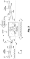
Fig. 2 is a cross-sectional view of the embodiment ofFig. 1 . - Reference will now be made to the drawings wherein like reference numerals identify similar structural features or aspects of the subject disclosure. For purposes of explanation and illustration, and not limitation, an illustrative view of an embodiment of a system in accordance with the disclosure is shown in
Fig. 1 and is designated generally byreference character 100. Other embodiments and/or aspects of this disclosure are shown inFig. 2 . - Referring to
Figs. 1 and2 , a gas knife system 100 (e.g., an air knife system) for an additive manufacturing system (e.g., as shown inFig, 1 ) can include one ormore rails system 100 can include aninlet manifold 103 configured to extend over a build area 105 (e.g., a build plate within an additive manufacturing system) and configured to be moveably (e.g., slideably) mounted to the one ormore rails build area 105. Thesystem 100 can include anoutlet manifold 107 configured to extend over thebuild area 105 and configured to be moveably mounted to the one ormore rails build area 105. - Any suitable motor system (e.g., any suitable belt drive system as appreciated by those having ordinary skill in the art in view of this disclosure) configured to allow the
inlet manifold 103 and theoutlet manifold 107 to move on therails manifolds rails - The
inlet manifold 103 and theoutlet manifold 107 can be configured to extend across an entire width of thebuild area 105, e.g., as shown. The one ormore rails rails build area 105. Theinlet manifold 103 and theoutlet manifold 107 are configured to slide on the tworails - The
inlet manifold 103 and theoutlet manifold 107 can be fixed in position relative to each other such that theinlet manifold 103 and theoutlet manifold 107 slide together and maintain a constant distance apart. In certain embodiments, theinlet manifold 103 and theoutlet manifold 107 are positioned parallel relative to each other, e.g., as shown. - The
inlet manifold 103 and/or theoutlet manifold 107 can have a flat shape with a high aspect ratio (e.g., long and thin with a small width as shown). As shown inFig. 2 , theinlet manifold 103 and/or theoutlet manifold 107 can include aninternal channel lateral opening inlet manifold 103 and/oroutlet manifold 107. - The
inlet manifold 103 and/or theoutlet manifold 107 can include a slot opening 103c, 107c sized to extend across an entire width of thebuild area 105 in fluid communication with theinternal channel inlet manifold 103 and/or theoutlet manifold 107 can be angled downward toward thebuild area 105, e.g., as shown inFig. 2 , such that the respective slot opening 103c, 107c is positioned closer to thebuild area 105 than an opposite side of therespective manifold 103, 107c. - In certain embodiments, the
inlet manifold 103 and/oroutlet manifold 107 include at least one of aspatter shield upper surface outlet manifold spatter shield 103d and/or 107d can be a solid material (e.g., sheet metal). However, embodiments of aspatter shield spatter shield 103d and/or 107d can include multiple flow sources/sinks connected thereto and/or a porous wall and/or any other suitable means to direct gas flow such that the velocity at different heights can be tailored. - The
inlet manifold 103 and/or theoutlet manifold 107 can include alip bottom surface inlet manifold 103 and/oroutlet manifold 107 beyond thespatter shield build area 105. Thelip 103f and/or 107f can be a solid piece of material (e.g., sheet metal) and/or any other suitable material. - The
inlet manifold 103 and theoutlet manifold 107 can be the same (e.g., positioned mirrored to each other), e.g., as shown. However, it is contemplated that theinlet manifold 103 and theoutlet manifold 107 can different in suitable manner, e.g., different shapes and/or channels and/or openings, different features, e.g.,inlet manifold 103 withspatter shield 103d and/orlip 103f and outlet manifold without one or both, or any other suitable difference. - A
recirculation system 109, e.g., closed loop, can be connected to each lateral end of each of theinlet manifold 103 andoutput manifold 107 to be in fluid communication with eachlateral opening inlet manifold 103 andoutlet manifold 107 to input flow to theoutput manifold 107 and receive return flow from theinlet manifold 103. Therecirculation system 109 can be connected to each lateral end of each manifold 103, 107, e.g., as shown, with aflexible hose manifolds recirculation system 109. Any other suitable connection type and/or position thereof to connect to themanifolds - In certain embodiments, the
system 100 can include acontrol module 111 configured to position theinlet manifold 103 and theoutlet manifold 107 relative to a location of amelt pool 113. Thecontrol module 111 can be configured to position theinlet manifold 103 and theoutlet manifold 107 such that themelt pool 113 is at a medial point between theinlet manifold 103 and theoutlet manifold 107, e.g., as shown. Thecontrol module 111 can be configured to move theinlet manifold 103 and theoutlet manifold 107 to follow movement of themelt pool 113. Any other suitable function for thecontrol module 111 is contemplated herein. Thecontrol module 111 can include any suitable hardware and/or software module(s). - The
control module 111 can form part of and/or be integrated with an additive manufacturing system controller, however, thecontrol module 111 can be separate or part of any other suitable system. In certain embodiments, thecontrol module 111 can receive a position of themelt pool 113 from the additive manufacturing system controller. Certain embodiments of acontrol module 111 can constantly move one or more of themanifolds manifolds manifolds - In accordance with at least one aspect of this disclosure, an additive manufacturing system can include a
build area 113, and a gas knife system, e.g., 100, as disclosed herein, e.g., as described above. Any other suitable components (e.g., a laser system, a powder recoater system or any other suitable material deposition system) are contemplated herein. - In accordance with at least one aspect of this disclosure, certain embodiment of a gas knife system for an additive manufacturing system can include one or more gas delivery members (e.g.,
inlet manifold 103 described above) configured to move relative to a build area of the additive manufacturing system, and an inlet conduit (e.g.,hose 109a described above) configured to supply gas to the one or more gas delivery members while the one or more gas delivery members are moved relative to the build area. Such an embodiment can also include one or more gas collection members (e.g. outlet manifold 107 as described above) configured to move relative to the build area of the additive manufacturing system, and an outlet conduit (e.g.,hose 109b as described above) configured collect gas from the one or more gas collection members while the one or more gas collection members move relative to the build area. - In accordance with at least one aspect of this disclosure, a method can include collecting spatter during an additive manufacturing operation using a moveable gas knife system. The method can include any other suitable method(s) and/or portion(s) thereof is contemplated herein.
- Certain embodiments can include an independent gantry system, e.g., using two strip shaped manifolds on rails that can move in a one dimension to follow where the melt pool is. Certain embodiments can be configured to maintain laminar flow at all times, e.g., by controlling a space between the manifolds to be within a laminar distance (e.g., about 100 mm or less). Certain embodiments can take data from a laser system to position the laser spot and the melt pool in the middle of space between the manifolds.
- Embodiments can include rails integrated into a wall, floor, or ceiling, of a chamber of an additive manufacturing machine. Embodiments can include a spatter shield extending upward on outlet nozzle, for example. Embodiments can include a lip (e.g., scoop shaped or straight) to prevent spatter from landing on the build area.
- In current systems, global gas flow direction generally acts 5-25 mm above the powder bed at a velocity of roughly 2-3 m/s, and is used to carry away the deposition products from above the melt pool such that the laser does not get scattered by them and they do not land back onto the part. Embodiments can replace the global gas flow across the whole plate with a similar gas flow profile sitting much closer to where melting is occurring.
- Traditional stationary gas knife systems only work over a limited distance. Embodiments include a gantry system and mechanism to generate local gas flow across a limited distance local to the melt pool. Embodiments can be moved around the build plate to cover the entire build area and can work for multiple lasers, eliminating the maximum build size threshold imposed by current gas flow technologies. One side of the system can have a gas jet from the inlet manifold, and the other would have suction in the outlet manifold, which can be part of a closed loop blower system.
- Efficient removal of deposition products generates parts with less defects. Embodiments allow a higher quality build and more build area to be utilized simultaneously, reducing cost and providing capability improvements.
- As will be appreciated by those skilled in the art, aspects of the present disclosure may be embodied as a system, method or computer program product. Accordingly, aspects of this disclosure may take the form of an entirely hardware embodiment, an entirely software embodiment (including firmware, resident software, micro-code, etc.), or an embodiment combining software and hardware aspects, all possibilities of which can be referred to herein as a "circuit," "module," or "system." A "circuit," "module," or "system" can include one or more portions of one or more separate physical hardware and/or software components that can together perform the disclosed function of the "circuit," "module," or "system", or a "circuit," "module," or "system" can be a single self-contained unit (e.g., of hardware and/or software). Furthermore, aspects of this disclosure may take the form of a computer program product embodied in one or more computer readable medium(s) having computer readable program code embodied thereon.
- Any combination of one or more computer readable medium(s) may be utilized. The computer readable medium may be a computer readable signal medium or a computer readable storage medium. A computer readable storage medium may be, for example, but not limited to, an electronic, magnetic, optical, electromagnetic, infrared, or semiconductor system, apparatus, or device, or any suitable combination of the foregoing. More specific examples (a non-exhaustive list) of the computer readable storage medium would include the following: an electrical connection having one or more wires, a portable computer diskette, a hard disk, a random access memory (RAM), a read-only memory (ROM), an erasable programmable read-only memory (EPROM or Flash memory), an optical fiber, a portable compact disc read-only memory (CD-ROM), an optical storage device, a magnetic storage device, or any suitable combination of the foregoing. In the context of this document, a computer readable storage medium may be any tangible medium that can contain, or store a program for use by or in connection with an instruction execution system, apparatus, or device.
- A computer readable signal medium may include a propagated data signal with computer readable program code embodied therein, for example, in baseband or as part of a carrier wave. Such a propagated signal may take any of a variety of forms, including, but not limited to, electro-magnetic, optical, or any suitable combination thereof. A computer readable signal medium may be any computer readable medium that is not a computer readable storage medium and that can communicate, propagate, or transport a program for use by or in connection with an instruction execution system, apparatus, or device.
- Program code embodied on a computer readable medium may be transmitted using any appropriate medium, including but not limited to wireless, wireline, optical fiber cable, RF, etc., or any suitable combination of the foregoing.
- Computer program code for carrying out operations for aspects of this disclosure may be written in any combination of one or more programming languages, including an object oriented programming language such as Java, Smalltalk, C++ or the like and conventional procedural programming languages, such as the "C" programming language or similar programming languages. The program code may execute entirely on the user's computer, partly on the user's computer, as a stand-alone software package, partly on the user's computer and partly on a remote computer or entirely on the remote computer or server. In the latter scenario, the remote computer may be connected to the user's computer through any type of network, including a local area network (LAN) or a wide area network (WAN), or the connection may be made to an external computer (for example, through the Internet using an Internet Service Provider).
- Aspects of the this disclosure may be described above with reference to flowchart illustrations and/or block diagrams of methods, apparatus (systems) and computer program products according to embodiments of this disclosure. It will be understood that each block of any flowchart illustrations and/or block diagrams, and combinations of blocks in any flowchart illustrations and/or block diagrams, can be implemented by computer program instructions. These computer program instructions may be provided to a processor of a general purpose computer, special purpose computer, or other programmable data processing apparatus to produce a machine, such that the instructions, which execute via the processor of the computer or other programmable data processing apparatus, create means for implementing the functions/acts specified in any flowchart and/or block diagram block or blocks.
- These computer program instructions may also be stored in a computer readable medium that can direct a computer, other programmable data processing apparatus, or other devices to function in a particular manner, such that the instructions stored in the computer readable medium produce an article of manufacture including instructions which implement the function/act specified in the flowchart and/or block diagram block or blocks.
- The computer program instructions may also be loaded onto a computer, other programmable data processing apparatus, or other devices to cause a series of operational steps to be performed on the computer, other programmable apparatus or other devices to produce a computer implemented process such that the instructions which execute on the computer or other programmable apparatus provide processes for implementing the functions/acts specified herein.
- Those having ordinary skill in the art understand that any numerical values disclosed herein can be exact values or can be values within a range. Further, any terms of approximation (e.g., "about", "approximately", "around") used in this disclosure can mean the stated value within a range. For example, in certain embodiments, the range can be within (plus or minus) 20%, or within 10%, or within 5%, or within 2%, or within any other suitable percentage or number as appreciated by those having ordinary skill in the art (e.g., for known tolerance limits or error ranges).
- The articles "a", "an", and "the" as used herein and in the appended claims are used herein to refer to one or to more than one (i.e., to at least one) of the grammatical object of the article unless the context clearly indicates otherwise. By way of example, "an element" means one element or more than one element.
- The phrase "and/or," as used herein in the specification and in the claims, should be understood to mean "either or both" of the elements so conjoined, i.e., elements that are conjunctively present in some cases and disjunctively present in other cases. Multiple elements listed with "and/or" should be construed in the same fashion, i.e., "one or more" of the elements so conjoined. Other elements may optionally be present other than the elements specifically identified by the "and/or" clause, whether related or unrelated to those elements specifically identified. Thus, as a non-limiting example, a reference to "A and/or B", when used in conjunction with open-ended language such as "comprising" can refer, in one embodiment, to A only (optionally including elements other than B); in another embodiment, to B only (optionally including elements other than A); in yet another embodiment, to both A and B (optionally including other elements); etc.
- As used herein in the specification and in the claims, "or" should be understood to have the same meaning as "and/or" as defined above. For example, when separating items in a list, "or" or "and/or" shall be interpreted as being inclusive, i.e., the inclusion of at least one, but also including more than one, of a number or list of elements, and, optionally, additional unlisted items. Only terms clearly indicated to the contrary, such as "only one of' or "exactly one of," or, when used in the claims, "consisting of," will refer to the inclusion of exactly one element of a number or list of elements. In general, the term "or" as used herein shall only be interpreted as indicating exclusive alternatives (i.e., "one or the other but not both") when preceded by terms of exclusivity, such as "either," "one of," "only one of," or "exactly one of."
- Any suitable combination(s) of any disclosed embodiments and/or any suitable portion(s) thereof are contemplated herein as appreciated by those having ordinary skill in the art in view of this disclosure.
- The embodiments of the present disclosure, as described above and shown in the drawings, provide for improvement in the art to which they pertain. While the subject disclosure includes reference to certain embodiments, those skilled in the art will readily appreciate that changes and/or modifications may be made thereto without departing from the spirit and scope of the subject disclosure.
Claims (15)
- A gas knife system (100) for an additive manufacturing system, comprising:one or more gas delivery members configured to move relative to a build area of the additive manufacturing system;an inlet conduit (109a) configured to supply gas to the one or more gas delivery members while the one or more gas delivery members are moved relative to the build area;one or more gas collection members (107) configured to move relative to the build area of the additive manufacturing system; andan outlet conduit (109b) configured collect gas from the one or more gas collection members while the one or more gas collection members move relative to the build area.
- A gas knife system for an additive manufacturing system, comprising:one or more rails (101z, 101b) configured to be disposed in an additive manufacturing system and/or forming part of the additive manufacturing system;an inlet manifold (103) configured to extend over a build area and configured to be moveably mounted to the one or more rails to move relative to the build area; andan outlet manifold (107) configured to extend over the build area and configured to be moveably mounted to the one or more rails to move relative to the build area.
- The system of claim 2, wherein the inlet manifold and the outlet manifold are configured to extend across an entire width of the build area.
- The system of claim 3, wherein the one or more rails includes two rails configured to be on opposite sides of the build area, wherein the inlet manifold and the outlet manifold are configured to slide on the two rails.
- The system of claim 4, wherein the inlet manifold and the outlet manifold are fixed in position relative to each other such that the inlet manifold and the outlet manifold slide together and maintain a constant distance apart.
- The system of claim 5, wherein the inlet manifold and the outlet manifold are positioned parallel relative to each other.
- The system of claim 6, wherein the inlet manifold and/or the outlet manifold have a flat shape with a high aspect ratio.
- The system of claim 7, wherein the inlet manifold and/or the outlet manifold include an internal channel defined therein and in fluid communication with a lateral opening on a lateral end of the inlet manifold and/or outlet manifold.
- The system of claim 8, wherein the inlet manifold and/or the outlet manifold include a slot opening sized to extend across an entire width of the build area in fluid communication with the internal channel.
- The system of claim 9, wherein the inlet manifold and/or the outlet manifold is/are angled downward toward the build area such that each slot opening is positioned closer to the build area than an opposite side of the respective manifold, and optionally
wherein the inlet manifold and/or outlet manifold include at least one of a spatter shield extending at least partially upward from an upper surface of the inlet and/or outlet manifold, and optionally
wherein the inlet manifold and/or the outlet manifold include a lip extending from a bottom surface of the inlet manifold and/or outlet manifold beyond the spatter shield toward the build area. - The system of claim 8, further comprising a recirculation system connected to each lateral end of each of the inlet manifold and output manifold to be in fluid communication with each lateral opening of the inlet manifold and outlet manifold to input flow to the output manifold and receive return flow from the inlet manifold, and optionally wherein the recirculation system is connected to each lateral end of each manifold with a flexible hose to allow the manifolds to move relative to the recirculation system.
- The system of claim 2, further comprising a control module configured to position the inlet manifold and the outlet manifold relative to a location of a melt pool.
- The system of claim 12, wherein the control module is configured to position the inlet manifold and the outlet manifold such that the melt pool is at a medial point between the inlet manifold and the outlet manifold, and optionally
wherein the control module is configured to move the inlet manifold and the outlet manifold to follow movement of the melt pool. - The system of claim 2, further comprising the additive manufacturing system and the build area, and optionally wherein the inlet manifold and the outlet manifold are configured to extend across an entire width of the build area, wherein the one or more rails includes two rails configured to be on opposite sides of the build area, wherein the inlet manifold and the outlet manifold are configured to slide on the two rails.
- A method, comprising:
collecting spatter during an additive manufacturing operation using a moveable gas knife system.
Applications Claiming Priority (1)
| Application Number | Priority Date | Filing Date | Title |
|---|---|---|---|
| US16/593,727 US11745228B2 (en) | 2019-10-04 | 2019-10-04 | Air knife systems |
Publications (2)
| Publication Number | Publication Date |
|---|---|
| EP3800406A1 true EP3800406A1 (en) | 2021-04-07 |
| EP3800406B1 EP3800406B1 (en) | 2025-10-22 |
Family
ID=68886852
Family Applications (1)
| Application Number | Title | Priority Date | Filing Date |
|---|---|---|---|
| EP19215268.4A Active EP3800406B1 (en) | 2019-10-04 | 2019-12-11 | Air knife systems |
Country Status (2)
| Country | Link |
|---|---|
| US (1) | US11745228B2 (en) |
| EP (1) | EP3800406B1 (en) |
Families Citing this family (1)
| Publication number | Priority date | Publication date | Assignee | Title |
|---|---|---|---|---|
| US20250073779A1 (en) * | 2023-09-06 | 2025-03-06 | GM Global Technology Operations LLC | System for additive manufacturing having a movable outlet |
Citations (5)
| Publication number | Priority date | Publication date | Assignee | Title |
|---|---|---|---|---|
| WO2014199150A1 (en) * | 2013-06-11 | 2014-12-18 | Renishaw Plc | Additive manufacturing apparatus and method |
| DE102013215377A1 (en) * | 2013-08-05 | 2015-02-05 | Bayerische Motoren Werke Aktiengesellschaft | Gas guiding device, device for producing a component by application of powder layers and method for supplying and extracting gas in such a device |
| DE102014209161A1 (en) * | 2014-05-14 | 2015-11-19 | Eos Gmbh Electro Optical Systems | Control unit, apparatus and method for producing a three-dimensional object |
| WO2017179001A1 (en) * | 2016-04-13 | 2017-10-19 | 3D New Technologies S.R.L. | Apparatus for additive manufacturing and method of additive manufacturing |
| JP2018003148A (en) * | 2016-06-27 | 2018-01-11 | ナブテスコ株式会社 | Shaping device |
Family Cites Families (7)
| Publication number | Priority date | Publication date | Assignee | Title |
|---|---|---|---|---|
| US3215350A (en) * | 1964-01-27 | 1965-11-02 | Robert E Hetrick | Protective-shield-defining, debrisdeflecting air gun nozzle |
| US5386500A (en) * | 1987-06-02 | 1995-01-31 | Cubital Ltd. | Three dimensional modeling apparatus |
| DE19649865C1 (en) | 1996-12-02 | 1998-02-12 | Fraunhofer Ges Forschung | Shaped body especially prototype or replacement part production |
| GB201410484D0 (en) | 2014-06-12 | 2014-07-30 | Renishaw Plc | Additive manufacturing apparatus and a flow device for use with such apparatus |
| US10189057B2 (en) | 2016-07-08 | 2019-01-29 | General Electric Company | Powder removal enclosure for additively manufactured components |
| US11014304B2 (en) * | 2018-04-24 | 2021-05-25 | General Electric Company | Additive manufacturing system and method |
| CN112334295B (en) * | 2018-06-01 | 2022-09-06 | 应用材料公司 | Air knife for additive manufacturing |
-
2019
- 2019-10-04 US US16/593,727 patent/US11745228B2/en active Active
- 2019-12-11 EP EP19215268.4A patent/EP3800406B1/en active Active
Patent Citations (5)
| Publication number | Priority date | Publication date | Assignee | Title |
|---|---|---|---|---|
| WO2014199150A1 (en) * | 2013-06-11 | 2014-12-18 | Renishaw Plc | Additive manufacturing apparatus and method |
| DE102013215377A1 (en) * | 2013-08-05 | 2015-02-05 | Bayerische Motoren Werke Aktiengesellschaft | Gas guiding device, device for producing a component by application of powder layers and method for supplying and extracting gas in such a device |
| DE102014209161A1 (en) * | 2014-05-14 | 2015-11-19 | Eos Gmbh Electro Optical Systems | Control unit, apparatus and method for producing a three-dimensional object |
| WO2017179001A1 (en) * | 2016-04-13 | 2017-10-19 | 3D New Technologies S.R.L. | Apparatus for additive manufacturing and method of additive manufacturing |
| JP2018003148A (en) * | 2016-06-27 | 2018-01-11 | ナブテスコ株式会社 | Shaping device |
Also Published As
| Publication number | Publication date |
|---|---|
| EP3800406B1 (en) | 2025-10-22 |
| US20210101186A1 (en) | 2021-04-08 |
| US11745228B2 (en) | 2023-09-05 |
Similar Documents
| Publication | Publication Date | Title |
|---|---|---|
| US10434574B2 (en) | Laminating and shaping apparatus | |
| CN105492157B (en) | Method for continuously conveying and butt-welding sheet metal pieces and use of said method | |
| JP6962622B2 (en) | Gas flow system for additive manufacturing equipment | |
| US10166603B2 (en) | Metal 3D printer | |
| US3761675A (en) | Material cutting and printing system | |
| US9505096B2 (en) | Machining tools, waste removal devices, and related methods | |
| US11548180B2 (en) | Systems and methods for shaping and cutting materials | |
| KR102329564B1 (en) | Laser machining device for machining workpieces by means of a laser | |
| EP3800406B1 (en) | Air knife systems | |
| CN111298542A (en) | Gas circulator and lamination processing device | |
| JP6240477B2 (en) | Dust collector for thermal processing machine | |
| CN109604596B (en) | Additive manufacturing dynamic powder laying system | |
| JP2019130556A (en) | Laser welding device | |
| JP5995652B2 (en) | Airflow control method and airflow control device for welding work room | |
| CN217412832U (en) | Laser cutting slitting device | |
| JPH03275292A (en) | Laser beam machine | |
| JP6792728B2 (en) | Laser blanking device | |
| JPH08132228A (en) | Surface plate | |
| CN117884655B (en) | 3D printer and control method thereof | |
| CN109414786B (en) | engine room | |
| CN216858630U (en) | Battery pole piece processing device and processing equipment | |
| CN213531216U (en) | Laser processing equipment and its machine tool bed structure | |
| JPH11314190A (en) | Laser beam machining device and dust collecting method | |
| JP2020015063A (en) | Laser processing machine | |
| US20210016392A1 (en) | Waste product removal systems |
Legal Events
| Date | Code | Title | Description |
|---|---|---|---|
| PUAI | Public reference made under article 153(3) epc to a published international application that has entered the european phase |
Free format text: ORIGINAL CODE: 0009012 |
|
| STAA | Information on the status of an ep patent application or granted ep patent |
Free format text: STATUS: THE APPLICATION HAS BEEN PUBLISHED |
|
| AK | Designated contracting states |
Kind code of ref document: A1 Designated state(s): AL AT BE BG CH CY CZ DE DK EE ES FI FR GB GR HR HU IE IS IT LI LT LU LV MC MK MT NL NO PL PT RO RS SE SI SK SM TR |
|
| AX | Request for extension of the european patent |
Extension state: BA ME |
|
| STAA | Information on the status of an ep patent application or granted ep patent |
Free format text: STATUS: REQUEST FOR EXAMINATION WAS MADE |
|
| 17P | Request for examination filed |
Effective date: 20211007 |
|
| RBV | Designated contracting states (corrected) |
Designated state(s): AL AT BE BG CH CY CZ DE DK EE ES FI FR GB GR HR HU IE IS IT LI LT LU LV MC MK MT NL NO PL PT RO RS SE SI SK SM TR |
|
| STAA | Information on the status of an ep patent application or granted ep patent |
Free format text: STATUS: EXAMINATION IS IN PROGRESS |
|
| 17Q | First examination report despatched |
Effective date: 20230814 |
|
| GRAP | Despatch of communication of intention to grant a patent |
Free format text: ORIGINAL CODE: EPIDOSNIGR1 |
|
| STAA | Information on the status of an ep patent application or granted ep patent |
Free format text: STATUS: GRANT OF PATENT IS INTENDED |
|
| RIC1 | Information provided on ipc code assigned before grant |
Ipc: B33Y 40/00 20200101ALI20250417BHEP Ipc: B33Y 30/00 20150101ALI20250417BHEP Ipc: B29C 64/35 20170101ALI20250417BHEP Ipc: B23K 26/142 20140101ALI20250417BHEP Ipc: B29C 64/364 20170101ALI20250417BHEP Ipc: F24F 9/00 20060101AFI20250417BHEP |
|
| RIN1 | Information on inventor provided before grant (corrected) |
Inventor name: MORGANSON, DAVID W. Inventor name: FISHER, BRIAN A. |
|
| INTG | Intention to grant announced |
Effective date: 20250514 |
|
| GRAS | Grant fee paid |
Free format text: ORIGINAL CODE: EPIDOSNIGR3 |
|
| GRAA | (expected) grant |
Free format text: ORIGINAL CODE: 0009210 |
|
| STAA | Information on the status of an ep patent application or granted ep patent |
Free format text: STATUS: THE PATENT HAS BEEN GRANTED |
|
| AK | Designated contracting states |
Kind code of ref document: B1 Designated state(s): AL AT BE BG CH CY CZ DE DK EE ES FI FR GB GR HR HU IE IS IT LI LT LU LV MC MK MT NL NO PL PT RO RS SE SI SK SM TR |
|
| REG | Reference to a national code |
Ref country code: CH Ref legal event code: F10 Free format text: ST27 STATUS EVENT CODE: U-0-0-F10-F00 (AS PROVIDED BY THE NATIONAL OFFICE) Effective date: 20251022 Ref country code: GB Ref legal event code: FG4D |
|
| REG | Reference to a national code |
Ref country code: DE Ref legal event code: R096 Ref document number: 602019077103 Country of ref document: DE |
|
| REG | Reference to a national code |
Ref country code: IE Ref legal event code: FG4D |
|
| PGFP | Annual fee paid to national office [announced via postgrant information from national office to epo] |
Ref country code: DE Payment date: 20251126 Year of fee payment: 7 |
|
| PGFP | Annual fee paid to national office [announced via postgrant information from national office to epo] |
Ref country code: GB Payment date: 20251119 Year of fee payment: 7 |
|
| PGFP | Annual fee paid to national office [announced via postgrant information from national office to epo] |
Ref country code: FR Payment date: 20251120 Year of fee payment: 7 |
|
| REG | Reference to a national code |
Ref country code: NL Ref legal event code: MP Effective date: 20251022 |
|
| PG25 | Lapsed in a contracting state [announced via postgrant information from national office to epo] |
Ref country code: NL Free format text: LAPSE BECAUSE OF FAILURE TO SUBMIT A TRANSLATION OF THE DESCRIPTION OR TO PAY THE FEE WITHIN THE PRESCRIBED TIME-LIMIT Effective date: 20251022 |
|
| PG25 | Lapsed in a contracting state [announced via postgrant information from national office to epo] |
Ref country code: ES Free format text: LAPSE BECAUSE OF FAILURE TO SUBMIT A TRANSLATION OF THE DESCRIPTION OR TO PAY THE FEE WITHIN THE PRESCRIBED TIME-LIMIT Effective date: 20251022 |
|
| REG | Reference to a national code |
Ref country code: LT Ref legal event code: MG9D |
|
| PG25 | Lapsed in a contracting state [announced via postgrant information from national office to epo] |
Ref country code: NO Free format text: LAPSE BECAUSE OF FAILURE TO SUBMIT A TRANSLATION OF THE DESCRIPTION OR TO PAY THE FEE WITHIN THE PRESCRIBED TIME-LIMIT Effective date: 20260122 |
|
| PG25 | Lapsed in a contracting state [announced via postgrant information from national office to epo] |
Ref country code: AT Free format text: LAPSE BECAUSE OF FAILURE TO SUBMIT A TRANSLATION OF THE DESCRIPTION OR TO PAY THE FEE WITHIN THE PRESCRIBED TIME-LIMIT Effective date: 20251022 Ref country code: FI Free format text: LAPSE BECAUSE OF FAILURE TO SUBMIT A TRANSLATION OF THE DESCRIPTION OR TO PAY THE FEE WITHIN THE PRESCRIBED TIME-LIMIT Effective date: 20251022 Ref country code: HR Free format text: LAPSE BECAUSE OF FAILURE TO SUBMIT A TRANSLATION OF THE DESCRIPTION OR TO PAY THE FEE WITHIN THE PRESCRIBED TIME-LIMIT Effective date: 20251022 |
|
| REG | Reference to a national code |
Ref country code: AT Ref legal event code: MK05 Ref document number: 1849439 Country of ref document: AT Kind code of ref document: T Effective date: 20251022 |
|
| PG25 | Lapsed in a contracting state [announced via postgrant information from national office to epo] |
Ref country code: RS Free format text: LAPSE BECAUSE OF FAILURE TO SUBMIT A TRANSLATION OF THE DESCRIPTION OR TO PAY THE FEE WITHIN THE PRESCRIBED TIME-LIMIT Effective date: 20260122 |
|
| PG25 | Lapsed in a contracting state [announced via postgrant information from national office to epo] |
Ref country code: IS Free format text: LAPSE BECAUSE OF FAILURE TO SUBMIT A TRANSLATION OF THE DESCRIPTION OR TO PAY THE FEE WITHIN THE PRESCRIBED TIME-LIMIT Effective date: 20260222 |
|
| PG25 | Lapsed in a contracting state [announced via postgrant information from national office to epo] |
Ref country code: PT Free format text: LAPSE BECAUSE OF FAILURE TO SUBMIT A TRANSLATION OF THE DESCRIPTION OR TO PAY THE FEE WITHIN THE PRESCRIBED TIME-LIMIT Effective date: 20260223 |
|
| PG25 | Lapsed in a contracting state [announced via postgrant information from national office to epo] |
Ref country code: PL Free format text: LAPSE BECAUSE OF FAILURE TO SUBMIT A TRANSLATION OF THE DESCRIPTION OR TO PAY THE FEE WITHIN THE PRESCRIBED TIME-LIMIT Effective date: 20251022 |
|
| PG25 | Lapsed in a contracting state [announced via postgrant information from national office to epo] |
Ref country code: LV Free format text: LAPSE BECAUSE OF FAILURE TO SUBMIT A TRANSLATION OF THE DESCRIPTION OR TO PAY THE FEE WITHIN THE PRESCRIBED TIME-LIMIT Effective date: 20251022 |
|
| PG25 | Lapsed in a contracting state [announced via postgrant information from national office to epo] |
Ref country code: BG Free format text: LAPSE BECAUSE OF FAILURE TO SUBMIT A TRANSLATION OF THE DESCRIPTION OR TO PAY THE FEE WITHIN THE PRESCRIBED TIME-LIMIT Effective date: 20251022 |