EP3800379A1 - Static curvic joint for epicyclical gear system housing assembly - Google Patents
Static curvic joint for epicyclical gear system housing assembly Download PDFInfo
- Publication number
- EP3800379A1 EP3800379A1 EP20194254.7A EP20194254A EP3800379A1 EP 3800379 A1 EP3800379 A1 EP 3800379A1 EP 20194254 A EP20194254 A EP 20194254A EP 3800379 A1 EP3800379 A1 EP 3800379A1
- Authority
- EP
- European Patent Office
- Prior art keywords
- aft
- gear
- planet
- shaft
- flange
- Prior art date
- Legal status (The legal status is an assumption and is not a legal conclusion. Google has not performed a legal analysis and makes no representation as to the accuracy of the status listed.)
- Withdrawn
Links
Images





Classifications
-
- F—MECHANICAL ENGINEERING; LIGHTING; HEATING; WEAPONS; BLASTING
- F16—ENGINEERING ELEMENTS AND UNITS; GENERAL MEASURES FOR PRODUCING AND MAINTAINING EFFECTIVE FUNCTIONING OF MACHINES OR INSTALLATIONS; THERMAL INSULATION IN GENERAL
- F16H—GEARING
- F16H1/00—Toothed gearings for conveying rotary motion
- F16H1/28—Toothed gearings for conveying rotary motion with gears having orbital motion
- F16H1/2809—Toothed gearings for conveying rotary motion with gears having orbital motion with means for equalising the distribution of load on the planet gears
- F16H1/2827—Toothed gearings for conveying rotary motion with gears having orbital motion with means for equalising the distribution of load on the planet gears by allowing limited movement of the planet carrier, e.g. relative to its shaft
-
- F—MECHANICAL ENGINEERING; LIGHTING; HEATING; WEAPONS; BLASTING
- F02—COMBUSTION ENGINES; HOT-GAS OR COMBUSTION-PRODUCT ENGINE PLANTS
- F02C—GAS-TURBINE PLANTS; AIR INTAKES FOR JET-PROPULSION PLANTS; CONTROLLING FUEL SUPPLY IN AIR-BREATHING JET-PROPULSION PLANTS
- F02C7/00—Features, components parts, details or accessories, not provided for in, or of interest apart form groups F02C1/00 - F02C6/00; Air intakes for jet-propulsion plants
- F02C7/36—Power transmission arrangements between the different shafts of the gas turbine plant, or between the gas-turbine plant and the power user
-
- F—MECHANICAL ENGINEERING; LIGHTING; HEATING; WEAPONS; BLASTING
- F02—COMBUSTION ENGINES; HOT-GAS OR COMBUSTION-PRODUCT ENGINE PLANTS
- F02K—JET-PROPULSION PLANTS
- F02K3/00—Plants including a gas turbine driving a compressor or a ducted fan
- F02K3/02—Plants including a gas turbine driving a compressor or a ducted fan in which part of the working fluid by-passes the turbine and combustion chamber
- F02K3/04—Plants including a gas turbine driving a compressor or a ducted fan in which part of the working fluid by-passes the turbine and combustion chamber the plant including ducted fans, i.e. fans with high volume, low pressure outputs, for augmenting the jet thrust, e.g. of double-flow type
- F02K3/06—Plants including a gas turbine driving a compressor or a ducted fan in which part of the working fluid by-passes the turbine and combustion chamber the plant including ducted fans, i.e. fans with high volume, low pressure outputs, for augmenting the jet thrust, e.g. of double-flow type with front fan
-
- F—MECHANICAL ENGINEERING; LIGHTING; HEATING; WEAPONS; BLASTING
- F16—ENGINEERING ELEMENTS AND UNITS; GENERAL MEASURES FOR PRODUCING AND MAINTAINING EFFECTIVE FUNCTIONING OF MACHINES OR INSTALLATIONS; THERMAL INSULATION IN GENERAL
- F16H—GEARING
- F16H1/00—Toothed gearings for conveying rotary motion
- F16H1/28—Toothed gearings for conveying rotary motion with gears having orbital motion
-
- F—MECHANICAL ENGINEERING; LIGHTING; HEATING; WEAPONS; BLASTING
- F16—ENGINEERING ELEMENTS AND UNITS; GENERAL MEASURES FOR PRODUCING AND MAINTAINING EFFECTIVE FUNCTIONING OF MACHINES OR INSTALLATIONS; THERMAL INSULATION IN GENERAL
- F16H—GEARING
- F16H1/00—Toothed gearings for conveying rotary motion
- F16H1/28—Toothed gearings for conveying rotary motion with gears having orbital motion
- F16H1/2863—Arrangements for adjusting or for taking-up backlash
-
- F—MECHANICAL ENGINEERING; LIGHTING; HEATING; WEAPONS; BLASTING
- F16—ENGINEERING ELEMENTS AND UNITS; GENERAL MEASURES FOR PRODUCING AND MAINTAINING EFFECTIVE FUNCTIONING OF MACHINES OR INSTALLATIONS; THERMAL INSULATION IN GENERAL
- F16H—GEARING
- F16H57/00—General details of gearing
- F16H57/08—General details of gearing of gearings with members having orbital motion
-
- F—MECHANICAL ENGINEERING; LIGHTING; HEATING; WEAPONS; BLASTING
- F16—ENGINEERING ELEMENTS AND UNITS; GENERAL MEASURES FOR PRODUCING AND MAINTAINING EFFECTIVE FUNCTIONING OF MACHINES OR INSTALLATIONS; THERMAL INSULATION IN GENERAL
- F16H—GEARING
- F16H57/00—General details of gearing
- F16H57/08—General details of gearing of gearings with members having orbital motion
- F16H57/082—Planet carriers
-
- F—MECHANICAL ENGINEERING; LIGHTING; HEATING; WEAPONS; BLASTING
- F05—INDEXING SCHEMES RELATING TO ENGINES OR PUMPS IN VARIOUS SUBCLASSES OF CLASSES F01-F04
- F05D—INDEXING SCHEME FOR ASPECTS RELATING TO NON-POSITIVE-DISPLACEMENT MACHINES OR ENGINES, GAS-TURBINES OR JET-PROPULSION PLANTS
- F05D2260/00—Function
- F05D2260/40—Transmission of power
- F05D2260/403—Transmission of power through the shape of the drive components
- F05D2260/4031—Transmission of power through the shape of the drive components as in toothed gearing
- F05D2260/40311—Transmission of power through the shape of the drive components as in toothed gearing of the epicyclical, planetary or differential type
-
- F—MECHANICAL ENGINEERING; LIGHTING; HEATING; WEAPONS; BLASTING
- F16—ENGINEERING ELEMENTS AND UNITS; GENERAL MEASURES FOR PRODUCING AND MAINTAINING EFFECTIVE FUNCTIONING OF MACHINES OR INSTALLATIONS; THERMAL INSULATION IN GENERAL
- F16H—GEARING
- F16H1/00—Toothed gearings for conveying rotary motion
- F16H1/28—Toothed gearings for conveying rotary motion with gears having orbital motion
- F16H2001/2881—Toothed gearings for conveying rotary motion with gears having orbital motion comprising two axially spaced central gears, i.e. ring or sun gear, engaged by at least one common orbital gear wherein one of the central gears is forming the output
-
- Y—GENERAL TAGGING OF NEW TECHNOLOGICAL DEVELOPMENTS; GENERAL TAGGING OF CROSS-SECTIONAL TECHNOLOGIES SPANNING OVER SEVERAL SECTIONS OF THE IPC; TECHNICAL SUBJECTS COVERED BY FORMER USPC CROSS-REFERENCE ART COLLECTIONS [XRACs] AND DIGESTS
- Y02—TECHNOLOGIES OR APPLICATIONS FOR MITIGATION OR ADAPTATION AGAINST CLIMATE CHANGE
- Y02T—CLIMATE CHANGE MITIGATION TECHNOLOGIES RELATED TO TRANSPORTATION
- Y02T50/00—Aeronautics or air transport
- Y02T50/60—Efficient propulsion technologies, e.g. for aircraft
Definitions
- the present disclosure relates to epicyclic gear systems for gas turbine engines, more particularly to a planet gear housing assembly for an epicyclical gear assembly.
- Epicyclical gear systems may be used in rotating machinery to transfer energy from one component, such as a rotatable shaft, to another.
- an epicyclical gear system may be designed to transfer energy between components at a desired ratio and often convert a high-speed, low-torque input to a lower-speed, higher-torque output.
- Epicyclical gear systems may be suitable for a wide range of applications, including the transfer of energy from a turbine shaft to a fan rotor in a geared turbofan engine.
- the epicyclical gear system must be designed to allow some degree of relative movement between parts of the system to avoid excessive wear and, in extreme conditions, system failure.
- the present disclosure provides a planet gear housing assembly for an epicyclical gear assembly, and a gas turbine engines, as set out in the appended claims.
- a planet gear housing assembly for an epicyclical gear assembly comprises an aft planet carrier assembly, a forward planet carrier assembly, and a plurality of planet gears.
- the aft planet carrier assembly comprises an aft flange and an annular mounting flange.
- the aft flange defines a central aperture and a plurality of gear shaft pockets positioned about the circumference and radially outward of the central aperture, each pocket having a cylindrical wall.
- the annular mounting flange is positioned forward of and coaxial with the central aperture and forms a forward facing mounting surface comprising a curvic structure.
- the forward planet carrier assembly comprises a forward flange and an annular mounting flange.
- the forward flange defines a central aperture and a plurality of gear shaft pockets positioned about the circumference and radially outward of the central aperture, each pocket having a cylindrical wall.
- the annular mounting flange is positioned aft of and coaxial with the central aperture and forms an aft facing mounting surface comprising a curvic structure.
- the plurality of planet gears each comprise a cylindrical shaft having a forward end portion disposed in a gear shaft pocket of the forward planet carrier assembly coaxially with the cylindrical wall of the pocket, an aft end portion disposed within a gear shaft pocket of the aft planet carrier assembly coaxially with the cylindrical wall of the pocket, and one or more gears carried by the shaft between the forward and aft end portions.
- the curvic structures of the mounting surfaces are positioned relative to each other to thereby form a static curvic joint.
- annular mounting flange of the aft planet carrier assembly extends from the aft flange. In some embodiments the annular mounting flange of the forward planet carrier assembly extends from the forward flange. In some embodiments one or both of the annular mounting flange of the aft planet carrier assembly and the annular mounting flange of the forward planet carrier assembly extends substantially perpendicularly from a respective one of the aft flange and the forward flange.
- the aft flange comprises a radially outer mounting surface for mounting the planet gear housing assembly to an engine casing.
- the curvic structure of the aft facing mounting surface comprises a plurality of teeth extending away from the aft facing mounting surface.
- the aft facing mounting surface defines a plurality of fastener bores, with each fastener bore of the plurality of fastener bores positioned between adjacent teeth of the plurality of teeth.
- the curvic structure of the forward facing mounting surface comprises a plurality of teeth extending away from the forward facing mounting surface.
- the forward facing mounting surface defines a plurality of fastener bores, with each fastener bore of the plurality of fastener bores positioned between adjacent teeth of the plurality of teeth.
- the static curvic joint comprises the plurality of teeth extending away from the aft facing mounting surface enmeshed with the plurality of teeth extending away from the forward facing mounting surface.
- the static curvic joint further comprises a plurality of fasteners, with each fastener of the plurality of fasteners positioned through an aligned pair of fastener bores.
- a gas turbine engine for an aircraft comprises an engine core, a fan, and a gearbox.
- the engine core comprises a turbine, a compressor, and a core shaft connecting the turbine to the compressor.
- the fan is located upstream of the engine core and comprises a plurality of fan blades.
- the gearbox receives an input from the core shaft and outputs drive to the fan so as to drive the fan at a lower rotational speed than the core shaft.
- the gearbox has a planet gear housing assembly of the first aspect.
- each of the plurality of planet gears comprise a sun gear engaging gear and a ring gear engaging gear carried by the shaft between the forward and aft end portions.
- the shaft and gears form a compound star gear in an epicyclical gear system.
- the gearbox further comprises a roller element bearing disposed over at least a portion of one or both of the forward end portion and the aft end portion of the gear shaft.
- the curvic structure of the aft facing mounting surface and the forward facing mounting surface each comprise a plurality of teeth extending away from the respective one of the aft facing mounting surface and the forward facing mounting surface.
- the method comprises providing a static aft planet carrier assembly, providing a static forward planet carrier assembly, and coupling the aft planet carrier assembly and forward planet carrier assembly.
- the static aft planet carrier assembly comprises an aft flange defining a central aperture and an annular mounting flange positioned forward of and coaxial with the central aperture.
- the mounting flange forms a forward facing mounting surface comprising a curvic structure.
- the static forward planet carrier assembly comprises a forward flange defining a central aperture and an annular mounting flange positioned aft of and coaxial with the central aperture.
- the mounting flange forms an aft facing mounting surface comprising a curvic structure.
- the aft planet carrier assembly and the forward planet carrier assembly are coupled by mating the curvic structure of the forward facing mounting surface to the curvic structure of the aft facing mounting surface to thereby form a static curvic joint.
- the aft flange further defines a plurality of gear shaft pockets positioned about the circumference and radially outward of the central aperture, each pocket having a cylindrical wall.
- the forward flange further defines a plurality of gear shaft pockets positioned about the circumference and radially outward of the central aperture, each pocket having a cylindrical wall.
- the coupling of the aft planet carrier assembly and the forward planet carrier assembly forms a plurality of axially aligned gear shaft pocket pairs.
- the method of further comprises positioning one planet gear of a plurality of planet gears in each of the plurality of axially aligned gear shaft pocket pairs, each planet gear comprising a cylindrical shaft having a forward end portion disposed in a gear shaft pocket of the forward planet carrier assembly coaxially with the cylindrical wall of the pocket, an aft end portion disposed within a gear shaft pocket of the aft planet carrier assembly coaxially with the cylindrical wall of the pocket, and one or more gears carried by the shaft between the forward and aft end portions.
- the method of further comprises positioning a bearing at least partly in a gear shaft pocket and carrying a portion of a cylindrical shaft of a planet gear with the bearing.
- the method of further comprises rotating the cylindrical shaft of each planet gear while maintaining the curvic joint static. In some embodiments the rotation is driven by a sun gear of a compound star gear assembly.
- the present application discloses illustrative (i.e., example) embodiments.
- the claimed inventions are not limited to the illustrative embodiments.
- Such a gas turbine engine may comprise an engine core comprising a turbine, a combustor, a compressor, and a core shaft connecting the turbine to the compressor.
- a gas turbine engine may comprise a fan (having fan blades) located upstream of the engine core.
- the gas turbine engine may comprise a gearbox that receives an input from the core shaft and outputs drive to the fan so as to drive the fan at a lower rotational speed than the core shaft.
- the input to the gearbox may be directly from the core shaft, or indirectly from the core shaft, for example via a spur shaft and/or gear.
- the core shaft may rigidly connect the turbine and the compressor, such that the turbine and compressor rotate at the same speed (with the fan rotating at a lower speed).
- the gas turbine engine as described and/or claimed herein may have any suitable general architecture.
- the gas turbine engine may have any desired number of shafts that connect turbines and compressors, for example one, two or three shafts.
- the turbine connected to the core shaft may be a first turbine
- the compressor connected to the core shaft may be a first compressor
- the core shaft may be a first core shaft.
- the engine core may further comprise a second turbine, a second compressor, and a second core shaft connecting the second turbine to the second compressor.
- the second turbine, second compressor, and second core shaft may be arranged to rotate at a higher rotational speed than the first core shaft.
- the second compressor may be positioned axially downstream of the first compressor.
- the second compressor may be arranged to receive (for example directly receive, for example via a generally annular duct) flow from the first compressor.
- the gearbox may be arranged to be driven by the core shaft that is configured to rotate (for example in use) at the lowest rotational speed (for example the first core shaft in the example above).
- the gearbox may be arranged to be driven only by the core shaft that is configured to rotate (for example in use) at the lowest rotational speed (for example only be the first core shaft, and not the second core shaft, in the example above).
- the gearbox may be arranged to be driven by any one or more shafts, for example the first and/or second shafts in the example above.
- the gearbox may be a reduction gearbox (in that the output to the fan is a lower rotational rate than the input from the core shaft). Any type of gearbox may be used.
- the gearbox may be a "planetary” or “star” gearbox, as described in more detail elsewhere herein.
- the gearbox may have any desired reduction ratio (defined as the rotational speed of the input shaft divided by the rotational speed of the output shaft), for example greater than 2.5, for example in the range of from 3 to 4.2, or 3.2 to 3.8, for example on the order of or at least 3, 3.1, 3.2, 3.3, 3.4, 3.5, 3.6, 3.7, 3.8, 3.9, 4, 4.1 or 4.2.
- the gear ratio may be, for example, between any two of the values in the previous sentence.
- the gearbox may be a "star” gearbox having a ratio in the range of from 3.1 or 3.2 to 3.8. In some arrangements, the gear ratio may be outside these ranges.
- a combustor may be provided axially downstream of the fan and compressor(s).
- the combustor may be directly downstream of (for example at the exit of) the second compressor, where a second compressor is provided.
- the flow at the exit to the combustor may be provided to the inlet of the second turbine, where a second turbine is provided.
- the combustor may be provided upstream of the turbine(s).
- each compressor may comprise any number of stages, for example multiple stages.
- Each stage may comprise a row of rotor blades and a row of stator vanes, which may be variable stator vanes (in that their angle of incidence may be variable).
- the row of rotor blades and the row of stator vanes may be axially offset from each other.
- each turbine may comprise any number of stages, for example multiple stages.
- Each stage may comprise a row of rotor blades and a row of stator vanes.
- the row of rotor blades and the row of stator vanes may be axially offset from each other.
- Each fan blade may be defined as having a radial span extending from a root (or hub) at a radially inner gas-washed location, or 0% span position, to a tip at a 100% span position.
- the ratio of the radius of the fan blade at the hub to the radius of the fan blade at the tip may be less than (or on the order of) any of: 0.4, 0.39, 0.38 0.37, 0.36, 0.35, 0.34, 0.33, 0.32, 0.31, 0.3, 0.29, 0.28, 0.27, 0.26, or 0.25.
- the ratio of the radius of the fan blade at the hub to the radius of the fan blade at the tip may be in an inclusive range bounded by any two of the values in the previous sentence (i.e.
- the values may form upper or lower bounds), for example in the range of from 0.28 to 0.32. These ratios may commonly be referred to as the hub-to-tip ratio.
- the radius at the hub and the radius at the tip may both be measured at the leading edge (or axially forwardmost) part of the blade.
- the hub-to-tip ratio refers, of course, to the gas-washed portion of the fan blade, i.e. the portion radially outside any platform.
- the radius of the fan may be measured between the engine centreline and the tip of a fan blade at its leading edge.
- the fan diameter (which may simply be twice the radius of the fan) may be greater than (or on the order of) any of: 220 cm, 230 cm, 240 cm, 250 cm (around 100 inches), 260 cm, 270 cm (around 105 inches), 280 cm (around 110 inches), 290 cm (around 115 inches), 300 cm (around 120 inches), 310 cm, 320 cm (around 125 inches), 330 cm (around 130 inches), 340 cm (around 135 inches), 350cm, 360cm (around 140 inches), 370 cm (around 145 inches), 380 (around 150 inches) cm, 390 cm (around 155 inches), 400 cm, 410 cm (around 160 inches) or 420 cm (around 165 inches).
- the fan diameter may be in an inclusive range bounded by any two of the values in the previous sentence (i.e. the values may form upper or lower bounds), for example in the range of from 240 cm to
- the rotational speed of the fan may vary in use. Generally, the rotational speed is lower for fans with a higher diameter. Purely by way of non-limitative example, the rotational speed of the fan at cruise conditions may be less than 2500 rpm, for example less than 2300 rpm. Purely by way of further non-limitative example, the rotational speed of the fan at cruise conditions for an engine having a fan diameter in the range of from 220 cm to 300 cm (for example 240 cm to 280 cm or 250 cm to 270cm) may be in the range of from 1700 rpm to 2500 rpm, for example in the range of from 1800 rpm to 2300 rpm, for example in the range of from 1900 rpm to 2100 rpm.
- the rotational speed of the fan at cruise conditions for an engine having a fan diameter in the range of from 330 cm to 380 cm may be in the range of from 1200 rpm to 2000 rpm, for example in the range of from 1300 rpm to 1800 rpm, for example in the range of from 1400 rpm to 1800 rpm.
- the fan In use of the gas turbine engine, the fan (with associated fan blades) rotates about a rotational axis. This rotation results in the tip of the fan blade moving with a velocity Utip.
- the work done by the fan blades 13 on the flow results in an enthalpy rise dH of the flow.
- a fan tip loading may be defined as dH/Utip2, where dH is the enthalpy rise (for example the 1-D average enthalpy rise) across the fan and Utip is the (translational) velocity of the fan tip, for example at the leading edge of the tip (which may be defined as fan tip radius at leading edge multiplied by angular speed).
- the fan tip loading at cruise conditions may be greater than (or on the order of) any of: 0.28, 0.29, 0.30, 0.31, 0.32, 0.33, 0.34, 0.35, 0.36, 0.37, 0.38, 0.39 or 0.4 (all units in this paragraph being Jkg-1K-1/(ms-1)2).
- the fan tip loading may be in an inclusive range bounded by any two of the values in the previous sentence (i.e. the values may form upper or lower bounds), for example in the range of from 0.28 to 0.31, or 0.29 to 0.3.
- Gas turbine engines in accordance with the present disclosure may have any desired bypass ratio, where the bypass ratio is defined as the ratio of the mass flow rate of the flow through the bypass duct to the mass flow rate of the flow through the core at cruise conditions.
- the bypass ratio may be greater than (or on the order of) any of the following: 10, 10.5, 11, 11.5, 12, 12.5, 13, 13.5, 14, 14.5, 15, 15.5, 16, 16.5, 17, 17.5, 18, 18.5, 19, 19.5 or 20.
- the bypass ratio may be in an inclusive range bounded by any two of the values in the previous sentence (i.e. the values may form upper or lower bounds), for example in the range of form 12 to 16, 13 to 15, or 13 to 14.
- the bypass duct may be substantially annular.
- the bypass duct may be radially outside the core engine.
- the radially outer surface of the bypass duct may be defined by a nacelle and/or a fan case.
- the overall pressure ratio of a gas turbine engine as described and/or claimed herein may be defined as the ratio of the stagnation pressure upstream of the fan to the stagnation pressure at the exit of the highest pressure compressor (before entry into the combustor).
- the overall pressure ratio of a gas turbine engine as described and/or claimed herein at cruise may be greater than (or on the order of) any of the following: 35, 40, 45, 50, 55, 60, 65, 70, 75.
- the overall pressure ratio may be in an inclusive range bounded by any two of the values in the previous sentence (i.e. the values may form upper or lower bounds), for example in the range of from 50 to 70.
- Specific thrust of an engine may be defined as the net thrust of the engine divided by the total mass flow through the engine. At cruise conditions, the specific thrust of an engine described and/or claimed herein may be less than (or on the order of) any of the following: 110 Nkg-1s, 105 Nkg-1s, 100 Nkg-1s, 95 Nkg-1s, 90 Nkg-1s, 85 Nkg-1s or 80 Nkg-1s.
- the specific thrust may be in an inclusive range bounded by any two of the values in the previous sentence (i.e. the values may form upper or lower bounds), for example in the range of from 80 Nkg-1s to 100 Nkg-1s, or 85 Nkg-1s to 95 Nkg-1s.
- Such engines may be particularly efficient in comparison with conventional gas turbine engines.
- a gas turbine engine as described and/or claimed herein may have any desired maximum thrust.
- a gas turbine as described and/or claimed herein may be capable of producing a maximum thrust of at least (or on the order of) any of the following: 160kN, 170kN, 180kN, 190kN, 200kN, 250kN, 300kN, 350kN, 400kN, 450kN, 500kN, or 550kN.
- the maximum thrust may be in an inclusive range bounded by any two of the values in the previous sentence (i.e. the values may form upper or lower bounds).
- a gas turbine as described and/or claimed herein may be capable of producing a maximum thrust in the range of from 330kN to 420 kN, for example 350kN to 400kN.
- the thrust referred to above may be the maximum net thrust at standard atmospheric conditions at sea level plus 15 degrees C (ambient pressure 101.3kPa, temperature 30 degrees C), with the engine static.
- the temperature of the flow at the entry to the high pressure turbine may be particularly high.
- This temperature which may be referred to as TET
- TET may be measured at the exit to the combustor, for example immediately upstream of the first turbine vane, which itself may be referred to as a nozzle guide vane.
- the TET may be at least (or on the order of) any of the following: 1400K, 1450K, 1500K, 1550K, 1600K or 1650K.
- the TET at cruise may be in an inclusive range bounded by any two of the values in the previous sentence (i.e. the values may form upper or lower bounds).
- the maximum TET in use of the engine may be, for example, at least (or on the order of) any of the following: 1700K, 1750K, 1800K, 1850K, 1900K, 1950K or 2000K.
- the maximum TET may be in an inclusive range bounded by any two of the values in the previous sentence (i.e. the values may form upper or lower bounds), for example in the range of from 1800K to 1950K.
- the maximum TET may occur, for example, at a high thrust condition, for example at a maximum take-off (MTO) condition.
- MTO maximum take-off
- a fan blade and/or aerofoil portion of a fan blade described and/or claimed herein may be manufactured from any suitable material or combination of materials.
- at least a part of the fan blade and/or aerofoil may be manufactured at least in part from a composite, for example a metal matrix composite and/or an organic matrix composite, such as carbon fibre.
- at least a part of the fan blade and/or aerofoil may be manufactured at least in part from a metal, such as a titanium based metal or an aluminium based material (such as an aluminium-lithium alloy) or a steel based material.
- the fan blade may comprise at least two regions manufactured using different materials.
- the fan blade may have a protective leading edge, which may be manufactured using a material that is better able to resist impact (for example from birds, ice or other material) than the rest of the blade.
- a leading edge may, for example, be manufactured using titanium or a titanium-based alloy.
- the fan blade may have a carbon-fibre or aluminium based body (such as an aluminium lithium alloy) with a titanium leading edge.
- a fan as described and/or claimed herein may comprise a central portion, from which the fan blades may extend, for example in a radial direction.
- the fan blades may be attached to the central portion in any desired manner.
- each fan blade may comprise a fixture which may engage a corresponding slot in the hub (or disc).
- a fixture may be in the form of a dovetail that may slot into and/or engage a corresponding slot in the hub/disc in order to fix the fan blade to the hub/disc.
- the fan blades maybe formed integrally with a central portion. Such an arrangement may be referred to as a bladed disc or a bladed ring.
- any suitable method may be used to manufacture such a bladed disc or bladed ring.
- at least a part of the fan blades may be machined from a block and/or at least part of the fan blades may be attached to the hub/disc by welding, such as linear friction welding.
- variable area nozzle may allow the exit area of the bypass duct to be varied in use.
- the general principles of the present disclosure may apply to engines with or without a VAN.
- the fan of a gas turbine as described and/or claimed herein may have any desired number of fan blades, for example 14, 16, 18, 20, 22, 24 or 26 fan blades.
- cruise conditions have the conventional meaning and would be readily understood by the skilled person.
- the skilled person would immediately recognise cruise conditions to mean the operating point of the engine at mid-cruise of a given mission (which may be referred to in the industry as the "economic mission") of an aircraft to which the gas turbine engine is designed to be attached.
- mid-cruise is the point in an aircraft flight cycle at which 50% of the total fuel that is burned between top of climb and start of descent has been burned (which may be approximated by the midpoint - in terms of time and/or distance- between top of climb and start of descent.
- Cruise conditions thus define an operating point of the gas turbine engine that provides a thrust that would ensure steady state operation (i.e.
- cruise conditions are defined as the operating point of the engine that provides a specified thrust (required to provide - in combination with any other engines on the aircraft - steady state operation of the aircraft to which it is designed to be attached at a given mid-cruise Mach Number) at the mid-cruise atmospheric conditions (defined by the International Standard Atmosphere according to ISO 2533 at the mid-cruise altitude).
- the mid-cruise thrust, atmospheric conditions and Mach Number are known, and thus the operating point of the engine at cruise conditions is clearly defined.
- the forward speed at the cruise condition may be any point in the range of from Mach 0.7 to 0.9, for example 0.75 to 0.85, for example 0.76 to 0.84, for example 0.77 to 0.83, for example 0.78 to 0.82, for example 0.79 to 0.81, for example on the order of Mach 0.8, on the order of Mach 0.85 or in the range of from 0.8 to 0.85. Any single speed within these ranges may be part of the cruise condition. For some aircraft, the cruise conditions may be outside these ranges, for example below Mach 0.7 or above Mach 0.9.
- the cruise conditions may correspond to standard atmospheric conditions (according to the International Standard Atmosphere, ISA) at an altitude that is in the range of from 10000m to 15000m, for example in the range of from 10000m to 12000m, for example in the range of from 10400m to 11600m (around 38000 ft), for example in the range of from 10500m to 11500m, for example in the range of from 10600m to 11400m, for example in the range of from 10700m (around 35000 ft) to 11300m, for example in the range of from 10800m to 11200m, for example in the range of from 10900m to 11100m, for example on the order of 11000m.
- the cruise conditions may correspond to standard atmospheric conditions at any given altitude in these ranges.
- the cruise conditions may correspond to an operating point of the engine that provides a known required thrust level (for example a value in the range of from 30kN to 35kN) at a forward Mach number of 0.8 and standard atmospheric conditions (according to the International Standard Atmosphere) at an altitude of 38000ft (11582m).
- the cruise conditions may correspond to an operating point of the engine that provides a known required thrust level (for example a value in the range of from 50kN to 65kN) at a forward Mach number of 0.85 and standard atmospheric conditions (according to the International Standard Atmosphere) at an altitude of 35000ft (10668m).
- a gas turbine engine described and/or claimed herein may operate at the cruise conditions defined elsewhere herein.
- cruise conditions may be determined by the cruise conditions (for example the mid-cruise conditions) of an aircraft to which at least one (for example 2 or 4) gas turbine engine may be mounted in order to provide propulsive thrust.
- an aircraft comprising a gas turbine engine as described and/or claimed herein.
- the aircraft according to this aspect is the aircraft for which the gas turbine engine has been designed to be attached. Accordingly, the cruise conditions according to this aspect correspond to the mid-cruise of the aircraft, as defined elsewhere herein.
- a method of operating a gas turbine engine as described and/or claimed herein may be at the cruise conditions as defined elsewhere herein (for example in terms of the thrust, atmospheric conditions and Mach Number).
- a method of operating an aircraft comprising a gas turbine engine as described and/or claimed herein.
- the operation according to this aspect may include (or may be) operation at the mid-cruise of the aircraft, as defined elsewhere herein.
- FIG. 1 illustrates a gas turbine engine 10 having a principal rotational axis 9.
- the engine 10 comprises an air intake 12 and a propulsive fan 23 that generates two airflows: a core airflow A and a bypass airflow B.
- the gas turbine engine 10 comprises a core 11 that receives the core airflow A.
- the engine core 11 comprises, in axial flow series, a low pressure compressor 14, a high-pressure compressor 15, combustion equipment 16, a high-pressure turbine 17, a low pressure turbine 19 and a core exhaust nozzle 20.
- a nacelle 21 surrounds the gas turbine engine 10 and defines a bypass duct 22 and a bypass exhaust nozzle 18.
- the bypass airflow B flows through the bypass duct 22.
- the fan 23 is attached to and driven by the low pressure turbine 19 via a shaft 26 and an epicyclic gearbox 30.
- the core airflow A is accelerated and compressed by the low pressure compressor 14 and directed into the high pressure compressor 15 where further compression takes place.
- the compressed air exhausted from the high pressure compressor 15 is directed into the combustion equipment 16 where it is mixed with fuel and the mixture is combusted.
- the resultant hot combustion products then expand through, and thereby drive, the high pressure and low pressure turbines 17, 19 before being exhausted through the nozzle 20 to provide some propulsive thrust.
- the high pressure turbine 17 drives the high pressure compressor 15 by a suitable interconnecting shaft 27.
- the fan 23 generally provides the majority of the propulsive thrust.
- the epicyclic gearbox 30 is a reduction gearbox.
- FIG. 2 An exemplary arrangement for a geared fan gas turbine engine 10 is shown in Figure 2 .
- the low pressure turbine 19 (see Figure 1 ) drives the shaft 26, which is coupled to a sun wheel, or sun gear, 28 of the epicyclic gear arrangement 30.
- a sun wheel, or sun gear, 28 of the epicyclic gear arrangement 30 Radially outwardly of the sun gear 28 and intermeshing therewith is a plurality of planet gears 32 that are coupled together by a planet carrier 34.
- the planet carrier 34 constrains the planet gears 32 to precess around the sun gear 28 in synchronicity whilst enabling each planet gear 32 to rotate about its own axis.
- the planet carrier 34 is coupled via linkages 36 to the fan 23 in order to drive its rotation about the engine axis 9.
- an annulus or ring gear 38 Radially outwardly of the planet gears 32 and intermeshing therewith is an annulus or ring gear 38 that is coupled, via linkages 40, to a stationary supporting structure 24.
- low pressure turbine and “low pressure compressor” as used herein may be taken to mean the lowest pressure turbine stages and lowest pressure compressor stages (i.e. not including the fan 23) respectively and/or the turbine and compressor stages that are connected together by the interconnecting shaft 26 with the lowest rotational speed in the engine (i.e. not including the gearbox output shaft that drives the fan 23).
- the "low pressure turbine” and “low pressure compressor” referred to herein may alternatively be known as the "intermediate pressure turbine” and “intermediate pressure compressor”. Where such alternative nomenclature is used, the fan 23 may be referred to as a first, or lowest pressure, compression stage.
- the epicyclic gearbox 30 is shown by way of example in greater detail in Figure 3 .
- Each of the sun gear 28, planet gears 32 and ring gear 38 comprise teeth about their periphery to intermesh with the other gears. However, for clarity only exemplary portions of the teeth are illustrated in Figure 3 .
- Practical applications of a planetary epicyclic gearbox 30 generally comprise at least three planet gears 32.
- the epicyclic gearbox 30 illustrated by way of example in Figures 2 and 3 is of the planetary type, in that the planet carrier 34 is coupled to an output shaft via linkages 36, with the ring gear 38 fixed.
- the epicyclic gearbox 30 may be a star arrangement, in which the planet carrier 34 is held fixed, with the ring (or annulus) gear 38 allowed to rotate. In such an arrangement the fan 23 is driven by the ring gear 38.
- the gearbox 30 may be a differential gearbox in which the ring gear 38 and the planet carrier 34 are both allowed to rotate.
- any suitable arrangement may be used for locating the gearbox 30 in the engine 10 and/or for connecting the gearbox 30 to the engine 10.
- the connections (such as the linkages 36, 40 in the Figure 2 example) between the gearbox 30 and other parts of the engine 10 (such as the input shaft 26, the output shaft and the fixed structure 24) may have any desired degree of stiffness or flexibility.
- any suitable arrangement of the bearings between rotating and stationary parts of the engine may be used, and the disclosure is not limited to the exemplary arrangement of Figure 2 .
- the gearbox 30 has a star arrangement (described above)
- the skilled person would readily understand that the arrangement of output and support linkages and bearing locations would typically be different to that shown by way of example in Figure 2 .
- the present disclosure extends to a gas turbine engine having any arrangement of gearbox styles (for example star or planetary), support structures, input and output shaft arrangement, and bearing locations.
- gearbox styles for example star or planetary
- support structures for example star or planetary
- input and output shaft arrangement for example star or planetary
- bearing locations for example star or planetary
- the gearbox may drive additional and/or alternative components (e.g. the intermediate pressure compressor and/or a booster compressor).
- additional and/or alternative components e.g. the intermediate pressure compressor and/or a booster compressor.
- gas turbine engines to which the present disclosure may be applied may have alternative configurations.
- such engines may have an alternative number of compressors and/or turbines and/or an alternative number of interconnecting shafts.
- the gas turbine engine shown in Figure 1 has a split flow nozzle 18, 20 meaning that the flow through the bypass duct 22 has its own nozzle 18 that is separate to and radially outside the core engine nozzle 20.
- this is not limiting, and any aspect of the present disclosure may also apply to engines in which the flow through the bypass duct 22 and the flow through the core 11 are mixed, or combined, before (or upstream of) a single nozzle, which may be referred to as a mixed flow nozzle.
- One or both nozzles may have a fixed or variable area.
- the geometry of the gas turbine engine 10, and components thereof, is defined by a conventional axis system, comprising an axial direction (which is aligned with the rotational axis 9), a radial direction (in the bottom-to-top direction in Figure 1 ), and a circumferential direction (perpendicular to the page in the Figure 1 view).
- the axial, radial and circumferential directions are mutually perpendicular.
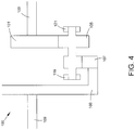
- FIG. 4 provides a schematic view of an epicyclical gear system 100 in accordance with some embodiments of the present disclosure.
- the epicyclical gear system 100 may be a compound star gear system.
- a sun gear 101 is coupled to and driven by a first rotatable shaft 103.
- the sun gear 101 is engaged with one or more planet gears 105, such that rotation of the sun gear 101 causes rotation of the one or more planet gears 105.
- the planet gears 105 may be star gears, such that the planet gears 105 rotate about an axis that is fixed relative to the axis of rotation of the sun gear 101.
- Each of the one or more planet gears 105 are engaged with a ring gear 107.
- the ring gear 107 is coupled via a ring gear hub 108 to a second rotatable shaft 109.
- Rotation of the first rotatable shaft 103 thus drives rotation of the second rotatable shaft 109 via rotation of the sun gear 101, one or more planet gears 105, and ring gear 107.
- the first rotatable shaft 103 may be a turbine shaft (i.e. high or low speed spool) of a turbine engine
- the second rotatable shaft 109 may be a fan shaft or fan rotor.
- FIG. 5 provides a detailed and schematic view of a housing assembly 111 of an epicyclical gear system 100 in accordance with some embodiments of the present disclosure.
- Each of the one or more planet gears 105 may comprise a cylindrical gear shaft 123, a sun gear engaging gear 125, and a ring gear engaging gear 127.
- the sun gear engaging gear 125 and ring gear engaging gear 127 may be carried by the cylindrical gear shaft 123.
- Each of the one or more planet gears 105 is carried by the housing assembly 111.
- the planet gears 105 may be a compound star gear of the epicyclical gear system 100.
- the housing assembly 111 may comprise a forward housing member 113 and an aft housing member 115.
- the housing assembly 111 further comprises an intermediate housing member 114.
- One or more of the housing members 113, 114, 115 may be joined together.
- the forward housing member 113 and aft housing member 115 each define a plurality of gear shaft pockets 116 having a cylindrical wall 120.
- the intermediate housing member 114 may define a plurality of bores 118.
- a cylindrical gear shaft 123 of a planet gear 105 may have a forward end portion 141 disposed within one of the plurality of gear shaft pockets 116 formed by the forward housing member 113.
- the cylindrical gear shaft 123 of the same planet gear 105 may have an aft end portion 142 disposed within one of the plurality of gear shaft pockets 116 formed by the aft housing member 115.
- the cylindrical gear shaft 123 may be disposed within each gear shaft pocket 116 coaxially with the cylindrical wall 120 of the gear shaft pocket 116.
- the cylindrical gear shaft 123 may extend through the bore 118 defined by the intermediate housing member 114.
- the sun gear engaging gear 125 and ring gear engaging gear 127 of planet gear 105 may be carried by the gear shaft 123 between the forward end portion 141 and the aft end portion 142.
- the housing assembly 111 may further comprise a bearing assembly 117.
- the housing assembly 111 may comprise a forward bearing assembly and an aft bearing assembly.
- the bearing assembly 117 may comprise a bearing.
- a forward bearing 119 may be disposed over at least a portion of the forward end portion 141 of the gear shaft 123 and an aft bearing 121 may be disposed over at least a portion of the aft end portion 142 of the gear shaft 123.
- Each of the bearings 119, 121 may rotatably carry the planet gear 105.
- Each of the bearings 119, 121 may be a roller element bearing.
- the constituent pieces of the system 100 as described above and including additional carrier assemblies, housings, and bearings, may move relative to one another. Even small changes in the relative positioning of one component to another can have significant impacts on performance of the system 100. For example, misalignment of enmeshed gear teeth and/or bearings can cause uneven gear and/or bearing loading, and degradation or damage to gear teeth. For example, misalignment of enmeshed gear teeth and/or bearings can cause uneven gear and/or bearing loading, degradation or damage to gear teeth, and reduction of bearing lives and bearing stability.
- each planet gear 105 is carried by the gear shaft 123 partly disposed within gear shaft pockets 116 of a forward housing member 113 and an aft housing member 115, relative movement or changes in relative positioning between the forward housing member 113 and aft housing member 115 can cause misalignment of the planet gear 105.
- relative movement or changes in relative positioning between the intermediate housing member 114 and either or both of the forward housing member 113 and aft housing member 115 can cause misalignment of the planet gear 105.
- This misalignment may in turn lead to uneven load sharing among the planet gears 105, gear degradation, and shortened useful life of the planet gears 105 and/or the planet bearings 119, 121.
- Factors that may contribute to planet gear misalignment include unaligned forces between the forward bearing 119 and aft bearing 121, manufacturing inaccuracies for the positions of the gear shaft pockets 116 and bore 118, ability to reassembly the forward and aft housings in the same position that they were machined, gear tolerance, and inflexibility and/or relative stiffness between each of the housing members 113, 114, 115.
- the present disclosure is therefore directed to systems and methods for improving and maintaining planet gear alignment in an epicyclical gear system. More specifically, the present disclosure is directed to a planet gear housing assembly for an epicyclical gear system having an aft planet carrier assembly, a forward planet carrier assembly, and a plurality of planet gears each carried by the aft and forward planet carrier assemblies. A static curvic joint is provided between the aft planet carrier assembly and the forward planet carrier assembly.
- a planet gear housing assembly 111 may comprise an aft planet carrier assembly 131, a forward planet carrier assembly 162, and a plurality of planet gears 105 each carried by the aft planet carrier assembly 131 and forward carrier planet assembly.
- Figure 6 is an isometric view of a forward planet carrier assembly of a planet gear housing assembly in accordance with some embodiments of the present disclosure.
- Figure 7 is an isometric view of an aft planet carrier assembly of a planet gear housing assembly in accordance with some embodiments of the present disclosure.
- Figure 8 is a partial cross sectional view of a forward planet carrier assembly coupled to an aft planet carrier assembly of a planet gear housing assembly in accordance with some embodiments.
- An aft planet carrier assembly 131 may comprise one or both of the intermediate housing member 114 and the aft housing member 115.
- the aft planet carrier assembly 131 may comprise an aft flange 136.
- the aft flange 136 may be the intermediate housing member 114, the aft housing member 115, or another flange member.
- the aft flange 136 may define a central aperture 132 and a plurality of gear shaft pockets 137 positioned about the circumference of and radially outward of the central aperture 132.
- Each of the gear shaft pockets 116 may have a cylindrical wall 138.
- the aft flange 136 may further comprise a radially outer mounting surface 139 for coupling the aft planet carrier assembly 131 to an engine casing.
- the aft planet carrier assembly 131 may further comprise an annular mounting flange 133.
- the annular mounting flange 133 may be positioned forward of and coaxial with the central aperture 132.
- the annular mounting flange 133 may extend substantially perpendicularly from the aft flange 136.
- the annular mounting flange 133 may form a forward facing mounting surface 134 comprising a curvic structure 135.
- a forward planet carrier assembly 161 may comprise a forward flange 162 and an annular mounting flange 143.
- the forward planet carrier assembly 161 may be the forward housing member 113.
- the forward flange 162 may define a central aperture 144 and a plurality of gear shaft pockets 145 positioned about the circumference and radially outward of the central aperture 144.
- Each gear shaft pocket 145 may have a cylindrical wall 146.
- the annular mounting flange 143 may be positioned aft of and coaxial with the central aperture 144.
- the annular mounting flange 143 may form an aft facing mounting surface 147 comprising a curvic structure 148.
- the annular mounting flange 143 may extend substantially perpendicularly from the forward flange 162.
- a plurality of planet gears 105 may be carried by the forward planet carrier assembly 161 and the aft planet carrier assembly 131.
- Each of the planet gears 105 may comprise a cylindrical shaft 123 having a forward end portion 141 disposed in a gear shaft pocket 145 of the forward flange 162.
- the forward end portion 141 may be disposed in the gear shaft pocket 145 coaxial with the cylindrical wall 146 defining gear shaft pocket 145.
- the cylindrical shaft may have an aft end portion 142 disposed within a gear shaft pocket 137 of the aft flange 136, and may be disposed in the gear shaft pocket 137 coaxial with the cylindrical wall 138.
- Each planet gear 105 may further comprise one or more gears carried by the cylindrical shaft 123 between the forward end portion 141 and the aft end portion 142.
- the gears may be, for example, a sun gear engaging portion 125 of the planet gear 105 and/or a ring gear engaging portion 127 of the planet gear 105.
- the curvic structures 135, 148 of the aft planet carrier assembly 131 and the forward planet carrier assembly 161 may be positioned relative to each other to form a static curvic joint 165.
- Figure 9 provides a partial isometric view of a curvic joint 165.
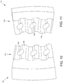
- a portion of the curvic structure 148 of the forward planet carrier assembly 161 is shown isometrically in Figure 10 .
- a portion of the curvic structure 135 of the aft planet carrier assembly 131 is shown isometrically in Figure 11 .
- the curvic structure 148 of the forward planet carrier assembly 161 may comprise a plurality of teeth 152 defined by and extending away from the aft facing mounting surface 147.
- the aft facing mounting surface 147 may further define a plurality of fastener bores 153, with each fastener bore 153 positioned between a pair of adjacent teeth 152.
- the teeth 152 may be shaped and dimensioned to form a curvic joint 165 with the curvic structure 135 of the aft planet carrier assembly 131.
- the curvic structure 135 of the aft planet carrier assembly 131 may comprise a plurality of teeth 151 defined by and extending away from the forward facing mounting surface 134.
- the forward facing mounting surface 134 may further define a plurality of fastener bores 154, with each fastener bore 154 positioned between a pair of adjacent teeth 151.
- the teeth 151 may be shaped and dimensioned to form a curvic joint 165 with the curvic structure 148 of the forward planet carrier assembly 161.
- a fastener 155 may be positioned in each associated set of fastener bores 153, 154 that align when the curvic structures 135, 148 are positioned to form a curvic joint 165.
- the fastener 155 is a bolt and nut.
- a fastener 155 may be provided for each associated pair of fastener bores 153, 154.
- Figure 12 is a flow diagram of a method 1200 of reducing relative movement between static components of an epicyclical gear system in accordance with some embodiments of the present disclosure.
- Method 1200 starts at Block 1201.
- the steps of method 1200, presented at Blocks 1201 through 1217, may be performed in the order presented in Figure 12 or in another order.
- One or more steps of the method 1200 may not be performed.
- a static aft planet carrier assembly 131 may be provided.
- the aft planet carrier assembly 131 may comprise an aft flange 136 defining a central aperture 132 and an annular mounting flange 133 positioned forward of and coaxial with the central aperture 132.
- the annular mounting flange 133 may form a forward facing mounting surface 134 comprising a curvic structure 135.
- the aft flange 136 may further define a plurality of gear shaft pockets 137 positioned about the circumference and radially outward of the central aperture 132, each pocket having a cylindrical wall 138.
- a static forward planet carrier assembly 161 may be provided.
- the forward planet carrier assembly 161 may comprise a forward flange 162 defining a central aperture 144 and an annular mounting flange 143 positioned aft of and coaxial with the central aperture 144.
- the annular mounting flange 143 may form an aft facing mounting surface 147 comprising a curvic structure 148.
- the forward flange 162 may further define a plurality of gear shaft pockets 145 positioned about the circumference and radially outward of the central aperture 144, each pocket having a cylindrical wall 146.
- the aft planet carrier assembly 131 and the forward planet carrier assembly 161 may be coupled.
- the coupling may be achieved by mating the curvic structure 135 of the forward facing mounting surface 134 to the curvic structure 148 of the aft facing mounting surface 147 to thereby form a static curvic joint 165.
- the coupling of the aft planet carrier assembly and the forward planet carrier assembly may form a plurality of axially aligned gear shaft pocket pairs.
- each planet gear 105 of a plurality of planet gears may be positioned in each of the plurality of axially aligned gear shaft pocket pairs.
- Each planet gear 105 may comprise a cylindrical shaft 123 having a forward end portion 141 disposed in a gear shaft pocket 145 of the forward planet carrier assembly 161 coaxially with the cylindrical wall 146 of the pocket 145, and an aft end portion 142 disposed within a gear shaft pocket 137 of the aft planet carrier assembly 131 coaxially with the cylindrical wall 138 of the pocket 137.
- Each planet gear 105 may have one or more gears (e.g. sun gear engaging gear 125 and ring gear engaging gear 127) carried by the shaft 123 between the forward and aft end portions 141, 142.
- a bearing 119, 121 may be positioned at least partly in a gear shaft pocket 137, 145.
- a portion of a cylindrical shaft 123 of a planet gear 105 may be carried with the bearing 119, 121.
- each planet gear 105 may be rotated while maintaining the curvic joint 165 static.
- the rotation may be driven by a sun gear 101 of a compound star gear assembly.
- Method 1200 ends at Block 1217.
- the presently disclosed systems and methods provide numerous advantages over prior art systems.
- a static (i.e. not rotating) curvic joint to join a forward and aft planet carrier assembly
- the disclosed planet gear housing assembly reduces fore-to-aft misalignment of planet gear shafts caused by relative movement between the forward and aft planet carrier assemblies.
- the aft planet carrier assembly may be rigidly mounted to the engine casing.
- the forward planet carrier assembly may be held to the aft planet carrier assembly with less relative movement between the two than in a standard coupling. Less relative movement is advantageous during assembly as well as operation of the epicyclical gear system.
- the disclosed static curvic joint is additionally advantageous during assembly of the epicyclical gear system.
- One contributor to fore-to-aft misalignment of the gear shaft of each planet gear may be the difficultly in reassembling the housings with the same alignment, orientation, and position with which they were machined. While machining accuracy can be improved by machining the housings together (e.g. line bored), the static curvic joint improves fore-to-aft alignment by reacting torque during the reassembly process and thus ensures close precision of bore alignment through manufacturing, machining, and assembly of the epicyclical gear system.
- the subject-matter of the disclosure may also relate, among others, to the following aspects:
Landscapes
- Engineering & Computer Science (AREA)
- General Engineering & Computer Science (AREA)
- Mechanical Engineering (AREA)
- Chemical & Material Sciences (AREA)
- Combustion & Propulsion (AREA)
- Retarders (AREA)
- Structures Of Non-Positive Displacement Pumps (AREA)
Abstract
Description
- The present disclosure relates to epicyclic gear systems for gas turbine engines, more particularly to a planet gear housing assembly for an epicyclical gear assembly.
- Epicyclical gear systems may be used in rotating machinery to transfer energy from one component, such as a rotatable shaft, to another. By altering certain variables such as the number, size, and teeth of the gears, an epicyclical gear system may be designed to transfer energy between components at a desired ratio and often convert a high-speed, low-torque input to a lower-speed, higher-torque output.
- Epicyclical gear systems may be suitable for a wide range of applications, including the transfer of energy from a turbine shaft to a fan rotor in a geared turbofan engine. However, in such dynamic applications the epicyclical gear system must be designed to allow some degree of relative movement between parts of the system to avoid excessive wear and, in extreme conditions, system failure.
- The present disclosure provides a planet gear housing assembly for an epicyclical gear assembly, and a gas turbine engines, as set out in the appended claims.
- According to a first aspect the present disclosure provides a planet gear housing assembly for an epicyclical gear assembly comprises an aft planet carrier assembly, a forward planet carrier assembly, and a plurality of planet gears. The aft planet carrier assembly comprises an aft flange and an annular mounting flange. The aft flange defines a central aperture and a plurality of gear shaft pockets positioned about the circumference and radially outward of the central aperture, each pocket having a cylindrical wall. The annular mounting flange is positioned forward of and coaxial with the central aperture and forms a forward facing mounting surface comprising a curvic structure. The forward planet carrier assembly comprises a forward flange and an annular mounting flange. The forward flange defines a central aperture and a plurality of gear shaft pockets positioned about the circumference and radially outward of the central aperture, each pocket having a cylindrical wall. The annular mounting flange is positioned aft of and coaxial with the central aperture and forms an aft facing mounting surface comprising a curvic structure. The plurality of planet gears each comprise a cylindrical shaft having a forward end portion disposed in a gear shaft pocket of the forward planet carrier assembly coaxially with the cylindrical wall of the pocket, an aft end portion disposed within a gear shaft pocket of the aft planet carrier assembly coaxially with the cylindrical wall of the pocket, and one or more gears carried by the shaft between the forward and aft end portions. The curvic structures of the mounting surfaces are positioned relative to each other to thereby form a static curvic joint.
- In some embodiments the annular mounting flange of the aft planet carrier assembly extends from the aft flange. In some embodiments the annular mounting flange of the forward planet carrier assembly extends from the forward flange. In some embodiments one or both of the annular mounting flange of the aft planet carrier assembly and the annular mounting flange of the forward planet carrier assembly extends substantially perpendicularly from a respective one of the aft flange and the forward flange.
- In some embodiments the aft flange comprises a radially outer mounting surface for mounting the planet gear housing assembly to an engine casing. In some embodiments the curvic structure of the aft facing mounting surface comprises a plurality of teeth extending away from the aft facing mounting surface. In some embodiments the aft facing mounting surface defines a plurality of fastener bores, with each fastener bore of the plurality of fastener bores positioned between adjacent teeth of the plurality of teeth. In some embodiments the curvic structure of the forward facing mounting surface comprises a plurality of teeth extending away from the forward facing mounting surface. In some embodiments the forward facing mounting surface defines a plurality of fastener bores, with each fastener bore of the plurality of fastener bores positioned between adjacent teeth of the plurality of teeth. In some embodiments the static curvic joint comprises the plurality of teeth extending away from the aft facing mounting surface enmeshed with the plurality of teeth extending away from the forward facing mounting surface. In some embodiments the static curvic joint further comprises a plurality of fasteners, with each fastener of the plurality of fasteners positioned through an aligned pair of fastener bores.
- According to second aspect the present disclosure provides a gas turbine engine for an aircraft comprises an engine core, a fan, and a gearbox. The engine core comprises a turbine, a compressor, and a core shaft connecting the turbine to the compressor. The fan is located upstream of the engine core and comprises a plurality of fan blades. The gearbox receives an input from the core shaft and outputs drive to the fan so as to drive the fan at a lower rotational speed than the core shaft. The gearbox has a planet gear housing assembly of the first aspect.
- In some embodiments each of the plurality of planet gears comprise a sun gear engaging gear and a ring gear engaging gear carried by the shaft between the forward and aft end portions. In some embodiments the shaft and gears form a compound star gear in an epicyclical gear system. In some embodiments the gearbox further comprises a roller element bearing disposed over at least a portion of one or both of the forward end portion and the aft end portion of the gear shaft. In some embodiments the curvic structure of the aft facing mounting surface and the forward facing mounting surface each comprise a plurality of teeth extending away from the respective one of the aft facing mounting surface and the forward facing mounting surface.
- According to a third aspect of the present disclosure provides a method is disclosed for reducing relative movement between static components of an epicyclical gear system. The method comprises providing a static aft planet carrier assembly, providing a static forward planet carrier assembly, and coupling the aft planet carrier assembly and forward planet carrier assembly. The static aft planet carrier assembly comprises an aft flange defining a central aperture and an annular mounting flange positioned forward of and coaxial with the central aperture. The mounting flange forms a forward facing mounting surface comprising a curvic structure. The static forward planet carrier assembly comprises a forward flange defining a central aperture and an annular mounting flange positioned aft of and coaxial with the central aperture. The mounting flange forms an aft facing mounting surface comprising a curvic structure. The aft planet carrier assembly and the forward planet carrier assembly are coupled by mating the curvic structure of the forward facing mounting surface to the curvic structure of the aft facing mounting surface to thereby form a static curvic joint.
- In some embodiments the aft flange further defines a plurality of gear shaft pockets positioned about the circumference and radially outward of the central aperture, each pocket having a cylindrical wall. In some embodiments the forward flange further defines a plurality of gear shaft pockets positioned about the circumference and radially outward of the central aperture, each pocket having a cylindrical wall. In some embodiments the coupling of the aft planet carrier assembly and the forward planet carrier assembly forms a plurality of axially aligned gear shaft pocket pairs.
- In some embodiments the method of further comprises positioning one planet gear of a plurality of planet gears in each of the plurality of axially aligned gear shaft pocket pairs, each planet gear comprising a cylindrical shaft having a forward end portion disposed in a gear shaft pocket of the forward planet carrier assembly coaxially with the cylindrical wall of the pocket, an aft end portion disposed within a gear shaft pocket of the aft planet carrier assembly coaxially with the cylindrical wall of the pocket, and one or more gears carried by the shaft between the forward and aft end portions. In some embodiments the method of further comprises positioning a bearing at least partly in a gear shaft pocket and carrying a portion of a cylindrical shaft of a planet gear with the bearing. In some embodiments the method of further comprises rotating the cylindrical shaft of each planet gear while maintaining the curvic joint static. In some embodiments the rotation is driven by a sun gear of a compound star gear assembly.
- The skilled person will appreciate that except where mutually exclusive, a feature or parameter described in relation to any one of the above aspects may be applied to any other aspect. Furthermore, except where mutually exclusive, any feature or parameter described herein may be applied to any aspect and/or combined with any other feature or parameter described herein.
- The following will be apparent from elements of the figures, which are provided for illustrative purposes.
-
Fig. 1 is a sectional side view of a gas turbine engine. -
Fig. 2 is a close up sectional side view of an upstream portion of a gas turbine engine. -
Fig. 3 is a partially cut-away view of a gearbox for a gas turbine engine. -
Fig. 4 is a schematic and cross sectional view of an epicyclical gear system in accordance with some embodiments of the present disclosure. -
Fig. 5 is a detailed schematic and cross sectional view of a planet gear disposed in an epicyclical gear system in accordance with some embodiments of the present disclosure. -
Fig. 6 is an isometric view of a forward planet carrier assembly of a planet gear housing assembly in accordance with some embodiments of the present disclosure. -
Fig. 7 is an isometric view of an aft planet carrier assembly of a planet gear housing assembly in accordance with some embodiments of the present disclosure. -
Fig. 8 is a partial cross sectional view of a forward planet carrier assembly coupled to an aft planet carrier assembly of a planet gear housing assembly in accordance with some embodiments. -
Fig. 9 is a partial isometric view of a forward planet carrier assembly coupled to an aft planet carrier assembly of a planet gear housing assembly in accordance with some embodiments. -
Fig. 10 is a partial isometric view of a curvic structure of a forward planet carrier assembly of a planet gear housing assembly in accordance with some embodiments. -
Fig. 11 is a partial isometric view of a curvic structure of an aft planet carrier assembly of a planet gear housing assembly in accordance with some embodiments. -
Fig. 12 is a flow diagram of a method in accordance with some embodiments of the present disclosure. - The present application discloses illustrative (i.e., example) embodiments. The claimed inventions are not limited to the illustrative embodiments.
- For the purposes of promoting an understanding of the principles of the disclosure, reference will now be made to a number of illustrative embodiments in the drawings and specific language will be used to describe the same.
- As noted elsewhere herein, the present disclosure may relate to a gas turbine engine. Such a gas turbine engine may comprise an engine core comprising a turbine, a combustor, a compressor, and a core shaft connecting the turbine to the compressor. Such a gas turbine engine may comprise a fan (having fan blades) located upstream of the engine core.
- Arrangements of the present disclosure may be particularly, although not exclusively, beneficial for fans that are driven via a gearbox. Accordingly, the gas turbine engine may comprise a gearbox that receives an input from the core shaft and outputs drive to the fan so as to drive the fan at a lower rotational speed than the core shaft. The input to the gearbox may be directly from the core shaft, or indirectly from the core shaft, for example via a spur shaft and/or gear. The core shaft may rigidly connect the turbine and the compressor, such that the turbine and compressor rotate at the same speed (with the fan rotating at a lower speed).
- The gas turbine engine as described and/or claimed herein may have any suitable general architecture. For example, the gas turbine engine may have any desired number of shafts that connect turbines and compressors, for example one, two or three shafts. Purely by way of example, the turbine connected to the core shaft may be a first turbine, the compressor connected to the core shaft may be a first compressor, and the core shaft may be a first core shaft. The engine core may further comprise a second turbine, a second compressor, and a second core shaft connecting the second turbine to the second compressor. The second turbine, second compressor, and second core shaft may be arranged to rotate at a higher rotational speed than the first core shaft.
- In such an arrangement, the second compressor may be positioned axially downstream of the first compressor. The second compressor may be arranged to receive (for example directly receive, for example via a generally annular duct) flow from the first compressor.
- The gearbox may be arranged to be driven by the core shaft that is configured to rotate (for example in use) at the lowest rotational speed (for example the first core shaft in the example above). For example, the gearbox may be arranged to be driven only by the core shaft that is configured to rotate (for example in use) at the lowest rotational speed (for example only be the first core shaft, and not the second core shaft, in the example above). Alternatively, the gearbox may be arranged to be driven by any one or more shafts, for example the first and/or second shafts in the example above.
- The gearbox may be a reduction gearbox (in that the output to the fan is a lower rotational rate than the input from the core shaft). Any type of gearbox may be used. For example, the gearbox may be a "planetary" or "star" gearbox, as described in more detail elsewhere herein. The gearbox may have any desired reduction ratio (defined as the rotational speed of the input shaft divided by the rotational speed of the output shaft), for example greater than 2.5, for example in the range of from 3 to 4.2, or 3.2 to 3.8, for example on the order of or at least 3, 3.1, 3.2, 3.3, 3.4, 3.5, 3.6, 3.7, 3.8, 3.9, 4, 4.1 or 4.2. The gear ratio may be, for example, between any two of the values in the previous sentence. Purely by way of example, the gearbox may be a "star" gearbox having a ratio in the range of from 3.1 or 3.2 to 3.8. In some arrangements, the gear ratio may be outside these ranges.
- In any gas turbine engine as described and/or claimed herein, a combustor may be provided axially downstream of the fan and compressor(s). For example, the combustor may be directly downstream of (for example at the exit of) the second compressor, where a second compressor is provided. By way of further example, the flow at the exit to the combustor may be provided to the inlet of the second turbine, where a second turbine is provided. The combustor may be provided upstream of the turbine(s).
- The or each compressor (for example the first compressor and second compressor as described above) may comprise any number of stages, for example multiple stages. Each stage may comprise a row of rotor blades and a row of stator vanes, which may be variable stator vanes (in that their angle of incidence may be variable). The row of rotor blades and the row of stator vanes may be axially offset from each other.
- The or each turbine (for example the first turbine and second turbine as described above) may comprise any number of stages, for example multiple stages. Each stage may comprise a row of rotor blades and a row of stator vanes. The row of rotor blades and the row of stator vanes may be axially offset from each other.
- Each fan blade may be defined as having a radial span extending from a root (or hub) at a radially inner gas-washed location, or 0% span position, to a tip at a 100% span position. The ratio of the radius of the fan blade at the hub to the radius of the fan blade at the tip may be less than (or on the order of) any of: 0.4, 0.39, 0.38 0.37, 0.36, 0.35, 0.34, 0.33, 0.32, 0.31, 0.3, 0.29, 0.28, 0.27, 0.26, or 0.25. The ratio of the radius of the fan blade at the hub to the radius of the fan blade at the tip may be in an inclusive range bounded by any two of the values in the previous sentence (i.e. the values may form upper or lower bounds), for example in the range of from 0.28 to 0.32. These ratios may commonly be referred to as the hub-to-tip ratio. The radius at the hub and the radius at the tip may both be measured at the leading edge (or axially forwardmost) part of the blade. The hub-to-tip ratio refers, of course, to the gas-washed portion of the fan blade, i.e. the portion radially outside any platform.
- The radius of the fan may be measured between the engine centreline and the tip of a fan blade at its leading edge. The fan diameter (which may simply be twice the radius of the fan) may be greater than (or on the order of) any of: 220 cm, 230 cm, 240 cm, 250 cm (around 100 inches), 260 cm, 270 cm (around 105 inches), 280 cm (around 110 inches), 290 cm (around 115 inches), 300 cm (around 120 inches), 310 cm, 320 cm (around 125 inches), 330 cm (around 130 inches), 340 cm (around 135 inches), 350cm, 360cm (around 140 inches), 370 cm (around 145 inches), 380 (around 150 inches) cm, 390 cm (around 155 inches), 400 cm, 410 cm (around 160 inches) or 420 cm (around 165 inches). The fan diameter may be in an inclusive range bounded by any two of the values in the previous sentence (i.e. the values may form upper or lower bounds), for example in the range of from 240 cm to 280 cm or 330 cm to 380 cm.
- The rotational speed of the fan may vary in use. Generally, the rotational speed is lower for fans with a higher diameter. Purely by way of non-limitative example, the rotational speed of the fan at cruise conditions may be less than 2500 rpm, for example less than 2300 rpm. Purely by way of further non-limitative example, the rotational speed of the fan at cruise conditions for an engine having a fan diameter in the range of from 220 cm to 300 cm (for example 240 cm to 280 cm or 250 cm to 270cm) may be in the range of from 1700 rpm to 2500 rpm, for example in the range of from 1800 rpm to 2300 rpm, for example in the range of from 1900 rpm to 2100 rpm. Purely by way of further non-limitative example, the rotational speed of the fan at cruise conditions for an engine having a fan diameter in the range of from 330 cm to 380 cm may be in the range of from 1200 rpm to 2000 rpm, for example in the range of from 1300 rpm to 1800 rpm, for example in the range of from 1400 rpm to 1800 rpm.
- In use of the gas turbine engine, the fan (with associated fan blades) rotates about a rotational axis. This rotation results in the tip of the fan blade moving with a velocity Utip. The work done by the fan blades 13 on the flow results in an enthalpy rise dH of the flow. A fan tip loading may be defined as dH/Utip2, where dH is the enthalpy rise (for example the 1-D average enthalpy rise) across the fan and Utip is the (translational) velocity of the fan tip, for example at the leading edge of the tip (which may be defined as fan tip radius at leading edge multiplied by angular speed). The fan tip loading at cruise conditions may be greater than (or on the order of) any of: 0.28, 0.29, 0.30, 0.31, 0.32, 0.33, 0.34, 0.35, 0.36, 0.37, 0.38, 0.39 or 0.4 (all units in this paragraph being Jkg-1K-1/(ms-1)2). The fan tip loading may be in an inclusive range bounded by any two of the values in the previous sentence (i.e. the values may form upper or lower bounds), for example in the range of from 0.28 to 0.31, or 0.29 to 0.3.
- Gas turbine engines in accordance with the present disclosure may have any desired bypass ratio, where the bypass ratio is defined as the ratio of the mass flow rate of the flow through the bypass duct to the mass flow rate of the flow through the core at cruise conditions. In some arrangements the bypass ratio may be greater than (or on the order of) any of the following: 10, 10.5, 11, 11.5, 12, 12.5, 13, 13.5, 14, 14.5, 15, 15.5, 16, 16.5, 17, 17.5, 18, 18.5, 19, 19.5 or 20. The bypass ratio may be in an inclusive range bounded by any two of the values in the previous sentence (i.e. the values may form upper or lower bounds), for example in the range of
form 12 to 16, 13 to 15, or 13 to 14. The bypass duct may be substantially annular. The bypass duct may be radially outside the core engine. The radially outer surface of the bypass duct may be defined by a nacelle and/or a fan case. - The overall pressure ratio of a gas turbine engine as described and/or claimed herein may be defined as the ratio of the stagnation pressure upstream of the fan to the stagnation pressure at the exit of the highest pressure compressor (before entry into the combustor). By way of non-limitative example, the overall pressure ratio of a gas turbine engine as described and/or claimed herein at cruise may be greater than (or on the order of) any of the following: 35, 40, 45, 50, 55, 60, 65, 70, 75. The overall pressure ratio may be in an inclusive range bounded by any two of the values in the previous sentence (i.e. the values may form upper or lower bounds), for example in the range of from 50 to 70.
- Specific thrust of an engine may be defined as the net thrust of the engine divided by the total mass flow through the engine. At cruise conditions, the specific thrust of an engine described and/or claimed herein may be less than (or on the order of) any of the following: 110 Nkg-1s, 105 Nkg-1s, 100 Nkg-1s, 95 Nkg-1s, 90 Nkg-1s, 85 Nkg-1s or 80 Nkg-1s. The specific thrust may be in an inclusive range bounded by any two of the values in the previous sentence (i.e. the values may form upper or lower bounds), for example in the range of from 80 Nkg-1s to 100 Nkg-1s, or 85 Nkg-1s to 95 Nkg-1s. Such engines may be particularly efficient in comparison with conventional gas turbine engines.
- A gas turbine engine as described and/or claimed herein may have any desired maximum thrust. Purely by way of non-limitative example, a gas turbine as described and/or claimed herein may be capable of producing a maximum thrust of at least (or on the order of) any of the following: 160kN, 170kN, 180kN, 190kN, 200kN, 250kN, 300kN, 350kN, 400kN, 450kN, 500kN, or 550kN. The maximum thrust may be in an inclusive range bounded by any two of the values in the previous sentence (i.e. the values may form upper or lower bounds). Purely by way of example, a gas turbine as described and/or claimed herein may be capable of producing a maximum thrust in the range of from 330kN to 420 kN, for example 350kN to 400kN. The thrust referred to above may be the maximum net thrust at standard atmospheric conditions at sea level plus 15 degrees C (ambient pressure 101.3kPa,
temperature 30 degrees C), with the engine static. - In use, the temperature of the flow at the entry to the high pressure turbine may be particularly high. This temperature, which may be referred to as TET, may be measured at the exit to the combustor, for example immediately upstream of the first turbine vane, which itself may be referred to as a nozzle guide vane. At cruise, the TET may be at least (or on the order of) any of the following: 1400K, 1450K, 1500K, 1550K, 1600K or 1650K. The TET at cruise may be in an inclusive range bounded by any two of the values in the previous sentence (i.e. the values may form upper or lower bounds). The maximum TET in use of the engine may be, for example, at least (or on the order of) any of the following: 1700K, 1750K, 1800K, 1850K, 1900K, 1950K or 2000K. The maximum TET may be in an inclusive range bounded by any two of the values in the previous sentence (i.e. the values may form upper or lower bounds), for example in the range of from 1800K to 1950K. The maximum TET may occur, for example, at a high thrust condition, for example at a maximum take-off (MTO) condition.
- A fan blade and/or aerofoil portion of a fan blade described and/or claimed herein may be manufactured from any suitable material or combination of materials. For example at least a part of the fan blade and/or aerofoil may be manufactured at least in part from a composite, for example a metal matrix composite and/or an organic matrix composite, such as carbon fibre. By way of further example at least a part of the fan blade and/or aerofoil may be manufactured at least in part from a metal, such as a titanium based metal or an aluminium based material (such as an aluminium-lithium alloy) or a steel based material. The fan blade may comprise at least two regions manufactured using different materials. For example, the fan blade may have a protective leading edge, which may be manufactured using a material that is better able to resist impact (for example from birds, ice or other material) than the rest of the blade. Such a leading edge may, for example, be manufactured using titanium or a titanium-based alloy. Thus, purely by way of example, the fan blade may have a carbon-fibre or aluminium based body (such as an aluminium lithium alloy) with a titanium leading edge.
- A fan as described and/or claimed herein may comprise a central portion, from which the fan blades may extend, for example in a radial direction. The fan blades may be attached to the central portion in any desired manner. For example, each fan blade may comprise a fixture which may engage a corresponding slot in the hub (or disc). Purely by way of example, such a fixture may be in the form of a dovetail that may slot into and/or engage a corresponding slot in the hub/disc in order to fix the fan blade to the hub/disc. By way of further example, the fan blades maybe formed integrally with a central portion. Such an arrangement may be referred to as a bladed disc or a bladed ring. Any suitable method may be used to manufacture such a bladed disc or bladed ring. For example, at least a part of the fan blades may be machined from a block and/or at least part of the fan blades may be attached to the hub/disc by welding, such as linear friction welding.
- The gas turbine engines described and/or claimed herein may or may not be provided with a variable area nozzle (VAN). Such a variable area nozzle may allow the exit area of the bypass duct to be varied in use. The general principles of the present disclosure may apply to engines with or without a VAN.
- The fan of a gas turbine as described and/or claimed herein may have any desired number of fan blades, for example 14, 16, 18, 20, 22, 24 or 26 fan blades.
- As used herein, cruise conditions have the conventional meaning and would be readily understood by the skilled person. Thus, for a given gas turbine engine for an aircraft, the skilled person would immediately recognise cruise conditions to mean the operating point of the engine at mid-cruise of a given mission (which may be referred to in the industry as the "economic mission") of an aircraft to which the gas turbine engine is designed to be attached. In this regard, mid-cruise is the point in an aircraft flight cycle at which 50% of the total fuel that is burned between top of climb and start of descent has been burned (which may be approximated by the midpoint - in terms of time and/or distance- between top of climb and start of descent. Cruise conditions thus define an operating point of the gas turbine engine that provides a thrust that would ensure steady state operation (i.e. maintaining a constant altitude and constant Mach Number) at mid-cruise of an aircraft to which it is designed to be attached, taking into account the number of engines provided to that aircraft. For example where an engine is designed to be attached to an aircraft that has two engines of the same type, at cruise conditions the engine provides half of the total thrust that would be required for steady state operation of that aircraft at mid-cruise.
- In other words, for a given gas turbine engine for an aircraft, cruise conditions are defined as the operating point of the engine that provides a specified thrust (required to provide - in combination with any other engines on the aircraft - steady state operation of the aircraft to which it is designed to be attached at a given mid-cruise Mach Number) at the mid-cruise atmospheric conditions (defined by the International Standard Atmosphere according to ISO 2533 at the mid-cruise altitude). For any given gas turbine engine for an aircraft, the mid-cruise thrust, atmospheric conditions and Mach Number are known, and thus the operating point of the engine at cruise conditions is clearly defined.
- Purely by way of example, the forward speed at the cruise condition may be any point in the range of from Mach 0.7 to 0.9, for example 0.75 to 0.85, for example 0.76 to 0.84, for example 0.77 to 0.83, for example 0.78 to 0.82, for example 0.79 to 0.81, for example on the order of Mach 0.8, on the order of Mach 0.85 or in the range of from 0.8 to 0.85. Any single speed within these ranges may be part of the cruise condition. For some aircraft, the cruise conditions may be outside these ranges, for example below Mach 0.7 or above Mach 0.9.
- Purely by way of example, the cruise conditions may correspond to standard atmospheric conditions (according to the International Standard Atmosphere, ISA) at an altitude that is in the range of from 10000m to 15000m, for example in the range of from 10000m to 12000m, for example in the range of from 10400m to 11600m (around 38000 ft), for example in the range of from 10500m to 11500m, for example in the range of from 10600m to 11400m, for example in the range of from 10700m (around 35000 ft) to 11300m, for example in the range of from 10800m to 11200m, for example in the range of from 10900m to 11100m, for example on the order of 11000m. The cruise conditions may correspond to standard atmospheric conditions at any given altitude in these ranges.
- Purely by way of example, the cruise conditions may correspond to an operating point of the engine that provides a known required thrust level (for example a value in the range of from 30kN to 35kN) at a forward Mach number of 0.8 and standard atmospheric conditions (according to the International Standard Atmosphere) at an altitude of 38000ft (11582m). Purely by way of further example, the cruise conditions may correspond to an operating point of the engine that provides a known required thrust level (for example a value in the range of from 50kN to 65kN) at a forward Mach number of 0.85 and standard atmospheric conditions (according to the International Standard Atmosphere) at an altitude of 35000ft (10668m).
- In use, a gas turbine engine described and/or claimed herein may operate at the cruise conditions defined elsewhere herein. Such cruise conditions may be determined by the cruise conditions (for example the mid-cruise conditions) of an aircraft to which at least one (for example 2 or 4) gas turbine engine may be mounted in order to provide propulsive thrust.
- According to an aspect, there is provided an aircraft comprising a gas turbine engine as described and/or claimed herein. The aircraft according to this aspect is the aircraft for which the gas turbine engine has been designed to be attached. Accordingly, the cruise conditions according to this aspect correspond to the mid-cruise of the aircraft, as defined elsewhere herein.
- According to an aspect, there is provided a method of operating a gas turbine engine as described and/or claimed herein. The operation may be at the cruise conditions as defined elsewhere herein (for example in terms of the thrust, atmospheric conditions and Mach Number).
- According to an aspect, there is provided a method of operating an aircraft comprising a gas turbine engine as described and/or claimed herein. The operation according to this aspect may include (or may be) operation at the mid-cruise of the aircraft, as defined elsewhere herein.
-
Figure 1 illustrates agas turbine engine 10 having a principalrotational axis 9. Theengine 10 comprises anair intake 12 and apropulsive fan 23 that generates two airflows: a core airflow A and a bypass airflow B. Thegas turbine engine 10 comprises a core 11 that receives the core airflow A. Theengine core 11 comprises, in axial flow series, alow pressure compressor 14, a high-pressure compressor 15,combustion equipment 16, a high-pressure turbine 17, alow pressure turbine 19 and acore exhaust nozzle 20. Anacelle 21 surrounds thegas turbine engine 10 and defines a bypass duct 22 and abypass exhaust nozzle 18. The bypass airflow B flows through the bypass duct 22. Thefan 23 is attached to and driven by thelow pressure turbine 19 via ashaft 26 and anepicyclic gearbox 30. - In use, the core airflow A is accelerated and compressed by the
low pressure compressor 14 and directed into thehigh pressure compressor 15 where further compression takes place. The compressed air exhausted from thehigh pressure compressor 15 is directed into thecombustion equipment 16 where it is mixed with fuel and the mixture is combusted. The resultant hot combustion products then expand through, and thereby drive, the high pressure andlow pressure turbines nozzle 20 to provide some propulsive thrust. Thehigh pressure turbine 17 drives thehigh pressure compressor 15 by a suitable interconnectingshaft 27. Thefan 23 generally provides the majority of the propulsive thrust. Theepicyclic gearbox 30 is a reduction gearbox. - An exemplary arrangement for a geared fan
gas turbine engine 10 is shown inFigure 2 . The low pressure turbine 19 (seeFigure 1 ) drives theshaft 26, which is coupled to a sun wheel, or sun gear, 28 of theepicyclic gear arrangement 30. Radially outwardly of thesun gear 28 and intermeshing therewith is a plurality of planet gears 32 that are coupled together by aplanet carrier 34. Theplanet carrier 34 constrains the planet gears 32 to precess around thesun gear 28 in synchronicity whilst enabling eachplanet gear 32 to rotate about its own axis. Theplanet carrier 34 is coupled vialinkages 36 to thefan 23 in order to drive its rotation about theengine axis 9. Radially outwardly of the planet gears 32 and intermeshing therewith is an annulus orring gear 38 that is coupled, vialinkages 40, to a stationary supportingstructure 24. - Note that the terms "low pressure turbine" and "low pressure compressor" as used herein may be taken to mean the lowest pressure turbine stages and lowest pressure compressor stages (i.e. not including the fan 23) respectively and/or the turbine and compressor stages that are connected together by the interconnecting
shaft 26 with the lowest rotational speed in the engine (i.e. not including the gearbox output shaft that drives the fan 23). In some literature, the "low pressure turbine" and "low pressure compressor" referred to herein may alternatively be known as the "intermediate pressure turbine" and "intermediate pressure compressor". Where such alternative nomenclature is used, thefan 23 may be referred to as a first, or lowest pressure, compression stage. - The
epicyclic gearbox 30 is shown by way of example in greater detail inFigure 3 . Each of thesun gear 28, planet gears 32 andring gear 38 comprise teeth about their periphery to intermesh with the other gears. However, for clarity only exemplary portions of the teeth are illustrated inFigure 3 . There are fourplanet gears 32 illustrated, although it will be apparent to the skilled reader that more or fewer planet gears 32 may be provided within the scope of the claimed invention. Practical applications of a planetaryepicyclic gearbox 30 generally comprise at least three planet gears 32. - The
epicyclic gearbox 30 illustrated by way of example inFigures 2 and3 is of the planetary type, in that theplanet carrier 34 is coupled to an output shaft vialinkages 36, with thering gear 38 fixed. However, any other suitable type ofepicyclic gearbox 30 may be used. By way of further example, theepicyclic gearbox 30 may be a star arrangement, in which theplanet carrier 34 is held fixed, with the ring (or annulus)gear 38 allowed to rotate. In such an arrangement thefan 23 is driven by thering gear 38. By way of further alternative example, thegearbox 30 may be a differential gearbox in which thering gear 38 and theplanet carrier 34 are both allowed to rotate. - It will be appreciated that the arrangement shown in
Figures 2 and3 is by way of example only, and various alternatives are within the scope of the present disclosure. Purely by way of example, any suitable arrangement may be used for locating thegearbox 30 in theengine 10 and/or for connecting thegearbox 30 to theengine 10. By way of further example, the connections (such as thelinkages Figure 2 example) between thegearbox 30 and other parts of the engine 10 (such as theinput shaft 26, the output shaft and the fixed structure 24) may have any desired degree of stiffness or flexibility. By way of further example, any suitable arrangement of the bearings between rotating and stationary parts of the engine (for example between the input and output shafts from the gearbox and the fixed structures, such as the gearbox casing) may be used, and the disclosure is not limited to the exemplary arrangement ofFigure 2 . For example, where thegearbox 30 has a star arrangement (described above), the skilled person would readily understand that the arrangement of output and support linkages and bearing locations would typically be different to that shown by way of example inFigure 2 . - Accordingly, the present disclosure extends to a gas turbine engine having any arrangement of gearbox styles (for example star or planetary), support structures, input and output shaft arrangement, and bearing locations.
- Optionally, the gearbox may drive additional and/or alternative components (e.g. the intermediate pressure compressor and/or a booster compressor).
- Other gas turbine engines to which the present disclosure may be applied may have alternative configurations. For example, such engines may have an alternative number of compressors and/or turbines and/or an alternative number of interconnecting shafts. By way of further example, the gas turbine engine shown in
Figure 1 has asplit flow nozzle own nozzle 18 that is separate to and radially outside thecore engine nozzle 20. However, this is not limiting, and any aspect of the present disclosure may also apply to engines in which the flow through the bypass duct 22 and the flow through the core 11 are mixed, or combined, before (or upstream of) a single nozzle, which may be referred to as a mixed flow nozzle. One or both nozzles (whether mixed or split flow) may have a fixed or variable area. - The geometry of the
gas turbine engine 10, and components thereof, is defined by a conventional axis system, comprising an axial direction (which is aligned with the rotational axis 9), a radial direction (in the bottom-to-top direction inFigure 1 ), and a circumferential direction (perpendicular to the page in theFigure 1 view). The axial, radial and circumferential directions are mutually perpendicular. -
Figure 4 provides a schematic view of anepicyclical gear system 100 in accordance with some embodiments of the present disclosure. Theepicyclical gear system 100 may be a compound star gear system. Asun gear 101 is coupled to and driven by a firstrotatable shaft 103. Thesun gear 101 is engaged with one or more planet gears 105, such that rotation of thesun gear 101 causes rotation of the one or more planet gears 105. The planet gears 105 may be star gears, such that the planet gears 105 rotate about an axis that is fixed relative to the axis of rotation of thesun gear 101. - Each of the one or more planet gears 105 are engaged with a
ring gear 107. Thering gear 107 is coupled via aring gear hub 108 to a secondrotatable shaft 109. Rotation of the firstrotatable shaft 103 thus drives rotation of the secondrotatable shaft 109 via rotation of thesun gear 101, one or more planet gears 105, andring gear 107. In some embodiments, the firstrotatable shaft 103 may be a turbine shaft (i.e. high or low speed spool) of a turbine engine, and the secondrotatable shaft 109 may be a fan shaft or fan rotor. -
Figure 5 provides a detailed and schematic view of ahousing assembly 111 of anepicyclical gear system 100 in accordance with some embodiments of the present disclosure. Each of the one or more planet gears 105 may comprise acylindrical gear shaft 123, a sungear engaging gear 125, and a ringgear engaging gear 127. The sungear engaging gear 125 and ringgear engaging gear 127 may be carried by thecylindrical gear shaft 123. Each of the one or more planet gears 105 is carried by thehousing assembly 111. The planet gears 105 may be a compound star gear of theepicyclical gear system 100. - The
housing assembly 111 may comprise aforward housing member 113 and anaft housing member 115. In some embodiments, thehousing assembly 111 further comprises anintermediate housing member 114. One or more of thehousing members forward housing member 113 andaft housing member 115 each define a plurality of gear shaft pockets 116 having acylindrical wall 120. Theintermediate housing member 114 may define a plurality ofbores 118. - A
cylindrical gear shaft 123 of aplanet gear 105 may have aforward end portion 141 disposed within one of the plurality of gear shaft pockets 116 formed by theforward housing member 113. Thecylindrical gear shaft 123 of thesame planet gear 105 may have anaft end portion 142 disposed within one of the plurality of gear shaft pockets 116 formed by theaft housing member 115. Thecylindrical gear shaft 123 may be disposed within eachgear shaft pocket 116 coaxially with thecylindrical wall 120 of thegear shaft pocket 116. Thecylindrical gear shaft 123 may extend through thebore 118 defined by theintermediate housing member 114. The sungear engaging gear 125 and ringgear engaging gear 127 ofplanet gear 105 may be carried by thegear shaft 123 between theforward end portion 141 and theaft end portion 142. - The
housing assembly 111 may further comprise abearing assembly 117. Thehousing assembly 111 may comprise a forward bearing assembly and an aft bearing assembly. The bearingassembly 117 may comprise a bearing. For example, a forward bearing 119 may be disposed over at least a portion of theforward end portion 141 of thegear shaft 123 and anaft bearing 121 may be disposed over at least a portion of theaft end portion 142 of thegear shaft 123. Each of thebearings planet gear 105. Each of thebearings - During operation of the
epicyclical gear system 100 the constituent pieces of thesystem 100 as described above and including additional carrier assemblies, housings, and bearings, may move relative to one another. Even small changes in the relative positioning of one component to another can have significant impacts on performance of thesystem 100. For example, misalignment of enmeshed gear teeth and/or bearings can cause uneven gear and/or bearing loading, and degradation or damage to gear teeth. For example, misalignment of enmeshed gear teeth and/or bearings can cause uneven gear and/or bearing loading, degradation or damage to gear teeth, and reduction of bearing lives and bearing stability. - Of particular concern is the fore-to-aft alignment of the
gear shaft 123 of eachplanet gear 105. Since eachplanet gear 105 is carried by thegear shaft 123 partly disposed within gear shaft pockets 116 of aforward housing member 113 and anaft housing member 115, relative movement or changes in relative positioning between theforward housing member 113 andaft housing member 115 can cause misalignment of theplanet gear 105. Similarly, relative movement or changes in relative positioning between theintermediate housing member 114 and either or both of theforward housing member 113 andaft housing member 115 can cause misalignment of theplanet gear 105. - This misalignment may in turn lead to uneven load sharing among the planet gears 105, gear degradation, and shortened useful life of the planet gears 105 and/or the
planet bearings forward bearing 119 andaft bearing 121, manufacturing inaccuracies for the positions of the gear shaft pockets 116 and bore 118, ability to reassembly the forward and aft housings in the same position that they were machined, gear tolerance, and inflexibility and/or relative stiffness between each of thehousing members - The present disclosure is therefore directed to systems and methods for improving and maintaining planet gear alignment in an epicyclical gear system. More specifically, the present disclosure is directed to a planet gear housing assembly for an epicyclical gear system having an aft planet carrier assembly, a forward planet carrier assembly, and a plurality of planet gears each carried by the aft and forward planet carrier assemblies. A static curvic joint is provided between the aft planet carrier assembly and the forward planet carrier assembly.
- As shown in
Figures 4-8 , a planetgear housing assembly 111 may comprise an aftplanet carrier assembly 131, a forwardplanet carrier assembly 162, and a plurality of planet gears 105 each carried by the aftplanet carrier assembly 131 and forward carrier planet assembly.Figure 6 is an isometric view of a forward planet carrier assembly of a planet gear housing assembly in accordance with some embodiments of the present disclosure.Figure 7 is an isometric view of an aft planet carrier assembly of a planet gear housing assembly in accordance with some embodiments of the present disclosure.Figure 8 is a partial cross sectional view of a forward planet carrier assembly coupled to an aft planet carrier assembly of a planet gear housing assembly in accordance with some embodiments. - An aft
planet carrier assembly 131 may comprise one or both of theintermediate housing member 114 and theaft housing member 115. The aftplanet carrier assembly 131 may comprise anaft flange 136. Theaft flange 136 may be theintermediate housing member 114, theaft housing member 115, or another flange member. Theaft flange 136 may define acentral aperture 132 and a plurality of gear shaft pockets 137 positioned about the circumference of and radially outward of thecentral aperture 132. Each of the gear shaft pockets 116 may have acylindrical wall 138. In some embodiments theaft flange 136 may further comprise a radially outer mountingsurface 139 for coupling the aftplanet carrier assembly 131 to an engine casing. - The aft
planet carrier assembly 131 may further comprise anannular mounting flange 133. Theannular mounting flange 133 may be positioned forward of and coaxial with thecentral aperture 132. Theannular mounting flange 133 may extend substantially perpendicularly from theaft flange 136. Theannular mounting flange 133 may form a forward facing mountingsurface 134 comprising acurvic structure 135. - A forward
planet carrier assembly 161 may comprise aforward flange 162 and anannular mounting flange 143. The forwardplanet carrier assembly 161 may be theforward housing member 113. Theforward flange 162 may define acentral aperture 144 and a plurality of gear shaft pockets 145 positioned about the circumference and radially outward of thecentral aperture 144. Eachgear shaft pocket 145 may have acylindrical wall 146. Theannular mounting flange 143 may be positioned aft of and coaxial with thecentral aperture 144. Theannular mounting flange 143 may form an aft facing mountingsurface 147 comprising acurvic structure 148. Theannular mounting flange 143 may extend substantially perpendicularly from theforward flange 162. - A plurality of planet gears 105 may be carried by the forward
planet carrier assembly 161 and the aftplanet carrier assembly 131. Each of the planet gears 105 may comprise acylindrical shaft 123 having aforward end portion 141 disposed in agear shaft pocket 145 of theforward flange 162. Theforward end portion 141 may be disposed in thegear shaft pocket 145 coaxial with thecylindrical wall 146 defininggear shaft pocket 145. The cylindrical shaft may have anaft end portion 142 disposed within agear shaft pocket 137 of theaft flange 136, and may be disposed in thegear shaft pocket 137 coaxial with thecylindrical wall 138. - Each
planet gear 105 may further comprise one or more gears carried by thecylindrical shaft 123 between theforward end portion 141 and theaft end portion 142. The gears may be, for example, a sungear engaging portion 125 of theplanet gear 105 and/or a ringgear engaging portion 127 of theplanet gear 105. - The
curvic structures planet carrier assembly 131 and the forwardplanet carrier assembly 161 may be positioned relative to each other to form a static curvic joint 165.Figure 9 provides a partial isometric view of a curvic joint 165. A portion of thecurvic structure 148 of the forwardplanet carrier assembly 161 is shown isometrically inFigure 10 . A portion of thecurvic structure 135 of the aftplanet carrier assembly 131 is shown isometrically inFigure 11 . - In some embodiments, the
curvic structure 148 of the forwardplanet carrier assembly 161 may comprise a plurality ofteeth 152 defined by and extending away from the aft facing mountingsurface 147. The aft facing mountingsurface 147 may further define a plurality of fastener bores 153, with each fastener bore 153 positioned between a pair ofadjacent teeth 152. Theteeth 152 may be shaped and dimensioned to form a curvic joint 165 with thecurvic structure 135 of the aftplanet carrier assembly 131. - In some embodiments, the
curvic structure 135 of the aftplanet carrier assembly 131 may comprise a plurality ofteeth 151 defined by and extending away from the forward facing mountingsurface 134. The forwardfacing mounting surface 134 may further define a plurality of fastener bores 154, with each fastener bore 154 positioned between a pair ofadjacent teeth 151. Theteeth 151 may be shaped and dimensioned to form a curvic joint 165 with thecurvic structure 148 of the forwardplanet carrier assembly 161. - A
fastener 155 may be positioned in each associated set of fastener bores 153, 154 that align when thecurvic structures Figure 9 , thefastener 155 is a bolt and nut. Afastener 155 may be provided for each associated pair of fastener bores 153, 154. -
Figure 12 is a flow diagram of amethod 1200 of reducing relative movement between static components of an epicyclical gear system in accordance with some embodiments of the present disclosure.Method 1200 starts atBlock 1201. The steps ofmethod 1200, presented atBlocks 1201 through 1217, may be performed in the order presented inFigure 12 or in another order. One or more steps of themethod 1200 may not be performed. - At Block 1203 a static aft
planet carrier assembly 131 may be provided. The aftplanet carrier assembly 131 may comprise anaft flange 136 defining acentral aperture 132 and anannular mounting flange 133 positioned forward of and coaxial with thecentral aperture 132. Theannular mounting flange 133 may form a forward facing mountingsurface 134 comprising acurvic structure 135. Theaft flange 136 may further define a plurality of gear shaft pockets 137 positioned about the circumference and radially outward of thecentral aperture 132, each pocket having acylindrical wall 138. - At Block 1205 a static forward
planet carrier assembly 161 may be provided. The forwardplanet carrier assembly 161 may comprise aforward flange 162 defining acentral aperture 144 and anannular mounting flange 143 positioned aft of and coaxial with thecentral aperture 144. Theannular mounting flange 143 may form an aft facing mountingsurface 147 comprising acurvic structure 148. Theforward flange 162 may further define a plurality of gear shaft pockets 145 positioned about the circumference and radially outward of thecentral aperture 144, each pocket having acylindrical wall 146. - At
Block 1207 the aftplanet carrier assembly 131 and the forwardplanet carrier assembly 161 may be coupled. The coupling may be achieved by mating thecurvic structure 135 of the forward facing mountingsurface 134 to thecurvic structure 148 of the aft facing mountingsurface 147 to thereby form a static curvic joint 165. The coupling of the aft planet carrier assembly and the forward planet carrier assembly may form a plurality of axially aligned gear shaft pocket pairs. - At
Block 1209 oneplanet gear 105 of a plurality of planet gears may be positioned in each of the plurality of axially aligned gear shaft pocket pairs. Eachplanet gear 105 may comprise acylindrical shaft 123 having aforward end portion 141 disposed in agear shaft pocket 145 of the forwardplanet carrier assembly 161 coaxially with thecylindrical wall 146 of thepocket 145, and anaft end portion 142 disposed within agear shaft pocket 137 of the aftplanet carrier assembly 131 coaxially with thecylindrical wall 138 of thepocket 137. Eachplanet gear 105 may have one or more gears (e.g. sungear engaging gear 125 and ring gear engaging gear 127) carried by theshaft 123 between the forward andaft end portions - At Block 1211 a
bearing gear shaft pocket cylindrical shaft 123 of aplanet gear 105 may be carried with thebearing - At
Block 1215 thecylindrical shaft 123 of eachplanet gear 105 may be rotated while maintaining the curvic joint 165 static. The rotation may be driven by asun gear 101 of a compound star gear assembly. -
Method 1200 ends atBlock 1217. - The presently disclosed systems and methods provide numerous advantages over prior art systems. By providing a static (i.e. not rotating) curvic joint to join a forward and aft planet carrier assembly, the disclosed planet gear housing assembly reduces fore-to-aft misalignment of planet gear shafts caused by relative movement between the forward and aft planet carrier assemblies. The aft planet carrier assembly may be rigidly mounted to the engine casing. Through a static curvic joint, the forward planet carrier assembly may be held to the aft planet carrier assembly with less relative movement between the two than in a standard coupling. Less relative movement is advantageous during assembly as well as operation of the epicyclical gear system.
- The disclosed static curvic joint is additionally advantageous during assembly of the epicyclical gear system. One contributor to fore-to-aft misalignment of the gear shaft of each planet gear may be the difficultly in reassembling the housings with the same alignment, orientation, and position with which they were machined. While machining accuracy can be improved by machining the housings together (e.g. line bored), the static curvic joint improves fore-to-aft alignment by reacting torque during the reassembly process and thus ensures close precision of bore alignment through manufacturing, machining, and assembly of the epicyclical gear system.
- The subject-matter of the disclosure may also relate, among others, to the following aspects:
- Aspect 1. A planet gear housing assembly for an epicyclical gear assembly, the planet gear housing assembly comprising: an aft planet carrier assembly comprising: an aft flange defining a central aperture and a plurality of gear shaft pockets positioned about the circumference and radially outward of said central aperture, each pocket having a cylindrical wall; and an annular mounting flange positioned forward of and coaxial with said central aperture, said mounting flange forming a forward facing mounting surface comprising a curvic structure; a forward planet carrier assembly comprising: a forward flange defining a central aperture and a plurality of gear shaft pockets positioned about the circumference and radially outward of said central aperture, each pocket having a cylindrical wall; and an annular mounting flange positioned aft of and coaxial with said central aperture, said mounting flange forming an aft facing mounting surface comprising a curvic structure; and a plurality of planet gears each comprising a cylindrical shaft having a forward end portion disposed in a gear shaft pocket of said forward planet carrier assembly coaxially with the cylindrical wall of said pocket, an aft end portion disposed within a gear shaft pocket of said aft planet carrier assembly coaxially with the cylindrical wall of said pocket, and one or more gears carried by said shaft between said forward and aft end portions; wherein said curvic structures of said mounting surfaces are positioned relative to each other to thereby form a static curvic joint.
- Aspect 2. The planet gear housing assembly of Aspect 1 wherein said annular mounting flange of said aft planet carrier assembly extends from the aft flange.
- Aspect 3. The planet gear housing assembly of Aspect 2 wherein said annular mounting flange of said forward planet carrier assembly extends from the forward flange.
- Aspect 4. The planet gear housing assembly of Aspect 3 wherein one or both of said annular mounting flange of said aft planet carrier assembly and said annular mounting flange of said forward planet carrier assembly extends substantially perpendicularly from a respective one of said aft flange and said forward flange.
- Aspect 5. The planet gear housing assembly of Aspect 1 wherein said aft flange comprises a radially outer mounting surface for mounting the planet gear housing assembly to an engine casing.
- Aspect 6. The planet gear housing assembly of Aspect 1 wherein said curvic structure of said aft facing mounting surface comprises a plurality of teeth extending away from the aft facing mounting surface, and wherein the aft facing mounting surface defines a plurality of fastener bores, with each fastener bore of the plurality of fastener bores positioned between adjacent teeth of the plurality of teeth.
- Aspect 7. The planet gear housing assembly of Aspect 6 wherein said curvic structure of said forward facing mounting surface comprises a plurality of teeth extending away from the forward facing mounting surface, and wherein the forward facing mounting surface defines a plurality of fastener bores, with each fastener bore of the plurality of fastener bores positioned between adjacent teeth of the plurality of teeth.
- Aspect 8. The planet gear housing assembly of Aspect 7 wherein said static curvic joint comprises the plurality of teeth extending away from the aft facing mounting surface enmeshed with the plurality of teeth extending away from the forward facing mounting surface.
-
Aspect 9. The planet gear housing assembly of Aspect 8 wherein said static curvic joint further comprises a plurality of fasteners, with each fastener of the plurality of fasteners positioned through an aligned pair of fastener bores. -
Aspect 10. A gas turbine engine for an aircraft comprising: an engine core comprising a turbine, a compressor, and a core shaft connecting the turbine to the compressor; a fan located upstream of the engine core, the fan comprising a plurality of fan blades; and a gearbox that receives an input from the core shaft and outputs drive to the fan so as to drive the fan at a lower rotational speed than the core shaft, wherein the gearbox has a planet gear housing assembly comprising: an aft planet carrier assembly comprising: an aft flange defining a central aperture and a plurality of gear shaft pockets positioned about the circumference and radially outward of said central aperture, each pocket having a cylindrical wall; and an annular mounting flange positioned forward of and coaxial with said central aperture, said mounting flange forming a forward facing mounting surface comprising a curvic structure; a forward planet carrier assembly comprising: a forward flange defining a central aperture and a plurality of gear shaft pockets positioned about the circumference and radially outward of said central aperture, each pocket having a cylindrical wall; and an annular mounting flange positioned aft of and coaxial with said central aperture, said mounting flange forming an aft facing mounting surface comprising a curvic structure; and a plurality of planet gears each comprising a cylindrical shaft having a forward end portion disposed in a gear shaft pocket of said forward planet carrier assembly coaxially with the cylindrical wall of said pocket, an aft end portion disposed within a gear shaft pocket of said aft planet carrier assembly coaxially with the cylindrical wall of said pocket, and one or more gears carried by said shaft between said forward and aft end portions; wherein said curvic structures of said mounting surfaces are positioned relative to each other to thereby form a static curvic joint. -
Aspect 11. The gas turbine engine ofAspect 10 wherein each of said plurality of planet gears comprise a sun gear engaging gear and a ring gear engaging gear carried by said shaft between said forward and aft end portions. -
Aspect 12. The gas turbine engine ofAspect 10 wherein said shaft and gears form a compound star gear in an epicyclical gear system. - Aspect 13. The gas turbine engine of
Aspect 10 wherein said gearbox further comprises a roller element bearing disposed over at least a portion of one or both of the forward end portion and the aft end portion of said gear shaft. -
Aspect 14. The gas turbine engine ofAspect 10 wherein said curvic structure of said aft facing mounting surface and said forward facing mounting surface each comprise a plurality of teeth extending away from the respective one of said aft facing mounting surface and said forward facing mounting surface. -
Aspect 15. A method of reducing relative movement between static components of an epicyclical gear system, the method comprising: providing a static aft planet carrier assembly comprising: an aft flange defining a central aperture; and an annular mounting flange positioned forward of and coaxial with said central aperture, said mounting flange forming a forward facing mounting surface comprising a curvic structure; providing a static forward planet carrier assembly comprising: a forward flange defining a central aperture; and an annular mounting flange positioned aft of and coaxial with said central aperture, said mounting flange forming an aft facing mounting surface comprising a curvic structure; coupling said aft planet carrier assembly and said forward planet carrier assembly by mating the curvic structure of the forward facing mounting surface to the curvic structure of the aft facing mounting surface to thereby form a static curvic joint. -
Aspect 16. The method of Aspect 15: wherein said aft flange further defines a plurality of gear shaft pockets positioned about the circumference and radially outward of said central aperture, each pocket having a cylindrical wall; wherein said forward flange further defines a plurality of gear shaft pockets positioned about the circumference and radially outward of said central aperture, each pocket having a cylindrical wall; and wherein the coupling of said aft planet carrier assembly and said forward planet carrier assembly forms a plurality of axially aligned gear shaft pocket pairs. -
Aspect 17. The method ofAspect 16 further comprising: positioning one planet gear of a plurality of planet gears in each of the plurality of axially aligned gear shaft pocket pairs, each planet gear comprising a cylindrical shaft having a forward end portion disposed in a gear shaft pocket of said forward planet carrier assembly coaxially with the cylindrical wall of said pocket, an aft end portion disposed within a gear shaft pocket of said aft planet carrier assembly coaxially with the cylindrical wall of said pocket, and one or more gears carried by said shaft between said forward and aft end portions. -
Aspect 18. The method ofAspect 17 further comprising: positioning a bearing at least partly in a gear shaft pocket; and carrying a portion of a cylindrical shaft of a planet gear with said bearing. -
Aspect 19. The method ofAspect 18 further comprising: rotating said cylindrical shaft of each planet gear while maintaining the curvic joint static. -
Aspect 20. The method ofAspect 19 wherein said rotation is driven by a sun gear of a compound star gear assembly. - Although examples are illustrated and described herein, embodiments are nevertheless not limited to the details shown, since various modifications and structural changes may be made therein by those of ordinary skill within the scope of the following claims.
Claims (15)
- A planet gear housing assembly (111) for an epicyclical gear assembly (100), the planet gear housing assembly comprising:an aft planet carrier assembly (131) comprising:an aft flange (136) defining a central aperture (132) and a plurality of gear shaft pockets (137) positioned about the circumference and radially outward of said central aperture, each pocket having a cylindrical wall (138); andan annular mounting flange (133) positioned forward of and coaxial with said central aperture, said mounting flange forming a forward facing mounting surface (134) comprising a curvic structure (135);a forward planet carrier assembly (161) comprising:a forward flange (162) defining a central aperture (144) and a plurality of gear shaft pockets (145) positioned about the circumference and radially outward of said central aperture, each pocket having a cylindrical wall (146); andan annular mounting flange (143) positioned aft of and coaxial with said central aperture, said mounting flange forming an aft facing mounting surface (147) comprising a curvic structure (148); anda plurality of planet gears (32, 105) each comprising a cylindrical shaft (123) having a forward end portion (141) disposed in a gear shaft pocket of said forward planet carrier assembly coaxially with the cylindrical wall of said pocket, an aft end portion (142) disposed within a gear shaft pocket of said aft planet carrier assembly coaxially with the cylindrical wall of said pocket, and one or more gears carried by said shaft between said forward end portion and said aft end portion;wherein said curvic structures of said forward facing mounting surface (134) and aft facing mounting surface (147) are positioned relative to each other to thereby form a static curvic joint (165).
- The planet gear housing assembly of Claim 1 wherein said annular mounting flange (133) of said aft planet carrier assembly (131) extends from the aft flange (136).
- The planet gear housing assembly of Claim 1 or 2 wherein said annular mounting flange (143) of said forward planet carrier assembly (161) extends from the forward flange (162).
- The planet gear housing assembly of any one of Claims 1 to 3 wherein one or both of said annular mounting flange (133) of said aft planet carrier assembly (131) and said annular mounting flange (143) of said forward planet carrier assembly (161) extends substantially perpendicularly from a respective one of said aft flange (136) and said forward flange (162).
- The planet gear housing assembly of any one of Claims 1 to 4 wherein said aft flange (136) comprises a radially outer mounting surface (139) for mounting the planet gear housing assembly to an engine casing.
- The planet gear housing assembly of any one of Claims 1 to 5 wherein said curvic structure (148) of said aft facing mounting surface (147) comprises a plurality of teeth (152) extending away from the aft facing mounting surface, and wherein the aft facing mounting surface defines a plurality of fastener bores (153), with each fastener bore of the plurality of fastener bores positioned between adjacent teeth of the plurality of teeth.
- The planet gear housing assembly of any one of Claims 1 to 6 wherein said curvic structure (135) of said forward facing mounting surface (134) comprises a plurality of teeth (151) extending away from the forward facing mounting surface, and wherein the forward facing mounting surface defines a plurality of fastener bores (154), with each fastener bore of the plurality of fastener bores positioned between adjacent teeth of the plurality of teeth.
- The planet gear housing assembly of any one of Claims 1 to 7 wherein said static curvic joint (165) comprises the plurality of teeth (152) extending away from the aft facing mounting surface (147) enmeshed with the plurality of teeth (151) extending away from the forward facing mounting surface (134).
- The planet gear housing assembly of any one of Claims 1 to 8 wherein said static curvic joint (165) further comprises a plurality of fasteners (155), with each fastener of the plurality of fasteners positioned through an aligned pair of fastener bores (153, 154).
- A gas turbine engine (10) for an aircraft comprising:an engine core (11) comprising a turbine, a compressor, and a core shaft connecting the turbine to the compressor;a fan (23) located upstream of the engine core, the fan comprising a plurality of fan blades; anda gearbox (30) that receives an input from the core shaft and outputs drive to the fan so as to drive the fan at a lower rotational speed than the core shaft, wherein the gearbox has a planet gear housing assembly (111) according to any one of claims 1 to 9.
- The gas turbine engine of Claim 10 wherein each of said plurality of planet gears (32, 105) comprise a sun gear engaging gear (125) and a ring gear engaging gear (127) carried by said shaft between said forward end portion (141) and said aft end portion (142), and said shaft and gears form a compound star gear in an epicyclical gear system (100).
- The gas turbine engine of Claim 10 or 11 wherein said gearbox (30) further comprises a roller element bearing disposed over at least a portion of one or both of the forward end portion (141) and the aft end portion (142) of said gear shaft.
- A method of reducing relative movement between static components of a planet gear housing assembly of an epicyclical gear system, the method (1200) comprising:providing a static aft planet carrier assembly (131) comprising:an aft flange (136) defining a central aperture (132); andan annular mounting flange (133) positioned forward of and coaxial with said central aperture, said mounting flange forming a forward facing mounting surface (134) comprising a curvic structure (135);providing a static forward planet carrier assembly (161) comprising:a forward flange (162) defining a central aperture (144); andan annular mounting flange (143) positioned aft of and coaxial with said central aperture, said mounting flange forming an aft facing mounting surface (147) comprising a curvic structure (148); andcoupling said aft planet carrier assembly (131) and said forward planet carrier assembly (161) by mating the curvic structure (135) of the forward facing mounting surface (134) to the curvic structure (148) of the aft facing mounting surface (147) to thereby form a static curvic joint (165).
- The method of Claim 13:wherein said aft flange (136) further defines a plurality of gear shaft pockets positioned about the circumference and radially outward of said central aperture, each pocket having a cylindrical wall;wherein said forward flange (162) further defines a plurality of gear shaft pockets positioned about the circumference and radially outward of said central aperture, each pocket having a cylindrical wall; andwherein the coupling of said aft planet carrier assembly (131) and said forward planet carrier assembly (161) forms a plurality of axially aligned gear shaft pocket pairs.
- The method of Claim 14 further comprising:(a) positioning one planet gear of a plurality of planet gears (32, 105) in each of the plurality of axially aligned gear shaft pocket pairs, each planet gear comprising a cylindrical shaft having a forward end portion disposed in a gear shaft pocket of said forward planet carrier assembly coaxially with the cylindrical wall of said pocket, an aft end portion disposed within a gear shaft pocket of said aft planet carrier assembly coaxially with the cylindrical wall of said pocket, and one or more gears carried by said shaft between said forward and aft end portions;(b) positioning a bearing (119, 121) at least partly in a gear shaft pocket; and carrying a portion of a cylindrical shaft (123) of a planet gear with said bearing; and/or(c) rotating said cylindrical shaft (123) of each planet gear while maintaining the curvic joint static.
Applications Claiming Priority (1)
| Application Number | Priority Date | Filing Date | Title |
|---|---|---|---|
| US16/592,499 US11215265B2 (en) | 2019-10-03 | 2019-10-03 | Static curvic joint for epicyclical gear system housing assembly |
Publications (1)
| Publication Number | Publication Date |
|---|---|
| EP3800379A1 true EP3800379A1 (en) | 2021-04-07 |
Family
ID=72355836
Family Applications (1)
| Application Number | Title | Priority Date | Filing Date |
|---|---|---|---|
| EP20194254.7A Withdrawn EP3800379A1 (en) | 2019-10-03 | 2020-09-03 | Static curvic joint for epicyclical gear system housing assembly |
Country Status (3)
| Country | Link |
|---|---|
| US (1) | US11215265B2 (en) |
| EP (1) | EP3800379A1 (en) |
| CN (1) | CN112610338A (en) |
Citations (6)
| Publication number | Priority date | Publication date | Assignee | Title |
|---|---|---|---|---|
| US20050130792A1 (en) * | 2003-11-10 | 2005-06-16 | Drago Raymond J. | High ratio, reduced size epicyclic gear transmission for rotary wing aircraft with improved safety and noise reduction |
| US20100007150A1 (en) * | 2008-07-10 | 2010-01-14 | General Electric Company | Transmission and power generation system having torque reacting joint |
| US20150354672A1 (en) * | 2014-06-10 | 2015-12-10 | The Boeing Company | Aircraft and planetary gear systems |
| US20170191369A1 (en) * | 2013-03-14 | 2017-07-06 | United Technologies Corporation | Curvic Seal for Gas Turbine Engine |
| WO2018115763A1 (en) * | 2016-12-23 | 2018-06-28 | Safran Aircraft Engines | Turbomachine comprising a means for decoupling a fan |
| EP3396115A1 (en) * | 2017-04-28 | 2018-10-31 | Rolls-Royce Deutschland Ltd & Co KG | Gas turbine engine |
Family Cites Families (31)
| Publication number | Priority date | Publication date | Assignee | Title |
|---|---|---|---|---|
| HU174196B (en) * | 1976-10-21 | 1979-11-28 | Magyar Vagon Es Gepgyar | Wheel body drive of high transmission gear-ratio carried out by epicyclic gears of branch-off output |
| JPS5481458A (en) | 1977-12-09 | 1979-06-28 | Shiyouji Mizoguchi | Planet gear shaft buffer for planetary gear transmission |
| US4590820A (en) | 1983-03-31 | 1986-05-27 | Dresser Industries, Inc. | Rotational power transmission apparatus |
| US4656890A (en) * | 1985-12-19 | 1987-04-14 | Dresser Industries, Inc. | Coupling for a planetary ring gear |
| JP3175240B2 (en) | 1990-11-14 | 2001-06-11 | セイコーエプソン株式会社 | Small reducer |
| GB9611231D0 (en) * | 1996-05-30 | 1996-07-31 | Rolls Royce Plc | Bearing assembly and split bearing race for use in the same |
| FR2775734B1 (en) | 1998-03-05 | 2000-04-07 | Snecma | METHOD AND DEVICE FOR REVERSE DRIVE FOR A MOTOR WITH VERY HIGH DILUTION RATES |
| ITPD20010123A1 (en) | 2001-05-29 | 2002-11-29 | Zf Padova Spa | BRACKET FOR PSEUDO-PLANETARY KINEMATIC TRANSMISSION |
| US7008348B2 (en) | 2003-02-18 | 2006-03-07 | General Electric Company | Gearbox for wind turbine |
| SE0302568L (en) * | 2003-09-26 | 2004-10-12 | Volvo Constr Equip Holding Se | Device for driving a wheel of a vehicle, as well as a planet carrier |
| US8585538B2 (en) | 2006-07-05 | 2013-11-19 | United Technologies Corporation | Coupling system for a star gear train in a gas turbine engine |
| US8171605B2 (en) | 2007-12-18 | 2012-05-08 | Bryan Schultz | Belt buckle |
| DE102009002920B4 (en) * | 2009-05-08 | 2021-01-14 | Zf Friedrichshafen Ag | Arrangement with a planet carrier and a bolt carrier |
| US8550957B2 (en) | 2011-06-08 | 2013-10-08 | General Electric Company | Gear system and method for using same |
| EP2650071A1 (en) | 2012-04-11 | 2013-10-16 | Siemens Aktiengesellschaft | Method and tool for producing a coupling with a flat bottom and central protrusion |
| GB201210146D0 (en) * | 2012-06-08 | 2012-07-25 | Rolls Royce Plc | Oil scavenge arrangement |
| US9926850B2 (en) | 2013-02-11 | 2018-03-27 | United Technologies Corporation | Compound star gear system with rolling element bearings |
| US20140234087A1 (en) | 2013-02-17 | 2014-08-21 | United Technologies Corporation | Inlet guide vane retention feature |
| US9115756B2 (en) | 2013-02-27 | 2015-08-25 | Dresser-Rand Company | Replaceable axial journal for auxiliary bearings |
| EP2971695B1 (en) | 2013-03-11 | 2020-11-04 | United Technologies Corporation | Gas turbine shaft coupling and method |
| FR3022890B1 (en) * | 2014-06-25 | 2018-01-05 | Snecma | TURBOMACHINE COMPRISING A MEANS FOR DECOUPLING A BLOWER |
| DE102014117840A1 (en) | 2014-12-04 | 2016-06-09 | Rolls-Royce Deutschland Ltd & Co Kg | Device having a rotationally fixed first component and a second component rotatably connected at least in regions to the first component |
| US10100642B2 (en) * | 2015-08-31 | 2018-10-16 | Rolls-Royce Corporation | Low diameter turbine rotor clamping arrangement |
| US20170284474A1 (en) | 2016-04-01 | 2017-10-05 | Apex Dynamics, Inc. | Coupler for a power take-out axle of a gearbox |
| EP3263952B1 (en) | 2016-06-29 | 2019-11-27 | Rolls-Royce Deutschland Ltd & Co KG | Carrier structure for an epicyclic gear drive, epicyclic gear drive and turbo engine with an epicyclic gear drive |
| GB201611893D0 (en) | 2016-07-08 | 2016-08-24 | Rolls Royce Plc | A geared gas turbine engine and a gearbox |
| EP3431811B1 (en) | 2017-07-21 | 2021-12-22 | Ge Avio S.r.l. | Transmission device for splitting torque between two coaxial gears, in particular for a planetary gearing for aeronautic applications, and method for manufacturing and assembling said transmission device |
| EP3473892A1 (en) | 2017-10-18 | 2019-04-24 | Ge Avio S.r.l. | Gearbox for a gas turbine engine |
| US10752352B2 (en) * | 2017-12-07 | 2020-08-25 | Textron Innovations Inc. | Dual rotor propulsion systems for tiltrotor aircraft |
| US10760677B2 (en) | 2018-01-31 | 2020-09-01 | Pratt & Whitney Canada Corp. | Epicyclic gear train with balanced carrier stiffness |
| US20190345876A1 (en) * | 2018-05-11 | 2019-11-14 | Rolls-Royce Deutschland Ltd & Co Kg | Method of positioning two parts relative to each other in a formlocking connection, a formlocking device and gas turbine engine |
-
2019
- 2019-10-03 US US16/592,499 patent/US11215265B2/en active Active
-
2020
- 2020-09-03 EP EP20194254.7A patent/EP3800379A1/en not_active Withdrawn
- 2020-10-09 CN CN202011072920.6A patent/CN112610338A/en active Pending
Patent Citations (6)
| Publication number | Priority date | Publication date | Assignee | Title |
|---|---|---|---|---|
| US20050130792A1 (en) * | 2003-11-10 | 2005-06-16 | Drago Raymond J. | High ratio, reduced size epicyclic gear transmission for rotary wing aircraft with improved safety and noise reduction |
| US20100007150A1 (en) * | 2008-07-10 | 2010-01-14 | General Electric Company | Transmission and power generation system having torque reacting joint |
| US20170191369A1 (en) * | 2013-03-14 | 2017-07-06 | United Technologies Corporation | Curvic Seal for Gas Turbine Engine |
| US20150354672A1 (en) * | 2014-06-10 | 2015-12-10 | The Boeing Company | Aircraft and planetary gear systems |
| WO2018115763A1 (en) * | 2016-12-23 | 2018-06-28 | Safran Aircraft Engines | Turbomachine comprising a means for decoupling a fan |
| EP3396115A1 (en) * | 2017-04-28 | 2018-10-31 | Rolls-Royce Deutschland Ltd & Co KG | Gas turbine engine |
Also Published As
| Publication number | Publication date |
|---|---|
| US11215265B2 (en) | 2022-01-04 |
| US20210102604A1 (en) | 2021-04-08 |
| CN112610338A (en) | 2021-04-06 |
Similar Documents
| Publication | Publication Date | Title |
|---|---|---|
| US12258910B2 (en) | Geared gas turbine engine | |
| US10677169B1 (en) | Fan blade retention assembly | |
| EP3594447A1 (en) | Gas turbine engine outlet guide vanes | |
| EP3611365A1 (en) | Device for coupling an output shaft with an epicyclic gearbox, method for coupling an output shaft with an epicyclic gearbox and a gas turbine engine | |
| EP3611398A1 (en) | Stabilization bearing system for geared turbofan engines | |
| US11131248B2 (en) | Planetary gear, splined sleeve, gas turbine engine with a planetary gear and method for manufacturing a planetary gear | |
| EP3800378B1 (en) | Stiffening member for epicyclical gear system housing assembly | |
| US11692482B2 (en) | Roller bearing arrangement for a gas turbine engine | |
| EP3564482A2 (en) | Drive shaft | |
| US11879397B2 (en) | Gas turbine engine with staggered epicyclic gearbox | |
| US10955045B2 (en) | Planet carrier and method of assembling of a planet carrier | |
| EP3800373B1 (en) | Epicyclical gear system housing assembly | |
| US11448094B2 (en) | Support assembly for gas turbine engine | |
| GB2588825A (en) | Method and assembly for securing payloads | |
| US11215265B2 (en) | Static curvic joint for epicyclical gear system housing assembly | |
| EP3819480A1 (en) | Bracket | |
| EP3783214A1 (en) | Gas turbine engine | |
| EP3800366B1 (en) | Bearing spring for epicyclical gear system housing assembly | |
| US11828198B2 (en) | Vane joint | |
| EP3862533A1 (en) | Rotor assembly | |
| EP3617557A1 (en) | Auxiliary oil distribution system and gas turbine engine with an auxiliary oil distribution system | |
| GB2582946A (en) | Bearing arrangement |
Legal Events
| Date | Code | Title | Description |
|---|---|---|---|
| PUAI | Public reference made under article 153(3) epc to a published international application that has entered the european phase |
Free format text: ORIGINAL CODE: 0009012 |
|
| STAA | Information on the status of an ep patent application or granted ep patent |
Free format text: STATUS: THE APPLICATION HAS BEEN PUBLISHED |
|
| AK | Designated contracting states |
Kind code of ref document: A1 Designated state(s): AL AT BE BG CH CY CZ DE DK EE ES FI FR GB GR HR HU IE IS IT LI LT LU LV MC MK MT NL NO PL PT RO RS SE SI SK SM TR |
|
| AX | Request for extension of the european patent |
Extension state: BA ME |
|
| STAA | Information on the status of an ep patent application or granted ep patent |
Free format text: STATUS: REQUEST FOR EXAMINATION WAS MADE |
|
| 17P | Request for examination filed |
Effective date: 20211006 |
|
| RBV | Designated contracting states (corrected) |
Designated state(s): AL AT BE BG CH CY CZ DE DK EE ES FI FR GB GR HR HU IE IS IT LI LT LU LV MC MK MT NL NO PL PT RO RS SE SI SK SM TR |
|
| STAA | Information on the status of an ep patent application or granted ep patent |
Free format text: STATUS: EXAMINATION IS IN PROGRESS |
|
| 17Q | First examination report despatched |
Effective date: 20211214 |
|
| STAA | Information on the status of an ep patent application or granted ep patent |
Free format text: STATUS: THE APPLICATION HAS BEEN WITHDRAWN |
|
| 18W | Application withdrawn |
Effective date: 20250512 |