EP3800368A1 - Extensible member - Google Patents
Extensible member Download PDFInfo
- Publication number
- EP3800368A1 EP3800368A1 EP20193580.6A EP20193580A EP3800368A1 EP 3800368 A1 EP3800368 A1 EP 3800368A1 EP 20193580 A EP20193580 A EP 20193580A EP 3800368 A1 EP3800368 A1 EP 3800368A1
- Authority
- EP
- European Patent Office
- Prior art keywords
- protrusion
- extensible
- protrusions
- contact surfaces
- extensible member
- Prior art date
- Legal status (The legal status is an assumption and is not a legal conclusion. Google has not performed a legal analysis and makes no representation as to the accuracy of the status listed.)
- Granted
Links
Images




Classifications
-
- F—MECHANICAL ENGINEERING; LIGHTING; HEATING; WEAPONS; BLASTING
- F16—ENGINEERING ELEMENTS AND UNITS; GENERAL MEASURES FOR PRODUCING AND MAINTAINING EFFECTIVE FUNCTIONING OF MACHINES OR INSTALLATIONS; THERMAL INSULATION IN GENERAL
- F16F—SPRINGS; SHOCK-ABSORBERS; MEANS FOR DAMPING VIBRATION
- F16F1/00—Springs
- F16F1/36—Springs made of rubber or other material having high internal friction, e.g. thermoplastic elastomers
- F16F1/373—Springs made of rubber or other material having high internal friction, e.g. thermoplastic elastomers characterised by having a particular shape
- F16F1/376—Springs made of rubber or other material having high internal friction, e.g. thermoplastic elastomers characterised by having a particular shape having projections, studs, serrations or the like on at least one surface
-
- F—MECHANICAL ENGINEERING; LIGHTING; HEATING; WEAPONS; BLASTING
- F16—ENGINEERING ELEMENTS AND UNITS; GENERAL MEASURES FOR PRODUCING AND MAINTAINING EFFECTIVE FUNCTIONING OF MACHINES OR INSTALLATIONS; THERMAL INSULATION IN GENERAL
- F16F—SPRINGS; SHOCK-ABSORBERS; MEANS FOR DAMPING VIBRATION
- F16F9/00—Springs, vibration-dampers, shock-absorbers, or similarly-constructed movement-dampers using a fluid or the equivalent as damping medium
- F16F9/32—Details
- F16F9/58—Stroke limiting stops, e.g. arranged on the piston rod outside the cylinder
-
- F—MECHANICAL ENGINEERING; LIGHTING; HEATING; WEAPONS; BLASTING
- F16—ENGINEERING ELEMENTS AND UNITS; GENERAL MEASURES FOR PRODUCING AND MAINTAINING EFFECTIVE FUNCTIONING OF MACHINES OR INSTALLATIONS; THERMAL INSULATION IN GENERAL
- F16F—SPRINGS; SHOCK-ABSORBERS; MEANS FOR DAMPING VIBRATION
- F16F1/00—Springs
- F16F1/36—Springs made of rubber or other material having high internal friction, e.g. thermoplastic elastomers
- F16F1/373—Springs made of rubber or other material having high internal friction, e.g. thermoplastic elastomers characterised by having a particular shape
- F16F1/3732—Springs made of rubber or other material having high internal friction, e.g. thermoplastic elastomers characterised by having a particular shape having an annular or the like shape, e.g. grommet-type resilient mountings
Definitions
- the present invention relates to an extensible member that allows abnormal noise during extension and contraction to be less likely to occur.
- an extensible member that includes a tubular extensible portion made of a thermoplastic elastomer having an inner peripheral surface and an outer peripheral surface in a bellows shape.
- the extensible member is a bump stopper disposed between a cylinder of a shock absorber and a bracket secured to a piston rod projecting from the cylinder (Patent Literature 1).
- the bump stopper absorbs an impact of the shock absorber during a large contraction by extension and contraction of an extensible portion.
- roots of an inner peripheral surface of the extensible portion are positioned radially inward of all crests of an outer peripheral surface of the extensible portion. Crests of the inner peripheral surface of the extensible portion are positioned radially inward of all roots of the outer peripheral surface of the extensible portion. This is because to facilitate deformation of the extensible portion made of a thermoplastic elastomer.
- the conventional technique when the extensible portion is contracted and the extensible portion is folded with the roots of the inner peripheral surface and the roots of the outer peripheral surface as fulcrums, two surfaces opposed in an axis direction are brought into close contact.
- the conventional technique has a problem that air is less likely to enter between the two surfaces in close contact when the two surfaces in close contact are separated at once, and therefore abnormal noise is likely to occur.
- An object of the present invention is to provide an extensible member that allows abnormal noise during extension and contraction of an extensible portion to be less likely to occur.
- An extensible member of the present invention includes a tubular extensible portion and at least one protrusion.
- the tubular extensible portion made of a thermoplastic elastomer has an inner peripheral surface and an outer peripheral surface in a bellows shape in which mountains and troughs are continuous in an axis direction.
- the at least one protrusion projects from the outer peripheral surface.
- the outer peripheral surface includes outer crests as crests of mountains, outer roots as bottoms of troughs, and first contact surfaces and second contact surfaces between the outer crests and the outer roots.
- the first contact surfaces and second contact surfaces are positioned to be contactable with one another when the extensible portion axially contracts.
- the inner peripheral surface includes inner crests as crests of mountains and inner roots as bottoms of troughs.
- the inner crests are positioned radially inward of all of the outer roots.
- the inner roots are positioned radially inward of all of the outer crests.
- the protrusion is positioned on
- the protrusion may include a plurality of first protrusions that project from the first contact surfaces and a plurality of second protrusions that project from the second contact surfaces.
- the plurality of respective first protrusions and second protrusions may be disposed at regular intervals around the center axis of the extensible portion. When viewed in the axial direction of the center axis of the extensible portion, all of the first protrusions and the second protrusions may be disposed on an imaginary circle at a predetermined radius around the center axis.
- the second protrusion may be positioned at a center in a circumferential direction of the first protrusions adjacent in the circumferential direction.
- the first protrusion may be positioned at a center in the circumferential direction of the second protrusions adjacent in the circumferential direction.
- the inner crests are positioned radially inward of all of the outer roots, and the inner roots are positioned radially inward of all of the outer crests.
- the extensible portion made of the thermoplastic elastomer is likely to axially contract such that the extensible portion is folded with the inner roots and the outer roots as fulcrums.
- the first contact surfaces attempt to be in close contact with the second contact surfaces.
- the at least one protrusion is positioned on at least one of the first contact surfaces and the second contact surfaces, the first contact surfaces and the second contact surfaces are less likely to be in close contact around the protrusion.
- the extensible member When the first contact surface and the second contact surface are separated at once after being in close contact, the extensible member allows facilitating an entrance of air between the first contact surface and the second contact surface from around the protrusion.
- the extensible member allows abnormal noise during extension and contraction of the extensible portion to be less likely to occur.
- the first contact surface and the second contact surface of the extensible member according to claim 2 includes an inner portion and an outer portion.
- the inner portion is formed of a concave curved line continuous with the outer root on a cross-sectional surface including the center axis of the extensible portion.
- the outer portion is formed of at least one of a straight line or a convex curved line connecting outside in a radial direction of the inner portion and the outer crest on the cross-sectional surface including the center axis of the extensible portion.
- an amount of deformation of the outer portion becomes smaller than an amount of deformation of the inner portion.
- the protrusion is positioned on the outer portion where the amount of deformation is small.
- the extensible member allows stress to be less likely to concentrate on the extensible portion around the protrusion during the extension and contraction of the extensible portion.
- the extensible member allows suppressing reduction in durability of the extensible portion caused by disposing the protrusion.
- the protrusion is positioned on the outer portion at a position separated radially outward from the outer root with respect to the inner portion.
- the extensible member allows facilitating quick entrance of air between the first contact surface and the second contact surface with the protrusion during the extension and contraction of the extensible portion.
- the extensible member allows abnormal noise during the extension and contraction of the extensible portion to be more less likely to occur.
- the outer portion of the extensible member according to claim 3 includes a perpendicular portion formed of a straight line perpendicular to the center axis and continuous with the inner portion on the cross-sectional surface including the center axis of the extensible portion.
- the perpendicular portions in contact are likely to be separated from radially inward first. Since the protrusion is positioned on the perpendicular portion, air is likely to enter radially inward of the perpendicular portion during the extension of the extensible portion.
- the extensible member allows abnormal noise during the extension and contraction of the extensible portion to be more less likely to occur.
- the protrusions are disposed in rotational symmetry with respect to the center axis of the extensible portion.
- a way of the deformation of the extensible portion is close to be uniform over the circumferential direction. The stress is less likely to concentrate on a part in the circumferential direction of the extensible portion during the extension and contraction.
- the extensible member allows further suppressing the reduction in durability of the extensible portion caused by disposing the protrusion.
- the protrusion of the extensible member according to claim 5 includes a plurality of first protrusions that project from the first contact surfaces and a plurality of second protrusions that project from the second contact surfaces.
- the plurality of first protrusions and the second protrusions are disposed separately in alternation in the circumferential direction on the first contact surfaces and the second contact surfaces contactable with one another.
- a way of deformation of the first contact surface and a way of deformation of the second contact surface are close to be uniform.
- the concentration of stress on one of the first contact surface or the second contact surface can be suppressed.
- the extensible member allows further suppressing the reduction in durability of the extensible portion caused by disposing the protrusions.
- a circumferential dimension of the protrusion is larger than a radial dimension of the protrusion.
- the first contact surfaces and the second contact surfaces are less likely to be in close contact at a further wide range.
- the amounts of deformations of the first contact surface and the second contact surface are likely to differ according to radial positions.
- the extensible member allows decreasing the difference in amount of deformation of the protrusions in length directions of the protrusions.
- the extensible member allows suppressing the concentration of stress around a part of the protrusion in the length direction during the extension and contraction of the extensible portion.
- the extensible member allows further suppressing the reduction in durability of the extensible portion caused by disposing the protrusions.
- the protrusion of the extensible member according to claim 7 is continuous over a whole circumference of only any one of the first contact surfaces or the second contact surfaces.
- the first contact surfaces and the second contact surfaces are less likely to be in close contact at a further wide range.
- a radial distance from the center axis of the extensible portion to the protrusion changes along the circumferential direction.
- FIG. 1 is a cross-sectional view that includes a center axis C of a piston rod 4 of the shock absorber 1 and a cross-sectional view of the stopper unit 10 mounted to the shock absorber 1.
- Fig. 2 is a partially enlarged cross-sectional view of the stopper unit 10 that enlarges a part II of Fig. 1 .
- the shock absorber 1 is a part of a suspension that mainly connects a wheel (not illustrated) and a vehicle body (not illustrated).
- the suspension is to buffer vibrations from the wheel to the vehicle body.
- the shock absorber 1 attenuates vibrations of a coil spring (not illustrated), which absorbs an impact from the wheel, while supporting the vehicle body.
- the shock absorber 1 mainly includes a cylinder 2 and the piston rod 4.
- the cylinder 2 is mounted on the wheel side.
- the piston rod 4 projects from an axial end surface 3 of the cylinder 2.
- an amount of projection of the piston rod 4 from the cylinder 2 changes and extends and contracts to attenuate the vibrations.
- the stopper unit 10 includes a tubular bracket 11 and a tubular extensible member (stopper) 20.
- the piston rod 4 is mounted to the bracket 11.
- the extensible member 20 is mounted on the cylinder 2 side of the bracket 11.
- the bracket 11 includes a cylinder portion 12, a circular plate portion 13, an elastic portion 14, and a first fixture 15 and a second fixture 16.
- a distal end of the piston rod 4 is secured to the cylinder portion 12.
- the circular plate portion 13 projects radially outward from the cylinder portion 12.
- the elastic portion 14 is formed of an elastic body, such as rubber and a thermoplastic elastomer.
- the elastic portion 14 surrounds a peripheral area of the circular plate portion 13.
- the elastic portion 14 is axially sandwiched by the respective first fixture 15 and second fixture 16.
- the first fixture 15 and the second fixture 16 are metallic members secured to the vehicle body side.
- the first fixture 15 is a plate material positioned on a side opposite to the cylinder 2 with respect to the elastic portion 14.
- the second fixture 16 is a tubular body that surrounds the cylinder 2 side and radially outward of the elastic portion 14 to support the elastic portion 14.
- the second fixture 16 includes an annular contact surface 17 and a press-fitted surface 18.
- the contact surface 17 is an axial end surface on the cylinder 2 side.
- the contact surface 17 is formed to be approximately perpendicular to the center axis C and faces the axial end surface 3 of the cylinder 2.
- the extensible member 20 is compressed in the axis direction between the contact surface 17 and the axial end surface 3.
- the press-fitted surface 18 is an inner peripheral surface from an inner peripheral edge of the contact surface 17 toward the elastic portion 14.
- the press-fitted surface 18 is formed to be parallel to the center axis C on a cross-sectional surface including the center axis C. That is, the approximately entire press-fitted surface 18 is formed to be approximately perpendicular to the contact surface 17.
- the press-fitted surface 18 is concentrically disposed at a predetermined space from the piston rod 4 and the cylinder portion 12.
- a mounting portion 21, which will be described later, of the extensible member 20 is press-fitted.
- a fitting recessed portion 19 to which a claw portion 24 of the mounting portion 21 is fitted is disposed at the approximately center in the axis direction on the press-fitted surface 18.
- the extensible member 20 is a tubular member disposed between the cylinder 2 and the bracket 11 so as to surround an outer periphery of the piston rod 4.
- the extensible member 20 is formed in an annular shape around the center axis C on a cross-sectional surface perpendicular to the center axis C. That is, the center axis C of the piston rod 4 is also the center axis of the extensible member 20.
- the extensible member 20 is a member made of a thermoplastic elastomer in which respective portions are integrally formed.
- a kind of the thermoplastic elastomer forming the extensible member 20 is determined according to a hard segment significantly contributing to properties of the thermoplastic elastomer.
- Examples of the kind of the thermoplastic elastomer include a styrene base, an olefin base, a diene base, a vinyl chloride base, a urethane base, an ester base, an amide base, and a fluorine base.
- thermoplastic elastomer of this embodiment is a block copolymer of a hard segment of an ester base (for example, polybutylene terephthalate) and a soft segment of aliphatic polyether (for example, polytetramethylene ether glycol).
- a commercially available thermoplastic elastomer used for the thermoplastic elastomer of this embodiment includes, for example, "Hytrel” (registered trademark) manufactured by DU PONT-TORAY CO., LTD.
- the extensible member 20 With the extensible member 20, the extensible member 20 is sandwiched between the axial end surface 3 of the cylinder 2 and the contact surface 17 of the bracket 11 during large contraction of the shock absorber 1 and compressed in the axis direction to absorb an impact during the compression by an elastic force from the extensible member 20.
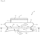
- the extensible member 20 includes the approximately cylindrically-shaped mounting portion 21, a tubular extensible portion 30, and a plurality of first protrusions 41 and second protrusions 42 (see Fig. 3 ).
- the mounting portion 21 is configured to be fitted to the press-fitted surface 18 on the second fixture 16 by press-fitting.
- the extensible portion 30 is continuous with an end portion in the axis direction on the cylinder 2 side of the mounting portion 21.
- the plurality of first protrusions 41 and second protrusions 42 project from an outer peripheral surface of the extensible portion 30.
- the mounting portion 21 includes the claw portion 24 that projects radially outward from an outer peripheral surface of a distal end in the axis direction on the side opposite to the extensible portion 30.
- the claw portion 24 is a part discontinuously disposed in a circumferential direction of the mounting portion 21.
- the extensible portion 30 is a part axially compressed between the axial end surface 3 of the cylinder 2 and the contact surface 17 of the bracket 11 to absorb an impact.
- the outer peripheral surface and the inner peripheral surface of the extensible portion 30 are formed in a bellows shape in which a plurality of mountains and troughs are continuous in the axis direction.
- the outer peripheral surface of the extensible portion 30 is provided with an end surface 31 in the axis direction, a pressure receiving surface 32, a plurality of outer crests 33 as crests of mountains, a plurality of outer roots 34 as bottoms of the troughs, and first contact surfaces 35 and second contact surfaces 36 between the outer crests 33 and the outer roots 34.
- the end surface 31 is continuous with the outer peripheral surface of the mounting portion 21 so as to project radially outward from the mounting portion 21.
- the end surface 31 is a surface pressed against the contact surface 17 of the bracket 11 during large contraction of the shock absorber 1 to be brought into close contact with the contact surface 17.
- the mounting portion 21 axially projects from the end surface 31.
- the pressure receiving surface 32 is a surface that can be in contact with the axial end surface 3 of the cylinder 2.
- the pressure receiving surface 32 is a surface that is in surface contact with the axial end surface 3 of the cylinder 2 during large contraction of the shock absorber 1 to be brought into close contact with the axial end surface 3.
- the inner peripheral surface of the extensible portion 30 includes a plurality of inner crests 37 as crests of mountains and a plurality of inner roots 38 as bottoms of troughs.
- the respective inner crests 37 are positioned radially inward of all of the outer roots 34.
- the respective inner roots 38 are positioned radially inward of all of the outer crests 33. That is, in an imaginary plane perpendicular to the center axis C, the inner root 38 is always positioned on the imaginary plane where the outer crest 33 is positioned.
- the inner crest 37 is always positioned on the imaginary plane where the outer root 34 is positioned.
- the extensible portion 30 axially contracts such that the extensible portion 30 is folded with the inner roots 38 and the outer roots 34 as fulcrums.
- the extensible portion 30 is likely to axially contract.
- a distance from the center axis C to the plurality of outer crests 33 decreases from the end surface 31 side to the pressure receiving surface 32 side.
- a distance from the center axis C to the plurality of outer roots 34, a distance from the center axis C to the plurality of inner crests 37, and a distance from the center axis C to the plurality of inner roots 38 each decrease toward the pressure receiving surface 32 side.
- the outer root 34 and the inner root 38 are point-like on the cross-sectional surface including the center axis C.
- the first contact surface 35 and the second contact surface 36 are parts contactable with one another when the extensible portion 30 axially contracts.
- a part continuous with the end surface 31 side of the outer root 34 is the first contact surface 35.
- a part continuous with the pressure receiving surface 32 side of the outer root 34 is the second contact surface 36.
- the outer crest 33 and the inner crest 37 are parts not in contact with one another when the extensible portion 30 axially contracts and are formed of convex curved lines on the cross-sectional surface including the center axis C.
- the first contact surface 35 includes an inner portion 35a and an outer portion 35b.
- the inner portion 35a is continuous with the whole circumference of the outer root 34.
- the inner portion 35a is formed of a concave curved line on the cross-sectional surface including the center axis C.
- the outer portion 35b connects the whole circumference of the inner portion 35a and the whole circumference of the outer crest 33.
- the outer portion 35b is formed of a convex curved line on the cross-sectional surface including the center axis C.
- a boundary 35c as an inflection point between the inner portion 35a and the outer portion 35b is continuous over the whole circumference of the outer peripheral surface of the first contact surface 35.
- the second contact surface 36 includes an inner portion 36a and an outer portion 36b.
- the inner portion 36a is continuous with the outer root 34 and formed of a concave curved line on the cross-sectional surface including the center axis C.
- the outer portion 36b connects the inner portion 36a and the outer crest 33 and is formed of a convex curved line on the cross-sectional surface including the center axis C.
- a boundary 36c as an inflection point between the inner portion 36a and the outer portion 36b is continuous over the whole circumference of the outer peripheral surface of the second contact surface 36.
- Fig. 3 is a front view of the extensible member 20.
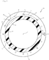
- Fig. 4 is a cross-sectional view of the extensible member 20 along the line IV-IV of Fig. 3.
- Fig. 3 omits the illustration of a part of the extensible portion 30 in the axis direction (a part on the pressure receiving surface 32 side).
- Fig. 3 illustrates the boundaries 35c, 36c by the two-dot chain lines.
- the first protrusion 41 projects from the outer portion 35b, which is positioned radially outward with respect to the boundary 35c in the first contact surface 35.
- the second protrusion 42 projects from the outer portion 36b, which is positioned radially outward with respect to the boundary 36c in the second contact surface 36.
- the first protrusions 41 and the second protrusions 42 are integrally molded with the extensible portion 30.
- the first protrusion 41 and the second protrusion 42 are formed in an approximately hemispherical shape having shapes and dimensions same as one another. That is, a diameter L2 of the hemisphere is approximately same as radial dimensions and circumferential dimensions of the first protrusion 41 and the second protrusion 42.
- the eight first protrusions 41 are disposed at regular intervals in the circumferential direction around the center axis C and disposed in rotational symmetry with respect to the center axis C.
- the eight second protrusions 42 are disposed at regular intervals in the circumferential direction around the center axis C and disposed in rotational symmetry with respect to the center axis C.
- the respective first protrusion 41 and second protrusion 42 have the same radial distance from the center axis C. That is, all of the first protrusions 41 and the second protrusions 42 are disposed on an imaginary circle at a predetermined radius around the center axis C.
- An interval L1 between the first protrusions 41 adjacent in the circumferential direction and the interval L1 of the second protrusions 42 adjacent in the circumferential direction are same.
- the second protrusion 42 is positioned at the center in the circumferential direction of the first protrusions 41 adjacent in the circumferential direction.
- the first protrusion 41 is positioned at the center in the circumferential direction of the second protrusions 42 adjacent in the circumferential direction. That is, the first protrusions 41 and the second protrusions 42 are disposed separately in the circumferential direction in alternation.
- the intervals of the first protrusions 41 and the second protrusions 42 adjacent in the circumferential direction are also the same over the whole circumference.
- the inner crests 37 are positioned radially inward of all of the outer roots 34 and the inner roots 38 are positioned radially inward of all of the outer crests 33.
- the extensible portion 30 made of a thermoplastic elastomer is likely to axially contract such that the extensible portion 30 is folded with the inner roots 38 and the outer roots 34 as fulcrums.
- the first contact surfaces 35 attempt to be in close contact with the second contact surfaces 36.
- the first protrusion 41 and the second protrusion 42 project from the first contact surface 35 and the second contact surface 36, respectively.
- the first contact surface 35 and the second contact surface 36 are less likely to be in close contact around the first protrusion 41 and the second protrusion 42.
- the extensible member 20 allows facilitating the entrance of air between the first contact surface 35 and the second contact surface 36 from around the first protrusion 41 and the second protrusion 42.
- the extensible member 20 allows abnormal noise during the extension and contraction of the extensible portion 30 to be less likely to occur.
- the extensible portion 30 contracts by being folded with the outer roots 34 as the fulcrums, the amount of deformation of the inner portions 35a, 36a formed of the concave curved lines becomes smaller than the amount of deformation of the outer portions 35b, 36b formed of the convex curved lines.
- the first protrusion 41 and the second protrusion 42 are disposed in the outer portions 35b, 36b, respectively.
- the extensible member 20 can suppress the concentration of stress around the first protrusion 41 and the second protrusion 42 during the extension and contraction of the extensible portion 30.
- the extensible member 20 allows suppressing reduction in durability of the extensible portion 30 caused by disposing the first protrusions 41 and the second protrusions 42.
- thermoplastic elastomer used in this embodiment a large strain is likely to remain (plastic deformation is likely to occur) during a contraction for the first time after molding, compared with rubber.
- an amount of plastic deformation of the inner portions 35a, 36a, which easily deform during the extension and contraction, is large and the amount of plastic deformation of the outer portions 35b, 36b, which are less likely to deform during the extension and contraction, is small.
- the first protrusion 41 and the second protrusion 42 are disposed in the outer portions 35b, 36b, respectively, where the amount of plastic deformation is small.
- the way of deformation of the extensible portion 30 after the plastic deformation is less likely to change according to the presence/absence of the first protrusion 41 and the second protrusion 42.
- a buffering property and durability of the extensible portion 30 according to the way of deformation become approximately similar between the cases where the first protrusions 41 and the second protrusions 42 are present and absent.
- the buffering property and durability of the extensible portion 30 of the extensible member 20 including the first protrusions 41 and the second protrusions 42 can be easily set.
- the outer portions 35b, 36b are positioned separately from the outer root 34 outward in the radial direction.
- the first contact surface 35 is separated from the second contact surface 36 in the order from radially outward in many cases. That is, the first contact surface 35 is separated from the second contact surface 36 in the order from the outer portions 35b, 36b and the inner portions 35a, 36a in many cases.
- air is likely to quickly enter between the first contact surfaces 35 and the second contact surfaces 36 by the first protrusions 41 and the second protrusions 42.
- the extensible member 20 allows abnormal noise during the extension and contraction of the extensible portion 30 to be more less likely to occur.
- the respective first protrusions 41 and second protrusions 42 are disposed in rotational symmetry with respect to the center axis C.
- the way of deformation of the extensible portion 30 during the extension and contraction is close to be uniform over the circumferential direction.
- the concentration of stress at a part of the extensible portion 30 in the circumferential direction during the extension and contraction can be suppressed.
- the extensible member 20 allows further suppressing the reduction in durability of the extensible portion 30 caused by disposing the first protrusions 41 and the second protrusions 42.
- the respective radial distances from the center axis C to the plurality of first protrusions 41 and second protrusions 42 are same.
- the extensible member 20 allows the way of deformation of the extensible portion 30 to be further close to be uniform over the circumferential direction.
- the plurality of respective first protrusions 41 and second protrusions 42 are disposed at regular intervals in the circumferential direction.
- the extensible member 20 allows the way of deformation of the extensible portion 30 to be further close to be uniform over the circumferential direction.
- the plurality of first protrusions 41 and second protrusions 42 are disposed separately in the circumferential direction in alternation in the first contact surfaces 35 and the second contact surfaces 36 contactable with one another.
- the way of deformation of the first contact surface 35 and the way of deformation of the second contact surface 36 are close to be uniform.
- the concentration of stress on one of the first contact surface 35 or the second contact surface 36 can be suppressed.
- the extensible member 20 allows further suppressing the reduction in durability of the extensible portion 30 caused by disposing the first protrusions 41 and the second protrusions 42.
- the interval L1 between the first protrusions 41 is the same as the interval L1 between the second protrusions 42.
- the way of deformation of the first contact surface 35 and the way of deformation of the second contact surface 36 during the extension and contraction of the extensible portion 30 are further close to be uniform.
- the first protrusion 41 and the second protrusion 42 have the shapes and dimensions same as one another. With the extensible member 20, the way of deformation of the first contact surface 35 and the way of deformation of the second contact surface 36 during the extension and contraction of the extensible portion 30 can be further close to be uniform.
- the radial distances from the center axis C to all of the first protrusions 41 and the second protrusions 42 are same, and the intervals between the first protrusions 41 and the second protrusions 42 are same over the whole circumference.
- the first protrusion 41 and the second protrusion 42 are formed in the approximately hemispherical shape in which the circumferential dimensions L2 and the radial dimensions L2 are same.
- the extensible member 20 compared with a case where the first protrusion 41 and the second protrusion 42 have the circumferential dimensions greater than the radial dimensions, when the first protrusion 41 and the second protrusion 42 are separated from the first contact surface 35 and the second contact surface 36 at once after being in close contact, air can quickly enter between the first contact surface 35 and the second contact surface 36.
- the extensible member 20 allows abnormal noise during the extension and contraction to be more less likely to occur.
- a second embodiment will be described with reference to Fig. 5 , Fig. 6(a), and Fig. 6(b) .
- the first protrusion 41 and the second protrusion 42 have the approximately hemispherical shape has been described.
- a case where a circumferential dimension L3 of a first protrusion 54 and a second protrusion 55 is formed larger than the radial dimension L2 of the first protrusion 54 and the second protrusion 55 will be described. Same reference numerals are given to parts same as those of the first embodiment and the description thereof will be omitted.
- Fig. 5 is a partial cross-sectional view of an extensible member 50 in the second embodiment.
- the right side with respect to the center axis C in the paper is the cross-sectional view of the extensible member 50 and the left side with respect to the center axis C in the paper is a front view of the extensible member 50.
- Fig. 6(a) is a cross-sectional view of the extensible member 50 along the line VIa-VIa of Fig. 5 .
- Fig. 6(b) is a cross-sectional view of the extensible member 50 along the line VIb-VIb of Fig. 6(a).
- Fig. 6(b) illustrates a first contact surface 52 at a part from which the first protrusion 54 projects by the two-dot chain line.
- the extensible member 50 includes the mounting portion 21, a tubular extensible portion 51 continuous with the end portion in the axis direction of the mounting portion 21, and the plurality of first protrusions 54 and second protrusions 55 projecting from an outer peripheral surface of the extensible portion 51.
- the extensible member 50 is a member made of a thermoplastic elastomer in which respective portions are integrally formed. The extensible member 50 is sandwiched between the axial end surface 3 of the cylinder 2 and the contact surface 17 of the bracket 11 and compressed in the axis direction to absorb an impact during compression by an elastic force from the extensible member 50.
- An outer peripheral surface of the extensible portion 51 is provided with the end surface 31, the pressure receiving surface 32, the outer crests 33, the outer roots 34, and first contact surfaces 52 and second contact surfaces 53 that connect the outer crests 33 and the outer roots 34.
- An inner peripheral surface of the extensible portion 51 is provided with the inner crests 37 and the inner roots 38.
- the first contact surface 52 and the second contact surface 53 are parts contactable with one another when the extensible portion 51 axially contracts.
- a part continuous with the end surface 31 side of the outer root 34 is the first contact surface 52.
- a part continuous with the pressure receiving surface 32 side of the outer root 34 is the second contact surface 53.
- the first contact surface 52 includes the inner portion 35a continuous with the whole circumference of the outer root 34 and an outer portion 52b that connects the whole circumference of the inner portion 35a and the whole circumference of the outer crest 33.
- the outer portion 52b includes a planar portion 52d continuous with the inner portion 35a and a convex surface portion 52e that connects the planar portion 52d and the outer crest 33.
- the planar portion 52d is formed of a straight line on the cross-sectional surface including the center axis C.
- the convex surface portion 52e is formed of a convex curved line on the cross-sectional surface including the center axis C.
- the second contact surface 53 includes the inner portion 36a continuous with the whole circumference of the outer root 34 and an outer portion 53b that connects the whole circumference of the inner portion 36a and the whole circumference of the outer crest 33.
- the outer portion 53b includes a planar portion 53d continuous with the inner portion 36a and a convex surface portion 53e that connects the planar portion 53d and the outer crest 33.
- the planar portion 53d is formed of a straight line on the cross-sectional surface including the center axis C.
- the convex surface portion 53e is formed of a convex curved line on the cross-sectional surface including the center axis C.
- Boundaries 52c, 53c between the inner portions 35a, 36a and the outer portions 52b, 53b are continuous over the whole circumference of the outer peripheral surface of the extensible portion 51 and indicated by the two-dot chain lines in Fig. 5 .
- the first protrusion 54 projects from the planar portion 52d in the outer portion 52b of the first contact surface 52.
- the second protrusion 55 projects from the planar portion 53d in the outer portion 53b of the second contact surface 53.
- the first protrusions 54 and the second protrusions 55 are integrally molded with the extensible portion 51.
- the first protrusions 54 are arc-shaped parts around the center axis C.
- the first protrusion 54 is formed by extending the hemispherical first protrusion 41 of the first embodiment in the circumferential direction with the radial dimension L2 of the first protrusion 41 maintained.
- the four first protrusions 54 are disposed at regular intervals in the circumferential direction around the center axis C and disposed in rotational symmetry with respect to the center axis C. Respective radial distances from the center axis C to the plurality of first protrusions 54 are same.
- the second protrusion 55 is disposed at the center in the circumferential direction of the first protrusions 54 adjacent in the circumferential direction.
- the second protrusions 55 are formed in an arc shape around the center axis C.
- the four second protrusions 55 are disposed at regular intervals in the circumferential direction around the center axis C and disposed in rotational symmetry with respect to the center axis C. Respective radial distances from the center axis C to the plurality of second protrusions 55 are same.
- the radial distance from the center axis C to the first protrusion 54 and the radial distance from the center axis C to the second protrusion 55 are mutually same.
- An interval between the first protrusions 54 adjacent in the circumferential direction and an interval between the second protrusions 55 adjacent in the circumferential direction are same.
- the first protrusions 54 and the second protrusions 55 are disposed to be separated in the circumferential direction in alternation.
- the intervals of the first protrusions 54 and the second protrusions 55 adjacent in the circumferential direction are also the same over the whole circumference.
- the first protrusion 54 and the second protrusion 55 project from the outer portions 52b, 53b where the amount of deformation during the extension and contraction of the extensible portion 51 is small, respectively.
- the extensible member 50 allows abnormal noise during the extension and contraction to be less likely to occur with the first protrusions 54 and the second protrusions 55 and allows suppressing the reduction in durability of the extensible portion 51 caused by disposing the first protrusions 54 and the second protrusions 55.
- planar portions 52d, 53d are the straight lines on the cross-sectional surface including the center axis C, the planar portion 52d and the planar portion 53d are likely to be in close contact during the contraction of the extensible portion 51.
- the planar portions 52d, 53d are less likely to be in close contact during the contraction of the extensible portion 51.
- the extensible member 50 allows abnormal noise during the extension and contraction to be more less likely to occur.
- first protrusion 54 The shape and dimensions of the first protrusion 54 will be described in further detail with reference to Fig. 6(a) and Fig. 6(b) . Since the shape and the dimensions of the second protrusion 55 are same as the shape and the dimensions of the first protrusion 54, a part of the description of the shape and the dimensions of the second protrusion 55 will be omitted.
- the arc-shaped first protrusion 54 around the center axis C has the circumferential dimension L3 larger than the radial dimension L2.
- the first contact surfaces 52 and the second contact surfaces 53 are less likely to be in close contact at a further wide range.
- abnormal noise during the extension and contraction of the extensible portion 51 can be sufficiently less likely to occur while the numbers of the first protrusions 54 and the second protrusions 55 are reduced.
- a local load is applied by point from the first protrusion 41 and the second protrusion 42 to the first contact surface 35 and the second contact surface 36.
- a linear load is applied from the first protrusion 54 and the second protrusion 55 to the first contact surface 52 and the second contact surface 53.
- the extensible member 50 allows facilitating a dispersion of the load applied from the first protrusion 54 and the second protrusion 55 to the first contact surface 52 and the second contact surface 53. That is, concentration of stress on the extensible portion 51 around the first protrusions 54 and the second protrusions 55 can be suppressed.
- the extensible member 50 can ensure the durability of the extensible portion 51.
- Plastic deformation of the extensible portion 51 in accordance with cyclic deformation becomes large from the peripheral area of the part where the amount of deformation is large among the first protrusion 54 and the second protrusion 55.
- the durability of the extensible portion 51 is reduced and the buffering property is deteriorated.
- the circumferential dimension L3 of the first protrusion 54 and the second protrusion 55 is larger than the radial dimension L2 of the first protrusion 54 and the second protrusion 55.
- a difference in amount of deformation between the first protrusion 54 and the second protrusion 55 in the length direction decreases. Since the first protrusions 54 and the second protrusions 55 are formed in the arc shape around the center axis C, the difference in amount of deformation between the first protrusion 54 and the second protrusion 55 in the length direction further decreases.
- the extensible member 50 allows suppressing the concentration of stress around a part of the first protrusion 54 and the second protrusion 55 in the length direction during the extension and contraction of the extensible portion 51.
- the extensible member 50 allows suppressing the reduction in durability and deterioration of the buffering property of the extensible portion 51.
- Fig. 6(b) illustrates a cross-sectional surface along the first protrusion 54 and a cross-sectional surface perpendicular to the first contact surface 52 of a part where the first protrusion 54 is disposed.
- the first protrusion 54 includes a center portion 56 where a thickness T of the first protrusion 54 (a distance from the first contact surface 52 to a distal end of the first protrusion 54) is approximately constant.
- the center portion 56 is disposed at the center portion in the circumferential direction of the first protrusion 54 and has a circumferential dimension formed to be sufficiently larger than the radial dimension L2 of the first protrusion 54.
- the second protrusion 55 also includes the center portion 56.
- a third embodiment will be described with reference to Fig. 7(a) and Fig. 7(b) .
- the cases where the first protrusions 41, 54 and the second protrusions 42, 55 project from the first contact surfaces 35, 52 and the second contact surfaces 36, 53, respectively, have been described.
- the third embodiment a case where protrusions 64 project from only first contact surfaces 62 will be described. Same reference numerals are given to parts same as those of the first embodiment and the description thereof will be omitted.
- Fig. 7(a) is a partial cross-sectional view of an extensible member 60 of the third embodiment.
- the right side with respect to the center axis C in the paper is the cross-sectional view of the extensible member 60 and the left side with respect to the center axis C in the paper is a front view of the extensible member 60.
- Fig. 7(b) is cross-sectional view of the extensible member 60 perpendicular to a first contact surface 62 as a part where the protrusion 64 is disposed and taken along the protrusion 64.
- Fig. 7(b) illustrates the first contact surface 62 as the part from which the protrusion 64 projects by the two-dot chain line.
- the extensible member 60 includes the mounting portion 21, a tubular extensible portion 61 continuous with the end portion in the axis direction of the mounting portion 21, and the plurality of protrusions 64 projecting from an outer peripheral surface of the extensible portion 61.
- the extensible member 60 is a member made of a thermoplastic elastomer in which respective portions are integrally formed.
- the extensible member 60 is sandwiched between the axial end surface 3 of the cylinder 2 and the contact surface 17 of the bracket 11 and compressed in the axis direction to absorb an impact during compression by an elastic force from the extensible member 60.
- An outer peripheral surface of the extensible portion 61 is provided with the end surface 31, the pressure receiving surface 32, the outer crests 33, the outer roots 34, and the first contact surfaces 62 and second contact surfaces 63 that connect the outer crests 33 and the outer roots 34.
- An inner peripheral surface of the extensible portion 61 is provided with the inner crests 37 and the inner roots 38.
- the first contact surface 62 and the second contact surface 63 are parts contactable with one another when the extensible portion 61 axially contracts.
- a part continuous with the end surface 31 side of the outer root 34 is the first contact surface 62.
- a part continuous with the pressure receiving surface 32 side of the outer root 34 is the second contact surface 63.
- the first contact surface 62 includes the inner portion 35a continuous with the whole circumference of the outer root 34 and an outer portion 62b that connects the whole circumference of the inner portion 35a and the whole circumference of the outer crest 33.
- the outer portion 62b includes a perpendicular portion 62d continuous with the inner portion 35a and a convex surface portion 62e that connects the perpendicular portion 62d and the outer crest 33.
- the perpendicular portion 62d is formed of a straight line perpendicular to the center axis C on the cross-sectional surface including the center axis C.
- the convex surface portion 62e is formed of a convex curved line on the cross-sectional surface including the center axis C.
- the second contact surface 63 includes the inner portion 36a continuous with the whole circumference of the outer root 34 and an outer portion 63b that connects the whole circumference of the inner portion 36a and the whole circumference of the outer crest 33.
- the outer portion 63b includes a perpendicular portion 63d continuous with the inner portion 35a and a convex surface portion 63e that connects the perpendicular portion 63d and the outer crest 33.
- the perpendicular portion 63d is formed of a straight line perpendicular to the center axis C on the cross-sectional surface including the center axis C.
- the convex surface portion 63e is formed of a convex curved line on the cross-sectional surface including the center axis C.
- Boundaries 62c, 63c between the inner portions 35a, 36a and the outer portions 62b, 63b are continuous over the whole circumference of the outer peripheral surface of the extensible portion 61.
- the protrusion 64 projects from the perpendicular portion 62d in the outer portion 62b of the first contact surface 62 and is integrally molded with the extensible portion 61.
- the protrusions 64 are disposed similarly to the first protrusions 54 of the second embodiment illustrated in Fig. 6(a) .
- the protrusions 64 are arc-shaped parts around the center axis C.
- the four protrusions 64 are disposed at regular intervals in the circumferential direction around the center axis C and disposed in rotational symmetry with respect to the center axis C. Respective radial distances from the center axis C to the plurality of protrusions 64 are same.
- the extensible member 60 allows the first contact surfaces 62 and the second contact surfaces 63 to be less likely to be in close contact around the protrusions 64 during the extension and contraction of the extensible portion 61.
- air is likely to enter between the first contact surface 62 and the second contact surface 63 from around the protrusion 64.
- the extensible member 60 allows abnormal noise during the extension and contraction to be less likely to occur.
- the protrusion 64 projects from the outer portion 62b where the amount of deformation during the extension and contraction of the extensible portion 61 is small in the extensible member 60.
- the extensible member 60 allows suppressing the reduction in durability of the extensible portion 61 caused by disposing the protrusions 64.
- the perpendicular portions 62d, 63d are straight lines perpendicular to the center axis C on the cross-sectional surface including the center axis C.
- the insides in the radial direction of the mutual perpendicular portions 62d, 63d are likely to be separated first.
- the protrusions 64 are disposed on the perpendicular portions 62d, 63d, air is likely to enter the insides in the radial direction of the perpendicular portions 62d, 63d during the extension of the extensible portion 61.
- the extensible member 60 allows abnormal noise during the extension and contraction of the extensible portion 61 to be more less likely to occur.
- the protrusion 64 has a radial dimension same as the radial dimension L2 of the first protrusion 54 of the second embodiment. As illustrated in Fig. 7(b) , a circumferential dimension L4 of the protrusion 64 is formed larger than the radial dimension L2 of the protrusion 64.
- the extensible member 60 allows abnormal noise during the extension and contraction of the extensible portion 61 to be less likely to occur sufficiently with the reduced number of protrusions 64 and also allows suppressing the reduction in durability and deterioration of the buffering property of the extensible portion 61.
- the circumferential dimension L4 of the protrusion 64 is formed larger than the circumferential dimension L3 of the first protrusion 54 and the second protrusion 55 of the second embodiment.
- the circumferential dimension L4 of the protrusion 64 is about twice the circumferential dimension L3 of the first protrusion 54 and the second protrusion 55.
- the first contact surfaces 62 and the second contact surfaces 63 are less likely to be in close contact sufficiently during the contraction of the extensible portion 61 with the protrusions 64.
- the extensible member 60 allows abnormal noise during the extension and contraction of the extensible portion 61 to be less likely to occur sufficiently.
- Fig. 7(b) illustrates a cross-sectional surface along the protrusion 64 and a cross-sectional surface perpendicular to the first contact surface 62 as the part where the protrusion 64 is disposed.
- the distance from the first contact surface 62 to the distal end of the protrusion 64 gradually shortens from the center in the circumferential direction to both ends in the circumferential direction.
- the protrusion 64 is gradually separated from the second contact surface 63 from both ends in the circumferential direction to the center in the circumferential direction of the protrusion 64.
- air passes through a clearance where the protrusion 64 is separated from the second contact surface 63 and can quickly enter between the first contact surface 62 and the second contact surface 63 in the center axis C side of the protrusion 64. That is, the air quickly enters between the first contact surface 62 and the second contact surface 63 without the air coming around from both ends in the circumferential direction of the protrusion 64.
- the extensible member 60 allows abnormal noise during the extension and contraction of the extensible portion 61 to be more less likely to occur.
- FIG. 8 is a front view of an extensible member 70 of the fourth embodiment.
- Fig. 9 is a cross-sectional view of the extensible member 70 along the line IX-IX of Fig. 8 .
- the extensible member 70 includes the mounting portion 21, the extensible portion 30, and the protrusion 72 projecting from the outer portion 35b in the first contact surface 35 of the extensible portion 30.
- the extensible member 70 is a member made of a thermoplastic elastomer in which respective portions are integrally formed.
- the extensible member 70 is sandwiched between the axial end surface 3 of the cylinder 2 and the contact surface 17 of the bracket 11 and compressed in the axis direction to absorb an impact during compression by an elastic force from the extensible member 70.
- the protrusion 72 projects from the outer portion 35b where the amount of deformation during the extension and contraction of the extensible portion 30 is small.
- the extensible member 70 allows abnormal noise during the extension and contraction of the extensible portion 30 to be less likely to occur with the protrusion 72 and also allows suppressing the reduction in durability of the extensible portion 30 caused by disposing the protrusion 72.
- the protrusion 72 is a strip-shaped part formed continuously over the whole circumference around the center axis C. Since this allows the first contact surface 35 and the second contact surface 36 to be less likely to be in close contact at the further wide range during the contraction of the extensible portion 30, the extensible member 70 allows abnormal noise during the extension and contraction of the extensible portion 30 to be more less likely to occur.
- the protrusion 72 smoothly changes its radial distance to the center axis C along the circumferential direction. Specifically, in the protrusion 72, a part where the radial distance from the center axis C becomes a maximum value L5 and a part where the radial distance from the center axis C becomes a minimum value L6 are provided in alternation at regular intervals in the circumferential direction. Viewing from the axis direction of the center axis C, the part with the maximum value L5 in the protrusion 72 is formed in a convex curved line shape to outside in the radial direction.
- the part with the minimum value L6 in the protrusion 72 is formed in a convex curved line shape to inside in the radial direction.
- the respective convex curved lines are smoothly connected to one another.
- the first contact surfaces 35 and the second contact surfaces 36 are gradually separated mainly from radially outward.
- the protrusion 72 is gradually separated from the second contact surfaces 36 from the part with the maximum value L5, which is positioned outermost in the circumferential direction in the protrusion 72, to the part with the minimum value L6.
- the extensible member 70 allows reducing the separation of the protrusion 72 from the second contact surfaces 36 at once.
- the extensible member 70 allows suppressing abnormal noise caused by the close contact of the protrusion 72 with the second contact surfaces 36.
- the parts with the maximum value L5 and the parts with the minimum value L6 are disposed in alternation at regular intervals in the protrusion 72.
- the extensible member 70 allows disposing the positions where the protrusion 72 has already been separated from the second contact surfaces 36 and the positions where the protrusion 72 is in still close contact with the second contact surfaces 36 to be approximately uniform over the circumferential direction. This allows suppressing the change in the way of deformation of the extensible portion 30 in the circumferential direction caused by, for example, a pressure of air passing through the part where the protrusion 72 has already been separated from the second contact surface 36.
- the extensible member 70 allows the way of deformation of the extensible portion 30 to be close to uniform over the circumferential direction.
- the extensible member 70 allows suppressing the reduction in durability of the extensible portion 30 caused by disposing the protrusion 72.
- the parts with the maximum value L5 and the parts with the minimum value L6 are formed in the curved line shape, and the radial distance from the center axis C to the protrusion 72 smoothly changes along the circumferential direction. This suppresses the concentration of stress on the parts with the maximum value L5 and the parts with the minimum value L6 during the extension and contraction of the extensible portion 30, compared with a case where the parts with the maximum value L5 and the parts with the minimum value L6 form squares in the protrusion 72.
- the extensible member 70 allows suppressing the reduction in durability of the protrusion 72 and the extensible portion 30.
- the present invention has been described based on the above-mentioned embodiments, the present invention is not limited to the embodiments by any means. It can be easily inferred that various improvements and modifications are possible within a scope not departing from the gist of the present invention.
- the shapes and the dimensions of the respective portions of the bracket 11 and the extensible members 20, 50, 60, 70 may be changed as necessary.
- the respective radial distances from the center axis C to the plurality of outer crests 33 may be set to be the same.
- the distances from the center axis C may be set to be the same.
- the convex surface portions 52e, 53e, 62e, 63e may be omitted, and outer portions may be formed by the planar portions 52d or the perpendicular portions 62d formed of straight lines on the cross-sectional surface including the center axis C.
- the outer crests 33 may be formed by straight lines approximately parallel to the center axis C on the cross-sectional surface including the center axis C.
- the first protrusions 41, 54, the second protrusions 42, 55, and the protrusions 64, 72 may be disposed on the convex surface portions 52e, 53e, 62e, 63e in the outer portions 52b, 53b, 62b, 63b.
- the first contact surfaces 52, 62 are separated from the second contact surfaces 53, 63 in the order from radially outward in many cases.
- first protrusions 41, 54, the second protrusions 42, 55, and the protrusions 64, 72 are disposed on the convex surface portions 52e, 53e, 62e, 63e.
- air is likely to enter quickly between the first contact surfaces 52, 62 and the second contact surfaces 53, 63.
- Abnormal noise during the extension and contraction of the extensible portions 51, 61 is less likely to occur.
- the present invention is not necessarily limited to the embodiments.
- the extensible member only needs to be a member that includes the extensible portion 30, 51, 61 having the outer peripheral surface and the inner peripheral surface in the bellows shape in which the mountains and the troughs are continuous in the axis direction and extends and contracts in the axis direction.
- the extensible member may be, for example, a dust cover that covers the outer periphery of the shock absorber 1.
- the present invention is preferably applied to the extensible member as the stopper.
- first contact surfaces 35, 52, 62 and the second contact surfaces 36, 53, 63 are in instantaneously close contact and then separated in the stopper that absorbs an impact by extension and contraction of the extensible member in the axis direction, abnormal noise during the extension and contraction of the extensible member tends to be a problem.
- first protrusions 41, 54, the second protrusions 42, 55, and the protrusions 64, 72 are in the extensible member that absorbs an impact, abnormal noise during the extension and contraction of the extensible member, which tends to be problem, is suppressed.
- first protrusions 41, 54 and the second protrusions 42, 55 are disposed separately in alternation in the circumferential direction have been described in the first and second embodiments, the present invention is not necessarily limited to the embodiments.
- the first protrusions 41, 54 and the second protrusions 42, 55 may be disposed in contact with one another during the extension and contraction of the extensible portions 30, 51.
- the first protrusions 41, 54, the second protrusions 42, 55, and the protrusions 64, 72 may be randomly disposed.
- the fine first protrusions 41, 54, second protrusions 42, 55, and protrusions 64, 72 may be formed with unevennesses formed on a mold for forming the first contact surfaces 35, 52, 62 and the second contact surfaces 36, 53, 63 by, for example, etching, sand-blasting, and shot-blasting.
- first protrusions 41, 54 project from the first contact surfaces 35, 52 and the second protrusions 42, 55 project from the second contact surfaces 36, 53
- the present invention is not necessarily limited to the embodiments.
- the first protrusions (protrusions) 41, 54 may project only from the first contact surfaces 35, 52, 62 and the second protrusions 42, 55 may be omitted.
- the second protrusions (protrusions) 42, 55 may project only from the second contact surfaces 36, 53, 63 and the first protrusions 41, 54 may be omitted.
- the protrusions 64, 72 of the third and fourth embodiments may project only from the second contact surfaces 36, 53, 63.
- the protrusions (first protrusions) 64 may project from the first contact surfaces 35, 52, 62, the protrusions (second protrusions) 64 may project from the second contact surfaces 36, 53, 63.
- the protrusion (first protrusion) 72 projects from the first contact surfaces 35, 52, 62
- the protrusion (second protrusion) 72 may project from the second contact surfaces 36, 53, 63.
- the part with the maximum value L5 in the first protrusion 72 and the part with the maximum value L5 in the second protrusion 72 are preferably disposed separately in the circumferential direction.
- the protrusion 72 which is continuous over the whole circumference, is preferably disposed on only any one of the first contact surfaces 35, 52, 62 or the second contact surfaces 36, 53, 63. Since the load applied from the protrusion 72 to the first contact surfaces 35, 52, 62 and the second contact surfaces 36, 53, 63 can be close to be uniform over the circumferential direction, the deterioration of durability of the extensible portions 30, 51, 61 caused by the protrusion 72 is suppressed.
Landscapes
- Engineering & Computer Science (AREA)
- General Engineering & Computer Science (AREA)
- Mechanical Engineering (AREA)
- Fluid-Damping Devices (AREA)
- Springs (AREA)
Abstract
Description
- The present invention relates to an extensible member that allows abnormal noise during extension and contraction to be less likely to occur.
- There has been known an extensible member that includes a tubular extensible portion made of a thermoplastic elastomer having an inner peripheral surface and an outer peripheral surface in a bellows shape. For example, the extensible member is a bump stopper disposed between a cylinder of a shock absorber and a bracket secured to a piston rod projecting from the cylinder (Patent Literature 1). The bump stopper absorbs an impact of the shock absorber during a large contraction by extension and contraction of an extensible portion. In the extensible member disclosed in
Patent Literature 1, roots of an inner peripheral surface of the extensible portion are positioned radially inward of all crests of an outer peripheral surface of the extensible portion. Crests of the inner peripheral surface of the extensible portion are positioned radially inward of all roots of the outer peripheral surface of the extensible portion. This is because to facilitate deformation of the extensible portion made of a thermoplastic elastomer. - [Patent Literature 1]
JP-A No. 2016-223632 - However, in the conventional technique, when the extensible portion is contracted and the extensible portion is folded with the roots of the inner peripheral surface and the roots of the outer peripheral surface as fulcrums, two surfaces opposed in an axis direction are brought into close contact. The conventional technique has a problem that air is less likely to enter between the two surfaces in close contact when the two surfaces in close contact are separated at once, and therefore abnormal noise is likely to occur.
- The present invention has been made to solve the above-described problem. An object of the present invention is to provide an extensible member that allows abnormal noise during extension and contraction of an extensible portion to be less likely to occur.
- An extensible member of the present invention includes a tubular extensible portion and at least one protrusion. The tubular extensible portion made of a thermoplastic elastomer has an inner peripheral surface and an outer peripheral surface in a bellows shape in which mountains and troughs are continuous in an axis direction. The at least one protrusion projects from the outer peripheral surface. The outer peripheral surface includes outer crests as crests of mountains, outer roots as bottoms of troughs, and first contact surfaces and second contact surfaces between the outer crests and the outer roots. The first contact surfaces and second contact surfaces are positioned to be contactable with one another when the extensible portion axially contracts. The inner peripheral surface includes inner crests as crests of mountains and inner roots as bottoms of troughs. The inner crests are positioned radially inward of all of the outer roots. The inner roots are positioned radially inward of all of the outer crests. The protrusion is positioned on at least one of the first contact surfaces and the second contact surfaces.
- The protrusion may include a plurality of first protrusions that project from the first contact surfaces and a plurality of second protrusions that project from the second contact surfaces. The plurality of respective first protrusions and second protrusions may be disposed at regular intervals around the center axis of the extensible portion. When viewed in the axial direction of the center axis of the extensible portion, all of the first protrusions and the second protrusions may be disposed on an imaginary circle at a predetermined radius around the center axis. The second protrusion may be positioned at a center in a circumferential direction of the first protrusions adjacent in the circumferential direction. The first protrusion may be positioned at a center in the circumferential direction of the second protrusions adjacent in the circumferential direction.
- With the extensible member according to
claim 1, the inner crests are positioned radially inward of all of the outer roots, and the inner roots are positioned radially inward of all of the outer crests. The extensible portion made of the thermoplastic elastomer is likely to axially contract such that the extensible portion is folded with the inner roots and the outer roots as fulcrums. When the extensible portion is folded, the first contact surfaces attempt to be in close contact with the second contact surfaces. However, since the at least one protrusion is positioned on at least one of the first contact surfaces and the second contact surfaces, the first contact surfaces and the second contact surfaces are less likely to be in close contact around the protrusion. When the first contact surface and the second contact surface are separated at once after being in close contact, the extensible member allows facilitating an entrance of air between the first contact surface and the second contact surface from around the protrusion. The extensible member allows abnormal noise during extension and contraction of the extensible portion to be less likely to occur. - The first contact surface and the second contact surface of the extensible member according to
claim 2 includes an inner portion and an outer portion. The inner portion is formed of a concave curved line continuous with the outer root on a cross-sectional surface including the center axis of the extensible portion. The outer portion is formed of at least one of a straight line or a convex curved line connecting outside in a radial direction of the inner portion and the outer crest on the cross-sectional surface including the center axis of the extensible portion. During the extension and contraction of the extensible portion, an amount of deformation of the outer portion becomes smaller than an amount of deformation of the inner portion. The protrusion is positioned on the outer portion where the amount of deformation is small. Although depending on a size of the protrusion, compared with a case where the protrusion is positioned on the inner portion where the amount of deformation is large, the extensible member allows stress to be less likely to concentrate on the extensible portion around the protrusion during the extension and contraction of the extensible portion. In addition to the effect ofclaim 1, the extensible member allows suppressing reduction in durability of the extensible portion caused by disposing the protrusion. - The protrusion is positioned on the outer portion at a position separated radially outward from the outer root with respect to the inner portion. The extensible member allows facilitating quick entrance of air between the first contact surface and the second contact surface with the protrusion during the extension and contraction of the extensible portion. The extensible member allows abnormal noise during the extension and contraction of the extensible portion to be more less likely to occur.
- The outer portion of the extensible member according to
claim 3 includes a perpendicular portion formed of a straight line perpendicular to the center axis and continuous with the inner portion on the cross-sectional surface including the center axis of the extensible portion. When the extensible portion extends after the contraction, the perpendicular portions in contact are likely to be separated from radially inward first. Since the protrusion is positioned on the perpendicular portion, air is likely to enter radially inward of the perpendicular portion during the extension of the extensible portion. In addition to the effect ofclaim 2, the extensible member allows abnormal noise during the extension and contraction of the extensible portion to be more less likely to occur. - In the extensible member according to
claim 4, the protrusions are disposed in rotational symmetry with respect to the center axis of the extensible portion. A way of the deformation of the extensible portion is close to be uniform over the circumferential direction. The stress is less likely to concentrate on a part in the circumferential direction of the extensible portion during the extension and contraction. In addition to the effect of any ofclaims 1 to 3, the extensible member allows further suppressing the reduction in durability of the extensible portion caused by disposing the protrusion. - The protrusion of the extensible member according to claim 5 includes a plurality of first protrusions that project from the first contact surfaces and a plurality of second protrusions that project from the second contact surfaces. The plurality of first protrusions and the second protrusions are disposed separately in alternation in the circumferential direction on the first contact surfaces and the second contact surfaces contactable with one another. During the extension and contraction of the extensible portion, a way of deformation of the first contact surface and a way of deformation of the second contact surface are close to be uniform. The concentration of stress on one of the first contact surface or the second contact surface can be suppressed. In addition to the effect of any of
claims 1 to 4, the extensible member allows further suppressing the reduction in durability of the extensible portion caused by disposing the protrusions. - With the extensible member according to claim 6, a circumferential dimension of the protrusion is larger than a radial dimension of the protrusion. During the contraction of the extensible portion, the first contact surfaces and the second contact surfaces are less likely to be in close contact at a further wide range. During the contraction of the extensible portion, the amounts of deformations of the first contact surface and the second contact surface are likely to differ according to radial positions. Compared with a case where the radial dimension of the protrusion is larger than the circumferential dimension of the protrusion, the extensible member allows decreasing the difference in amount of deformation of the protrusions in length directions of the protrusions. The extensible member allows suppressing the concentration of stress around a part of the protrusion in the length direction during the extension and contraction of the extensible portion. In addition to the effect of any of
claims 1 to 5, the extensible member allows further suppressing the reduction in durability of the extensible portion caused by disposing the protrusions. - The protrusion of the extensible member according to claim 7 is continuous over a whole circumference of only any one of the first contact surfaces or the second contact surfaces. During the contraction of the extensible portion, the first contact surfaces and the second contact surfaces are less likely to be in close contact at a further wide range. A radial distance from the center axis of the extensible portion to the protrusion changes along the circumferential direction. When the protrusion is separated from the first contact surfaces or the second contact surfaces after the protrusion is in close contact with the first contact surfaces or the second contact surfaces over the whole circumference, the first contact surfaces or the second contact surfaces are gradually separated from outside in the circumferential direction of the protrusion. In addition to the effect of any of
claims 1 to 4, the extensible member allows further suppressing abnormal noise caused by the close contact between the first contact surface and the second contact surface and the close contact of the protrusion with the first contact surfaces or the second contact surfaces can be suppressed. -
- [
Fig. 1] Fig. 1 is a cross-sectional view of a stopper unit that includes an extensible member in a first embodiment. - [
Fig. 2] Fig. 2 is a partially enlarged cross-sectional view of the stopper unit that enlarges a part II ofFig. 1 . - [
Fig. 3] Fig. 3 is a front view of the extensible member. - [
Fig. 4] Fig. 4 is a cross-sectional view of the extensible member along the line IV-IV ofFig. 3 . - [
Fig. 5] Fig. 5 is a partial cross-sectional view of an extensible member in a second embodiment. - [
Fig. 6] Fig. 6(a) is a cross-sectional view of the extensible member along the line VIa-VIa ofFig. 5 , andFig. 6(b) is a cross-sectional view of the extensible member along the line VIb-VIb ofFig. 6(a) . - [
Fig. 7] Fig. 7(a) is a partial cross-sectional view of an extensible member in a third embodiment, andFig. 7(b) is a cross-sectional view of the extensible member taken along a first protrusion. - [
Fig. 8] Fig. 8 is a front view of an extensible member in a fourth embodiment. - [
Fig. 9] Fig. 9 is a cross-sectional view of the extensible member along the line IX-IX ofFig. 8 . - Preferred embodiments will be described below with reference to the attached drawings. A
stopper unit 10 that includes anextensible member 20 and ashock absorber 1 in a first embodiment will be described with reference toFig. 1 andFig. 2 .Fig. 1 is a cross-sectional view that includes a center axis C of apiston rod 4 of theshock absorber 1 and a cross-sectional view of thestopper unit 10 mounted to theshock absorber 1.Fig. 2 is a partially enlarged cross-sectional view of thestopper unit 10 that enlarges a part II ofFig. 1 . - As illustrated in
Fig. 1 andFig. 2 , theshock absorber 1 is a part of a suspension that mainly connects a wheel (not illustrated) and a vehicle body (not illustrated). The suspension is to buffer vibrations from the wheel to the vehicle body. Theshock absorber 1 attenuates vibrations of a coil spring (not illustrated), which absorbs an impact from the wheel, while supporting the vehicle body. Theshock absorber 1 mainly includes acylinder 2 and thepiston rod 4. Thecylinder 2 is mounted on the wheel side. Thepiston rod 4 projects from anaxial end surface 3 of thecylinder 2. In theshock absorber 1, in accordance with a load input from the wheel, an amount of projection of thepiston rod 4 from thecylinder 2 changes and extends and contracts to attenuate the vibrations. - The
stopper unit 10 includes atubular bracket 11 and a tubular extensible member (stopper) 20. Thepiston rod 4 is mounted to thebracket 11. Theextensible member 20 is mounted on thecylinder 2 side of thebracket 11. Thebracket 11 includes acylinder portion 12, acircular plate portion 13, anelastic portion 14, and afirst fixture 15 and asecond fixture 16. A distal end of thepiston rod 4 is secured to thecylinder portion 12. Thecircular plate portion 13 projects radially outward from thecylinder portion 12. Theelastic portion 14 is formed of an elastic body, such as rubber and a thermoplastic elastomer. Theelastic portion 14 surrounds a peripheral area of thecircular plate portion 13. Theelastic portion 14 is axially sandwiched by the respectivefirst fixture 15 andsecond fixture 16. - The
first fixture 15 and thesecond fixture 16 are metallic members secured to the vehicle body side. Thefirst fixture 15 is a plate material positioned on a side opposite to thecylinder 2 with respect to theelastic portion 14. Thesecond fixture 16 is a tubular body that surrounds thecylinder 2 side and radially outward of theelastic portion 14 to support theelastic portion 14. - The
second fixture 16 includes anannular contact surface 17 and a press-fittedsurface 18. Thecontact surface 17 is an axial end surface on thecylinder 2 side. Thecontact surface 17 is formed to be approximately perpendicular to the center axis C and faces theaxial end surface 3 of thecylinder 2. Theextensible member 20 is compressed in the axis direction between thecontact surface 17 and theaxial end surface 3. - The press-fitted
surface 18 is an inner peripheral surface from an inner peripheral edge of thecontact surface 17 toward theelastic portion 14. The press-fittedsurface 18 is formed to be parallel to the center axis C on a cross-sectional surface including the center axis C. That is, the approximately entire press-fittedsurface 18 is formed to be approximately perpendicular to thecontact surface 17. The press-fittedsurface 18 is concentrically disposed at a predetermined space from thepiston rod 4 and thecylinder portion 12. To the press-fittedsurface 18, a mountingportion 21, which will be described later, of theextensible member 20 is press-fitted. A fitting recessed portion 19 to which aclaw portion 24 of the mountingportion 21 is fitted is disposed at the approximately center in the axis direction on the press-fittedsurface 18. - The
extensible member 20 is a tubular member disposed between thecylinder 2 and thebracket 11 so as to surround an outer periphery of thepiston rod 4. Theextensible member 20 is formed in an annular shape around the center axis C on a cross-sectional surface perpendicular to the center axis C. That is, the center axis C of thepiston rod 4 is also the center axis of theextensible member 20. - The
extensible member 20 is a member made of a thermoplastic elastomer in which respective portions are integrally formed. A kind of the thermoplastic elastomer forming theextensible member 20 is determined according to a hard segment significantly contributing to properties of the thermoplastic elastomer. Examples of the kind of the thermoplastic elastomer include a styrene base, an olefin base, a diene base, a vinyl chloride base, a urethane base, an ester base, an amide base, and a fluorine base. The thermoplastic elastomer of this embodiment is a block copolymer of a hard segment of an ester base (for example, polybutylene terephthalate) and a soft segment of aliphatic polyether (for example, polytetramethylene ether glycol). A commercially available thermoplastic elastomer used for the thermoplastic elastomer of this embodiment includes, for example, "Hytrel" (registered trademark) manufactured by DU PONT-TORAY CO., LTD. - With the
extensible member 20, theextensible member 20 is sandwiched between theaxial end surface 3 of thecylinder 2 and thecontact surface 17 of thebracket 11 during large contraction of theshock absorber 1 and compressed in the axis direction to absorb an impact during the compression by an elastic force from theextensible member 20. Theextensible member 20 includes the approximately cylindrically-shaped mountingportion 21, a tubularextensible portion 30, and a plurality offirst protrusions 41 and second protrusions 42 (seeFig. 3 ). The mountingportion 21 is configured to be fitted to the press-fittedsurface 18 on thesecond fixture 16 by press-fitting. Theextensible portion 30 is continuous with an end portion in the axis direction on thecylinder 2 side of the mountingportion 21. The plurality offirst protrusions 41 andsecond protrusions 42 project from an outer peripheral surface of theextensible portion 30. - The mounting
portion 21 includes theclaw portion 24 that projects radially outward from an outer peripheral surface of a distal end in the axis direction on the side opposite to theextensible portion 30. Theclaw portion 24 is a part discontinuously disposed in a circumferential direction of the mountingportion 21. By fitting theclaw portion 24 to the fitting recessed portion 19 on the press-fittedsurface 18, the mountingportion 21 is less likely to come off from thebracket 11. - The
extensible portion 30 is a part axially compressed between theaxial end surface 3 of thecylinder 2 and thecontact surface 17 of thebracket 11 to absorb an impact. The outer peripheral surface and the inner peripheral surface of theextensible portion 30 are formed in a bellows shape in which a plurality of mountains and troughs are continuous in the axis direction. The outer peripheral surface of theextensible portion 30 is provided with anend surface 31 in the axis direction, apressure receiving surface 32, a plurality ofouter crests 33 as crests of mountains, a plurality ofouter roots 34 as bottoms of the troughs, and first contact surfaces 35 and second contact surfaces 36 between theouter crests 33 and theouter roots 34. - The
end surface 31 is continuous with the outer peripheral surface of the mountingportion 21 so as to project radially outward from the mountingportion 21. Theend surface 31 is a surface pressed against thecontact surface 17 of thebracket 11 during large contraction of theshock absorber 1 to be brought into close contact with thecontact surface 17. The mountingportion 21 axially projects from theend surface 31. Thepressure receiving surface 32 is a surface that can be in contact with theaxial end surface 3 of thecylinder 2. Thepressure receiving surface 32 is a surface that is in surface contact with theaxial end surface 3 of thecylinder 2 during large contraction of theshock absorber 1 to be brought into close contact with theaxial end surface 3. - The inner peripheral surface of the
extensible portion 30 includes a plurality ofinner crests 37 as crests of mountains and a plurality ofinner roots 38 as bottoms of troughs. The respectiveinner crests 37 are positioned radially inward of all of theouter roots 34. The respectiveinner roots 38 are positioned radially inward of all of the outer crests 33. That is, in an imaginary plane perpendicular to the center axis C, theinner root 38 is always positioned on the imaginary plane where theouter crest 33 is positioned. Theinner crest 37 is always positioned on the imaginary plane where theouter root 34 is positioned. - According to the positional relationship between the respective parts, the
extensible portion 30 axially contracts such that theextensible portion 30 is folded with theinner roots 38 and theouter roots 34 as fulcrums. Generally, even when theextensible portion 30 is formed with the thermoplastic elastomer harder than rubber and foam synthetic resin, theextensible portion 30 is likely to axially contract. - In this embodiment, a distance from the center axis C to the plurality of
outer crests 33 decreases from theend surface 31 side to thepressure receiving surface 32 side. A distance from the center axis C to the plurality ofouter roots 34, a distance from the center axis C to the plurality ofinner crests 37, and a distance from the center axis C to the plurality ofinner roots 38 each decrease toward thepressure receiving surface 32 side. - The
outer root 34 and theinner root 38 are point-like on the cross-sectional surface including the center axis C. Thefirst contact surface 35 and thesecond contact surface 36 are parts contactable with one another when theextensible portion 30 axially contracts. A part continuous with theend surface 31 side of theouter root 34 is thefirst contact surface 35. A part continuous with thepressure receiving surface 32 side of theouter root 34 is thesecond contact surface 36. Theouter crest 33 and theinner crest 37 are parts not in contact with one another when theextensible portion 30 axially contracts and are formed of convex curved lines on the cross-sectional surface including the center axis C. - The
first contact surface 35 includes aninner portion 35a and anouter portion 35b. Theinner portion 35a is continuous with the whole circumference of theouter root 34. Theinner portion 35a is formed of a concave curved line on the cross-sectional surface including the center axis C. Theouter portion 35b connects the whole circumference of theinner portion 35a and the whole circumference of theouter crest 33. Theouter portion 35b is formed of a convex curved line on the cross-sectional surface including the center axis C. Aboundary 35c as an inflection point between theinner portion 35a and theouter portion 35b is continuous over the whole circumference of the outer peripheral surface of thefirst contact surface 35. - Similarly, the
second contact surface 36 includes aninner portion 36a and anouter portion 36b. Theinner portion 36a is continuous with theouter root 34 and formed of a concave curved line on the cross-sectional surface including the center axis C. Theouter portion 36b connects theinner portion 36a and theouter crest 33 and is formed of a convex curved line on the cross-sectional surface including the center axis C. Aboundary 36c as an inflection point between theinner portion 36a and theouter portion 36b is continuous over the whole circumference of the outer peripheral surface of thesecond contact surface 36. - Next, the
first protrusions 41 and thesecond protrusions 42 will be described with reference toFig. 3 andFig. 4 .Fig. 3 is a front view of theextensible member 20.Fig. 4 is a cross-sectional view of theextensible member 20 along the line IV-IV ofFig. 3. Fig. 3 omits the illustration of a part of theextensible portion 30 in the axis direction (a part on thepressure receiving surface 32 side).Fig. 3 illustrates theboundaries - As illustrated in
Fig. 3 andFig. 4 , thefirst protrusion 41 projects from theouter portion 35b, which is positioned radially outward with respect to theboundary 35c in thefirst contact surface 35. Thesecond protrusion 42 projects from theouter portion 36b, which is positioned radially outward with respect to theboundary 36c in thesecond contact surface 36. Thefirst protrusions 41 and thesecond protrusions 42 are integrally molded with theextensible portion 30. Thefirst protrusion 41 and thesecond protrusion 42 are formed in an approximately hemispherical shape having shapes and dimensions same as one another. That is, a diameter L2 of the hemisphere is approximately same as radial dimensions and circumferential dimensions of thefirst protrusion 41 and thesecond protrusion 42. - The eight
first protrusions 41 are disposed at regular intervals in the circumferential direction around the center axis C and disposed in rotational symmetry with respect to the center axis C. Similarly, the eightsecond protrusions 42 are disposed at regular intervals in the circumferential direction around the center axis C and disposed in rotational symmetry with respect to the center axis C. The respectivefirst protrusion 41 andsecond protrusion 42 have the same radial distance from the center axis C. That is, all of thefirst protrusions 41 and thesecond protrusions 42 are disposed on an imaginary circle at a predetermined radius around the center axis C. - An interval L1 between the
first protrusions 41 adjacent in the circumferential direction and the interval L1 of thesecond protrusions 42 adjacent in the circumferential direction are same. Thesecond protrusion 42 is positioned at the center in the circumferential direction of thefirst protrusions 41 adjacent in the circumferential direction. Thefirst protrusion 41 is positioned at the center in the circumferential direction of thesecond protrusions 42 adjacent in the circumferential direction. That is, thefirst protrusions 41 and thesecond protrusions 42 are disposed separately in the circumferential direction in alternation. The intervals of thefirst protrusions 41 and thesecond protrusions 42 adjacent in the circumferential direction are also the same over the whole circumference. - With the
extensible member 20 as described above, theinner crests 37 are positioned radially inward of all of theouter roots 34 and theinner roots 38 are positioned radially inward of all of the outer crests 33. Theextensible portion 30 made of a thermoplastic elastomer is likely to axially contract such that theextensible portion 30 is folded with theinner roots 38 and theouter roots 34 as fulcrums. When theextensible portion 30 is folded, the first contact surfaces 35 attempt to be in close contact with the second contact surfaces 36. When the first contact surfaces 35 are separated from the second contact surfaces 36 at once after being in close contact, in a case where air is less likely to enter between the first contact surfaces 35 and the second contact surfaces 36, abnormal noise is likely to occur in accordance with the extension and contraction of theextensible portion 30. - In this embodiment, the
first protrusion 41 and thesecond protrusion 42 project from thefirst contact surface 35 and thesecond contact surface 36, respectively. Thefirst contact surface 35 and thesecond contact surface 36 are less likely to be in close contact around thefirst protrusion 41 and thesecond protrusion 42. When a part of thefirst contact surface 35 and thesecond contact surface 36 are separated at once after being in close contact, theextensible member 20 allows facilitating the entrance of air between thefirst contact surface 35 and thesecond contact surface 36 from around thefirst protrusion 41 and thesecond protrusion 42. Theextensible member 20 allows abnormal noise during the extension and contraction of theextensible portion 30 to be less likely to occur. - Note that, in contrast to the conventional extensible member without the
first protrusions 41 or thesecond protrusions 42, stress is likely to concentrate on parts (the first contact surfaces 35 and the second contact surfaces 36) between which thefirst protrusions 41 and thesecond protrusions 42 are interposed in theextensible portion 30 during the extension and contraction of theextensible portion 30 in theextensible member 20 in some cases. During the extension and contraction of theextensible portion 30, as an amount of deformation of the parts where thefirst protrusions 41 and thesecond protrusions 42 are disposed becomes large, thefirst protrusions 41 and thesecond protrusions 42 also largely deform. Stress is likely to concentrate on theextensible portion 30 around thefirst protrusions 41 and thesecond protrusions 42. - When the
extensible portion 30 contracts by being folded with theouter roots 34 as the fulcrums, the amount of deformation of theinner portions outer portions first protrusion 41 and thesecond protrusion 42 are disposed in theouter portions first protrusion 41 and thesecond protrusion 42 are disposed in theinner portions extensible member 20 can suppress the concentration of stress around thefirst protrusion 41 and thesecond protrusion 42 during the extension and contraction of theextensible portion 30. Theextensible member 20 allows suppressing reduction in durability of theextensible portion 30 caused by disposing thefirst protrusions 41 and thesecond protrusions 42. - Especially, in the thermoplastic elastomer used in this embodiment, a large strain is likely to remain (plastic deformation is likely to occur) during a contraction for the first time after molding, compared with rubber. After the first contraction of the
extensible portion 30 made of a thermoplastic elastomer, an amount of plastic deformation of theinner portions outer portions - The
first protrusion 41 and thesecond protrusion 42 are disposed in theouter portions extensible portion 30 after the plastic deformation is less likely to change according to the presence/absence of thefirst protrusion 41 and thesecond protrusion 42. A buffering property and durability of theextensible portion 30 according to the way of deformation become approximately similar between the cases where thefirst protrusions 41 and thesecond protrusions 42 are present and absent. Using theextensible portion 30 designed for the conventional extensible member in which thefirst protrusions 41 and thesecond protrusions 42 are absent, the buffering property and durability of theextensible portion 30 of theextensible member 20 including thefirst protrusions 41 and thesecond protrusions 42 can be easily set. - The
outer portions outer root 34 outward in the radial direction. When theextensible portion 30 extends after contraction, thefirst contact surface 35 is separated from thesecond contact surface 36 in the order from radially outward in many cases. That is, thefirst contact surface 35 is separated from thesecond contact surface 36 in the order from theouter portions inner portions first protrusions 41 and thesecond protrusions 42 in theouter portions first protrusions 41 and thesecond protrusions 42. Theextensible member 20 allows abnormal noise during the extension and contraction of theextensible portion 30 to be more less likely to occur. - In the
extensible member 20, the respectivefirst protrusions 41 andsecond protrusions 42 are disposed in rotational symmetry with respect to the center axis C. The way of deformation of theextensible portion 30 during the extension and contraction is close to be uniform over the circumferential direction. The concentration of stress at a part of theextensible portion 30 in the circumferential direction during the extension and contraction can be suppressed. Theextensible member 20 allows further suppressing the reduction in durability of theextensible portion 30 caused by disposing thefirst protrusions 41 and thesecond protrusions 42. - The respective radial distances from the center axis C to the plurality of
first protrusions 41 andsecond protrusions 42 are same. Theextensible member 20 allows the way of deformation of theextensible portion 30 to be further close to be uniform over the circumferential direction. The plurality of respectivefirst protrusions 41 andsecond protrusions 42 are disposed at regular intervals in the circumferential direction. Theextensible member 20 allows the way of deformation of theextensible portion 30 to be further close to be uniform over the circumferential direction. - The plurality of
first protrusions 41 andsecond protrusions 42 are disposed separately in the circumferential direction in alternation in the first contact surfaces 35 and the second contact surfaces 36 contactable with one another. During the extension and contraction of theextensible portion 30, the way of deformation of thefirst contact surface 35 and the way of deformation of thesecond contact surface 36 are close to be uniform. The concentration of stress on one of thefirst contact surface 35 or thesecond contact surface 36 can be suppressed. Theextensible member 20 allows further suppressing the reduction in durability of theextensible portion 30 caused by disposing thefirst protrusions 41 and thesecond protrusions 42. - In the
extensible member 20, the interval L1 between thefirst protrusions 41 is the same as the interval L1 between thesecond protrusions 42. The way of deformation of thefirst contact surface 35 and the way of deformation of thesecond contact surface 36 during the extension and contraction of theextensible portion 30 are further close to be uniform. Thefirst protrusion 41 and thesecond protrusion 42 have the shapes and dimensions same as one another. With theextensible member 20, the way of deformation of thefirst contact surface 35 and the way of deformation of thesecond contact surface 36 during the extension and contraction of theextensible portion 30 can be further close to be uniform. - The radial distances from the center axis C to all of the
first protrusions 41 and thesecond protrusions 42 are same, and the intervals between thefirst protrusions 41 and thesecond protrusions 42 are same over the whole circumference. With theextensible member 20, the way of deformation of the first contact surfaces 35 and the way of deformation of the second contact surfaces 36 during the extension and contraction of theextensible portion 30 can be close to be uniform over the circumferential direction. - The
first protrusion 41 and thesecond protrusion 42 are formed in the approximately hemispherical shape in which the circumferential dimensions L2 and the radial dimensions L2 are same. In theextensible member 20, compared with a case where thefirst protrusion 41 and thesecond protrusion 42 have the circumferential dimensions greater than the radial dimensions, when thefirst protrusion 41 and thesecond protrusion 42 are separated from thefirst contact surface 35 and thesecond contact surface 36 at once after being in close contact, air can quickly enter between thefirst contact surface 35 and thesecond contact surface 36. This is because that air goes around both sides in the circumferential direction of thefirst protrusion 41 and thesecond protrusion 42 and quickly enters between thefirst contact surface 35 and thesecond contact surface 36 in the center axis C side of thefirst protrusion 41 and thesecond protrusion 42. Theextensible member 20 allows abnormal noise during the extension and contraction to be more less likely to occur. - A second embodiment will be described with reference to
Fig. 5 ,Fig. 6(a), and Fig. 6(b) . In the first embodiment, the case where thefirst protrusion 41 and thesecond protrusion 42 have the approximately hemispherical shape has been described. In the second embodiment, a case where a circumferential dimension L3 of afirst protrusion 54 and asecond protrusion 55 is formed larger than the radial dimension L2 of thefirst protrusion 54 and thesecond protrusion 55 will be described. Same reference numerals are given to parts same as those of the first embodiment and the description thereof will be omitted. -
Fig. 5 is a partial cross-sectional view of anextensible member 50 in the second embodiment. InFig. 5 , the right side with respect to the center axis C in the paper is the cross-sectional view of theextensible member 50 and the left side with respect to the center axis C in the paper is a front view of theextensible member 50.Fig. 6(a) is a cross-sectional view of theextensible member 50 along the line VIa-VIa ofFig. 5 .Fig. 6(b) is a cross-sectional view of theextensible member 50 along the line VIb-VIb ofFig. 6(a). Fig. 6(b) illustrates afirst contact surface 52 at a part from which thefirst protrusion 54 projects by the two-dot chain line. - As illustrated in
Fig. 5 , theextensible member 50 includes the mountingportion 21, a tubularextensible portion 51 continuous with the end portion in the axis direction of the mountingportion 21, and the plurality offirst protrusions 54 andsecond protrusions 55 projecting from an outer peripheral surface of theextensible portion 51. Theextensible member 50 is a member made of a thermoplastic elastomer in which respective portions are integrally formed. Theextensible member 50 is sandwiched between theaxial end surface 3 of thecylinder 2 and thecontact surface 17 of thebracket 11 and compressed in the axis direction to absorb an impact during compression by an elastic force from theextensible member 50. - An outer peripheral surface of the
extensible portion 51 is provided with theend surface 31, thepressure receiving surface 32, the outer crests 33, theouter roots 34, and first contact surfaces 52 and second contact surfaces 53 that connect theouter crests 33 and theouter roots 34. An inner peripheral surface of theextensible portion 51 is provided with theinner crests 37 and theinner roots 38. Thefirst contact surface 52 and thesecond contact surface 53 are parts contactable with one another when theextensible portion 51 axially contracts. A part continuous with theend surface 31 side of theouter root 34 is thefirst contact surface 52. A part continuous with thepressure receiving surface 32 side of theouter root 34 is thesecond contact surface 53. - The
first contact surface 52 includes theinner portion 35a continuous with the whole circumference of theouter root 34 and anouter portion 52b that connects the whole circumference of theinner portion 35a and the whole circumference of theouter crest 33. Theouter portion 52b includes aplanar portion 52d continuous with theinner portion 35a and aconvex surface portion 52e that connects theplanar portion 52d and theouter crest 33. Theplanar portion 52d is formed of a straight line on the cross-sectional surface including the center axis C. Theconvex surface portion 52e is formed of a convex curved line on the cross-sectional surface including the center axis C. - The
second contact surface 53 includes theinner portion 36a continuous with the whole circumference of theouter root 34 and anouter portion 53b that connects the whole circumference of theinner portion 36a and the whole circumference of theouter crest 33. Theouter portion 53b includes aplanar portion 53d continuous with theinner portion 36a and aconvex surface portion 53e that connects theplanar portion 53d and theouter crest 33. Theplanar portion 53d is formed of a straight line on the cross-sectional surface including the center axis C. Theconvex surface portion 53e is formed of a convex curved line on the cross-sectional surface including the centeraxis C. Boundaries inner portions outer portions extensible portion 51 and indicated by the two-dot chain lines inFig. 5 . - The
first protrusion 54 projects from theplanar portion 52d in theouter portion 52b of thefirst contact surface 52. Thesecond protrusion 55 projects from theplanar portion 53d in theouter portion 53b of thesecond contact surface 53. Thefirst protrusions 54 and thesecond protrusions 55 are integrally molded with theextensible portion 51. - As illustrated in
Fig. 6(a) , thefirst protrusions 54 are arc-shaped parts around the center axis C. Specifically, thefirst protrusion 54 is formed by extending the hemisphericalfirst protrusion 41 of the first embodiment in the circumferential direction with the radial dimension L2 of thefirst protrusion 41 maintained. The fourfirst protrusions 54 are disposed at regular intervals in the circumferential direction around the center axis C and disposed in rotational symmetry with respect to the center axis C. Respective radial distances from the center axis C to the plurality offirst protrusions 54 are same. - As illustrated in
Fig. 5 , thesecond protrusion 55 is disposed at the center in the circumferential direction of thefirst protrusions 54 adjacent in the circumferential direction. Similarly to thefirst protrusions 54, thesecond protrusions 55 are formed in an arc shape around the center axis C. The foursecond protrusions 55 are disposed at regular intervals in the circumferential direction around the center axis C and disposed in rotational symmetry with respect to the center axis C. Respective radial distances from the center axis C to the plurality ofsecond protrusions 55 are same. - The radial distance from the center axis C to the
first protrusion 54 and the radial distance from the center axis C to thesecond protrusion 55 are mutually same. An interval between thefirst protrusions 54 adjacent in the circumferential direction and an interval between thesecond protrusions 55 adjacent in the circumferential direction are same. Thefirst protrusions 54 and thesecond protrusions 55 are disposed to be separated in the circumferential direction in alternation. The intervals of thefirst protrusions 54 and thesecond protrusions 55 adjacent in the circumferential direction are also the same over the whole circumference. - The
first protrusion 54 and thesecond protrusion 55 project from theouter portions extensible portion 51 is small, respectively. Similarly to the first embodiment, theextensible member 50 allows abnormal noise during the extension and contraction to be less likely to occur with thefirst protrusions 54 and thesecond protrusions 55 and allows suppressing the reduction in durability of theextensible portion 51 caused by disposing thefirst protrusions 54 and thesecond protrusions 55. - Since the
planar portions planar portion 52d and theplanar portion 53d are likely to be in close contact during the contraction of theextensible portion 51. By disposing thefirst protrusion 54 and thesecond protrusion 55 in theplanar portions planar portions extensible portion 51. Theextensible member 50 allows abnormal noise during the extension and contraction to be more less likely to occur. - The shape and dimensions of the
first protrusion 54 will be described in further detail with reference toFig. 6(a) and Fig. 6(b) . Since the shape and the dimensions of thesecond protrusion 55 are same as the shape and the dimensions of thefirst protrusion 54, a part of the description of the shape and the dimensions of thesecond protrusion 55 will be omitted. - As illustrated in
Fig. 6(a) and Fig. 6(b) , the arc-shapedfirst protrusion 54 around the center axis C has the circumferential dimension L3 larger than the radial dimension L2. During the contraction of theextensible portion 51, the first contact surfaces 52 and the second contact surfaces 53 are less likely to be in close contact at a further wide range. In theextensible member 50, compared with the hemisphericalfirst protrusions 41 andsecond protrusions 42 as in the first embodiment, abnormal noise during the extension and contraction of theextensible portion 51 can be sufficiently less likely to occur while the numbers of thefirst protrusions 54 and thesecond protrusions 55 are reduced. - In the first embodiment, a local load is applied by point from the
first protrusion 41 and thesecond protrusion 42 to thefirst contact surface 35 and thesecond contact surface 36. In theextensible member 50 of the second embodiment, a linear load is applied from thefirst protrusion 54 and thesecond protrusion 55 to thefirst contact surface 52 and thesecond contact surface 53. Theextensible member 50 allows facilitating a dispersion of the load applied from thefirst protrusion 54 and thesecond protrusion 55 to thefirst contact surface 52 and thesecond contact surface 53. That is, concentration of stress on theextensible portion 51 around thefirst protrusions 54 and thesecond protrusions 55 can be suppressed. Theextensible member 50 can ensure the durability of theextensible portion 51. - During the extension and contraction of the
extensible portion 51, amounts of deformation of thefirst contact surface 52 and thesecond contact surface 53 are likely to differ according to radial positions from the center axis C. When the radial dimensions L2 of thefirst protrusion 54 and thesecond protrusion 55 are larger than the circumferential dimensions L3 of thefirst protrusion 54 and thesecond protrusion 55, the amounts of deformation of thefirst protrusion 54 and thesecond protrusion 55 are likely to differ according to positions in length directions of thefirst protrusion 54 and thesecond protrusion 55. Stress is likely to concentrate on theextensible portion 51 around the part where the amount of deformation is large among thefirst protrusion 54 and thesecond protrusion 55, and the durability of theextensible portion 51 is reduced. Plastic deformation of theextensible portion 51 in accordance with cyclic deformation becomes large from the peripheral area of the part where the amount of deformation is large among thefirst protrusion 54 and thesecond protrusion 55. The durability of theextensible portion 51 is reduced and the buffering property is deteriorated. - In this embodiment, the circumferential dimension L3 of the
first protrusion 54 and thesecond protrusion 55 is larger than the radial dimension L2 of thefirst protrusion 54 and thesecond protrusion 55. Compared with the case where the radial dimension L2 is larger than the circumferential dimension L3, a difference in amount of deformation between thefirst protrusion 54 and thesecond protrusion 55 in the length direction decreases. Since thefirst protrusions 54 and thesecond protrusions 55 are formed in the arc shape around the center axis C, the difference in amount of deformation between thefirst protrusion 54 and thesecond protrusion 55 in the length direction further decreases. Theextensible member 50 allows suppressing the concentration of stress around a part of thefirst protrusion 54 and thesecond protrusion 55 in the length direction during the extension and contraction of theextensible portion 51. Theextensible member 50 allows suppressing the reduction in durability and deterioration of the buffering property of theextensible portion 51. -
Fig. 6(b) illustrates a cross-sectional surface along thefirst protrusion 54 and a cross-sectional surface perpendicular to thefirst contact surface 52 of a part where thefirst protrusion 54 is disposed. In the cross-sectional surface ofFig. 6(b) , thefirst protrusion 54 includes acenter portion 56 where a thickness T of the first protrusion 54 (a distance from thefirst contact surface 52 to a distal end of the first protrusion 54) is approximately constant. Thecenter portion 56 is disposed at the center portion in the circumferential direction of thefirst protrusion 54 and has a circumferential dimension formed to be sufficiently larger than the radial dimension L2 of thefirst protrusion 54. Similarly, thesecond protrusion 55 also includes thecenter portion 56. - An approximately uniform load is applied on the
first contact surface 52 and thesecond contact surface 53 between which thecenter portion 56 is sandwiched from thecenter portion 56 over the circumferential direction during the extension and contraction of theextensible portion 51. Since theextensible member 50 allows further facilitating the dispersion of the load applied from thecenter portion 56 to thefirst contact surface 52 and thesecond contact surface 53, the durability of theextensible portion 51 can be improved. - A third embodiment will be described with reference to
Fig. 7(a) and Fig. 7(b) . In the first and second embodiments, the cases where thefirst protrusions second protrusions protrusions 64 project from only first contact surfaces 62 will be described. Same reference numerals are given to parts same as those of the first embodiment and the description thereof will be omitted. -
Fig. 7(a) is a partial cross-sectional view of anextensible member 60 of the third embodiment. InFig. 7(a) , the right side with respect to the center axis C in the paper is the cross-sectional view of theextensible member 60 and the left side with respect to the center axis C in the paper is a front view of theextensible member 60.Fig. 7(b) is cross-sectional view of theextensible member 60 perpendicular to afirst contact surface 62 as a part where theprotrusion 64 is disposed and taken along theprotrusion 64.Fig. 7(b) illustrates thefirst contact surface 62 as the part from which theprotrusion 64 projects by the two-dot chain line. - As illustrated in
Fig. 7(a) , theextensible member 60 includes the mountingportion 21, a tubularextensible portion 61 continuous with the end portion in the axis direction of the mountingportion 21, and the plurality ofprotrusions 64 projecting from an outer peripheral surface of theextensible portion 61. Theextensible member 60 is a member made of a thermoplastic elastomer in which respective portions are integrally formed. Theextensible member 60 is sandwiched between theaxial end surface 3 of thecylinder 2 and thecontact surface 17 of thebracket 11 and compressed in the axis direction to absorb an impact during compression by an elastic force from theextensible member 60. - An outer peripheral surface of the
extensible portion 61 is provided with theend surface 31, thepressure receiving surface 32, the outer crests 33, theouter roots 34, and the first contact surfaces 62 and second contact surfaces 63 that connect theouter crests 33 and theouter roots 34. An inner peripheral surface of theextensible portion 61 is provided with theinner crests 37 and theinner roots 38. Thefirst contact surface 62 and thesecond contact surface 63 are parts contactable with one another when theextensible portion 61 axially contracts. A part continuous with theend surface 31 side of theouter root 34 is thefirst contact surface 62. A part continuous with thepressure receiving surface 32 side of theouter root 34 is thesecond contact surface 63. - The
first contact surface 62 includes theinner portion 35a continuous with the whole circumference of theouter root 34 and anouter portion 62b that connects the whole circumference of theinner portion 35a and the whole circumference of theouter crest 33. Theouter portion 62b includes aperpendicular portion 62d continuous with theinner portion 35a and aconvex surface portion 62e that connects theperpendicular portion 62d and theouter crest 33. Theperpendicular portion 62d is formed of a straight line perpendicular to the center axis C on the cross-sectional surface including the center axis C. Theconvex surface portion 62e is formed of a convex curved line on the cross-sectional surface including the center axis C. - The
second contact surface 63 includes theinner portion 36a continuous with the whole circumference of theouter root 34 and anouter portion 63b that connects the whole circumference of theinner portion 36a and the whole circumference of theouter crest 33. Theouter portion 63b includes aperpendicular portion 63d continuous with theinner portion 35a and aconvex surface portion 63e that connects theperpendicular portion 63d and theouter crest 33. Theperpendicular portion 63d is formed of a straight line perpendicular to the center axis C on the cross-sectional surface including the center axis C. Theconvex surface portion 63e is formed of a convex curved line on the cross-sectional surface including the centeraxis C. Boundaries inner portions outer portions extensible portion 61. - The
protrusion 64 projects from theperpendicular portion 62d in theouter portion 62b of thefirst contact surface 62 and is integrally molded with theextensible portion 61. Theprotrusions 64 are disposed similarly to thefirst protrusions 54 of the second embodiment illustrated inFig. 6(a) . Theprotrusions 64 are arc-shaped parts around the center axis C. The fourprotrusions 64 are disposed at regular intervals in the circumferential direction around the center axis C and disposed in rotational symmetry with respect to the center axis C. Respective radial distances from the center axis C to the plurality ofprotrusions 64 are same. - Since the
protrusions 64 project from the first contact surfaces 62, similarly to the first and second embodiments, theextensible member 60 allows the first contact surfaces 62 and the second contact surfaces 63 to be less likely to be in close contact around theprotrusions 64 during the extension and contraction of theextensible portion 61. When thefirst contact surface 62 and thesecond contact surface 63 are separated at once after being in close contact, air is likely to enter between thefirst contact surface 62 and thesecond contact surface 63 from around theprotrusion 64. Theextensible member 60 allows abnormal noise during the extension and contraction to be less likely to occur. Similarly to the first and second embodiments, theprotrusion 64 projects from theouter portion 62b where the amount of deformation during the extension and contraction of theextensible portion 61 is small in theextensible member 60. Theextensible member 60 allows suppressing the reduction in durability of theextensible portion 61 caused by disposing theprotrusions 64. - The
perpendicular portions perpendicular portions extensible portion 61 and then separated, the insides in the radial direction of the mutualperpendicular portions protrusions 64 are disposed on theperpendicular portions perpendicular portions extensible portion 61. Theextensible member 60 allows abnormal noise during the extension and contraction of theextensible portion 61 to be more less likely to occur. - The
protrusion 64 has a radial dimension same as the radial dimension L2 of thefirst protrusion 54 of the second embodiment. As illustrated inFig. 7(b) , a circumferential dimension L4 of theprotrusion 64 is formed larger than the radial dimension L2 of theprotrusion 64. Similarly to the second embodiment, theextensible member 60 allows abnormal noise during the extension and contraction of theextensible portion 61 to be less likely to occur sufficiently with the reduced number ofprotrusions 64 and also allows suppressing the reduction in durability and deterioration of the buffering property of theextensible portion 61. - The circumferential dimension L4 of the
protrusion 64 is formed larger than the circumferential dimension L3 of thefirst protrusion 54 and thesecond protrusion 55 of the second embodiment. The circumferential dimension L4 of theprotrusion 64 is about twice the circumferential dimension L3 of thefirst protrusion 54 and thesecond protrusion 55. In contrast to the second embodiment in which thefirst protrusions 54 and thesecond protrusions 55 are disposed in the first contact surfaces 52 and the second contact surfaces 53, respectively, even when theprotrusions 64 are disposed only in the first contact surfaces 62 in the third embodiment, the first contact surfaces 62 and the second contact surfaces 63 are less likely to be in close contact sufficiently during the contraction of theextensible portion 61 with theprotrusions 64. Theextensible member 60 allows abnormal noise during the extension and contraction of theextensible portion 61 to be less likely to occur sufficiently. -
Fig. 7(b) illustrates a cross-sectional surface along theprotrusion 64 and a cross-sectional surface perpendicular to thefirst contact surface 62 as the part where theprotrusion 64 is disposed. On the cross-sectional surface ofFig. 7(b) , in theprotrusion 64, the distance from thefirst contact surface 62 to the distal end of the protrusion 64 (thickness of the protrusion 64) gradually shortens from the center in the circumferential direction to both ends in the circumferential direction. - When the
first contact surface 62 and thesecond contact surface 63 are separated at once after being in close contact during the extension and contraction of theextensible portion 61, theprotrusion 64 is gradually separated from thesecond contact surface 63 from both ends in the circumferential direction to the center in the circumferential direction of theprotrusion 64. In theextensible member 60, air passes through a clearance where theprotrusion 64 is separated from thesecond contact surface 63 and can quickly enter between thefirst contact surface 62 and thesecond contact surface 63 in the center axis C side of theprotrusion 64. That is, the air quickly enters between thefirst contact surface 62 and thesecond contact surface 63 without the air coming around from both ends in the circumferential direction of theprotrusion 64. Theextensible member 60 allows abnormal noise during the extension and contraction of theextensible portion 61 to be more less likely to occur. - A fourth embodiment will be described with reference to
Fig. 8 andFig. 9 . In the first, second, and third embodiments, the cases where the plurality offirst protrusions second protrusions protrusions 64 are disposed in the circumferential direction have been described. In the fourth embodiment, a case where aprotrusion 72 is formed continuously over the whole circumference in the circumferential direction will be described. Same reference numerals are given to parts same as those of the first embodiment and the description thereof will be omitted.Fig. 8 is a front view of anextensible member 70 of the fourth embodiment.Fig. 9 is a cross-sectional view of theextensible member 70 along the line IX-IX ofFig. 8 . - As illustrated in
Fig. 8 andFig. 9 , theextensible member 70 includes the mountingportion 21, theextensible portion 30, and theprotrusion 72 projecting from theouter portion 35b in thefirst contact surface 35 of theextensible portion 30. Theextensible member 70 is a member made of a thermoplastic elastomer in which respective portions are integrally formed. Theextensible member 70 is sandwiched between theaxial end surface 3 of thecylinder 2 and thecontact surface 17 of thebracket 11 and compressed in the axis direction to absorb an impact during compression by an elastic force from theextensible member 70. - The
protrusion 72 projects from theouter portion 35b where the amount of deformation during the extension and contraction of theextensible portion 30 is small. Similarly to the first, second, and third embodiments, theextensible member 70 allows abnormal noise during the extension and contraction of theextensible portion 30 to be less likely to occur with theprotrusion 72 and also allows suppressing the reduction in durability of theextensible portion 30 caused by disposing theprotrusion 72. - The
protrusion 72 is a strip-shaped part formed continuously over the whole circumference around the center axis C. Since this allows thefirst contact surface 35 and thesecond contact surface 36 to be less likely to be in close contact at the further wide range during the contraction of theextensible portion 30, theextensible member 70 allows abnormal noise during the extension and contraction of theextensible portion 30 to be more less likely to occur. - The
protrusion 72 smoothly changes its radial distance to the center axis C along the circumferential direction. Specifically, in theprotrusion 72, a part where the radial distance from the center axis C becomes a maximum value L5 and a part where the radial distance from the center axis C becomes a minimum value L6 are provided in alternation at regular intervals in the circumferential direction. Viewing from the axis direction of the center axis C, the part with the maximum value L5 in theprotrusion 72 is formed in a convex curved line shape to outside in the radial direction. Viewing from the axis direction of the center axis C, the part with the minimum value L6 in theprotrusion 72 is formed in a convex curved line shape to inside in the radial direction. The respective convex curved lines are smoothly connected to one another. - During the extension and contraction of the
extensible portion 30, after the first contact surfaces 35 are in close contact with the second contact surfaces 36, the first contact surfaces 35 and the second contact surfaces 36 are gradually separated mainly from radially outward. After the whole circumference of theprotrusion 72 is in close contact with the second contact surfaces 36, theprotrusion 72 is gradually separated from the second contact surfaces 36 from the part with the maximum value L5, which is positioned outermost in the circumferential direction in theprotrusion 72, to the part with the minimum value L6. Theextensible member 70 allows reducing the separation of theprotrusion 72 from the second contact surfaces 36 at once. Theextensible member 70 allows suppressing abnormal noise caused by the close contact of theprotrusion 72 with the second contact surfaces 36. - The parts with the maximum value L5 and the parts with the minimum value L6 are disposed in alternation at regular intervals in the
protrusion 72. When theprotrusion 72 is gradually separated from the second contact surfaces 36, theextensible member 70 allows disposing the positions where theprotrusion 72 has already been separated from the second contact surfaces 36 and the positions where theprotrusion 72 is in still close contact with the second contact surfaces 36 to be approximately uniform over the circumferential direction. This allows suppressing the change in the way of deformation of theextensible portion 30 in the circumferential direction caused by, for example, a pressure of air passing through the part where theprotrusion 72 has already been separated from thesecond contact surface 36. Theextensible member 70 allows the way of deformation of theextensible portion 30 to be close to uniform over the circumferential direction. Theextensible member 70 allows suppressing the reduction in durability of theextensible portion 30 caused by disposing theprotrusion 72. - In the
protrusion 72, the parts with the maximum value L5 and the parts with the minimum value L6 are formed in the curved line shape, and the radial distance from the center axis C to theprotrusion 72 smoothly changes along the circumferential direction. This suppresses the concentration of stress on the parts with the maximum value L5 and the parts with the minimum value L6 during the extension and contraction of theextensible portion 30, compared with a case where the parts with the maximum value L5 and the parts with the minimum value L6 form squares in theprotrusion 72. Theextensible member 70 allows suppressing the reduction in durability of theprotrusion 72 and theextensible portion 30. - As described above, while the present invention has been described based on the above-mentioned embodiments, the present invention is not limited to the embodiments by any means. It can be easily inferred that various improvements and modifications are possible within a scope not departing from the gist of the present invention. For example, the shapes and the dimensions of the respective portions of the
bracket 11 and theextensible members outer crests 33 may be set to be the same. Similarly to the plurality ofouter roots 34,inner crests 37, andinner roots 38, the distances from the center axis C may be set to be the same. Theconvex surface portions planar portions 52d or theperpendicular portions 62d formed of straight lines on the cross-sectional surface including the center axis C. The outer crests 33 may be formed by straight lines approximately parallel to the center axis C on the cross-sectional surface including the center axis C. - The
first protrusions second protrusions protrusions convex surface portions outer portions extensible portions first protrusions second protrusions protrusions convex surface portions extensible portions - In the embodiments, while the
extensible members axial end surface 3 of thecylinder 2 and thecontact surface 17 of thebracket 11 have been described, the present invention is not necessarily limited to the embodiments. The extensible member only needs to be a member that includes theextensible portion shock absorber 1. However, the present invention is preferably applied to the extensible member as the stopper. Since the first contact surfaces 35, 52, 62 and the second contact surfaces 36, 53, 63 are in instantaneously close contact and then separated in the stopper that absorbs an impact by extension and contraction of the extensible member in the axis direction, abnormal noise during the extension and contraction of the extensible member tends to be a problem. By disposing thefirst protrusions second protrusions protrusions - While the cases where the
first protrusions second protrusions first protrusions second protrusions extensible portions first protrusions second protrusions protrusions first protrusions second protrusions protrusions - During the extension and contraction of the
extensible portions extensible portions first protrusions second protrusions protrusions first protrusions second protrusions protrusions inner portions extensible portions first protrusions second protrusions protrusions outer portions first protrusions second protrusions protrusions extensible portions - While the cases where the
first protrusions second protrusions second protrusions first protrusions - Instead of the first contact surfaces 35, 52, 62, the
protrusions - As in the first and second embodiments, while the protrusion (first protrusion) 72 projects from the first contact surfaces 35, 52, 62, the protrusion (second protrusion) 72 may project from the second contact surfaces 36, 53, 63. The part with the maximum value L5 in the
first protrusion 72 and the part with the maximum value L5 in thesecond protrusion 72 are preferably disposed separately in the circumferential direction. During the extension and contraction of theextensible portions - Note that a part of the
first protrusion 72 and thesecond protrusion 72 intersect, and a load applied from the intersecting part to the first contact surfaces 35, 52, 62 and the second contact surfaces 36, 53, 63 locally increases. Theprotrusion 72, which is continuous over the whole circumference, is preferably disposed on only any one of the first contact surfaces 35, 52, 62 or the second contact surfaces 36, 53, 63. Since the load applied from theprotrusion 72 to the first contact surfaces 35, 52, 62 and the second contact surfaces 36, 53, 63 can be close to be uniform over the circumferential direction, the deterioration of durability of theextensible portions protrusion 72 is suppressed. -
- 20, 50, 60, 70:
- extensible member
- 30, 51, 61:
- extensible portion
- 33:
- outer crest
- 34:
- outer root
- 35, 52, 62:
- first contact surface
- 35a, 36a:
- inner portion
- 35b, 36b, 52b, 53b, 62b, 63b:
- outer portion
- 36, 53, 63:
- second contact surface
- 37:
- inner crest
- 38:
- inner root
- 41, 54:
- first protrusion (protrusion)
- 42, 55:
- second protrusion (protrusion)
- 62d, 63d:
- perpendicular portion
- 64, 72:
- protrusion
- C:
- center axis
Claims (7)
- An extensible member (20, 50, 60, 70) comprising:a tubular extensible portion (30, 51, 61) made of a thermoplastic elastomer that has an inner peripheral surface and an outer peripheral surface in a bellows shape in which mountains and troughs are continuous in an axis direction; andat least one protrusion (41, 42, 54, 55, 64, 72) that projects from the outer peripheral surface,wherein the outer peripheral surface includes:outer crests (33) as crests of mountains;outer roots (34) as bottoms of troughs; andfirst contact surfaces (35, 52, 62) and second contact surfaces (36, 53, 63) between the outer crests (33) and the outer roots (34) that are positioned to be contactable with one another when the extensible portion (30, 51, 61) axially contracts,the inner peripheral surface includes:inner crests (37) as crests of mountains; andinner roots (38) as bottoms of troughs,the inner crests (37) are positioned radially inward of all of the outer roots (34), and the inner roots (38) are positioned radially inward of all of the outer crests (33), andthe protrusion (41, 42, 54, 55, 64, 72) is positioned on at least one of the first contact surfaces (35, 52, 62) and the second contact surfaces (36, 53, 63).
- The extensible member (20, 50, 60, 70) according to claim 1,
wherein on a cross-sectional surface including a center axis (C) of the extensible portion (30, 51, 61), the first contact surface (35, 52, 62) and the second contact surface (36, 53, 63) include:an inner portion (35a, 36a) formed of a concave curved line continuous with the outer root (34); andan outer portion (35b, 36b, 52b, 53b, 62b, 63b) formed of at least one of a straight line or a convex curved line connecting the inner portion (35a, 36a) and the outer crest (33), andthe protrusion (41, 42, 54, 55, 64, 72) is positioned on the outer portion (35b, 36b, 52b, 53b, 62b, 63b). - The extensible member (60) according to claim 2,
wherein the outer portion (62b, 63b) includes a perpendicular portion (62d, 63d) on the cross-sectional surface including the center axis (C) of the extensible portion (61), the perpendicular portion (62d, 63d) being continuous with the inner portion (35a, 36a) and formed of a straight line perpendicular to the center axis (C) of the extensible portion (61), and
the protrusion (64) is positioned on the perpendicular portion (62d). - The extensible member (20, 50, 60, 70) according to any one of claims 1 to 3,
wherein the protrusions (41, 42, 54, 55, 64, 72) are disposed in rotational symmetry with respect to the center axis (C) of the extensible portion (30, 51, 61). - The extensible member (20, 50) according to any one of claims 1 to 4,
wherein the protrusion includes:a plurality of first protrusions (41, 54) that project from the first contact surfaces (35, 52); anda plurality of second protrusions (42, 55) that project from the second contact surfaces (36, 53), andthe plurality of first protrusions (41, 54) and the second protrusions (42, 55) are disposed separately in alternation in a circumferential direction on the first contact surfaces (35, 52) and the second contact surfaces (36, 53) contactable with one another. - The extensible member (50, 60) according to any one of claims 1 to 5,
wherein the protrusion (54, 55, 64) has a circumferential dimension larger than a radial dimension. - The extensible member (70) according to any one of claims 1 to 4,
wherein the protrusion (72) is positioned on only any one of the first contact surfaces (35) or the second contact surfaces (36) contactable with one another, the protrusion (72) being continuous over a whole circumference such that a radial distance of the extensible member (30) from the center axis (C) changes along a circumferential direction.
Applications Claiming Priority (1)
| Application Number | Priority Date | Filing Date | Title |
|---|---|---|---|
| JP2019169066A JP7328844B2 (en) | 2019-09-18 | 2019-09-18 | expansion member |
Publications (2)
| Publication Number | Publication Date |
|---|---|
| EP3800368A1 true EP3800368A1 (en) | 2021-04-07 |
| EP3800368B1 EP3800368B1 (en) | 2024-10-02 |
Family
ID=72292340
Family Applications (1)
| Application Number | Title | Priority Date | Filing Date |
|---|---|---|---|
| EP20193580.6A Active EP3800368B1 (en) | 2019-09-18 | 2020-08-31 | Extensible member |
Country Status (2)
| Country | Link |
|---|---|
| EP (1) | EP3800368B1 (en) |
| JP (1) | JP7328844B2 (en) |
Families Citing this family (1)
| Publication number | Priority date | Publication date | Assignee | Title |
|---|---|---|---|---|
| CN118008981A (en) * | 2024-01-16 | 2024-05-10 | 上海保隆汽车科技(安徽)有限公司 | Air spring dust cover and air spring |
Citations (6)
| Publication number | Priority date | Publication date | Assignee | Title |
|---|---|---|---|---|
| JPS63279911A (en) * | 1987-05-12 | 1988-11-17 | Kinugawa Rubber Ind Co Ltd | Bound bumper for automobile |
| EP0382645A1 (en) * | 1989-02-10 | 1990-08-16 | Caoutchouc Manufacture Et Plastiques Societe Anonyme | Abutment to limit the stroke of vehicle suspensions or the like, having progressive stiffness characteristics and being self-stabilizing under compression |
| JP2003004084A (en) * | 2001-06-22 | 2003-01-08 | Bridgestone Corp | Dust cover |
| WO2016133780A1 (en) * | 2015-02-18 | 2016-08-25 | E. I. Du Pont De Nemours And Company | Jounce bumper |
| JP2016223632A (en) | 2010-08-12 | 2016-12-28 | イー・アイ・デュポン・ドウ・ヌムール・アンド・カンパニーE.I.Du Pont De Nemours And Company | Thermoplastic jounce bumpers |
| DE102016211531A1 (en) * | 2016-06-27 | 2017-12-28 | Thyssenkrupp Ag | Pressure stop buffer for a vibration damper |
Family Cites Families (4)
| Publication number | Priority date | Publication date | Assignee | Title |
|---|---|---|---|---|
| JPH08247204A (en) * | 1995-03-15 | 1996-09-24 | Showa:Kk | Bump stopper for shock absorber |
| JP3695987B2 (en) | 1999-04-21 | 2005-09-14 | 倉敷化工株式会社 | Bump stopper |
| US20120193851A1 (en) | 2010-08-12 | 2012-08-02 | E.I.Du Pont De Nemours And Company | Thermoplastic jounce bumpers |
| JP2013096430A (en) | 2011-10-28 | 2013-05-20 | Nok Corp | Bump stopper |
-
2019
- 2019-09-18 JP JP2019169066A patent/JP7328844B2/en active Active
-
2020
- 2020-08-31 EP EP20193580.6A patent/EP3800368B1/en active Active
Patent Citations (6)
| Publication number | Priority date | Publication date | Assignee | Title |
|---|---|---|---|---|
| JPS63279911A (en) * | 1987-05-12 | 1988-11-17 | Kinugawa Rubber Ind Co Ltd | Bound bumper for automobile |
| EP0382645A1 (en) * | 1989-02-10 | 1990-08-16 | Caoutchouc Manufacture Et Plastiques Societe Anonyme | Abutment to limit the stroke of vehicle suspensions or the like, having progressive stiffness characteristics and being self-stabilizing under compression |
| JP2003004084A (en) * | 2001-06-22 | 2003-01-08 | Bridgestone Corp | Dust cover |
| JP2016223632A (en) | 2010-08-12 | 2016-12-28 | イー・アイ・デュポン・ドウ・ヌムール・アンド・カンパニーE.I.Du Pont De Nemours And Company | Thermoplastic jounce bumpers |
| WO2016133780A1 (en) * | 2015-02-18 | 2016-08-25 | E. I. Du Pont De Nemours And Company | Jounce bumper |
| DE102016211531A1 (en) * | 2016-06-27 | 2017-12-28 | Thyssenkrupp Ag | Pressure stop buffer for a vibration damper |
Also Published As
| Publication number | Publication date |
|---|---|
| JP7328844B2 (en) | 2023-08-17 |
| JP2021046890A (en) | 2021-03-25 |
| EP3800368B1 (en) | 2024-10-02 |
Similar Documents
| Publication | Publication Date | Title |
|---|---|---|
| US8272785B2 (en) | Bearing mechanism having sliding bearing | |
| US8474829B2 (en) | Sealing device | |
| US20210138830A1 (en) | Non-pneumatic tire | |
| US8382078B2 (en) | Bump stopper | |
| EP3012495A1 (en) | Hermetic seal device | |
| WO2016084325A1 (en) | Strut mount | |
| EP3800368B1 (en) | Extensible member | |
| WO2020110722A1 (en) | Pneumatic tire | |
| US10167919B2 (en) | Cylinder device and cover member | |
| CN107429712A (en) | Metal Bellows Accumulator | |
| US10508685B2 (en) | Sliding bearing and bearing mechanism having the same | |
| CN101545517B (en) | Dust-proof cover | |
| JP5437104B2 (en) | Suspension support | |
| JP2015108414A (en) | Buffer body | |
| JP6889219B2 (en) | Spring support structure | |
| JP2014047895A (en) | Dust cover with bound stopper | |
| US11371563B2 (en) | Strut bearing and vehicle strut suspension | |
| EP3686447B1 (en) | Ball joint and dust cover | |
| JP7165091B2 (en) | anti-vibration bush | |
| JPS63279911A (en) | Bound bumper for automobile | |
| US20200300362A1 (en) | Dirt scrapper assembly | |
| JP6313625B2 (en) | Shock absorber | |
| JP7394721B2 (en) | stopper | |
| US20250249716A1 (en) | Strut bearing and vehicle strut suspension | |
| JP7009300B2 (en) | Anti-vibration device |
Legal Events
| Date | Code | Title | Description |
|---|---|---|---|
| PUAI | Public reference made under article 153(3) epc to a published international application that has entered the european phase |
Free format text: ORIGINAL CODE: 0009012 |
|
| STAA | Information on the status of an ep patent application or granted ep patent |
Free format text: STATUS: REQUEST FOR EXAMINATION WAS MADE |
|
| 17P | Request for examination filed |
Effective date: 20200831 |
|
| AK | Designated contracting states |
Kind code of ref document: A1 Designated state(s): AL AT BE BG CH CY CZ DE DK EE ES FI FR GB GR HR HU IE IS IT LI LT LU LV MC MK MT NL NO PL PT RO RS SE SI SK SM TR |
|
| AX | Request for extension of the european patent |
Extension state: BA ME |
|
| RBV | Designated contracting states (corrected) |
Designated state(s): AL AT BE BG CH CY CZ DE DK EE ES FI FR GB GR HR HU IE IS IT LI LT LU LV MC MK MT NL NO PL PT RO RS SE SI SK SM TR |
|
| GRAP | Despatch of communication of intention to grant a patent |
Free format text: ORIGINAL CODE: EPIDOSNIGR1 |
|
| STAA | Information on the status of an ep patent application or granted ep patent |
Free format text: STATUS: GRANT OF PATENT IS INTENDED |
|
| INTG | Intention to grant announced |
Effective date: 20240320 |
|
| GRAS | Grant fee paid |
Free format text: ORIGINAL CODE: EPIDOSNIGR3 |
|
| GRAA | (expected) grant |
Free format text: ORIGINAL CODE: 0009210 |
|
| STAA | Information on the status of an ep patent application or granted ep patent |
Free format text: STATUS: THE PATENT HAS BEEN GRANTED |
|
| AK | Designated contracting states |
Kind code of ref document: B1 Designated state(s): AL AT BE BG CH CY CZ DE DK EE ES FI FR GB GR HR HU IE IS IT LI LT LU LV MC MK MT NL NO PL PT RO RS SE SI SK SM TR |
|
| REG | Reference to a national code |
Ref country code: GB Ref legal event code: FG4D |
|
| REG | Reference to a national code |
Ref country code: CH Ref legal event code: EP |
|
| REG | Reference to a national code |
Ref country code: IE Ref legal event code: FG4D |
|
| REG | Reference to a national code |
Ref country code: DE Ref legal event code: R096 Ref document number: 602020038620 Country of ref document: DE |
|
| REG | Reference to a national code |
Ref country code: LT Ref legal event code: MG9D |
|
| REG | Reference to a national code |
Ref country code: NL Ref legal event code: MP Effective date: 20241002 |
|
| REG | Reference to a national code |
Ref country code: AT Ref legal event code: MK05 Ref document number: 1728719 Country of ref document: AT Kind code of ref document: T Effective date: 20241002 |
|
| PG25 | Lapsed in a contracting state [announced via postgrant information from national office to epo] |
Ref country code: NL Free format text: LAPSE BECAUSE OF FAILURE TO SUBMIT A TRANSLATION OF THE DESCRIPTION OR TO PAY THE FEE WITHIN THE PRESCRIBED TIME-LIMIT Effective date: 20241002 |
|
| PG25 | Lapsed in a contracting state [announced via postgrant information from national office to epo] |
Ref country code: NL Free format text: LAPSE BECAUSE OF FAILURE TO SUBMIT A TRANSLATION OF THE DESCRIPTION OR TO PAY THE FEE WITHIN THE PRESCRIBED TIME-LIMIT Effective date: 20241002 |
|
| PG25 | Lapsed in a contracting state [announced via postgrant information from national office to epo] |
Ref country code: IS Free format text: LAPSE BECAUSE OF FAILURE TO SUBMIT A TRANSLATION OF THE DESCRIPTION OR TO PAY THE FEE WITHIN THE PRESCRIBED TIME-LIMIT Effective date: 20250202 Ref country code: PT Free format text: LAPSE BECAUSE OF FAILURE TO SUBMIT A TRANSLATION OF THE DESCRIPTION OR TO PAY THE FEE WITHIN THE PRESCRIBED TIME-LIMIT Effective date: 20250203 Ref country code: HR Free format text: LAPSE BECAUSE OF FAILURE TO SUBMIT A TRANSLATION OF THE DESCRIPTION OR TO PAY THE FEE WITHIN THE PRESCRIBED TIME-LIMIT Effective date: 20241002 |
|
| PG25 | Lapsed in a contracting state [announced via postgrant information from national office to epo] |
Ref country code: FI Free format text: LAPSE BECAUSE OF FAILURE TO SUBMIT A TRANSLATION OF THE DESCRIPTION OR TO PAY THE FEE WITHIN THE PRESCRIBED TIME-LIMIT Effective date: 20241002 |
|
| PG25 | Lapsed in a contracting state [announced via postgrant information from national office to epo] |
Ref country code: BG Free format text: LAPSE BECAUSE OF FAILURE TO SUBMIT A TRANSLATION OF THE DESCRIPTION OR TO PAY THE FEE WITHIN THE PRESCRIBED TIME-LIMIT Effective date: 20241002 |
|
| PG25 | Lapsed in a contracting state [announced via postgrant information from national office to epo] |
Ref country code: ES Free format text: LAPSE BECAUSE OF FAILURE TO SUBMIT A TRANSLATION OF THE DESCRIPTION OR TO PAY THE FEE WITHIN THE PRESCRIBED TIME-LIMIT Effective date: 20241002 |
|
| PG25 | Lapsed in a contracting state [announced via postgrant information from national office to epo] |
Ref country code: NO Free format text: LAPSE BECAUSE OF FAILURE TO SUBMIT A TRANSLATION OF THE DESCRIPTION OR TO PAY THE FEE WITHIN THE PRESCRIBED TIME-LIMIT Effective date: 20250102 |
|
| PG25 | Lapsed in a contracting state [announced via postgrant information from national office to epo] |
Ref country code: GR Free format text: LAPSE BECAUSE OF FAILURE TO SUBMIT A TRANSLATION OF THE DESCRIPTION OR TO PAY THE FEE WITHIN THE PRESCRIBED TIME-LIMIT Effective date: 20250103 Ref country code: AT Free format text: LAPSE BECAUSE OF FAILURE TO SUBMIT A TRANSLATION OF THE DESCRIPTION OR TO PAY THE FEE WITHIN THE PRESCRIBED TIME-LIMIT Effective date: 20241002 Ref country code: LV Free format text: LAPSE BECAUSE OF FAILURE TO SUBMIT A TRANSLATION OF THE DESCRIPTION OR TO PAY THE FEE WITHIN THE PRESCRIBED TIME-LIMIT Effective date: 20241002 |
|
| PG25 | Lapsed in a contracting state [announced via postgrant information from national office to epo] |
Ref country code: CZ Free format text: LAPSE BECAUSE OF FAILURE TO SUBMIT A TRANSLATION OF THE DESCRIPTION OR TO PAY THE FEE WITHIN THE PRESCRIBED TIME-LIMIT Effective date: 20241002 Ref country code: PL Free format text: LAPSE BECAUSE OF FAILURE TO SUBMIT A TRANSLATION OF THE DESCRIPTION OR TO PAY THE FEE WITHIN THE PRESCRIBED TIME-LIMIT Effective date: 20241002 |
|
| PG25 | Lapsed in a contracting state [announced via postgrant information from national office to epo] |
Ref country code: RS Free format text: LAPSE BECAUSE OF FAILURE TO SUBMIT A TRANSLATION OF THE DESCRIPTION OR TO PAY THE FEE WITHIN THE PRESCRIBED TIME-LIMIT Effective date: 20250102 |
|
| PG25 | Lapsed in a contracting state [announced via postgrant information from national office to epo] |
Ref country code: SM Free format text: LAPSE BECAUSE OF FAILURE TO SUBMIT A TRANSLATION OF THE DESCRIPTION OR TO PAY THE FEE WITHIN THE PRESCRIBED TIME-LIMIT Effective date: 20241002 |
|
| REG | Reference to a national code |
Ref country code: DE Ref legal event code: R097 Ref document number: 602020038620 Country of ref document: DE |
|
| PG25 | Lapsed in a contracting state [announced via postgrant information from national office to epo] |
Ref country code: DK Free format text: LAPSE BECAUSE OF FAILURE TO SUBMIT A TRANSLATION OF THE DESCRIPTION OR TO PAY THE FEE WITHIN THE PRESCRIBED TIME-LIMIT Effective date: 20241002 |
|
| PG25 | Lapsed in a contracting state [announced via postgrant information from national office to epo] |
Ref country code: EE Free format text: LAPSE BECAUSE OF FAILURE TO SUBMIT A TRANSLATION OF THE DESCRIPTION OR TO PAY THE FEE WITHIN THE PRESCRIBED TIME-LIMIT Effective date: 20241002 |
|
| PG25 | Lapsed in a contracting state [announced via postgrant information from national office to epo] |
Ref country code: RO Free format text: LAPSE BECAUSE OF FAILURE TO SUBMIT A TRANSLATION OF THE DESCRIPTION OR TO PAY THE FEE WITHIN THE PRESCRIBED TIME-LIMIT Effective date: 20241002 |
|
| PG25 | Lapsed in a contracting state [announced via postgrant information from national office to epo] |
Ref country code: SK Free format text: LAPSE BECAUSE OF FAILURE TO SUBMIT A TRANSLATION OF THE DESCRIPTION OR TO PAY THE FEE WITHIN THE PRESCRIBED TIME-LIMIT Effective date: 20241002 |
|
| PG25 | Lapsed in a contracting state [announced via postgrant information from national office to epo] |
Ref country code: IT Free format text: LAPSE BECAUSE OF FAILURE TO SUBMIT A TRANSLATION OF THE DESCRIPTION OR TO PAY THE FEE WITHIN THE PRESCRIBED TIME-LIMIT Effective date: 20241002 |
|
| PLBE | No opposition filed within time limit |
Free format text: ORIGINAL CODE: 0009261 |
|
| STAA | Information on the status of an ep patent application or granted ep patent |
Free format text: STATUS: NO OPPOSITION FILED WITHIN TIME LIMIT |
|
| PG25 | Lapsed in a contracting state [announced via postgrant information from national office to epo] |
Ref country code: SE Free format text: LAPSE BECAUSE OF FAILURE TO SUBMIT A TRANSLATION OF THE DESCRIPTION OR TO PAY THE FEE WITHIN THE PRESCRIBED TIME-LIMIT Effective date: 20241002 |
|
| 26N | No opposition filed |
Effective date: 20250703 |
|
| REG | Reference to a national code |
Ref country code: DE Ref legal event code: R119 Ref document number: 602020038620 Country of ref document: DE |
|
| REG | Reference to a national code |
Ref country code: CH Ref legal event code: H13 Free format text: ST27 STATUS EVENT CODE: U-0-0-H10-H13 (AS PROVIDED BY THE NATIONAL OFFICE) Effective date: 20260324 |
|
| PG25 | Lapsed in a contracting state [announced via postgrant information from national office to epo] |
Ref country code: MC Free format text: LAPSE BECAUSE OF FAILURE TO SUBMIT A TRANSLATION OF THE DESCRIPTION OR TO PAY THE FEE WITHIN THE PRESCRIBED TIME-LIMIT Effective date: 20241002 |
|
| PG25 | Lapsed in a contracting state [announced via postgrant information from national office to epo] |
Ref country code: LU Free format text: LAPSE BECAUSE OF NON-PAYMENT OF DUE FEES Effective date: 20250831 |
|
| PG25 | Lapsed in a contracting state [announced via postgrant information from national office to epo] |
Ref country code: CH Free format text: LAPSE BECAUSE OF NON-PAYMENT OF DUE FEES Effective date: 20250831 |
|
| GBPC | Gb: european patent ceased through non-payment of renewal fee |
Effective date: 20250831 |