EP3800349A1 - Busbar arrangement for wind turbine generator - Google Patents
Busbar arrangement for wind turbine generator Download PDFInfo
- Publication number
- EP3800349A1 EP3800349A1 EP19200994.2A EP19200994A EP3800349A1 EP 3800349 A1 EP3800349 A1 EP 3800349A1 EP 19200994 A EP19200994 A EP 19200994A EP 3800349 A1 EP3800349 A1 EP 3800349A1
- Authority
- EP
- European Patent Office
- Prior art keywords
- axis
- busbar
- generator
- arrangement
- busbars
- Prior art date
- Legal status (The legal status is an assumption and is not a legal conclusion. Google has not performed a legal analysis and makes no representation as to the accuracy of the status listed.)
- Granted
Links
Images



Classifications
-
- F—MECHANICAL ENGINEERING; LIGHTING; HEATING; WEAPONS; BLASTING
- F03—MACHINES OR ENGINES FOR LIQUIDS; WIND, SPRING, OR WEIGHT MOTORS; PRODUCING MECHANICAL POWER OR A REACTIVE PROPULSIVE THRUST, NOT OTHERWISE PROVIDED FOR
- F03D—WIND MOTORS
- F03D80/00—Details, components or accessories not provided for in groups F03D1/00 - F03D17/00
- F03D80/80—Arrangement of components within nacelles or towers
- F03D80/82—Arrangement of components within nacelles or towers of electrical components
-
- F—MECHANICAL ENGINEERING; LIGHTING; HEATING; WEAPONS; BLASTING
- F03—MACHINES OR ENGINES FOR LIQUIDS; WIND, SPRING, OR WEIGHT MOTORS; PRODUCING MECHANICAL POWER OR A REACTIVE PROPULSIVE THRUST, NOT OTHERWISE PROVIDED FOR
- F03D—WIND MOTORS
- F03D80/00—Details, components or accessories not provided for in groups F03D1/00 - F03D17/00
- F03D80/80—Arrangement of components within nacelles or towers
- F03D80/82—Arrangement of components within nacelles or towers of electrical components
- F03D80/85—Cabling
-
- F—MECHANICAL ENGINEERING; LIGHTING; HEATING; WEAPONS; BLASTING
- F03—MACHINES OR ENGINES FOR LIQUIDS; WIND, SPRING, OR WEIGHT MOTORS; PRODUCING MECHANICAL POWER OR A REACTIVE PROPULSIVE THRUST, NOT OTHERWISE PROVIDED FOR
- F03D—WIND MOTORS
- F03D9/00—Adaptations of wind motors for special use; Combinations of wind motors with apparatus driven thereby; Wind motors specially adapted for installation in particular locations
- F03D9/20—Wind motors characterised by the driven apparatus
- F03D9/25—Wind motors characterised by the driven apparatus the apparatus being an electrical generator
-
- H—ELECTRICITY
- H02—GENERATION; CONVERSION OR DISTRIBUTION OF ELECTRIC POWER
- H02G—INSTALLATION OF ELECTRIC CABLES OR LINES, OR OF COMBINED OPTICAL AND ELECTRIC CABLES OR LINES
- H02G5/00—Installations of bus-bars
- H02G5/02—Open installations
-
- H—ELECTRICITY
- H02—GENERATION; CONVERSION OR DISTRIBUTION OF ELECTRIC POWER
- H02K—DYNAMO-ELECTRIC MACHINES
- H02K3/00—Details of windings
- H02K3/46—Fastening of windings on the stator or rotor structure
- H02K3/50—Fastening of winding heads, equalising connectors, or connections thereto
- H02K3/505—Fastening of winding heads, equalising connectors, or connections thereto for large machine windings, e.g. bar windings
-
- F—MECHANICAL ENGINEERING; LIGHTING; HEATING; WEAPONS; BLASTING
- F05—INDEXING SCHEMES RELATING TO ENGINES OR PUMPS IN VARIOUS SUBCLASSES OF CLASSES F01-F04
- F05B—INDEXING SCHEME RELATING TO WIND, SPRING, WEIGHT, INERTIA OR LIKE MOTORS, TO MACHINES OR ENGINES FOR LIQUIDS COVERED BY SUBCLASSES F03B, F03D AND F03G
- F05B2220/00—Application
- F05B2220/70—Application in combination with
- F05B2220/705—Application in combination with the other apparatus being a wind turbine
-
- F—MECHANICAL ENGINEERING; LIGHTING; HEATING; WEAPONS; BLASTING
- F05—INDEXING SCHEMES RELATING TO ENGINES OR PUMPS IN VARIOUS SUBCLASSES OF CLASSES F01-F04
- F05B—INDEXING SCHEME RELATING TO WIND, SPRING, WEIGHT, INERTIA OR LIKE MOTORS, TO MACHINES OR ENGINES FOR LIQUIDS COVERED BY SUBCLASSES F03B, F03D AND F03G
- F05B2220/00—Application
- F05B2220/70—Application in combination with
- F05B2220/706—Application in combination with an electrical generator
-
- F—MECHANICAL ENGINEERING; LIGHTING; HEATING; WEAPONS; BLASTING
- F05—INDEXING SCHEMES RELATING TO ENGINES OR PUMPS IN VARIOUS SUBCLASSES OF CLASSES F01-F04
- F05B—INDEXING SCHEME RELATING TO WIND, SPRING, WEIGHT, INERTIA OR LIKE MOTORS, TO MACHINES OR ENGINES FOR LIQUIDS COVERED BY SUBCLASSES F03B, F03D AND F03G
- F05B2240/00—Components
- F05B2240/85—Electrical connection arrangements
-
- F—MECHANICAL ENGINEERING; LIGHTING; HEATING; WEAPONS; BLASTING
- F05—INDEXING SCHEMES RELATING TO ENGINES OR PUMPS IN VARIOUS SUBCLASSES OF CLASSES F01-F04
- F05B—INDEXING SCHEME RELATING TO WIND, SPRING, WEIGHT, INERTIA OR LIKE MOTORS, TO MACHINES OR ENGINES FOR LIQUIDS COVERED BY SUBCLASSES F03B, F03D AND F03G
- F05B2250/00—Geometry
- F05B2250/10—Geometry two-dimensional
- F05B2250/12—Geometry two-dimensional rectangular
-
- F—MECHANICAL ENGINEERING; LIGHTING; HEATING; WEAPONS; BLASTING
- F05—INDEXING SCHEMES RELATING TO ENGINES OR PUMPS IN VARIOUS SUBCLASSES OF CLASSES F01-F04
- F05B—INDEXING SCHEME RELATING TO WIND, SPRING, WEIGHT, INERTIA OR LIKE MOTORS, TO MACHINES OR ENGINES FOR LIQUIDS COVERED BY SUBCLASSES F03B, F03D AND F03G
- F05B2260/00—Function
- F05B2260/30—Retaining components in desired mutual position
- F05B2260/301—Retaining bolts or nuts
-
- H—ELECTRICITY
- H02—GENERATION; CONVERSION OR DISTRIBUTION OF ELECTRIC POWER
- H02K—DYNAMO-ELECTRIC MACHINES
- H02K2203/00—Specific aspects not provided for in the other groups of this subclass relating to the windings
- H02K2203/09—Machines characterised by wiring elements other than wires, e.g. bus rings, for connecting the winding terminations
-
- H—ELECTRICITY
- H02—GENERATION; CONVERSION OR DISTRIBUTION OF ELECTRIC POWER
- H02K—DYNAMO-ELECTRIC MACHINES
- H02K7/00—Arrangements for handling mechanical energy structurally associated with dynamo-electric machines, e.g. structural association with mechanical driving motors or auxiliary dynamo-electric machines
- H02K7/18—Structural association of electric generators with mechanical driving motors, e.g. with turbines
- H02K7/1807—Rotary generators
- H02K7/1823—Rotary generators structurally associated with turbines or similar engines
- H02K7/183—Rotary generators structurally associated with turbines or similar engines wherein the turbine is a wind turbine
- H02K7/1838—Generators mounted in a nacelle or similar structure of a horizontal axis wind turbine
-
- Y—GENERAL TAGGING OF NEW TECHNOLOGICAL DEVELOPMENTS; GENERAL TAGGING OF CROSS-SECTIONAL TECHNOLOGIES SPANNING OVER SEVERAL SECTIONS OF THE IPC; TECHNICAL SUBJECTS COVERED BY FORMER USPC CROSS-REFERENCE ART COLLECTIONS [XRACs] AND DIGESTS
- Y02—TECHNOLOGIES OR APPLICATIONS FOR MITIGATION OR ADAPTATION AGAINST CLIMATE CHANGE
- Y02E—REDUCTION OF GREENHOUSE GAS [GHG] EMISSIONS, RELATED TO ENERGY GENERATION, TRANSMISSION OR DISTRIBUTION
- Y02E10/00—Energy generation through renewable energy sources
- Y02E10/70—Wind energy
- Y02E10/72—Wind turbines with rotation axis in wind direction
-
- Y—GENERAL TAGGING OF NEW TECHNOLOGICAL DEVELOPMENTS; GENERAL TAGGING OF CROSS-SECTIONAL TECHNOLOGIES SPANNING OVER SEVERAL SECTIONS OF THE IPC; TECHNICAL SUBJECTS COVERED BY FORMER USPC CROSS-REFERENCE ART COLLECTIONS [XRACs] AND DIGESTS
- Y02—TECHNOLOGIES OR APPLICATIONS FOR MITIGATION OR ADAPTATION AGAINST CLIMATE CHANGE
- Y02P—CLIMATE CHANGE MITIGATION TECHNOLOGIES IN THE PRODUCTION OR PROCESSING OF GOODS
- Y02P70/00—Climate change mitigation technologies in the production process for final industrial or consumer products
- Y02P70/50—Manufacturing or production processes characterised by the final manufactured product
Definitions
- the present invention relates to the field of wind turbine generators, in particular to a busbar arrangement for a wind turbine generator, a wind turbine generator comprising such a busbar arrangement, and a method of manufacturing a wind turbine.
- the horizontal distance from the center of gravity of the blade rotor to the tower is important for the gravity load on the main structure.
- the length of the generator is important.
- the total length of the generator can be seen as the sum of the lengths of an active and a passive generator part, where the active generator part is formed of magnets and windings while the passive generator part is formed of support structure and electrical connections (such as busbars) for transporting the produced electrical power away from the generator, e.g. to a power converter located at ground level.
- a busbar arrangement for a wind turbine generator comprising a stator and a rotor arranged to rotate around an axis.
- the arrangement comprises a plurality of busbars for transporting electric power away from the generator, wherein each busbar is arranged at an individual radial distance from the axis and at an individual axial position along the axis.
- This aspect of the invention is based on the idea that by arranging the busbars with individual radial distances from the axis (e.g. as opposed to arranging the busbars at the same radial distance from the axis), a compact busbar arrangement can be obtained.
- the axial extension of the busbar arrangement (which contributes to the total length of the generator, in particular to the inactive part of the generator) can be reduced while still allowing easy access to each busbar during mounting and maintenance.
- the radial distances from the axis for two neighboring busbars differ by a predetermined radial amount.
- the difference in radial distance from the axis is the same (i.e. equal to the predetermined radial amount) for any two neighboring busbars in the arrangement.
- the axial positions of two neighboring busbars are separated by a predetermined axial amount.
- busbars are equally separated (by the predetermined axial amount) in the axial direction.
- the busbar located at the axial position closest to the rotor has a minimum radial distance from the axis, and the radial distance increases for axial positions with increasing axial distance from the rotor.
- the busbar closest to the rotor i.e. closest to the active part of the generator is also closest to the axis and the distance from the axis increases for each busbar in the axial direction away from the rotor, i.e. away from the active part of the generator.
- the plurality of busbars form a staircase-like structure.
- each busbar is shaped as an arc around the axis.
- the busbars may extend all way or partially around the axis.
- Each busbar preferably has a curvature that assures that the radial distance from the axis is the same at any position of the arc-shaped busbar.
- each busbar has a rectangular cross section.
- the longer side of the rectangular cross section extends in the radial direction relative to the axis.
- each busbar is minimal in the axial direction.
- each busbar comprises one or more coupling portions for providing electrical connections to other components of the wind turbine and/or to other busbars.
- the coupling portions serve to connect the busbars with other electrical components of the wind turbine and/or to interconnect the busbars.
- the coupling portions are adapted for being coupled to electrical connectors by screws or bolts.
- the difference in radial distance from the axis and the axial separation between neighboring busbars are selected to allow accessing the coupling portions with corresponding tools.
- the radial distance from the axis and the axial separation of the busbars are selected in such a way that sufficient place is available for accessing the coupling portions with the tools, in particular without interference from other busbars.
- a wind turbine comprising a generator having a stator and a rotor arranged to rotate around an axis and adapted to generate electrical power, and a busbar arrangement according to the first aspect or any of the above embodiments, the busbar arrangement being supported by the stator and coupled to the generator to transport the electrical power away from the generator.
- This aspect of the invention is based on essentially the same idea as the first aspect described above and provides a wind turbine with an optimized generator length.
- a method of manufacturing a wind turbine comprises (a) providing a generator having a stator and a rotor arranged to rotate around an axis, and (b) providing a plurality of busbars for transporting electric power away from the generator, wherein each busbar is arranged at an individual radial distance from the axis and at an individual axial position along the axis.
- This aspect of the invention is based on essentially the same idea as the first and second aspects described above.
- FIG. 1 shows a cross-sectional view of a busbar arrangement 100 according to an exemplary embodiment of the invention.
- the busbar arrangement comprises busbars 110, 112, 114, 116 arranged at different positions along the axis 105 (corresponding to a wind turbine rotational axis).
- the busbar 110 is closest to the active part of a generator of a wind turbine (not shown), i.e. to the part of the generator that produces electric power when a rotor rotates about the axis 105 and thereby generates electrical currents in a corresponding part of a stator.
- the other busbars 112, 114, 116 are respectively further away from the active part of the generator (in the direction of axis 105).
- the busbars 110, 112, 114, 116 have rectangular cross sections with the shorter side extending in the axial direction and the longer side extending radially away from the axis 105.
- Each busbar 110, 112, 114, 116 is preferably shaped like an arc at least partially surrounding the axis 105.
- the busbar 112 has a larger radial distance from the axis 105 than the busbar 110
- the busbar 114 has a larger radial distance from the axis 105 than the busbar 112
- the busbar 116 has a larger radial distance from the axis 105 than the busbar 114.
- the busbars 110, 112, 114, 116 are supported by a correspondingly inclined support structure 120 and thus forms a staircase-like structure. Furthermore, electrical connectors 122, 124, 126 are respectively coupled to the busbars 112, 114, 116 by means of corresponding pairs of fastening means, such as pairs of nuts and bolts 132, 133; 134, 135; and 136, 137.
- Figure 1 also shows a set of tools for coupling the electrical connector 122 to the corresponding coupling portion of busbar 112, more specifically an electric screwdriver 140 with a head 142 fitting bolt 133, and a spanner or wrench 144 fitting nut 132.
- the tools 140, 144 are not as such part of the busbar arrangement 100 but used during mounting and maintenance work to connect the busbars 110, 112, 114, 116 with the corresponding electrical connectors 122, 124, 126.
- the staircase-like arrangement of the busbars 110, 112, 114, 116 allows the busbars 110, 112, 114, 116 to be positioned much closer to each other in the axial direction while still leaving sufficient room for using the tools 140, 114 during mounting and maintenance work. If the busbars 110, 112, 114, 116 were arranged with the same radial distance from the axis 105, the busbar 114 would have to be located on the opposite side of screwdriver 140 and thus even further away from busbar 112 than the axial position of busbar 116 in Figure 1 . Accordingly, the shown busbar structure is significantly more compact than a simple horizontal arrangement which would be significantly longer in the direction of axis 105. Thereby, the busbar structure of the present invention allows easy mounting while minimizing the passive (i.e. non-active) length of the wind turbine generator and thereby minimizing the structural load on the wind turbine tower.
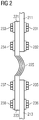
- FIG. 2 shows a detailed view of two interconnected busbars 211, 213 according to an exemplary embodiment of the invention.
- the busbar 211 is coupled to electrical connector 221 by two bolts 231, 232 and two nuts 233, 234.
- the busbar 213 is coupled to electrical connector 223 by two bolts 235, 236 and two nuts 237, 238.
- the electrical connectors 221, 223 are connected through a flex cable 225.
- the interconnection principle shown in Figure 2 can be used to interconnect two busbars, as shown, but also to interconnect a busbar and a generator winding (not shown) or a busbar and an output power cable (or busbar).
- the connections using bolts and nuts are easy to use as long as there is enough room for the needed tools (see above). Furthermore, the connections are generally very effective and reliable.
- FIG 3 shows a segment 300 of a stator with an arrangement of windings 310, 320, 330 in a so called "distributed winding" scheme.
- Each winding 310, 320, 330 is shown as a metal strip folded to give a closed loop.
- Three distinct winding types W1, W2, W3 are shown.
- Each coil comprises a sequence of windings 310, 320, 330, whereby a coil sequence comprises each of the different winding types W1, W2, W3 in turn.
- the respective bus bar arrangements for connecting the windings 310, 320, 330 to output power electronics are shown in figures 1 and 2 and discussed above.
- FIG 4 shows a segment 400 of a stator with an exemplary winding 401 in stator slots 403 of a stator lamination 404 in a so called "concentrated winding" scheme.
- two copper bars 405 of one winding 401 are located in adjacent stator slots 403.
- two adjacent slots 403 are shown in which a winding is locatable.
- the respective bus bar arrangements for connecting the winding 401 to output power electronics are shown in figures 1 and 2 and discussed above.
- FIG. 5 shows a very simplified representation of a generator 4 in a wind turbine 5.
- a generator 4 in a wind turbine 5.
- Pressure exerted on the blades 50 of the wind turbine 5 causes the hub 51 or spinner to turn, thus causing a rotor 3 to rotate.
- the rotor 3 is enclosed in a stator 2, about which a plurality of coils (not shown in the diagram) is wound.
- the generator 4 operates as an induction motor, with a current being induced in the coils. The principle of operation of such a generator will be clear to the skilled person and need not be described in detail here.
- the windings must be correspondingly dimensioned.
- the windings are typically made of stacked metal bars or strips with a cross-section in the region of 20 mm x 100 mm. These metal strips are held in stator slots arranged around the outside of the stator, which can be up to 3 m in length.
- the stator generally comprises a set of stator segments, e.g. configured as shown in figures 3 and 4 .
- the windings of the stator 2 are connected to a compact busbar arrangement 100 as shown in figures 1 and 2 and discussed above.
- the busbar arrangement is located on the side of the generator 4 that is opposite to the blades 50 and hub 51.
Landscapes
- Engineering & Computer Science (AREA)
- Life Sciences & Earth Sciences (AREA)
- Sustainable Development (AREA)
- Sustainable Energy (AREA)
- Chemical & Material Sciences (AREA)
- Combustion & Propulsion (AREA)
- Mechanical Engineering (AREA)
- General Engineering & Computer Science (AREA)
- Power Engineering (AREA)
- Wind Motors (AREA)
- Windings For Motors And Generators (AREA)
Abstract
Description
- The present invention relates to the field of wind turbine generators, in particular to a busbar arrangement for a wind turbine generator, a wind turbine generator comprising such a busbar arrangement, and a method of manufacturing a wind turbine.
- In a wind turbine, the horizontal distance from the center of gravity of the blade rotor to the tower is important for the gravity load on the main structure. This means that for a wind turbine with a generator between the blade rotor and the tower, the length of the generator is important. The total length of the generator can be seen as the sum of the lengths of an active and a passive generator part, where the active generator part is formed of magnets and windings while the passive generator part is formed of support structure and electrical connections (such as busbars) for transporting the produced electrical power away from the generator, e.g. to a power converter located at ground level.
- Accordingly, there may be a need for a way of maximizing the active length of magnets and windings and minimizing the passive length used for structure and electrical connections.
- This need may be met by the subject matter according to the independent claims. Advantageous embodiments of the present invention are set forth in the dependent claims.
- According to a first aspect of the invention, there is provided a busbar arrangement for a wind turbine generator, the wind turbine generator comprising a stator and a rotor arranged to rotate around an axis. The arrangement comprises a plurality of busbars for transporting electric power away from the generator, wherein each busbar is arranged at an individual radial distance from the axis and at an individual axial position along the axis.
- This aspect of the invention is based on the idea that by arranging the busbars with individual radial distances from the axis (e.g. as opposed to arranging the busbars at the same radial distance from the axis), a compact busbar arrangement can be obtained. In particular, the axial extension of the busbar arrangement (which contributes to the total length of the generator, in particular to the inactive part of the generator) can be reduced while still allowing easy access to each busbar during mounting and maintenance.
- According to an embodiment of the invention, the radial distances from the axis for two neighboring busbars differ by a predetermined radial amount.
- In other words, the difference in radial distance from the axis is the same (i.e. equal to the predetermined radial amount) for any two neighboring busbars in the arrangement.
- According to a further embodiment of the invention, the axial positions of two neighboring busbars are separated by a predetermined axial amount.
- In other words, the busbars are equally separated (by the predetermined axial amount) in the axial direction.
- According to a further embodiment of the invention, the busbar located at the axial position closest to the rotor has a minimum radial distance from the axis, and the radial distance increases for axial positions with increasing axial distance from the rotor.
- Thus, the busbar closest to the rotor, i.e. closest to the active part of the generator is also closest to the axis and the distance from the axis increases for each busbar in the axial direction away from the rotor, i.e. away from the active part of the generator.
- According to a further embodiment of the invention, the plurality of busbars form a staircase-like structure.
- According to a further embodiment of the invention, each busbar is shaped as an arc around the axis.
- The busbars may extend all way or partially around the axis. Each busbar preferably has a curvature that assures that the radial distance from the axis is the same at any position of the arc-shaped busbar.
- According to a further embodiment of the invention, each busbar has a rectangular cross section.
- According to a further embodiment of the invention, the longer side of the rectangular cross section extends in the radial direction relative to the axis.
- Thereby, the extension of each busbar is minimal in the axial direction.
- According to a further embodiment of the invention, each busbar comprises one or more coupling portions for providing electrical connections to other components of the wind turbine and/or to other busbars.
- In other words, the coupling portions serve to connect the busbars with other electrical components of the wind turbine and/or to interconnect the busbars.
- According to a further embodiment of the invention, the coupling portions are adapted for being coupled to electrical connectors by screws or bolts.
- According to a further embodiment of the invention, the difference in radial distance from the axis and the axial separation between neighboring busbars are selected to allow accessing the coupling portions with corresponding tools.
- In other words, the radial distance from the axis and the axial separation of the busbars are selected in such a way that sufficient place is available for accessing the coupling portions with the tools, in particular without interference from other busbars.
- According to a second aspect of the invention, there is provided a wind turbine comprising a generator having a stator and a rotor arranged to rotate around an axis and adapted to generate electrical power, and a busbar arrangement according to the first aspect or any of the above embodiments, the busbar arrangement being supported by the stator and coupled to the generator to transport the electrical power away from the generator.
- This aspect of the invention is based on essentially the same idea as the first aspect described above and provides a wind turbine with an optimized generator length.
- According to a third aspect of the invention, there is provided a method of manufacturing a wind turbine. The method comprises (a) providing a generator having a stator and a rotor arranged to rotate around an axis, and (b) providing a plurality of busbars for transporting electric power away from the generator, wherein each busbar is arranged at an individual radial distance from the axis and at an individual axial position along the axis.
- This aspect of the invention is based on essentially the same idea as the first and second aspects described above.
- It is noted that embodiments of the invention have been described with reference to different subject matters. In particular, some embodiments have been described with reference to method type claims whereas other embodiments have been described with reference to apparatus type claims. However, a person skilled in the art will gather from the above and the following description that, unless otherwise indicated, in addition to any combination of features belonging to one type of subject matter also any combination of features relating to different subject matters, in particular to combinations of features of the method type claims and features of the apparatus type claims, is part of the disclosure of this document.
- The aspects defined above and further aspects of the present invention are apparent from the examples of embodiments to be described hereinafter and are explained with reference to the examples of embodiments. The invention will be described in more detail hereinafter with reference to examples of embodiments. However, it is explicitly noted that the invention is not limited to the described exemplary embodiments.
-
-
Figure 1 shows a cross-sectional view of a busbar arrangement according to an exemplary embodiment of the invention. -
Figure 2 shows a detailed view of two interconnected busbars according to an exemplary embodiment of the invention. -
Figure 3 shows a stator segment which may be connected to a busbar arrangement according to an exemplary embodiment of the invention. -
Figure 4 shows another stator segment which may be connected to a busbar arrangement according to an exemplary embodiment of the invention. -
Figure 5 shows a schematic representation of a generator in a wind turbine. - The illustration in the drawing is schematic. It is noted that in different figures, similar or identical elements are provided with the same reference numerals or with reference numerals which differ only within the first digit.
-
Figure 1 shows a cross-sectional view of abusbar arrangement 100 according to an exemplary embodiment of the invention. The busbar arrangement comprisesbusbars busbar 110 is closest to the active part of a generator of a wind turbine (not shown), i.e. to the part of the generator that produces electric power when a rotor rotates about theaxis 105 and thereby generates electrical currents in a corresponding part of a stator. Theother busbars busbars axis 105. Eachbusbar axis 105. Furthermore, thebusbar 112 has a larger radial distance from theaxis 105 than thebusbar 110, thebusbar 114 has a larger radial distance from theaxis 105 than thebusbar 112, and thebusbar 116 has a larger radial distance from theaxis 105 than thebusbar 114. Thebusbars inclined support structure 120 and thus forms a staircase-like structure. Furthermore,electrical connectors busbars bolts -
Figure 1 also shows a set of tools for coupling theelectrical connector 122 to the corresponding coupling portion ofbusbar 112, more specifically anelectric screwdriver 140 with ahead 142fitting bolt 133, and a spanner orwrench 144fitting nut 132. It should be noted that thetools busbar arrangement 100 but used during mounting and maintenance work to connect thebusbars electrical connectors busbars busbars tools busbars axis 105, thebusbar 114 would have to be located on the opposite side ofscrewdriver 140 and thus even further away frombusbar 112 than the axial position ofbusbar 116 inFigure 1 . Accordingly, the shown busbar structure is significantly more compact than a simple horizontal arrangement which would be significantly longer in the direction ofaxis 105. Thereby, the busbar structure of the present invention allows easy mounting while minimizing the passive (i.e. non-active) length of the wind turbine generator and thereby minimizing the structural load on the wind turbine tower. -
Figure 2 shows a detailed view of twointerconnected busbars busbar 211 is coupled toelectrical connector 221 by twobolts nuts busbar 213 is coupled toelectrical connector 223 by twobolts nuts electrical connectors flex cable 225. The interconnection principle shown inFigure 2 can be used to interconnect two busbars, as shown, but also to interconnect a busbar and a generator winding (not shown) or a busbar and an output power cable (or busbar). The connections using bolts and nuts are easy to use as long as there is enough room for the needed tools (see above). Furthermore, the connections are generally very effective and reliable. -
Figure 3 shows asegment 300 of a stator with an arrangement ofwindings windings windings figures 1 and2 and discussed above. -
Figure 4 shows asegment 400 of a stator with an exemplary winding 401 instator slots 403 of astator lamination 404 in a so called "concentrated winding" scheme. In this configuration, twocopper bars 405 of one winding 401 are located inadjacent stator slots 403. As example of the position of adjacent "concentrated" windings, twoadjacent slots 403 are shown in which a winding is locatable. The respective bus bar arrangements for connecting the winding 401 to output power electronics are shown infigures 1 and2 and discussed above. -
Figure 5 shows a very simplified representation of agenerator 4 in awind turbine 5. For the sake of simplicity, only the relevant components are indicated, and other components such as a gearbox, controller, etc. are not shown. Pressure exerted on theblades 50 of thewind turbine 5 causes thehub 51 or spinner to turn, thus causing arotor 3 to rotate. Therotor 3 is enclosed in astator 2, about which a plurality of coils (not shown in the diagram) is wound. Thegenerator 4 operates as an induction motor, with a current being induced in the coils. The principle of operation of such a generator will be clear to the skilled person and need not be described in detail here. Because of the large currents (for example in the region of 200 - 500 Amps for 2 - 10 MW wind turbines), the windings must be correspondingly dimensioned. For a wind turbine stator, the windings are typically made of stacked metal bars or strips with a cross-section in the region of 20 mm x 100 mm. These metal strips are held in stator slots arranged around the outside of the stator, which can be up to 3 m in length. Generally, because of the large dimensions (a wind turbine stator can have a diameter in the region of 3 m to 7 m or more), the stator generally comprises a set of stator segments, e.g. configured as shown infigures 3 and4 . In order to transport produced electric power from thegenerator 4 to power electronics, such as rectifiers and power converters (not shown), the windings of thestator 2 are connected to acompact busbar arrangement 100 as shown infigures 1 and2 and discussed above. The busbar arrangement is located on the side of thegenerator 4 that is opposite to theblades 50 andhub 51. - It is noted that the term "comprising" does not exclude other elements or steps and the use of the articles "a" or "an" does not exclude a plurality. Also elements described in association with different embodiments may be combined. It is further noted that reference signs in the claims are not to be construed as limiting the scope of the claims.
Claims (13)
- A busbar arrangement (100) for a wind turbine generator, the wind turbine generator comprising a stator and a rotor arranged to rotate around an axis (105), the arrangement comprising
a plurality of busbars (110, 112, 114, 116) for transporting electric power away from the generator,
wherein each busbar is arranged at an individual radial distance from the axis and at an individual axial position along the axis. - The arrangement (100) according to the preceding claim, wherein the radial distances from the axis for two neighboring busbars differ by a predetermined radial amount.
- The arrangement (100) according to any of the preceding claims, wherein the axial positions of two neighboring busbars are separated by a predetermined axial amount.
- The arrangement (100) according to any of the preceding claims, wherein the busbar (110) located at the axial position closest to the rotor has a minimum radial distance from the axis, and wherein the radial distance increases for axial positions with increasing axial distance from the rotor.
- The arrangement according to any of the preceding claims, wherein the plurality of busbars form a staircase-like structure.
- The arrangement according to any of the preceding claims, wherein each busbar is shaped as an arc around the axis.
- The arrangement according to any of the preceding claims, wherein each busbar has a rectangular cross section.
- The arrangement according to the preceding claim, wherein the longer side of the rectangular cross section extends in the radial direction relative to the axis.
- The arrangement according to any of the preceding claims, wherein each busbar comprises one or more coupling portions for providing electrical connections to other components of the wind turbine or to other busbars.
- The arrangement according to the preceding claim, wherein the coupling portions are adapted for being coupled to electrical connectors (122, 124, 126, 221, 223) by screws or bolts (133, 135, 137, 233, 234, 237, 238).
- The arrangement according to claim 9 or 10, wherein the difference in radial distance from the axis and the axial separation between neighboring busbars are selected to allow accessing the coupling portions with corresponding tools (140, 144).
- A wind turbine comprising
a generator having a stator and a rotor arranged to rotate around an axis (105) and adapted to generate electrical power, and
a busbar arrangement (100) according to any of the preceding claims, the busbar arrangement being supported by the stator and coupled to the generator to transport the electrical power away from the generator. - A method of manufacturing a wind turbine, the method comprising
providing a generator having a stator and a rotor arranged to rotate around an axis (105), and
providing a plurality of busbars (110, 112, 114, 116) for transporting electric power away from the generator,
wherein each busbar is arranged at an individual radial distance from the axis and at an individual axial position along the axis.
Priority Applications (4)
| Application Number | Priority Date | Filing Date | Title |
|---|---|---|---|
| DK19200994.2T DK3800349T3 (en) | 2019-10-02 | 2019-10-02 | Busbar arrangement for a wind turbine generator |
| EP19200994.2A EP3800349B1 (en) | 2019-10-02 | 2019-10-02 | Busbar arrangement for wind turbine generator |
| CN202011042499.4A CN112600330B (en) | 2019-10-02 | 2020-09-28 | Bus bar arrangement for a wind turbine generator |
| US17/038,010 US11293412B2 (en) | 2019-10-02 | 2020-09-30 | Busbar arrangement for wind turbine generator |
Applications Claiming Priority (1)
| Application Number | Priority Date | Filing Date | Title |
|---|---|---|---|
| EP19200994.2A EP3800349B1 (en) | 2019-10-02 | 2019-10-02 | Busbar arrangement for wind turbine generator |
Publications (2)
| Publication Number | Publication Date |
|---|---|
| EP3800349A1 true EP3800349A1 (en) | 2021-04-07 |
| EP3800349B1 EP3800349B1 (en) | 2022-08-03 |
Family
ID=68136201
Family Applications (1)
| Application Number | Title | Priority Date | Filing Date |
|---|---|---|---|
| EP19200994.2A Active EP3800349B1 (en) | 2019-10-02 | 2019-10-02 | Busbar arrangement for wind turbine generator |
Country Status (4)
| Country | Link |
|---|---|
| US (1) | US11293412B2 (en) |
| EP (1) | EP3800349B1 (en) |
| CN (1) | CN112600330B (en) |
| DK (1) | DK3800349T3 (en) |
Cited By (2)
| Publication number | Priority date | Publication date | Assignee | Title |
|---|---|---|---|---|
| EP4297211A1 (en) | 2022-06-20 | 2023-12-27 | Siemens Gamesa Renewable Energy A/S | Adjustable busbar support |
| EP4429080A1 (en) | 2023-03-07 | 2024-09-11 | Siemens Gamesa Renewable Energy Innovation & Technology S.L. | Pre-assembled busbar module |
Citations (3)
| Publication number | Priority date | Publication date | Assignee | Title |
|---|---|---|---|---|
| US20140084590A1 (en) * | 2011-04-04 | 2014-03-27 | Columbia Power Technologies, Inc. | Mechanical assembly for maintaining an air gap between a stator and rotor in an electro-mechanical energy converter |
| US8847458B2 (en) * | 2011-02-28 | 2014-09-30 | Siemens Aktiengesellschaft | Electrical machine, in particular an electrical generator |
| CN208723499U (en) * | 2018-08-23 | 2019-04-09 | 中山市泰阳科慧实业有限公司 | A kind of wind power busbar insulation support device |
Family Cites Families (16)
| Publication number | Priority date | Publication date | Assignee | Title |
|---|---|---|---|---|
| FR2719718B1 (en) * | 1994-05-06 | 1996-06-07 | Schneider Electric Sa | Busbar device, in particular for an electrical distribution cabinet. |
| JP4649973B2 (en) * | 2004-12-14 | 2011-03-16 | 日産自動車株式会社 | Coil connection structure of axial gap type rotating electrical machine |
| DE102008018790A1 (en) * | 2008-04-15 | 2009-10-22 | Wobben, Aloys | Wind energy plant with busbars |
| JP2010044931A (en) * | 2008-08-12 | 2010-02-25 | Respect:Kk | Connection structure between electric appliances |
| JP2011160584A (en) * | 2010-02-02 | 2011-08-18 | Sugiyama Seisakusho:Kk | Insert molding method of terminal for rotary electric machine, terminal for rotary electric machine, and insert molding die of terminal for rotary electric machine |
| DE102010027498B4 (en) * | 2010-07-16 | 2012-08-23 | Flyteg Gmbh & Co. Kg | Method and device for repairing or replacing busbars on wind turbines |
| US8907517B2 (en) * | 2010-10-18 | 2014-12-09 | Vestas Wind Systems A/S | Wind turbine power transmission system |
| CN201877756U (en) * | 2010-11-25 | 2011-06-22 | 镇江西门子母线有限公司 | Cable incoming unit for wind power generation |
| EP2562915B1 (en) * | 2011-08-24 | 2015-05-20 | Sumitomo Wiring Systems, Ltd. | Central power supply member and method of assembling it |
| US9590468B2 (en) * | 2012-10-08 | 2017-03-07 | Exro Technologies Inc. | Electrical machines such as generators and motors |
| JP6155057B2 (en) * | 2013-03-08 | 2017-06-28 | Kyb株式会社 | Busbar unit manufacturing method and busbar unit |
| JP6286129B2 (en) * | 2013-03-08 | 2018-02-28 | Kyb株式会社 | Bus bar unit |
| CN104753017A (en) * | 2014-11-28 | 2015-07-01 | 樊纪保 | Electric power transmission equipment for wind tower |
| CN105958229B (en) * | 2016-04-27 | 2018-06-08 | 中车青岛四方车辆研究所有限公司 | Tiltedly go out the step-like terminal block of class |
| CN208723500U (en) * | 2018-08-23 | 2019-04-09 | 中山市泰阳科慧实业有限公司 | A lift-type special tubular busbar system for wind power |
| US11496018B2 (en) | 2019-01-10 | 2022-11-08 | Vestas Wind Systems A/S | Electrical generators in wind turbines |
-
2019
- 2019-10-02 EP EP19200994.2A patent/EP3800349B1/en active Active
- 2019-10-02 DK DK19200994.2T patent/DK3800349T3/en active
-
2020
- 2020-09-28 CN CN202011042499.4A patent/CN112600330B/en active Active
- 2020-09-30 US US17/038,010 patent/US11293412B2/en not_active Expired - Fee Related
Patent Citations (3)
| Publication number | Priority date | Publication date | Assignee | Title |
|---|---|---|---|---|
| US8847458B2 (en) * | 2011-02-28 | 2014-09-30 | Siemens Aktiengesellschaft | Electrical machine, in particular an electrical generator |
| US20140084590A1 (en) * | 2011-04-04 | 2014-03-27 | Columbia Power Technologies, Inc. | Mechanical assembly for maintaining an air gap between a stator and rotor in an electro-mechanical energy converter |
| CN208723499U (en) * | 2018-08-23 | 2019-04-09 | 中山市泰阳科慧实业有限公司 | A kind of wind power busbar insulation support device |
Cited By (4)
| Publication number | Priority date | Publication date | Assignee | Title |
|---|---|---|---|---|
| EP4297211A1 (en) | 2022-06-20 | 2023-12-27 | Siemens Gamesa Renewable Energy A/S | Adjustable busbar support |
| WO2023247079A1 (en) | 2022-06-20 | 2023-12-28 | Siemens Gamesa Renewable Energy A/S | Adjustable busbar support |
| EP4429080A1 (en) | 2023-03-07 | 2024-09-11 | Siemens Gamesa Renewable Energy Innovation & Technology S.L. | Pre-assembled busbar module |
| WO2024183940A1 (en) | 2023-03-07 | 2024-09-12 | Siemens Gamesa Renewable Energy Innovation & Technology S.L. | Pre-assembled busbar module |
Also Published As
| Publication number | Publication date |
|---|---|
| DK3800349T3 (en) | 2022-09-05 |
| EP3800349B1 (en) | 2022-08-03 |
| CN112600330B (en) | 2024-10-11 |
| CN112600330A (en) | 2021-04-02 |
| US20210102529A1 (en) | 2021-04-08 |
| US11293412B2 (en) | 2022-04-05 |
Similar Documents
| Publication | Publication Date | Title |
|---|---|---|
| US9306473B2 (en) | Variable rotor speed wind turbine, wind park, method of transmitting electric power and method of servicing or inspecting a variable rotor speed wind turbine | |
| US7863766B2 (en) | Power converter for use with wind generator | |
| US10886811B2 (en) | Segmented stator assembly with flexible electrical connections, generator and wind turbine with such a stator assembly | |
| US11293412B2 (en) | Busbar arrangement for wind turbine generator | |
| KR100456861B1 (en) | A wind power installation with a synchronous machine | |
| US20180102699A1 (en) | Segmented rotor for an asynchronous machine and an asynchronous machine having such a segmented rotor | |
| CN111919363A (en) | Combinations of AC motors and converter units and wind power plants | |
| EP3698455B1 (en) | Stator assembly with flexible cabling arrangements, generator and wind turbine with such a stator assembly | |
| US11962205B2 (en) | Mechanical strength of connection of wound rotor generator/motor | |
| CN115152129B (en) | Support structures and segmented stators for electric motors, wind turbines, and methods for manufacturing support structures. | |
| EP4142120A1 (en) | Winding connections for a generator of a wind turbine | |
| JPH0614502A (en) | Generator design and manufacturing method | |
| BR112016022144B1 (en) | METHOD OF PRODUCTION OF AN NULL ACTIVE PART OF AN ELECTRICAL MACHINE, RING SEGMENT FORMAT SECTION, ELECTRICAL MACHINE FOR A MILL IMPELLER, MILL AND SERVICE METHOD FOR AN ELECTRIC MACHINE | |
| US11959464B2 (en) | Wind turbine generators and methods for rotating a hub of a wind turbine | |
| US12456895B2 (en) | Retaining system with basic element and fixing elements to fix a bus bar on stator or stator segment of dynamoelectric machine | |
| EP3823138A1 (en) | Concentrated winding layout for a stator of an electrical ac machine | |
| US20210242740A1 (en) | Concentrated winding layout for a stator of an electrical ac machine | |
| CN114902538A (en) | Section of a generator for a wind turbine | |
| CN120642186A (en) | Stator for wind turbine generator, generator and wind turbine | |
| CN108512333B (en) | Modular stator and wind turbine generator set | |
| US20240396382A1 (en) | Winding assemblies and related methods | |
| EP4478587A1 (en) | Stator of an electrical machine | |
| EP4701045A1 (en) | Stator segment, electrical machine and wind turbine | |
| EP3550699B1 (en) | Winding design arrangement for an electrical machine and wind turbine generator | |
| CN115776187A (en) | Stator, motor and method for manufacturing stator |
Legal Events
| Date | Code | Title | Description |
|---|---|---|---|
| PUAI | Public reference made under article 153(3) epc to a published international application that has entered the european phase |
Free format text: ORIGINAL CODE: 0009012 |
|
| STAA | Information on the status of an ep patent application or granted ep patent |
Free format text: STATUS: THE APPLICATION HAS BEEN PUBLISHED |
|
| AK | Designated contracting states |
Kind code of ref document: A1 Designated state(s): AL AT BE BG CH CY CZ DE DK EE ES FI FR GB GR HR HU IE IS IT LI LT LU LV MC MK MT NL NO PL PT RO RS SE SI SK SM TR |
|
| AX | Request for extension of the european patent |
Extension state: BA ME |
|
| STAA | Information on the status of an ep patent application or granted ep patent |
Free format text: STATUS: REQUEST FOR EXAMINATION WAS MADE |
|
| 17P | Request for examination filed |
Effective date: 20210519 |
|
| RBV | Designated contracting states (corrected) |
Designated state(s): AL AT BE BG CH CY CZ DE DK EE ES FI FR GB GR HR HU IE IS IT LI LT LU LV MC MK MT NL NO PL PT RO RS SE SI SK SM TR |
|
| RIC1 | Information provided on ipc code assigned before grant |
Ipc: H02K 7/18 20060101ALN20220217BHEP Ipc: H02K 3/50 20060101ALI20220217BHEP Ipc: H02G 5/02 20060101ALI20220217BHEP Ipc: F03D 80/80 20160101AFI20220217BHEP |
|
| GRAP | Despatch of communication of intention to grant a patent |
Free format text: ORIGINAL CODE: EPIDOSNIGR1 |
|
| STAA | Information on the status of an ep patent application or granted ep patent |
Free format text: STATUS: GRANT OF PATENT IS INTENDED |
|
| RIC1 | Information provided on ipc code assigned before grant |
Ipc: H02K 7/18 20060101ALN20220303BHEP Ipc: H02K 3/50 20060101ALI20220303BHEP Ipc: H02G 5/02 20060101ALI20220303BHEP Ipc: F03D 80/80 20160101AFI20220303BHEP |
|
| INTG | Intention to grant announced |
Effective date: 20220325 |
|
| GRAS | Grant fee paid |
Free format text: ORIGINAL CODE: EPIDOSNIGR3 |
|
| GRAA | (expected) grant |
Free format text: ORIGINAL CODE: 0009210 |
|
| STAA | Information on the status of an ep patent application or granted ep patent |
Free format text: STATUS: THE PATENT HAS BEEN GRANTED |
|
| AK | Designated contracting states |
Kind code of ref document: B1 Designated state(s): AL AT BE BG CH CY CZ DE DK EE ES FI FR GB GR HR HU IE IS IT LI LT LU LV MC MK MT NL NO PL PT RO RS SE SI SK SM TR |
|
| REG | Reference to a national code |
Ref country code: AT Ref legal event code: REF Ref document number: 1508943 Country of ref document: AT Kind code of ref document: T Effective date: 20220815 Ref country code: CH Ref legal event code: EP |
|
| REG | Reference to a national code |
Ref country code: DE Ref legal event code: R096 Ref document number: 602019017705 Country of ref document: DE |
|
| REG | Reference to a national code |
Ref country code: IE Ref legal event code: FG4D |
|
| REG | Reference to a national code |
Ref country code: DK Ref legal event code: T3 Effective date: 20220829 |
|
| REG | Reference to a national code |
Ref country code: NL Ref legal event code: FP |
|
| REG | Reference to a national code |
Ref country code: LT Ref legal event code: MG9D |
|
| PG25 | Lapsed in a contracting state [announced via postgrant information from national office to epo] |
Ref country code: SE Free format text: LAPSE BECAUSE OF FAILURE TO SUBMIT A TRANSLATION OF THE DESCRIPTION OR TO PAY THE FEE WITHIN THE PRESCRIBED TIME-LIMIT Effective date: 20220803 Ref country code: RS Free format text: LAPSE BECAUSE OF FAILURE TO SUBMIT A TRANSLATION OF THE DESCRIPTION OR TO PAY THE FEE WITHIN THE PRESCRIBED TIME-LIMIT Effective date: 20220803 Ref country code: PT Free format text: LAPSE BECAUSE OF FAILURE TO SUBMIT A TRANSLATION OF THE DESCRIPTION OR TO PAY THE FEE WITHIN THE PRESCRIBED TIME-LIMIT Effective date: 20221205 Ref country code: NO Free format text: LAPSE BECAUSE OF FAILURE TO SUBMIT A TRANSLATION OF THE DESCRIPTION OR TO PAY THE FEE WITHIN THE PRESCRIBED TIME-LIMIT Effective date: 20221103 Ref country code: LV Free format text: LAPSE BECAUSE OF FAILURE TO SUBMIT A TRANSLATION OF THE DESCRIPTION OR TO PAY THE FEE WITHIN THE PRESCRIBED TIME-LIMIT Effective date: 20220803 Ref country code: LT Free format text: LAPSE BECAUSE OF FAILURE TO SUBMIT A TRANSLATION OF THE DESCRIPTION OR TO PAY THE FEE WITHIN THE PRESCRIBED TIME-LIMIT Effective date: 20220803 Ref country code: FI Free format text: LAPSE BECAUSE OF FAILURE TO SUBMIT A TRANSLATION OF THE DESCRIPTION OR TO PAY THE FEE WITHIN THE PRESCRIBED TIME-LIMIT Effective date: 20220803 Ref country code: ES Free format text: LAPSE BECAUSE OF FAILURE TO SUBMIT A TRANSLATION OF THE DESCRIPTION OR TO PAY THE FEE WITHIN THE PRESCRIBED TIME-LIMIT Effective date: 20220803 |
|
| REG | Reference to a national code |
Ref country code: AT Ref legal event code: MK05 Ref document number: 1508943 Country of ref document: AT Kind code of ref document: T Effective date: 20220803 |
|
| PG25 | Lapsed in a contracting state [announced via postgrant information from national office to epo] |
Ref country code: PL Free format text: LAPSE BECAUSE OF FAILURE TO SUBMIT A TRANSLATION OF THE DESCRIPTION OR TO PAY THE FEE WITHIN THE PRESCRIBED TIME-LIMIT Effective date: 20220803 Ref country code: IS Free format text: LAPSE BECAUSE OF FAILURE TO SUBMIT A TRANSLATION OF THE DESCRIPTION OR TO PAY THE FEE WITHIN THE PRESCRIBED TIME-LIMIT Effective date: 20221203 Ref country code: HR Free format text: LAPSE BECAUSE OF FAILURE TO SUBMIT A TRANSLATION OF THE DESCRIPTION OR TO PAY THE FEE WITHIN THE PRESCRIBED TIME-LIMIT Effective date: 20220803 Ref country code: GR Free format text: LAPSE BECAUSE OF FAILURE TO SUBMIT A TRANSLATION OF THE DESCRIPTION OR TO PAY THE FEE WITHIN THE PRESCRIBED TIME-LIMIT Effective date: 20221104 |
|
| PG25 | Lapsed in a contracting state [announced via postgrant information from national office to epo] |
Ref country code: SM Free format text: LAPSE BECAUSE OF FAILURE TO SUBMIT A TRANSLATION OF THE DESCRIPTION OR TO PAY THE FEE WITHIN THE PRESCRIBED TIME-LIMIT Effective date: 20220803 Ref country code: RO Free format text: LAPSE BECAUSE OF FAILURE TO SUBMIT A TRANSLATION OF THE DESCRIPTION OR TO PAY THE FEE WITHIN THE PRESCRIBED TIME-LIMIT Effective date: 20220803 Ref country code: CZ Free format text: LAPSE BECAUSE OF FAILURE TO SUBMIT A TRANSLATION OF THE DESCRIPTION OR TO PAY THE FEE WITHIN THE PRESCRIBED TIME-LIMIT Effective date: 20220803 Ref country code: AT Free format text: LAPSE BECAUSE OF FAILURE TO SUBMIT A TRANSLATION OF THE DESCRIPTION OR TO PAY THE FEE WITHIN THE PRESCRIBED TIME-LIMIT Effective date: 20220803 |
|
| REG | Reference to a national code |
Ref country code: DE Ref legal event code: R026 Ref document number: 602019017705 Country of ref document: DE |
|
| PLBI | Opposition filed |
Free format text: ORIGINAL CODE: 0009260 |
|
| PLAX | Notice of opposition and request to file observation + time limit sent |
Free format text: ORIGINAL CODE: EPIDOSNOBS2 |
|
| PG25 | Lapsed in a contracting state [announced via postgrant information from national office to epo] |
Ref country code: SK Free format text: LAPSE BECAUSE OF FAILURE TO SUBMIT A TRANSLATION OF THE DESCRIPTION OR TO PAY THE FEE WITHIN THE PRESCRIBED TIME-LIMIT Effective date: 20220803 Ref country code: MC Free format text: LAPSE BECAUSE OF FAILURE TO SUBMIT A TRANSLATION OF THE DESCRIPTION OR TO PAY THE FEE WITHIN THE PRESCRIBED TIME-LIMIT Effective date: 20220803 Ref country code: EE Free format text: LAPSE BECAUSE OF FAILURE TO SUBMIT A TRANSLATION OF THE DESCRIPTION OR TO PAY THE FEE WITHIN THE PRESCRIBED TIME-LIMIT Effective date: 20220803 |
|
| REG | Reference to a national code |
Ref country code: CH Ref legal event code: PL |
|
| 26 | Opposition filed |
Opponent name: WOBBEN PROPERTIES GMBH Effective date: 20230503 |
|
| REG | Reference to a national code |
Ref country code: BE Ref legal event code: MM Effective date: 20221031 |
|
| PG25 | Lapsed in a contracting state [announced via postgrant information from national office to epo] |
Ref country code: LU Free format text: LAPSE BECAUSE OF NON-PAYMENT OF DUE FEES Effective date: 20221002 Ref country code: AL Free format text: LAPSE BECAUSE OF FAILURE TO SUBMIT A TRANSLATION OF THE DESCRIPTION OR TO PAY THE FEE WITHIN THE PRESCRIBED TIME-LIMIT Effective date: 20220803 |
|
| P01 | Opt-out of the competence of the unified patent court (upc) registered |
Effective date: 20230530 |
|
| PG25 | Lapsed in a contracting state [announced via postgrant information from national office to epo] |
Ref country code: LI Free format text: LAPSE BECAUSE OF NON-PAYMENT OF DUE FEES Effective date: 20221031 Ref country code: CH Free format text: LAPSE BECAUSE OF NON-PAYMENT OF DUE FEES Effective date: 20221031 |
|
| PG25 | Lapsed in a contracting state [announced via postgrant information from national office to epo] |
Ref country code: SI Free format text: LAPSE BECAUSE OF FAILURE TO SUBMIT A TRANSLATION OF THE DESCRIPTION OR TO PAY THE FEE WITHIN THE PRESCRIBED TIME-LIMIT Effective date: 20220803 |
|
| PLBB | Reply of patent proprietor to notice(s) of opposition received |
Free format text: ORIGINAL CODE: EPIDOSNOBS3 |
|
| PG25 | Lapsed in a contracting state [announced via postgrant information from national office to epo] |
Ref country code: BE Free format text: LAPSE BECAUSE OF NON-PAYMENT OF DUE FEES Effective date: 20221031 |
|
| PG25 | Lapsed in a contracting state [announced via postgrant information from national office to epo] |
Ref country code: IE Free format text: LAPSE BECAUSE OF NON-PAYMENT OF DUE FEES Effective date: 20221002 |
|
| PG25 | Lapsed in a contracting state [announced via postgrant information from national office to epo] |
Ref country code: CY Free format text: LAPSE BECAUSE OF FAILURE TO SUBMIT A TRANSLATION OF THE DESCRIPTION OR TO PAY THE FEE WITHIN THE PRESCRIBED TIME-LIMIT Effective date: 20220803 |
|
| PG25 | Lapsed in a contracting state [announced via postgrant information from national office to epo] |
Ref country code: MK Free format text: LAPSE BECAUSE OF FAILURE TO SUBMIT A TRANSLATION OF THE DESCRIPTION OR TO PAY THE FEE WITHIN THE PRESCRIBED TIME-LIMIT Effective date: 20220803 Ref country code: IT Free format text: LAPSE BECAUSE OF FAILURE TO SUBMIT A TRANSLATION OF THE DESCRIPTION OR TO PAY THE FEE WITHIN THE PRESCRIBED TIME-LIMIT Effective date: 20220803 Ref country code: HU Free format text: LAPSE BECAUSE OF FAILURE TO SUBMIT A TRANSLATION OF THE DESCRIPTION OR TO PAY THE FEE WITHIN THE PRESCRIBED TIME-LIMIT; INVALID AB INITIO Effective date: 20191002 |
|
| PG25 | Lapsed in a contracting state [announced via postgrant information from national office to epo] |
Ref country code: BG Free format text: LAPSE BECAUSE OF FAILURE TO SUBMIT A TRANSLATION OF THE DESCRIPTION OR TO PAY THE FEE WITHIN THE PRESCRIBED TIME-LIMIT Effective date: 20220803 |
|
| PG25 | Lapsed in a contracting state [announced via postgrant information from national office to epo] |
Ref country code: MT Free format text: LAPSE BECAUSE OF FAILURE TO SUBMIT A TRANSLATION OF THE DESCRIPTION OR TO PAY THE FEE WITHIN THE PRESCRIBED TIME-LIMIT Effective date: 20220803 |
|
| APBP | Date of receipt of notice of appeal recorded |
Free format text: ORIGINAL CODE: EPIDOSNNOA2O |
|
| APAH | Appeal reference modified |
Free format text: ORIGINAL CODE: EPIDOSCREFNO |
|
| APAW | Appeal reference deleted |
Free format text: ORIGINAL CODE: EPIDOSDREFNO |
|
| APBM | Appeal reference recorded |
Free format text: ORIGINAL CODE: EPIDOSNREFNO |
|
| APBP | Date of receipt of notice of appeal recorded |
Free format text: ORIGINAL CODE: EPIDOSNNOA2O |
|
| APBQ | Date of receipt of statement of grounds of appeal recorded |
Free format text: ORIGINAL CODE: EPIDOSNNOA3O |
|
| APBQ | Date of receipt of statement of grounds of appeal recorded |
Free format text: ORIGINAL CODE: EPIDOSNNOA3O |
|
| APAH | Appeal reference modified |
Free format text: ORIGINAL CODE: EPIDOSCREFNO |
|
| PGFP | Annual fee paid to national office [announced via postgrant information from national office to epo] |
Ref country code: DK Payment date: 20250901 Year of fee payment: 7 |
|
| PGFP | Annual fee paid to national office [announced via postgrant information from national office to epo] |
Ref country code: GB Payment date: 20250901 Year of fee payment: 7 |
|
| PGFP | Annual fee paid to national office [announced via postgrant information from national office to epo] |
Ref country code: NL Payment date: 20251024 Year of fee payment: 7 |
|
| PG25 | Lapsed in a contracting state [announced via postgrant information from national office to epo] |
Ref country code: TR Free format text: LAPSE BECAUSE OF FAILURE TO SUBMIT A TRANSLATION OF THE DESCRIPTION OR TO PAY THE FEE WITHIN THE PRESCRIBED TIME-LIMIT Effective date: 20220803 |
|
| PGFP | Annual fee paid to national office [announced via postgrant information from national office to epo] |
Ref country code: DE Payment date: 20250829 Year of fee payment: 7 |
|
| PGFP | Annual fee paid to national office [announced via postgrant information from national office to epo] |
Ref country code: FR Payment date: 20251027 Year of fee payment: 7 |