EP3800160A1 - Liquid dispenser comprising a second reservoir and a receiver for a first reservoir - Google Patents
Liquid dispenser comprising a second reservoir and a receiver for a first reservoir Download PDFInfo
- Publication number
- EP3800160A1 EP3800160A1 EP19201579.0A EP19201579A EP3800160A1 EP 3800160 A1 EP3800160 A1 EP 3800160A1 EP 19201579 A EP19201579 A EP 19201579A EP 3800160 A1 EP3800160 A1 EP 3800160A1
- Authority
- EP
- European Patent Office
- Prior art keywords
- reservoir
- liquid
- receiver
- liquid dispenser
- release valve
- Prior art date
- Legal status (The legal status is an assumption and is not a legal conclusion. Google has not performed a legal analysis and makes no representation as to the accuracy of the status listed.)
- Granted
Links
Images




Classifications
-
- B—PERFORMING OPERATIONS; TRANSPORTING
- B67—OPENING, CLOSING OR CLEANING BOTTLES, JARS OR SIMILAR CONTAINERS; LIQUID HANDLING
- B67D—DISPENSING, DELIVERING OR TRANSFERRING LIQUIDS, NOT OTHERWISE PROVIDED FOR
- B67D3/00—Apparatus or devices for controlling flow of liquids under gravity from storage containers for dispensing purposes
- B67D3/0029—Apparatus or devices for controlling flow of liquids under gravity from storage containers for dispensing purposes provided with holders for bottles or similar containers
- B67D3/0035—Apparatus or devices for controlling flow of liquids under gravity from storage containers for dispensing purposes provided with holders for bottles or similar containers the bottle or container being held upside down and not provided with a closure, e.g. a bottle screwed onto a base of a dispenser
-
- B—PERFORMING OPERATIONS; TRANSPORTING
- B67—OPENING, CLOSING OR CLEANING BOTTLES, JARS OR SIMILAR CONTAINERS; LIQUID HANDLING
- B67D—DISPENSING, DELIVERING OR TRANSFERRING LIQUIDS, NOT OTHERWISE PROVIDED FOR
- B67D3/00—Apparatus or devices for controlling flow of liquids under gravity from storage containers for dispensing purposes
- B67D3/0038—Apparatus or devices for controlling flow of liquids under gravity from storage containers for dispensing purposes the liquid being stored in an intermediate container prior to dispensing
-
- B—PERFORMING OPERATIONS; TRANSPORTING
- B67—OPENING, CLOSING OR CLEANING BOTTLES, JARS OR SIMILAR CONTAINERS; LIQUID HANDLING
- B67D—DISPENSING, DELIVERING OR TRANSFERRING LIQUIDS, NOT OTHERWISE PROVIDED FOR
- B67D3/00—Apparatus or devices for controlling flow of liquids under gravity from storage containers for dispensing purposes
- B67D3/0041—Apparatus or devices for controlling flow of liquids under gravity from storage containers for dispensing purposes with provisions for metering the liquid to be dispensed
- B67D3/0045—Apparatus or devices for controlling flow of liquids under gravity from storage containers for dispensing purposes with provisions for metering the liquid to be dispensed by filling a predetermined volume before dispensing
-
- B—PERFORMING OPERATIONS; TRANSPORTING
- B67—OPENING, CLOSING OR CLEANING BOTTLES, JARS OR SIMILAR CONTAINERS; LIQUID HANDLING
- B67D—DISPENSING, DELIVERING OR TRANSFERRING LIQUIDS, NOT OTHERWISE PROVIDED FOR
- B67D3/00—Apparatus or devices for controlling flow of liquids under gravity from storage containers for dispensing purposes
- B67D3/0058—Details
- B67D3/0061—Details of liquid containers, e.g. filling, emptying, closing or opening means
- B67D3/007—Details of liquid containers, e.g. filling, emptying, closing or opening means containers with adjustable volume
-
- B—PERFORMING OPERATIONS; TRANSPORTING
- B67—OPENING, CLOSING OR CLEANING BOTTLES, JARS OR SIMILAR CONTAINERS; LIQUID HANDLING
- B67D—DISPENSING, DELIVERING OR TRANSFERRING LIQUIDS, NOT OTHERWISE PROVIDED FOR
- B67D3/00—Apparatus or devices for controlling flow of liquids under gravity from storage containers for dispensing purposes
- B67D3/04—Liquid-dispensing taps or cocks adapted to seal and open tapping holes of casks, e.g. for beer
- B67D3/043—Liquid-dispensing taps or cocks adapted to seal and open tapping holes of casks, e.g. for beer with a closing element having a linear movement, in a direction perpendicular to the seat
Definitions
- the present invention belongs to the field of liquid dispensers.
- Liquid dispensers typically comprise a liquid reservoir and a release valve through which the liquid is selectively released from the liquid reservoir out of the liquid dispenser.
- Liquid dispensers normally comprise an actuator which can be actuated to open and/or close the release valve so as to release a certain amount of liquid during a given period of time.
- the control of the volume of liquid which is released out of the liquid dispenser might need for the provision of a dedicated system in the liquid dispenser, such as an electronic system, which may lead to more expensive and difficult to maintain liquid dispensers.
- a liquid dispenser comprising:
- the liquid dispenser comprises a receiver for receiving a first reservoir.
- the receiver is advantageous in that it can be configured to receive different first reservoirs, thus allowing for multiple uses of the liquid dispenser.
- the liquid dispenser comprises a second reservoir.
- the liquid contained in a first reservoir can flow to the second reservoir through a fluid passageway when the first reservoir is received in the receiver.
- the second reservoir may be filled with liquid from the first reservoir until the volume of the second reservoir is filled with the liquid. Such volume of liquid may be released out of the liquid dispenser through a release valve.
- the liquid dispenser of the present invention may advantageously release a predetermined volume of liquid, which can be chosen by choosing the volume of the second reservoir. Such determination of the released amount of liquid is independent from the type and volume of the first reservoir, which may be externally provided to the user or operator of the liquid dispenser. Likewise, the liquid dispenser might not require complex dedicated components to determine the volume of the released liquid, such as electronic components or sensors which may be expensive to operate and maintain.
- the provision of a second reservoir which is provided between the receiver and the release valve may also be beneficial to prevent the liquid contained in the first reservoir from dripping out of the liquid dispenser during reception or removal of the first reservoir in the receiver.
- volume of the second reservoir is construed as the volume defined by the elements which constitute the internal walls of the second reservoir minus the volume occupied by any non-permeable component disposed at the interior of the second reservoir.
- the receiver may comprise a receiver wall.
- the second reservoir may be defined by the receiver wall and a second reservoir housing.
- the liquid dispenser may comprise at least one movable part.
- the at least one movable part may be movable with respect to the second reservoir housing between a first position and a second position, such that the volume of the second reservoir varies from a first volume to a second volume different from the first volume.
- liquid dispenser may be easily and quickly adjustable to dispense different predetermined volumes of liquid.
- the liquid dispenser may be used for different applications which may require the release of different volumes of liquid.
- the at least one movable part may comprise a removable part such that, in a second position of the removable part, the removable part is disposed at the interior of the second reservoir, such that the second reservoir has a second volume; and, in a first position of the removable part, the removable part is removed from the interior of the second reservoir, such that the second reservoir has a first volume which is greater than the second volume.
- a removable part that can be arranged inside the second reservoir in a second position and outside the second reservoir in a first position provides for an efficient and simple manner of dispensing different predetermined volumes of liquid.
- the removable part may be a hollow fillable part.
- Such hollow fillable part may be configured to be filled with materials which are denser than the liquids that are intended to be contained in the second reservoir. This way, the removable part may be disposed at a bottom of the second reservoir and may remain at the bottom even when the second reservoir is filled with the liquid.
- the hollow fillable part is configured to be filled with sand.
- the liquid dispenser may comprise a detachable wall configured to enable the removal and insertion of the removable part from and into the second reservoir.
- the detachable wall is the receiver wall.
- the at least one movable part may comprise the receiver wall.
- the receiver wall may be movable with respect to the second reservoir housing between a first position and a second position, such that the volume of the second reservoir varies from a first volume to a second volume different from the first volume.
- the second reservoir is defined by the second reservoir housing and the receiver wall.
- the receiver wall is movable with respect to the second reservoir housing, which allows a variation of the volume of the second reservoir.
- liquid dispenser may be easily and quickly adjusted to dispense different predetermined volumes of liquid, without a need for any additional part dedicated to achieve the variation of volume.
- the liquid dispenser may be used for different applications which may require the release of different volumes of liquid while having a compact and simple design.
- the receiver wall may also be movable to a plurality of intermediate positions between the first position and the second position.
- the number and location of the intermediate positions may be selected depending on the predetermined volumes of liquid that may be intended to be dispensed.
- the at least one movable part comprises both the removable part and the receiver wall.
- This provides for more versatility in the adjustment of the volume of the second reservoir.
- the receiver wall may be configured to rotate with respect to the second reservoir housing between the first position and the second position.
- the receiver wall may be configured to move linearly with respect to the second reservoir housing between the first position and the second position.
- the receiver wall may be configured to rotate and to move linearly with respect to the second reservoir housing between the first position and the second position.
- Such combination of linear and rotational relative movement between the receiver wall and the second reservoir housing may be advantageous to allow for a quick and robust movement of the receiver wall between the first position and the second position.
- the second reservoir housing may comprise at least one helical slot and the receiver wall may comprise at least one stem configured to slide between a first point and a second point of the at least one helical slot, such that the receiver wall moves from the first position to the second position when the at least one stem slides from the first point to the second point.
- the at least one helical slot and the at least one stem may advantageously allow for the combination of linear and rotational relative movement between the receiver wall and the second reservoir housing.
- the at least one helical slot comprises three helical slots and the at least one stem comprises three stems, each of the three stems being configured to slide along a different helical slot.
- the first volume and the second volume may be comprised in a range from 20 millilitres to 600 millilitres, the first volume being greater than the second volume. In a preferred embodiment, the first and the second volume may be comprised in a range from 150 millilitres to 500 millilitres.
- liquid dispenser to release a volume of liquid between 20 millilitres and 600 millilitres, more preferably between 150 millilitres and 500 millilitres, when the release valve is in the open position.
- volumes of liquid may be adequate when the liquid is used for hygienic or cleaning purposes.
- the liquid dispenser may comprise a lock configured to lock the receiver wall in the first position and/or in the second position.
- the volume of the second reservoir can be set at the first volume and/or to the second volume. This may allow for the first volume and/or the second volume to be fixed before the liquid dispenser is used by an operator or a user, thus minimizing the risk of an incorrect volume of a certain liquid being applied.
- the lock may also be configured to lock the receiving wall in any intermediate positions that may be provided between the first position and the second position.
- the liquid dispenser may comprise an actuator configured to move the release valve from the closed position to the open position.
- the release valve is moved from the closed position to the open position when the second reservoir is filled with the liquid.
- the volume of liquid released though the release valve out of the liquid dispenser may correspond to the volume of the second reservoir.
- the actuator is configured to manually move the release valve from the closed position to the open position.
- the actuator may comprise a button.
- the button may be mechanically connected to the release valve by means of at least one arm such that, when the button is moved from a released position to a pressed position, the at least one arm moves the release valve from the closed position to the open position.
- Such arrangement may constitute a robust mechanism to enable the movement of the release valve from the closed position to the open position.
- the actuator may allow the release valve to be moved to the open position without requiring a considerable force by the user or operator, even when the volume of liquid to be released is above 20 millilitres, above 150 millilitres or above 500 millilitres.
- the actuator may comprise an electronic activator configured to be electronically programmed to move the button to the pressed position at a pre-set time or when the electronic activator receives an activating signal from an external device.
- the electronic activator comprises a solenoid.
- This embodiment permits to set up the release of liquid out of the liquid dispenser at predetermined times, without requiring the intervention of an operator or user.
- the electronic activator may be provided in an actuator not comprising a button.
- the electronic activator may be connected to the release valve by means of the at least one arm.
- the actuator may be configured to impede fluid communication through the fluid passageway when the release valve is in the open position.
- the release valve may release only the volume of liquid corresponding to the volume of the second reservoir when the release valve is moved to the open position after the second reservoir is filled with the liquid. This may guarantee that the precise amount of liquid required for a certain use is released.
- the fluid passageway and the release valve may be configured such that the time needed to fill in the second reservoir (that is, the fill time) is at least about 3 times greater than the time needed to release the whole volume of liquid contained in the second reservoir through the release valve (that is, the release time). Accordingly, even if the fluid passageway is open, the amount of liquid introduced into the second reservoir during the release time is significantly lower than the amount of liquid released during the release time. The liquid released during the release time may thus substantially correspond to the volume of the second reservoir.
- the release valve may comprise a buoyant element configured to float in the liquid contained in the second reservoir when the valve is in the open position and the second reservoir contains liquid.
- the buoyant element may be configured to move the release valve to the closed position when the second reservoir does not contain liquid.
- the release valve In the open position, the release valve is arranged in such a way that it allows for the flow of the liquid through a fluid aperture comprised in the release valve.
- the buoyant element may be arranged to impede the flow of liquid through the fluid aperture when the valve is in the closed position.
- the buoyant element may be configured such that, when the release valve is in the open position and the second reservoir contains liquid, the buoyant element floats in the liquid and therefore the buoyant element is away from the fluid aperture, so that the flow of liquid through the fluid aperture is allowed.
- the buoyant element When all the liquid is released from the second reservoir out of the liquid dispenser through the fluid aperture of the release valve, the buoyant element may be configured to return to the position in which it impedes the flow of liquid through the fluid aperture (for example, due to gravity and/or by means of an actuator), that is, to the closed position of the release valve.
- the buoyant element may comprise any suitable material which ensures that no flow of liquid is permitted through the fluid aperture when the release valve is in the closed position.
- the buoyant material comprises EPDM (Ethylene Propylene Diene Monomer).
- EPDM may be advantageous in that the resulting buoyant element is durable and sufficiently soft to provide for a reliable fluid seal.
- the buoyant element may be configured to float on the surface of the liquid contained in the second reservoir as soon as the buoyant element is completely surrounded by the liquid.
- the buoyant element may be configured to float partially or completely below the surface of the liquid contained in the second reservoir once the buoyant element is completely surrounded by the liquid.
- the release valve may comprise a magnetic seal configured to retain the release valve in the closed position.
- the magnetic seal may generate a magnetic force that retains (or contributes to retaining in cooperation with other forces) the release valve in the closed position.
- the magnetic seal comprises a magnet in a first part of the release valve and a ferrous element in a second part of the release valve.
- the magnetic seal may comprise the magnet in the second part and the ferrous element in the first part.
- the first part and the second part may be configured to move with respect to one another. When the release valve is in the closed position, the first part and the second part may be sufficiently close to one another such that the magnetic force helps retain the first part and the second part stationary with respect to one another.
- the first part and the second part may be disposed to impede the flow of liquid through the fluid aperture of the release valve when the release valve is in the closed position.
- a force exerted on the release valve (such as the force which, in an embodiment, exerts the actuator) should be greater than the magnetic force.
- the first part is the buoyant element and the second part is integral with the second reservoir housing.
- the first part or the second part may be configured to be retained in a position in which the first part or the second part block the flow of liquid through the fluid aperture by means of the hydrostatic pressure exerted by the liquid when the liquid is contained in the second reservoir.
- the receiver may comprise a one way valve configured to control the flow of liquid through the fluid passageway.
- the one way valve may be adequate to ensure that the liquid may only flow from the first reservoir to the second reservoir when the first reservoir is received in the receiver, that is, to impede the flow of liquid from the second reservoir to the first reservoir. This may enhance the accuracy of the volume of liquid released from the second reservoir out of the liquid dispenser.
- the one way valve may be configured to open to allow fluid communication between the first reservoir and the second reservoir by arranging the first reservoir in the receiver.
- This may be a quick and efficient manner to start the flow of liquid from the first reservoir to the second reservoir immediately after the first reservoir is received in the receiver, without a need for a specific actuation on the one way valve. Since the release of liquid out of the liquid dispenser is controlled by the release valve, specific actuation on the one way valve is not necessary to control the release of liquid out of the liquid dispenser. Besides, by immediately starting the flow of liquid from the first reservoir to the second reservoir when the first reservoir is received in the receiver, it may be ensured that the second reservoir is filled in after a period of time corresponding to the fill time from the reception of the first reservoir in the receiver.
- the liquid dispenser may comprise an electronic controller.
- the electronic controller may be configured to gather and display data regarding the use of the liquid dispenser.
- the liquid dispenser may comprise an electronic display configured to display the data gathered by the electronic controller.
- the electronic controller may be useful to inform the operator or user about parameters such as the fill time, the release time, the type of first reservoir received in the first reservoir, the volume of liquid released in each release out of the liquid dispenser, the number of liquid releases performed by the liquid dispenser within a given period or with the same first reservoir, among others.
- the electronic controller may be advantageously configured to operate the electronic activator.
- the liquid dispenser may comprise a power supply.
- the power supply may be configured to supply electric current to the electronic controller.
- the power supply may be configured to supply electric current to the electronic display.
- the power supply may also be configured to supply electric current to the electronic activator.
- the power supply may comprise a battery, such as a rechargeable battery.
- a liquid assembly comprising any of the above described liquid dispensers and a first reservoir received in the receiver.
- the liquid assembly of this disclosure may be advantageous for the same reasons as detailed above for the liquid dispensers.
- the first reservoir may comprise a first engagement element and the receiver may comprise a second engagement element complementary to the first engagement element, such that the first engagement element and the second engagement element are configured to fit one another when the first reservoir is received in the receiver.
- the first reservoir may comprise a cap having a first shape.
- the first shape may be the first engagement element.
- the receiver may comprise a one way valve having a second shape.
- the second shape may be the second engagement element. The first shape and the second shape may fit each other when the first reservoir is received in the receiver.
- first engagement element and the second engagement element respectively in components of the first reservoir and the receiver that also have other functions. Therefore, the advantages relative to the first engagement element and the second engagement element may be achieved without falling back on a more complex first reservoir or receiver.
- a method to release a liquid from a liquid dispenser comprising the steps of:
- the method of this disclosure may be advantageous for the same reasons as detailed above for the liquid dispensers.
- the at least one movable part comprises a removable part. In an embodiment, the at least one movable part comprises a receiver wall in turn comprised in the receiver. In an embodiment, the at least one movable part comprises the removable part and the receiver wall.
- the fill time may be at least about 3 times greater than the release time.
- a liquid assembly kit may comprise a plurality of liquid assemblies, each comprising a first reservoir and a liquid dispenser.
- the liquid assembly kit may comprise a retaining frame in which the liquid assemblies are received, for example by snap fitting.
- the liquid assembly kit may be beneficial to easily carry and provide a plurality of liquid assemblies.
- a liquid dispenser unit may comprise a liquid assembly kit and a structure in which the liquid assembly kit is received.
- the structure may comprise a frame receiver which may be helpful to receive the retaining frame of the liquid assembly kit when the liquid assembly kit comprises such retaining frame.
- the structure may be a fixed structure, such as a panel fixedly disposed in the premises of an operator or user.
- the liquid dispenser unit comprising a fixed structure may be advantageously arranged such that the liquid assemblies are capable of releasing liquid onto a given external structure or device, such as an external cleaning structure or cleaning device.
- the volume of the second reservoir of each liquid dispenser in the liquid dispenser unit may be chosen such that the appropriate volume of liquid is released through the release valve of the liquid dispenser.
- the volume may be chosen in function of the type of liquid of the first reservoir that is assembled with each liquid dispenser in each liquid assembly.
- the volume may be chosen in function of the intended use of the liquid dispenser unit.
- FIG. 1 illustrates a liquid dispenser 1.
- the liquid dispenser 1 comprises a receiver 2, in turn comprising a receiver wall 21 and a fluid passageway 22.
- the receiver 2 is configured to receive a first reservoir, which is not represented in figure 1 .
- a second reservoir 3 is defined by the receiver wall 21 and a second reservoir housing 6.
- the second reservoir 3 comprises a release valve 4 which, in figure 1 , is arranged in a closed position.
- the fluid passageway 22 is configured to allow fluid communication between the first reservoir and the second reservoir 3, when the first reservoir is received in the receiver 2.
- the release valve 4 is configured to allow the release of liquid from the second reservoir 3 out of the liquid dispenser 1 when the release valve 4 is arranged in an open position and to retain liquid within the second reservoir 3 when the release valve 4 is in the closed position, as shown in figure 1 .
- the receiver wall 21 of the embodiment of figure 1 is movable with respect to the second reservoir housing 6.
- the second reservoir housing 6 comprises a helical slot 61 and the receiver wall 21 comprises a stem 23 configured to slide between a first point 62 of the helical slot 61 and a second point 63 of the helical slot 61, at which the stem 23 is arranged in figure 1 .
- the receiver wall 21 is in a second position such that the volume of the second reservoir 3, defined by the receiver wall 21 and the second reservoir housing 6, is a second volume.
- the stem 23 can slide along the helical slot 61 from the second point 63 to the first point 62, so that the receiver wall 21 rotates and moves linearly with respect to the second reservoir housing 6 to a first position.
- FIG. 6 shows a view from the outside of the liquid dispenser 1 of the helical slot 61 and the stem 22 when the receiver wall 21 is in the second position, that is, when the stem 23 is at the second point 63.
- the liquid dispenser comprises a lock 7 which, in figure 1 , locks the receiver wall 21 in the second position.
- the stem 23 may also be disposed at intermediate points between the first point 62 and the second point 63 of the helical slot 61, such that the receiver wall 21 is arranged at intermediate positions between the first position and the second position.
- intermediate volumes of the second reservoir 3, between the first volume and the second volume may be defined.
- the lock 7 may lock the receiver wall 21 at any intermediate position.
- the liquid dispenser 1 comprises an actuator 8 configured to move the release valve 4 from the closed position, represented in figure 1 , to the open position.
- the actuator 8 of figure 1 comprises a button 81 in a released position.
- the button 81 is mechanically connected to the release valve 4 by means of a first arm 82, a second arm 83 and a third arm 86 such that, when the button 81 is moved from the released position to a pressed position, the first arm 82, the second arm 83 and the third arm 86 move the release valve 4 from the closed to the open position.
- the actuator 8 In order to move the button 81 from the released position to the pressed position, the actuator 8 comprises a longitudinal shaft 84 integral with the button and configured to move longitudinally when the button is pressed or released.
- a spring 85 is provided to calibrate the force that needs to be applied to move the button 81 from the released position to the pressed position.
- the release valve 4 comprises a buoyant element 41.
- the buoyant element 41 is arranged to impede the flow of liquid through a fluid aperture 42 of the release valve 4 in the closed position represented in figure 4 .
- the release valve 4 of figure 1 comprises a magnetic seal which helps retain the release valve 4 in the closed position.
- the magnetic seal comprises a magnet 44 arranged integrally with the fluid aperture 42 and a ferrous element 43 which is integral with the buoyant element 41.
- the buoyant element 41 is sufficiently close to the fluid aperture 42 such that the magnetic force generated by the ferrous element 43 and the magnet 44 retains the buoyant element 41 in the position in which it impedes the flow of liquid through the fluid aperture 42, that is, in the closed position of the release valve 4.
- the release valve 4 of figure 1 comprises EPDM.
- the force exerted by the actuator 8 when the button 81 is pressed should be greater than the magnetic force generated by the magnet 44 and the ferrous element 43.
- Figure 2 depicts an embodiment of the liquid dispenser 1.
- the liquid dispenser 1 of figure 2 comprises a removable part 9.
- the removable part 9 is disposed at the interior of the second reservoir 3, that is, in a second position of the removable part 9, such that the second reservoir 3 has a second volume.
- the removable part 9 may be removed from the interior of the second reservoir 3, that is, the removable part 9 may be moved to a first position.
- the second reservoir 3 has a first volume which is greater than the second volume in a volume that corresponds to the volume of the removable part 9.
- the receiver wall 21 of the embodiment of figure 2 is similar to that of figure 1 , that is, movable between the first position and the second position. In figure 2 , the receiver wall is locked at the first position. However, in an example, the receiver wall 21 may be configured to be fixed at a fixed position, such that the adjustment of the volume of the second reservoir 3 is exclusively achieved by means of the removable part 9.
- the actuator 8 comprises an electronic activator 88 configured to be electronically programmed to move the button 81 to the pressed position at pre-set times or when the electronic activator 88 receives an activating signal from an external device.
- the electronic activator of figure 2 comprises a solenoid 89.
- the liquid dispenser 1 of figure 2 comprises an electronic controller 40.
- the electronic controller 40 gathers data regarding the use of the liquid dispenser 1, such as the fill time, the release time, the type of first reservoir 10 received in the receiver 2, the volume of liquid released in each release out of the liquid dispenser 1 and the number of liquid releases performed by the liquid dispenser 1 within a given period or with the same first reservoir 10.
- the liquid dispenser 1 of figure 2 comprises an electronic display 41 configured to display the data gathered by the electronic controller 40.
- the electronic controller 40 of figure 2 is also configured to operate the electronic activator 88.
- the liquid dispenser 1 comprises a battery 42 configured to supply electric current to the electronic controller 40, the electronic display 41 and the electronic activator 88.
- Figure 3 represents a liquid assembly 100 comprising the liquid dispenser 1 of figure 1 and a first reservoir 10 received in the receiver.
- the first reservoir 10 comprises a cap 11 having a first shape, which constitutes a first engagement element
- the receiver 2 comprises a one way valve 24 having a second shape, which forms a second engagement element.
- the first shape and the second shape fit each other when the first reservoir 10 is received in the receiver 2, as shown in figure 3 . This may be advantageous to ensure that the correct first reservoir 10 is received in the receiver 2.
- the one way valve 24 is provided in the receiver 2 to control the flow of liquid from the first reservoir 10 to the second reservoir 3 though the fluid passageway 22.
- the one way valve 24 opens to allow fluid communication between the first reservoir 10 and the second reservoir 3.
- the cap 11 exerts a pressure on the one way valve 24 such that a spring 241 of the one way valve 24 is compressed, thus allowing for the flow of liquid 200 through the fluid passageway 22.
- Liquid 200 flows to the second reservoir 3 during a fill time until the second reservoir 3 is filled with a volume of liquid defined by the second reservoir housing 6 and the receiver wall 21, which in the embodiment of figure 3 is in the second position, as explained for figure 1 .
- the release valve 4 is in the closed position.
- the hydrostatic pressure exerted by the liquid 200 on the buoyant element 41 contributes to maintaining the release valve 4 in the closed position, in addition to the magnetic force explained above.
- the magnetic force is sufficient to keep the release valve 4 in the closed position.
- the button 81 is in the released position during the fill time.
- the second reservoir 3 may be at least partially transparent or semi-transparent, so the operator or user can see when the second reservoir 3 is filled with the liquid 200.
- a counter may be provided so that the user or operator can determine when the fill time has lapsed.
- a sensor or indicator may be provided to detect and display when the second reservoir 3 is filled with the liquid 200.
- the liquid dispenser 1 comprises an electronic controller 40, as in the embodiment of figure 2 , the electronic controller 40 may comprise the counter.
- the electronic controller 40 may also comprise the sensor or indicator.
- the electronic display 41 may display a message to indicate the fill time has lapsed.
- Figure 4 illustrates the liquid assembly 100 of figure 3 at an instant in which the liquid 200 which filled the second reservoir 3 after the fill time is being released out of the liquid dispenser 1 though the released valve 4.
- the button 81 was moved to a pressed position in which the spring 85 is compressed and the longitudinal shaft 84 moves longitudinally to actuate on the third arm 86.
- the third arm 86 is articulated to the second arm 83 which is in turn articulated to the first arm 82.
- the first and 82 is integrally attached to the buoyant element 41 on one end and attached to the second reservoir housing 6 on an opposite end by means of a hinge 831.
- the hinge 831 permits a rotation of the first arm 82 with respect to the second reservoir housing 6. Such rotation causes a displacement of the buoyant element 41 when the second arm 83 is actuated by the third arm 86, the longitudinal shaft 84 and the button 81.
- the force exerted by the components of the actuator 8 overcomes the hydrostatic pressure and the magnetic force that kept the release valve 4 in the closed position.
- the buoyant element 41 In the open position represented in figure 4 , the buoyant element 41 floats in the liquid 200 and therefore the buoyant element 41 is away from the fluid aperture 42, so that the flow of liquid 200 through the fluid aperture 42 is allowed.
- the fluid aperture 42 and the other components of the release valve 4 are configured such that the liquid 200 is released from the second reservoir 3 out of the liquid dispenser 1 in a given release time.
- the fluid passageway 22 and the one way valve 24 may be configured to calibrate the fill time.
- the fill time is at least about 3 times greater than the release time, so that, even if the fluid passageway 22 is open, the amount of liquid 200 introduced into the second reservoir 3 during the release time is significantly lower than the amount of liquid released during the release time.
- a fourth arm (not represented) may be provided in the actuator 8 such that, when the button 81 is in the pressed position, the fourth arm blocks the fluid passageway 22. This way, no liquid is introduced into the second reservoir 3 during the release time, thus enhancing the accuracy of the released amount of liquid out of the liquid dispenser 1.
- the button 81 moves back to the released position and the first 82, second 83 and third 86 arms move the buoyant element 41 back to the position in which it blocks the flow of liquid through the fluid aperture 42, such that the release valve 4 is arranged in the closed position shown in figures 1 and 3 .
- the magnetic force of the ferrous element 43 and the magnet 44 intervenes to ensure the release valve 4 is retained in the closed position.
- the second reservoir 3 is then ready to be filled in again with liquid from a first reservoir, which can be the same as or different to the first reservoir used for the previous charge.
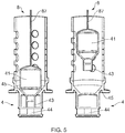
- the liquid dispenser 1 of this embodiment comprises an actuator 8 which comprises a bar 87.
- the bar 87 extends from the buoyant element 41 out of the liquid dispenser 1 such that, by pulling the bar 87, the buoyant element 41 is moved away from the fluid aperture 42 as shown in figure 5(B) .
- the release valve 4 of this embodiment comprises a tapered wall 45 which helps the buoyant element 41 return to the position in which it blocks the flow of liquid though the fluid aperture 42 when all the liquid contained in the second reservoir 3 is released out of the liquid dispenser 1.
- Figure 7 shows a liquid assembly kit 300 comprising three liquid dispensers 1 with their corresponding first reservoirs 10, thus forming three liquid assemblies 100.
- the liquid assemblies 100 snap fit in a retaining frame 30.
- the liquid assembly kit 300 enables that a plurality of liquid dispensers 1 may be easily incorporated into a liquid dispenser unit in which one or more liquids are needed, typically for hygienic or cleaning purposes.
- Figure 8 illustrates a liquid dispenser unit 600.
- the unit 600 comprises the liquid assembly kit 300 of figure 7 and a structure 400.
- the structure 400 comprises a frame receiver 401 in which the retaining frame 30 of the liquid assembly kit 300 can be arranged, as shown in figure 8 .
- the structure 400 comprises a base 403 and vertical supports 402 which join the frame receiver 401 to the base 403.
- the structure 400 of figure 8 is arranged such that the liquid assemblies 100 of the liquid assembly kit 300 are capable of releasing liquid onto a sink 500 arranged on the base 403.
- the liquid dispenser unit 600 may be advantageously used in combination with a cleaning article.
- the receiver wall 21 and/or the removable part 9 of each liquid dispenser 1 can be adjusted so that the volume of the second reservoir 3 of each liquid dispenser 1 has the adequate volume, which corresponds to the volume of liquid that is set to be released through the release valve 4 of the liquid dispenser 1.
- the chosen volume of liquid is released by pressing the button 81 as shown in the preceding figures.
Landscapes
- Engineering & Computer Science (AREA)
- Mechanical Engineering (AREA)
- Containers And Packaging Bodies Having A Special Means To Remove Contents (AREA)
Abstract
Description
- The present invention belongs to the field of liquid dispensers.
- Liquid dispensers typically comprise a liquid reservoir and a release valve through which the liquid is selectively released from the liquid reservoir out of the liquid dispenser. Liquid dispensers normally comprise an actuator which can be actuated to open and/or close the release valve so as to release a certain amount of liquid during a given period of time. However, the control of the volume of liquid which is released out of the liquid dispenser might need for the provision of a dedicated system in the liquid dispenser, such as an electronic system, which may lead to more expensive and difficult to maintain liquid dispensers. Likewise, it might not be possible to accurately control the volume of liquid that is released.
- It is therefore desirable to provide a liquid dispenser that may overcome at least some of these disadvantages.
- In a disclosure of the invention, a liquid dispenser is provided. The liquid dispenser comprises:
- a receiver for receiving a first reservoir, the receiver comprising a fluid passageway;
- a second reservoir comprising a release valve which can be arranged in an open position and in a closed position;
- wherein the fluid passageway is configured to allow fluid communication between the first reservoir and the second reservoir, when the first reservoir is received in the receiver; and,
- wherein the release valve is configured to allow the release of liquid from the second reservoir out of the liquid dispenser when the release valve is arranged in the open position.
- The liquid dispenser comprises a receiver for receiving a first reservoir. The receiver is advantageous in that it can be configured to receive different first reservoirs, thus allowing for multiple uses of the liquid dispenser.
- Likewise, the liquid dispenser comprises a second reservoir. The liquid contained in a first reservoir can flow to the second reservoir through a fluid passageway when the first reservoir is received in the receiver.
- The second reservoir may be filled with liquid from the first reservoir until the volume of the second reservoir is filled with the liquid. Such volume of liquid may be released out of the liquid dispenser through a release valve.
- Therefore, the liquid dispenser of the present invention may advantageously release a predetermined volume of liquid, which can be chosen by choosing the volume of the second reservoir. Such determination of the released amount of liquid is independent from the type and volume of the first reservoir, which may be externally provided to the user or operator of the liquid dispenser. Likewise, the liquid dispenser might not require complex dedicated components to determine the volume of the released liquid, such as electronic components or sensors which may be expensive to operate and maintain.
- The provision of a second reservoir which is provided between the receiver and the release valve may also be beneficial to prevent the liquid contained in the first reservoir from dripping out of the liquid dispenser during reception or removal of the first reservoir in the receiver.
- As used herein, "volume of the second reservoir" is construed as the volume defined by the elements which constitute the internal walls of the second reservoir minus the volume occupied by any non-permeable component disposed at the interior of the second reservoir.
- The receiver may comprise a receiver wall. The second reservoir may be defined by the receiver wall and a second reservoir housing.
- The liquid dispenser may comprise at least one movable part. The at least one movable part may be movable with respect to the second reservoir housing between a first position and a second position, such that the volume of the second reservoir varies from a first volume to a second volume different from the first volume.
- This may be advantageous in that a single liquid dispenser may be easily and quickly adjustable to dispense different predetermined volumes of liquid. Hence, the liquid dispenser may be used for different applications which may require the release of different volumes of liquid.
- The at least one movable part may comprise a removable part such that, in a second position of the removable part, the removable part is disposed at the interior of the second reservoir, such that the second reservoir has a second volume; and, in a first position of the removable part, the removable part is removed from the interior of the second reservoir, such that the second reservoir has a first volume which is greater than the second volume.
- The provision of a removable part that can be arranged inside the second reservoir in a second position and outside the second reservoir in a first position provides for an efficient and simple manner of dispensing different predetermined volumes of liquid.
- The removable part may be a hollow fillable part. Such hollow fillable part may be configured to be filled with materials which are denser than the liquids that are intended to be contained in the second reservoir. This way, the removable part may be disposed at a bottom of the second reservoir and may remain at the bottom even when the second reservoir is filled with the liquid. In an embodiment, the hollow fillable part is configured to be filled with sand.
- The liquid dispenser may comprise a detachable wall configured to enable the removal and insertion of the removable part from and into the second reservoir. In an embodiment, the detachable wall is the receiver wall.
- The at least one movable part may comprise the receiver wall. The receiver wall may be movable with respect to the second reservoir housing between a first position and a second position, such that the volume of the second reservoir varies from a first volume to a second volume different from the first volume.
- In this embodiment, the second reservoir is defined by the second reservoir housing and the receiver wall. The receiver wall is movable with respect to the second reservoir housing, which allows a variation of the volume of the second reservoir.
- This may be advantageous in that a single liquid dispenser may be easily and quickly adjusted to dispense different predetermined volumes of liquid, without a need for any additional part dedicated to achieve the variation of volume. Hence, the liquid dispenser may be used for different applications which may require the release of different volumes of liquid while having a compact and simple design.
- The receiver wall may also be movable to a plurality of intermediate positions between the first position and the second position. The number and location of the intermediate positions may be selected depending on the predetermined volumes of liquid that may be intended to be dispensed.
- In an embodiment, the at least one movable part comprises both the removable part and the receiver wall.
- This provides for more versatility in the adjustment of the volume of the second reservoir.
- The receiver wall may be configured to rotate with respect to the second reservoir housing between the first position and the second position. The receiver wall may be configured to move linearly with respect to the second reservoir housing between the first position and the second position. The receiver wall may be configured to rotate and to move linearly with respect to the second reservoir housing between the first position and the second position.
- Such combination of linear and rotational relative movement between the receiver wall and the second reservoir housing may be advantageous to allow for a quick and robust movement of the receiver wall between the first position and the second position.
- The second reservoir housing may comprise at least one helical slot and the receiver wall may comprise at least one stem configured to slide between a first point and a second point of the at least one helical slot, such that the receiver wall moves from the first position to the second position when the at least one stem slides from the first point to the second point.
- The at least one helical slot and the at least one stem may advantageously allow for the combination of linear and rotational relative movement between the receiver wall and the second reservoir housing.
- In an embodiment, the at least one helical slot comprises three helical slots and the at least one stem comprises three stems, each of the three stems being configured to slide along a different helical slot.
- The provision of three helical slots and three stems enhances the robustness of the liquid dispenser to withstand the relative movement between the receiver wall and the second reservoir housing.
- The first volume and the second volume may be comprised in a range from 20 millilitres to 600 millilitres, the first volume being greater than the second volume. In a preferred embodiment, the first and the second volume may be comprised in a range from 150 millilitres to 500 millilitres.
- This allows the liquid dispenser to release a volume of liquid between 20 millilitres and 600 millilitres, more preferably between 150 millilitres and 500 millilitres, when the release valve is in the open position. Such volumes of liquid may be adequate when the liquid is used for hygienic or cleaning purposes.
- The liquid dispenser may comprise a lock configured to lock the receiver wall in the first position and/or in the second position.
- Therefore, the volume of the second reservoir can be set at the first volume and/or to the second volume. This may allow for the first volume and/or the second volume to be fixed before the liquid dispenser is used by an operator or a user, thus minimizing the risk of an incorrect volume of a certain liquid being applied.
- The lock may also be configured to lock the receiving wall in any intermediate positions that may be provided between the first position and the second position.
- The liquid dispenser may comprise an actuator configured to move the release valve from the closed position to the open position.
- This may provide for an efficient manner of initiating the release of liquid from the second reservoir out of the liquid dispenser. Typically, the release valve is moved from the closed position to the open position when the second reservoir is filled with the liquid. Hence, the volume of liquid released though the release valve out of the liquid dispenser may correspond to the volume of the second reservoir.
- In an embodiment, the actuator is configured to manually move the release valve from the closed position to the open position.
- This may enable the operator or user to initiate the release of liquid from the second reservoir out of the liquid dispenser when they wish so.
- The actuator may comprise a button. The button may be mechanically connected to the release valve by means of at least one arm such that, when the button is moved from a released position to a pressed position, the at least one arm moves the release valve from the closed position to the open position.
- Such arrangement may constitute a robust mechanism to enable the movement of the release valve from the closed position to the open position. Likewise, the actuator may allow the release valve to be moved to the open position without requiring a considerable force by the user or operator, even when the volume of liquid to be released is above 20 millilitres, above 150 millilitres or above 500 millilitres.
- In an embodiment, the actuator may comprise an electronic activator configured to be electronically programmed to move the button to the pressed position at a pre-set time or when the electronic activator receives an activating signal from an external device. Preferably, the electronic activator comprises a solenoid.
- This embodiment permits to set up the release of liquid out of the liquid dispenser at predetermined times, without requiring the intervention of an operator or user.
- In an embodiment, the electronic activator may be provided in an actuator not comprising a button. In an example, the electronic activator may be connected to the release valve by means of the at least one arm.
- The actuator may be configured to impede fluid communication through the fluid passageway when the release valve is in the open position.
- This may be helpful to ensure that no liquid flows from the first reservoir to the second reservoir when the first reservoir is received in the receiver and the release valve is in the open position. Therefore, the release valve may release only the volume of liquid corresponding to the volume of the second reservoir when the release valve is moved to the open position after the second reservoir is filled with the liquid. This may guarantee that the precise amount of liquid required for a certain use is released.
- As an alternative or in addition to this embodiment, the fluid passageway and the release valve may be configured such that the time needed to fill in the second reservoir (that is, the fill time) is at least about 3 times greater than the time needed to release the whole volume of liquid contained in the second reservoir through the release valve (that is, the release time). Accordingly, even if the fluid passageway is open, the amount of liquid introduced into the second reservoir during the release time is significantly lower than the amount of liquid released during the release time. The liquid released during the release time may thus substantially correspond to the volume of the second reservoir.
- The release valve may comprise a buoyant element configured to float in the liquid contained in the second reservoir when the valve is in the open position and the second reservoir contains liquid. The buoyant element may be configured to move the release valve to the closed position when the second reservoir does not contain liquid.
- In the open position, the release valve is arranged in such a way that it allows for the flow of the liquid through a fluid aperture comprised in the release valve. The buoyant element may be arranged to impede the flow of liquid through the fluid aperture when the valve is in the closed position. Likewise, the buoyant element may be configured such that, when the release valve is in the open position and the second reservoir contains liquid, the buoyant element floats in the liquid and therefore the buoyant element is away from the fluid aperture, so that the flow of liquid through the fluid aperture is allowed. When all the liquid is released from the second reservoir out of the liquid dispenser through the fluid aperture of the release valve, the buoyant element may be configured to return to the position in which it impedes the flow of liquid through the fluid aperture (for example, due to gravity and/or by means of an actuator), that is, to the closed position of the release valve.
- The buoyant element may comprise any suitable material which ensures that no flow of liquid is permitted through the fluid aperture when the release valve is in the closed position. In an embodiment, the buoyant material comprises EPDM (Ethylene Propylene Diene Monomer).
- EPDM may be advantageous in that the resulting buoyant element is durable and sufficiently soft to provide for a reliable fluid seal.
- The buoyant element may be configured to float on the surface of the liquid contained in the second reservoir as soon as the buoyant element is completely surrounded by the liquid.
- This may allow for a reduction of the force exerted by the actuator, the button or any other suitable feature to open the release valve, since the buoyance force generated by the buoyant element soon after actuation to open the release valve helps moving the release valve to the open position.
- The buoyant element may be configured to float partially or completely below the surface of the liquid contained in the second reservoir once the buoyant element is completely surrounded by the liquid.
- The release valve may comprise a magnetic seal configured to retain the release valve in the closed position.
- The magnetic seal may generate a magnetic force that retains (or contributes to retaining in cooperation with other forces) the release valve in the closed position. In an embodiment, the magnetic seal comprises a magnet in a first part of the release valve and a ferrous element in a second part of the release valve. Similarly, the magnetic seal may comprise the magnet in the second part and the ferrous element in the first part. The first part and the second part may be configured to move with respect to one another. When the release valve is in the closed position, the first part and the second part may be sufficiently close to one another such that the magnetic force helps retain the first part and the second part stationary with respect to one another. The first part and the second part may be disposed to impede the flow of liquid through the fluid aperture of the release valve when the release valve is in the closed position. Therefore, the magnetic force retains the valve in the closed position. In this embodiment, in order to arrange the release valve from the closed position to the open position, a force exerted on the release valve (such as the force which, in an embodiment, exerts the actuator) should be greater than the magnetic force.
- In an example of this embodiment, the first part is the buoyant element and the second part is integral with the second reservoir housing.
- Alternatively or in addition to the provision of the magnetic seal, the first part or the second part may be configured to be retained in a position in which the first part or the second part block the flow of liquid through the fluid aperture by means of the hydrostatic pressure exerted by the liquid when the liquid is contained in the second reservoir.
- The receiver may comprise a one way valve configured to control the flow of liquid through the fluid passageway.
- The one way valve may be adequate to ensure that the liquid may only flow from the first reservoir to the second reservoir when the first reservoir is received in the receiver, that is, to impede the flow of liquid from the second reservoir to the first reservoir. This may enhance the accuracy of the volume of liquid released from the second reservoir out of the liquid dispenser.
- The one way valve may be configured to open to allow fluid communication between the first reservoir and the second reservoir by arranging the first reservoir in the receiver.
- This may be a quick and efficient manner to start the flow of liquid from the first reservoir to the second reservoir immediately after the first reservoir is received in the receiver, without a need for a specific actuation on the one way valve. Since the release of liquid out of the liquid dispenser is controlled by the release valve, specific actuation on the one way valve is not necessary to control the release of liquid out of the liquid dispenser. Besides, by immediately starting the flow of liquid from the first reservoir to the second reservoir when the first reservoir is received in the receiver, it may be ensured that the second reservoir is filled in after a period of time corresponding to the fill time from the reception of the first reservoir in the receiver.
- The liquid dispenser may comprise an electronic controller. The electronic controller may be configured to gather and display data regarding the use of the liquid dispenser. In an embodiment, the liquid dispenser may comprise an electronic display configured to display the data gathered by the electronic controller.
- The electronic controller may be useful to inform the operator or user about parameters such as the fill time, the release time, the type of first reservoir received in the first reservoir, the volume of liquid released in each release out of the liquid dispenser, the number of liquid releases performed by the liquid dispenser within a given period or with the same first reservoir, among others.
- When the actuator comprises an electronic activator, the electronic controller may be advantageously configured to operate the electronic activator.
- The liquid dispenser may comprise a power supply. The power supply may be configured to supply electric current to the electronic controller. The power supply may be configured to supply electric current to the electronic display. The power supply may also be configured to supply electric current to the electronic activator. The power supply may comprise a battery, such as a rechargeable battery.
- In a disclosure, a liquid assembly is provided, the liquid assembly comprising any of the above described liquid dispensers and a first reservoir received in the receiver.
- The liquid assembly of this disclosure may be advantageous for the same reasons as detailed above for the liquid dispensers.
- The first reservoir may comprise a first engagement element and the receiver may comprise a second engagement element complementary to the first engagement element, such that the first engagement element and the second engagement element are configured to fit one another when the first reservoir is received in the receiver.
- This may be advantageous to ensure that the correct first reservoir is received in the receiver.
- The first reservoir may comprise a cap having a first shape. The first shape may be the first engagement element. The receiver may comprise a one way valve having a second shape. The second shape may be the second engagement element. The first shape and the second shape may fit each other when the first reservoir is received in the receiver.
- This may be beneficial to incorporate the first engagement element and the second engagement element respectively in components of the first reservoir and the receiver that also have other functions. Therefore, the advantages relative to the first engagement element and the second engagement element may be achieved without falling back on a more complex first reservoir or receiver.
- In a disclosure, a method to release a liquid from a liquid dispenser is provided, the method comprising the steps of:
- adjusting the position of at least one movable part with respect to a second reservoir housing, thus defining a volume of a second reservoir;
- providing a first reservoir in a receiver, the first reservoir comprising a liquid, such that the liquid flows to the second reservoir though a fluid passageway, the liquid filling the second reservoir in a fill time, the second reservoir comprising a release valve arranged in a closed position;
- when the second reservoir is filled with the liquid, arranging the release valve in an open position such that the liquid is released out of the liquid dispenser in a release time.
- The method of this disclosure may be advantageous for the same reasons as detailed above for the liquid dispensers.
- In an embodiment, the at least one movable part comprises a removable part. In an embodiment, the at least one movable part comprises a receiver wall in turn comprised in the receiver. In an embodiment, the at least one movable part comprises the removable part and the receiver wall.
- The fill time may be at least about 3 times greater than the release time.
- In a disclosure, a liquid assembly kit is provided. The liquid assembly kit may comprise a plurality of liquid assemblies, each comprising a first reservoir and a liquid dispenser. The liquid assembly kit may comprise a retaining frame in which the liquid assemblies are received, for example by snap fitting.
- The liquid assembly kit may be beneficial to easily carry and provide a plurality of liquid assemblies.
- In a disclosure, a liquid dispenser unit is provided. The liquid dispenser unit may comprise a liquid assembly kit and a structure in which the liquid assembly kit is received.
- Preferably, the structure may comprise a frame receiver which may be helpful to receive the retaining frame of the liquid assembly kit when the liquid assembly kit comprises such retaining frame.
- The structure may be a fixed structure, such as a panel fixedly disposed in the premises of an operator or user.
- The liquid dispenser unit comprising a fixed structure may be advantageously arranged such that the liquid assemblies are capable of releasing liquid onto a given external structure or device, such as an external cleaning structure or cleaning device.
- The volume of the second reservoir of each liquid dispenser in the liquid dispenser unit may be chosen such that the appropriate volume of liquid is released through the release valve of the liquid dispenser. The volume may be chosen in function of the type of liquid of the first reservoir that is assembled with each liquid dispenser in each liquid assembly. The volume may be chosen in function of the intended use of the liquid dispenser unit.
- These and other features and advantages of the invention will become more evident in the light of the following detailed description of preferred embodiments, given only by way of illustrative and non-limiting example, in reference to the attached figures:
-
Figure 1 shows a perspective cross section of a liquid dispenser. -
Figure 2 depicts an embodiment of the liquid dispenser. -
Figure 3 illustrates a cross section of a liquid assembly comprising the liquid dispenser offigure 1 and a first reservoir. -
Figure 4 depicts the liquid assembly offigure 3 , in which a release valve is in an open position. -
Figure 5 represents an embodiment of a release valve. -
Figure 6 is a perspective view of a liquid dispenser in which the second reservoir housing comprises a helical slot and the receiver wall comprises a stem. -
Figure 7 shows a liquid assembly kit. -
Figure 8 depicts a liquid dispenser unit. -
Figure 1 illustrates aliquid dispenser 1. Theliquid dispenser 1 comprises areceiver 2, in turn comprising areceiver wall 21 and afluid passageway 22. Thereceiver 2 is configured to receive a first reservoir, which is not represented infigure 1 . - A
second reservoir 3 is defined by thereceiver wall 21 and asecond reservoir housing 6. Thesecond reservoir 3 comprises arelease valve 4 which, infigure 1 , is arranged in a closed position. - The
fluid passageway 22 is configured to allow fluid communication between the first reservoir and thesecond reservoir 3, when the first reservoir is received in thereceiver 2. - The
release valve 4 is configured to allow the release of liquid from thesecond reservoir 3 out of theliquid dispenser 1 when therelease valve 4 is arranged in an open position and to retain liquid within thesecond reservoir 3 when therelease valve 4 is in the closed position, as shown infigure 1 . - The
receiver wall 21 of the embodiment offigure 1 is movable with respect to thesecond reservoir housing 6. Thesecond reservoir housing 6 comprises ahelical slot 61 and thereceiver wall 21 comprises astem 23 configured to slide between afirst point 62 of thehelical slot 61 and asecond point 63 of thehelical slot 61, at which thestem 23 is arranged infigure 1 . In the arrangement offigure 1 , thereceiver wall 21 is in a second position such that the volume of thesecond reservoir 3, defined by thereceiver wall 21 and thesecond reservoir housing 6, is a second volume. Thestem 23 can slide along thehelical slot 61 from thesecond point 63 to thefirst point 62, so that thereceiver wall 21 rotates and moves linearly with respect to thesecond reservoir housing 6 to a first position. When thereceiver wall 21 is at the first position, the volume of thesecond reservoir 3 is a first volume, which is greater than the second volume.Figure 6 shows a view from the outside of theliquid dispenser 1 of thehelical slot 61 and thestem 22 when thereceiver wall 21 is in the second position, that is, when thestem 23 is at thesecond point 63. - The liquid dispenser comprises a lock 7 which, in
figure 1 , locks thereceiver wall 21 in the second position. - The
stem 23 may also be disposed at intermediate points between thefirst point 62 and thesecond point 63 of thehelical slot 61, such that thereceiver wall 21 is arranged at intermediate positions between the first position and the second position. Thus, intermediate volumes of thesecond reservoir 3, between the first volume and the second volume, may be defined. The lock 7 may lock thereceiver wall 21 at any intermediate position. - The
liquid dispenser 1 comprises anactuator 8 configured to move therelease valve 4 from the closed position, represented infigure 1 , to the open position. - The
actuator 8 offigure 1 comprises abutton 81 in a released position. Thebutton 81 is mechanically connected to therelease valve 4 by means of afirst arm 82, asecond arm 83 and athird arm 86 such that, when thebutton 81 is moved from the released position to a pressed position, thefirst arm 82, thesecond arm 83 and thethird arm 86 move therelease valve 4 from the closed to the open position. - In order to move the
button 81 from the released position to the pressed position, theactuator 8 comprises alongitudinal shaft 84 integral with the button and configured to move longitudinally when the button is pressed or released. Aspring 85 is provided to calibrate the force that needs to be applied to move thebutton 81 from the released position to the pressed position. - In the embodiment of
figure 1 , therelease valve 4 comprises abuoyant element 41. Thebuoyant element 41 is arranged to impede the flow of liquid through afluid aperture 42 of therelease valve 4 in the closed position represented infigure 4 . - The
release valve 4 offigure 1 comprises a magnetic seal which helps retain therelease valve 4 in the closed position. The magnetic seal comprises amagnet 44 arranged integrally with thefluid aperture 42 and aferrous element 43 which is integral with thebuoyant element 41. In the closed position represented infigure 1 , thebuoyant element 41 is sufficiently close to thefluid aperture 42 such that the magnetic force generated by theferrous element 43 and themagnet 44 retains thebuoyant element 41 in the position in which it impedes the flow of liquid through thefluid aperture 42, that is, in the closed position of therelease valve 4. Therelease valve 4 offigure 1 comprises EPDM. - In order to move the
release valve 4 from the closed position to the open position, the force exerted by theactuator 8 when thebutton 81 is pressed should be greater than the magnetic force generated by themagnet 44 and theferrous element 43. -
Figure 2 depicts an embodiment of theliquid dispenser 1. - The
liquid dispenser 1 offigure 2 comprises a removable part 9. Infigure 2 , the removable part 9 is disposed at the interior of thesecond reservoir 3, that is, in a second position of the removable part 9, such that thesecond reservoir 3 has a second volume. The removable part 9 may be removed from the interior of thesecond reservoir 3, that is, the removable part 9 may be moved to a first position. When the removable part 9 is outside thesecond reservoir 3, thesecond reservoir 3 has a first volume which is greater than the second volume in a volume that corresponds to the volume of the removable part 9. - The
receiver wall 21 of the embodiment offigure 2 is similar to that offigure 1 , that is, movable between the first position and the second position. Infigure 2 , the receiver wall is locked at the first position. However, in an example, thereceiver wall 21 may be configured to be fixed at a fixed position, such that the adjustment of the volume of thesecond reservoir 3 is exclusively achieved by means of the removable part 9. - In the embodiment of
figure 2 , theactuator 8 comprises anelectronic activator 88 configured to be electronically programmed to move thebutton 81 to the pressed position at pre-set times or when theelectronic activator 88 receives an activating signal from an external device. The electronic activator offigure 2 comprises asolenoid 89. - The
liquid dispenser 1 offigure 2 comprises anelectronic controller 40. Theelectronic controller 40 gathers data regarding the use of theliquid dispenser 1, such as the fill time, the release time, the type offirst reservoir 10 received in thereceiver 2, the volume of liquid released in each release out of theliquid dispenser 1 and the number of liquid releases performed by theliquid dispenser 1 within a given period or with the samefirst reservoir 10. Theliquid dispenser 1 offigure 2 comprises anelectronic display 41 configured to display the data gathered by theelectronic controller 40. - The
electronic controller 40 offigure 2 is also configured to operate theelectronic activator 88. - In the embodiment of
figure 2 , theliquid dispenser 1 comprises abattery 42 configured to supply electric current to theelectronic controller 40, theelectronic display 41 and theelectronic activator 88. -
Figure 3 represents aliquid assembly 100 comprising theliquid dispenser 1 offigure 1 and afirst reservoir 10 received in the receiver. - The
first reservoir 10 comprises acap 11 having a first shape, which constitutes a first engagement element, and thereceiver 2 comprises a oneway valve 24 having a second shape, which forms a second engagement element. The first shape and the second shape fit each other when thefirst reservoir 10 is received in thereceiver 2, as shown infigure 3 . This may be advantageous to ensure that the correctfirst reservoir 10 is received in thereceiver 2. - The one
way valve 24 is provided in thereceiver 2 to control the flow of liquid from thefirst reservoir 10 to thesecond reservoir 3 though thefluid passageway 22. - In the embodiment of
figure 3 , when thefirst reservoir 10 is received in thereceiver 2, the oneway valve 24 opens to allow fluid communication between thefirst reservoir 10 and thesecond reservoir 3. In particular, thecap 11 exerts a pressure on the oneway valve 24 such that aspring 241 of the oneway valve 24 is compressed, thus allowing for the flow ofliquid 200 through thefluid passageway 22. -
Liquid 200 flows to thesecond reservoir 3 during a fill time until thesecond reservoir 3 is filled with a volume of liquid defined by thesecond reservoir housing 6 and thereceiver wall 21, which in the embodiment offigure 3 is in the second position, as explained forfigure 1 . - In the embodiment of
figures 1 and3 , therelease valve 4 is in the closed position. The hydrostatic pressure exerted by the liquid 200 on thebuoyant element 41 contributes to maintaining therelease valve 4 in the closed position, in addition to the magnetic force explained above. Preferably, the magnetic force is sufficient to keep therelease valve 4 in the closed position. In order not to open therelease valve 4 during the fill time, thebutton 81 is in the released position during the fill time. By keeping therelease valve 4 in the closed position until thesecond reservoir 3 is filled with the liquid 200, it is possible to then release an amount ofliquid 200 which corresponds to the volume of thesecond reservoir 3. - Several arrangements known in the prior art may be provided to indicate to an operator or user when the
second reservoir 3 is filled with the liquid 200. In an example, thesecond reservoir 3 may be at least partially transparent or semi-transparent, so the operator or user can see when thesecond reservoir 3 is filled with the liquid 200. In an example, a counter may be provided so that the user or operator can determine when the fill time has lapsed. In another example, a sensor or indicator may be provided to detect and display when thesecond reservoir 3 is filled with the liquid 200. When theliquid dispenser 1 comprises anelectronic controller 40, as in the embodiment offigure 2 , theelectronic controller 40 may comprise the counter. Theelectronic controller 40 may also comprise the sensor or indicator. Theelectronic display 41 may display a message to indicate the fill time has lapsed. -
Figure 4 illustrates theliquid assembly 100 offigure 3 at an instant in which the liquid 200 which filled thesecond reservoir 3 after the fill time is being released out of theliquid dispenser 1 though the releasedvalve 4. - In order to arrange the
release valve 4 in the open position shown infigure 4 , thebutton 81 was moved to a pressed position in which thespring 85 is compressed and thelongitudinal shaft 84 moves longitudinally to actuate on thethird arm 86. Thethird arm 86 is articulated to thesecond arm 83 which is in turn articulated to thefirst arm 82. The first and 82 is integrally attached to thebuoyant element 41 on one end and attached to thesecond reservoir housing 6 on an opposite end by means of ahinge 831. Thehinge 831 permits a rotation of thefirst arm 82 with respect to thesecond reservoir housing 6. Such rotation causes a displacement of thebuoyant element 41 when thesecond arm 83 is actuated by thethird arm 86, thelongitudinal shaft 84 and thebutton 81. The force exerted by the components of theactuator 8 overcomes the hydrostatic pressure and the magnetic force that kept therelease valve 4 in the closed position. - In the open position represented in
figure 4 , thebuoyant element 41 floats in the liquid 200 and therefore thebuoyant element 41 is away from thefluid aperture 42, so that the flow ofliquid 200 through thefluid aperture 42 is allowed. Thefluid aperture 42 and the other components of therelease valve 4 are configured such that the liquid 200 is released from thesecond reservoir 3 out of theliquid dispenser 1 in a given release time. - Likewise, the
fluid passageway 22 and the oneway valve 24 may be configured to calibrate the fill time. The fill time is at least about 3 times greater than the release time, so that, even if thefluid passageway 22 is open, the amount ofliquid 200 introduced into thesecond reservoir 3 during the release time is significantly lower than the amount of liquid released during the release time. Alternatively or in addition to this arrangement, a fourth arm (not represented) may be provided in theactuator 8 such that, when thebutton 81 is in the pressed position, the fourth arm blocks thefluid passageway 22. This way, no liquid is introduced into thesecond reservoir 3 during the release time, thus enhancing the accuracy of the released amount of liquid out of theliquid dispenser 1. - When all the liquid 200 is released from the
second reservoir 3 out of theliquid dispenser 1 through thefluid aperture 42 of therelease valve 4, such that thebuoyant element 41 no longer floats on liquid, thebutton 81 moves back to the released position and the first 82, second 83 and third 86 arms move thebuoyant element 41 back to the position in which it blocks the flow of liquid through thefluid aperture 42, such that therelease valve 4 is arranged in the closed position shown infigures 1 and3 . The magnetic force of theferrous element 43 and themagnet 44 intervenes to ensure therelease valve 4 is retained in the closed position. Thesecond reservoir 3 is then ready to be filled in again with liquid from a first reservoir, which can be the same as or different to the first reservoir used for the previous charge. - In
figures 5(A) and 5(B) , an alternative embodiment of arelease valve 4 is depicted. Differently to therelease valve 4 offigures 1 to 4 , theliquid dispenser 1 of this embodiment comprises anactuator 8 which comprises abar 87. Thebar 87 extends from thebuoyant element 41 out of theliquid dispenser 1 such that, by pulling thebar 87, thebuoyant element 41 is moved away from thefluid aperture 42 as shown infigure 5(B) . Therelease valve 4 of this embodiment comprises a taperedwall 45 which helps thebuoyant element 41 return to the position in which it blocks the flow of liquid though thefluid aperture 42 when all the liquid contained in thesecond reservoir 3 is released out of theliquid dispenser 1. -
Figure 7 shows aliquid assembly kit 300 comprising threeliquid dispensers 1 with their correspondingfirst reservoirs 10, thus forming threeliquid assemblies 100. Theliquid assemblies 100 snap fit in a retainingframe 30. Theliquid assembly kit 300 enables that a plurality ofliquid dispensers 1 may be easily incorporated into a liquid dispenser unit in which one or more liquids are needed, typically for hygienic or cleaning purposes. -
Figure 8 illustrates aliquid dispenser unit 600. Theunit 600 comprises theliquid assembly kit 300 offigure 7 and astructure 400. Thestructure 400 comprises aframe receiver 401 in which the retainingframe 30 of theliquid assembly kit 300 can be arranged, as shown infigure 8 . Likewise, thestructure 400 comprises abase 403 andvertical supports 402 which join theframe receiver 401 to thebase 403. Thestructure 400 offigure 8 is arranged such that theliquid assemblies 100 of theliquid assembly kit 300 are capable of releasing liquid onto asink 500 arranged on thebase 403. - The
liquid dispenser unit 600 may be advantageously used in combination with a cleaning article. Thereceiver wall 21 and/or the removable part 9 of eachliquid dispenser 1 can be adjusted so that the volume of thesecond reservoir 3 of eachliquid dispenser 1 has the adequate volume, which corresponds to the volume of liquid that is set to be released through therelease valve 4 of theliquid dispenser 1. The chosen volume of liquid is released by pressing thebutton 81 as shown in the preceding figures.
Claims (15)
- A liquid dispenser (1) comprising:a receiver (2) for receiving a first reservoir (10), the receiver (2) comprising a receiver wall (21) and a fluid passageway (22);a second reservoir (3) defined by the receiver wall (21) and a second reservoir housing (6), the second reservoir (3) comprising a release valve (4) which can be arranged in an open position and in a closed position;wherein the fluid passageway (22) is configured to allow fluid communication between the first reservoir (10) and the second reservoir (3), when the first reservoir (10) is received in the receiver (2);wherein the release valve (4) is configured to allow the release of liquid from the second reservoir (3) out of the liquid dispenser (1) when the release valve (4) is arranged in the open position; andwherein the liquid dispenser (1) comprises at least one movable part (9, 21), the at least one movable part (9, 21) being movable with respect to the second reservoir housing (6) between a first position and a second position, such that the volume of the second reservoir (3) varies from a first volume to a second volume different from the first volume.
- The liquid dispenser (1) of claim 1, wherein the at least one movable part comprises a removable part (9) such that, in a second position of the removable part (9), the removable part (9) is disposed at the interior of the second reservoir (3), such that the second reservoir (3) has a second volume; and, in a first position of the removable part (9), the removable part (9) is removed from the interior of the second reservoir (3), such that the second reservoir (9) has a first volume which is greater than the second volume.
- The liquid dispenser (1) of any one of the preceding claims, wherein the at least one movable part comprises the receiver wall (21), such that the receiver wall (21) is movable with respect to the second reservoir housing (6) between a first position of the receiver wall (21) and a second position of the receiver wall (21), such that the volume of the second reservoir (3) varies from a first volume to a second volume.
- The liquid dispenser (1) of claim 3, wherein the receiver wall (21) is configured to rotate and to move linearly with respect to the second reservoir housing (6) between the first position and the second position.
- The liquid dispenser (1) of claim 4, wherein the second reservoir housing (6) comprises a helical slot (61) and the receiver wall comprises a stem (23) configured to slide between a first point (62) and a second point (63) of the helical slot (61), such that the receiver wall (21) moves from the first position to the second position when the stem (23) slides from the first (62) point to the second point (63).
- The liquid dispenser (1) of any one of claims 3 to 5, wherein the liquid dispenser (1) comprises a lock (7) configured to lock the receiver wall (21) in the first position and/or in the second position.
- The liquid dispenser (1) of any one of the preceding claims, wherein the liquid dispenser (1) comprises an actuator (8) configured to move the release valve (4) from the closed position to the open position.
- The liquid dispenser (1) of claim 7, wherein the actuator (8) comprises a button (81), the button (81) being mechanically connected to the release valve (4) by means of at least one arm (82, 83, 86) such that, when the button (81) is moved from a released position to a pressed position, the at least one arm (82, 83, 86) moves the release valve (4) from the closed position to the open position.
- The liquid dispenser (1) of claims 7 or 8, wherein the actuator (8) is configured to impede fluid communication through the fluid passageway (22) when the release valve (4) is in the open position.
- The liquid dispenser (1) of any one of the preceding claims, wherein the release valve (4) comprises a buoyant element (41) configured to float in the liquid (200) contained in the second reservoir (3) when the release valve (4) is in the open position and the second reservoir (3) contains liquid, the buoyant element (41) being configured to move the release valve (4) to the closed position when the second reservoir (3) does not contain liquid.
- The liquid dispenser (1) of any one of the preceding claims, wherein the release valve (4) comprises a magnetic seal (43, 44) configured to retain the release valve (4) in the closed position.
- The liquid dispenser (1) of any one of the preceding claims, wherein the receiver (2) comprises a one way valve (24) configured to control the flow of liquid through the fluid passageway (22), the one way valve (24) being preferably configured to open to allow fluid communication between the first reservoir (10) and the second reservoir (3) by arranging the first reservoir (10) in the receiver (2).
- A liquid assembly (100) comprising:the liquid dispenser (1) of any one of the preceding claims,a first reservoir (10) received in the receiver.
- The liquid assembly (100) of claim 13, wherein the first reservoir (10) comprises a first engagement element and the receiver comprises a second engagement element, such that the first engagement element and the second engagement element are configured to fit each other when the first reservoir (10) is received in the receiver (2).
- The liquid assembly (100) of claim 14, wherein the first reservoir (10) comprises a cap (11) having a first shape, the first shape being the first engagement element, and the receiver comprises a one way valve (24) having a second shape, the second shape being the second engagement element, such that the first shape and the second shape fit each other when the first reservoir (10) is received in the receiver (2).
Priority Applications (1)
| Application Number | Priority Date | Filing Date | Title |
|---|---|---|---|
| EP19201579.0A EP3800160B1 (en) | 2019-10-04 | 2019-10-04 | Liquid dispenser comprising a second reservoir and a receiver for a first reservoir |
Applications Claiming Priority (1)
| Application Number | Priority Date | Filing Date | Title |
|---|---|---|---|
| EP19201579.0A EP3800160B1 (en) | 2019-10-04 | 2019-10-04 | Liquid dispenser comprising a second reservoir and a receiver for a first reservoir |
Publications (2)
| Publication Number | Publication Date |
|---|---|
| EP3800160A1 true EP3800160A1 (en) | 2021-04-07 |
| EP3800160B1 EP3800160B1 (en) | 2025-04-23 |
Family
ID=68158993
Family Applications (1)
| Application Number | Title | Priority Date | Filing Date |
|---|---|---|---|
| EP19201579.0A Active EP3800160B1 (en) | 2019-10-04 | 2019-10-04 | Liquid dispenser comprising a second reservoir and a receiver for a first reservoir |
Country Status (1)
| Country | Link |
|---|---|
| EP (1) | EP3800160B1 (en) |
Cited By (2)
| Publication number | Priority date | Publication date | Assignee | Title |
|---|---|---|---|---|
| US20230121870A1 (en) * | 2021-10-18 | 2023-04-20 | Lesorocity (Shenzhen) Industrial Co., Ltd | Pet Kettle |
| CN117006686A (en) * | 2022-04-28 | 2023-11-07 | 广东美的制冷设备有限公司 | Liquid storage tank of air conditioner and air conditioner |
Citations (4)
| Publication number | Priority date | Publication date | Assignee | Title |
|---|---|---|---|---|
| US1858758A (en) * | 1930-10-30 | 1932-05-17 | California Cons Water Co | Combination drinking cup and water vending machine |
| US3843021A (en) * | 1972-10-02 | 1974-10-22 | Corco Inc | Disposable reservoir package for liquid-dispenser having float-operated valve |
| WO2006063773A1 (en) * | 2004-12-14 | 2006-06-22 | Giovanni Bano | Drinks dispenser for offices and small communities |
| DE102008059642A1 (en) * | 2008-11-28 | 2010-07-08 | Viktor Rivinius | Dosing device for proportioned discharging and pouring of beverage, has storage chamber that is sealed by closure such that liquid is stored in air-tight manner, where device is mechanically formed free from regulation-technical controller |
-
2019
- 2019-10-04 EP EP19201579.0A patent/EP3800160B1/en active Active
Patent Citations (4)
| Publication number | Priority date | Publication date | Assignee | Title |
|---|---|---|---|---|
| US1858758A (en) * | 1930-10-30 | 1932-05-17 | California Cons Water Co | Combination drinking cup and water vending machine |
| US3843021A (en) * | 1972-10-02 | 1974-10-22 | Corco Inc | Disposable reservoir package for liquid-dispenser having float-operated valve |
| WO2006063773A1 (en) * | 2004-12-14 | 2006-06-22 | Giovanni Bano | Drinks dispenser for offices and small communities |
| DE102008059642A1 (en) * | 2008-11-28 | 2010-07-08 | Viktor Rivinius | Dosing device for proportioned discharging and pouring of beverage, has storage chamber that is sealed by closure such that liquid is stored in air-tight manner, where device is mechanically formed free from regulation-technical controller |
Cited By (3)
| Publication number | Priority date | Publication date | Assignee | Title |
|---|---|---|---|---|
| US20230121870A1 (en) * | 2021-10-18 | 2023-04-20 | Lesorocity (Shenzhen) Industrial Co., Ltd | Pet Kettle |
| US12048297B2 (en) * | 2021-10-18 | 2024-07-30 | Lesorocity (Shenzhen) Industrial Co., Ltd | Pet kettle |
| CN117006686A (en) * | 2022-04-28 | 2023-11-07 | 广东美的制冷设备有限公司 | Liquid storage tank of air conditioner and air conditioner |
Also Published As
| Publication number | Publication date |
|---|---|
| EP3800160B1 (en) | 2025-04-23 |
Similar Documents
| Publication | Publication Date | Title |
|---|---|---|
| US4662271A (en) | Machine for preparing hot beverages, with a metered withdrawal of liquid | |
| EP1750561B1 (en) | Apparatus for dispensing post-foaming gel soap | |
| CA2555735A1 (en) | Liquid concentrate/extract beverage dispenser with replaceable concentrate/extract cartridge | |
| JP4662682B2 (en) | Lubricating liquid dispensing method and lubricating liquid supply apparatus | |
| ES2271339T3 (en) | ELECTRONIC LUBRICANT GUN WITH CENTRAL STATION CONTROL. | |
| EP3800160B1 (en) | Liquid dispenser comprising a second reservoir and a receiver for a first reservoir | |
| US8684237B2 (en) | Adjustable measuring dispenser and method | |
| US7222756B2 (en) | Self-contained, portable and automatic fluid dispenser | |
| EP1606213A4 (en) | Apparatus for hands-free dispensing of a measured quantity of material | |
| EP2802423B1 (en) | A motorised viscous material dispenser and a method of operating a dispenser | |
| CN101854843A (en) | Especially dispensing devices for household appliances | |
| CN102620414A (en) | Liquid heating vessels | |
| WO2009135378A1 (en) | Pouring device for dosing liquid | |
| WO2013036633A1 (en) | Air valves for a wireless spout and system for dispensing | |
| US8185976B2 (en) | Flush valve mechanism | |
| EP3463030B1 (en) | Motor driven in-door dishwasher washing aid dispenser | |
| JP2009161204A (en) | Beverage dispenser | |
| EP3182866A1 (en) | Coffee maker | |
| EP3853536B1 (en) | Precise fill dispensing system for an appliance | |
| AU678354B2 (en) | Device and method for metered delivery of a liquid or viscous substance to a point of consumption | |
| DK165073B (en) | Dispenser | |
| US20050023303A1 (en) | Metering tap | |
| US3596812A (en) | Automatic liquid chlorine dispenser | |
| WO2019092067A1 (en) | Container and device for dispensing fluid | |
| WO2005020703A1 (en) | A dispensing apparatus |
Legal Events
| Date | Code | Title | Description |
|---|---|---|---|
| PUAI | Public reference made under article 153(3) epc to a published international application that has entered the european phase |
Free format text: ORIGINAL CODE: 0009012 |
|
| STAA | Information on the status of an ep patent application or granted ep patent |
Free format text: STATUS: THE APPLICATION HAS BEEN PUBLISHED |
|
| AK | Designated contracting states |
Kind code of ref document: A1 Designated state(s): AL AT BE BG CH CY CZ DE DK EE ES FI FR GB GR HR HU IE IS IT LI LT LU LV MC MK MT NL NO PL PT RO RS SE SI SK SM TR |
|
| AX | Request for extension of the european patent |
Extension state: BA ME |
|
| STAA | Information on the status of an ep patent application or granted ep patent |
Free format text: STATUS: REQUEST FOR EXAMINATION WAS MADE |
|
| 17P | Request for examination filed |
Effective date: 20211007 |
|
| RBV | Designated contracting states (corrected) |
Designated state(s): AL AT BE BG CH CY CZ DE DK EE ES FI FR GB GR HR HU IE IS IT LI LT LU LV MC MK MT NL NO PL PT RO RS SE SI SK SM TR |
|
| STAA | Information on the status of an ep patent application or granted ep patent |
Free format text: STATUS: EXAMINATION IS IN PROGRESS |
|
| 17Q | First examination report despatched |
Effective date: 20221123 |
|
| GRAP | Despatch of communication of intention to grant a patent |
Free format text: ORIGINAL CODE: EPIDOSNIGR1 |
|
| STAA | Information on the status of an ep patent application or granted ep patent |
Free format text: STATUS: GRANT OF PATENT IS INTENDED |
|
| INTG | Intention to grant announced |
Effective date: 20241118 |
|
| GRAS | Grant fee paid |
Free format text: ORIGINAL CODE: EPIDOSNIGR3 |
|
| GRAA | (expected) grant |
Free format text: ORIGINAL CODE: 0009210 |
|
| STAA | Information on the status of an ep patent application or granted ep patent |
Free format text: STATUS: THE PATENT HAS BEEN GRANTED |
|
| AK | Designated contracting states |
Kind code of ref document: B1 Designated state(s): AL AT BE BG CH CY CZ DE DK EE ES FI FR GB GR HR HU IE IS IT LI LT LU LV MC MK MT NL NO PL PT RO RS SE SI SK SM TR |
|
| REG | Reference to a national code |
Ref country code: GB Ref legal event code: FG4D |
|
| REG | Reference to a national code |
Ref country code: CH Ref legal event code: EP |
|
| REG | Reference to a national code |
Ref country code: DE Ref legal event code: R096 Ref document number: 602019068936 Country of ref document: DE |
|
| REG | Reference to a national code |
Ref country code: IE Ref legal event code: FG4D |
|
| REG | Reference to a national code |
Ref country code: NL Ref legal event code: MP Effective date: 20250423 |
|
| RAP4 | Party data changed (patent owner data changed or rights of a patent transferred) |
Owner name: HYDRO SYSTEMS EUROPE LTD. |
|
| PG25 | Lapsed in a contracting state [announced via postgrant information from national office to epo] |
Ref country code: NL Free format text: LAPSE BECAUSE OF FAILURE TO SUBMIT A TRANSLATION OF THE DESCRIPTION OR TO PAY THE FEE WITHIN THE PRESCRIBED TIME-LIMIT Effective date: 20250423 |
|
| REG | Reference to a national code |
Ref country code: AT Ref legal event code: MK05 Ref document number: 1787627 Country of ref document: AT Kind code of ref document: T Effective date: 20250423 |
|
| P01 | Opt-out of the competence of the unified patent court (upc) registered |
Free format text: CASE NUMBER: UPC_APP_2889_3800160/2025 Effective date: 20250808 |
|
| PG25 | Lapsed in a contracting state [announced via postgrant information from national office to epo] |
Ref country code: ES Free format text: LAPSE BECAUSE OF FAILURE TO SUBMIT A TRANSLATION OF THE DESCRIPTION OR TO PAY THE FEE WITHIN THE PRESCRIBED TIME-LIMIT Effective date: 20250423 Ref country code: FI Free format text: LAPSE BECAUSE OF FAILURE TO SUBMIT A TRANSLATION OF THE DESCRIPTION OR TO PAY THE FEE WITHIN THE PRESCRIBED TIME-LIMIT Effective date: 20250423 Ref country code: PT Free format text: LAPSE BECAUSE OF FAILURE TO SUBMIT A TRANSLATION OF THE DESCRIPTION OR TO PAY THE FEE WITHIN THE PRESCRIBED TIME-LIMIT Effective date: 20250825 |
|
| REG | Reference to a national code |
Ref country code: LT Ref legal event code: MG9D |
|
| PG25 | Lapsed in a contracting state [announced via postgrant information from national office to epo] |
Ref country code: GR Free format text: LAPSE BECAUSE OF FAILURE TO SUBMIT A TRANSLATION OF THE DESCRIPTION OR TO PAY THE FEE WITHIN THE PRESCRIBED TIME-LIMIT Effective date: 20250724 Ref country code: NO Free format text: LAPSE BECAUSE OF FAILURE TO SUBMIT A TRANSLATION OF THE DESCRIPTION OR TO PAY THE FEE WITHIN THE PRESCRIBED TIME-LIMIT Effective date: 20250723 |
|
| PG25 | Lapsed in a contracting state [announced via postgrant information from national office to epo] |
Ref country code: PL Free format text: LAPSE BECAUSE OF FAILURE TO SUBMIT A TRANSLATION OF THE DESCRIPTION OR TO PAY THE FEE WITHIN THE PRESCRIBED TIME-LIMIT Effective date: 20250423 |
|
| PGFP | Annual fee paid to national office [announced via postgrant information from national office to epo] |
Ref country code: IT Payment date: 20250922 Year of fee payment: 7 |
|
| PG25 | Lapsed in a contracting state [announced via postgrant information from national office to epo] |
Ref country code: BG Free format text: LAPSE BECAUSE OF FAILURE TO SUBMIT A TRANSLATION OF THE DESCRIPTION OR TO PAY THE FEE WITHIN THE PRESCRIBED TIME-LIMIT Effective date: 20250423 |
|
| PGFP | Annual fee paid to national office [announced via postgrant information from national office to epo] |
Ref country code: GB Payment date: 20250814 Year of fee payment: 7 |
|
| PG25 | Lapsed in a contracting state [announced via postgrant information from national office to epo] |
Ref country code: HR Free format text: LAPSE BECAUSE OF FAILURE TO SUBMIT A TRANSLATION OF THE DESCRIPTION OR TO PAY THE FEE WITHIN THE PRESCRIBED TIME-LIMIT Effective date: 20250423 |
|
| PG25 | Lapsed in a contracting state [announced via postgrant information from national office to epo] |
Ref country code: AT Free format text: LAPSE BECAUSE OF FAILURE TO SUBMIT A TRANSLATION OF THE DESCRIPTION OR TO PAY THE FEE WITHIN THE PRESCRIBED TIME-LIMIT Effective date: 20250423 |
|
| PGFP | Annual fee paid to national office [announced via postgrant information from national office to epo] |
Ref country code: FR Payment date: 20250808 Year of fee payment: 7 |
|
| PG25 | Lapsed in a contracting state [announced via postgrant information from national office to epo] |
Ref country code: RS Free format text: LAPSE BECAUSE OF FAILURE TO SUBMIT A TRANSLATION OF THE DESCRIPTION OR TO PAY THE FEE WITHIN THE PRESCRIBED TIME-LIMIT Effective date: 20250723 |
|
| PG25 | Lapsed in a contracting state [announced via postgrant information from national office to epo] |
Ref country code: IS Free format text: LAPSE BECAUSE OF FAILURE TO SUBMIT A TRANSLATION OF THE DESCRIPTION OR TO PAY THE FEE WITHIN THE PRESCRIBED TIME-LIMIT Effective date: 20250823 |
|
| PG25 | Lapsed in a contracting state [announced via postgrant information from national office to epo] |
Ref country code: LV Free format text: LAPSE BECAUSE OF FAILURE TO SUBMIT A TRANSLATION OF THE DESCRIPTION OR TO PAY THE FEE WITHIN THE PRESCRIBED TIME-LIMIT Effective date: 20250423 |
|
| PGFP | Annual fee paid to national office [announced via postgrant information from national office to epo] |
Ref country code: DE Payment date: 20250813 Year of fee payment: 7 |
|
| PG25 | Lapsed in a contracting state [announced via postgrant information from national office to epo] |
Ref country code: DK Free format text: LAPSE BECAUSE OF FAILURE TO SUBMIT A TRANSLATION OF THE DESCRIPTION OR TO PAY THE FEE WITHIN THE PRESCRIBED TIME-LIMIT Effective date: 20250423 Ref country code: SM Free format text: LAPSE BECAUSE OF FAILURE TO SUBMIT A TRANSLATION OF THE DESCRIPTION OR TO PAY THE FEE WITHIN THE PRESCRIBED TIME-LIMIT Effective date: 20250423 |
|
| PG25 | Lapsed in a contracting state [announced via postgrant information from national office to epo] |
Ref country code: CZ Free format text: LAPSE BECAUSE OF FAILURE TO SUBMIT A TRANSLATION OF THE DESCRIPTION OR TO PAY THE FEE WITHIN THE PRESCRIBED TIME-LIMIT Effective date: 20250423 |
|
| PG25 | Lapsed in a contracting state [announced via postgrant information from national office to epo] |
Ref country code: EE Free format text: LAPSE BECAUSE OF FAILURE TO SUBMIT A TRANSLATION OF THE DESCRIPTION OR TO PAY THE FEE WITHIN THE PRESCRIBED TIME-LIMIT Effective date: 20250423 |
|
| REG | Reference to a national code |
Ref country code: DE Ref legal event code: R097 Ref document number: 602019068936 Country of ref document: DE |
|
| PG25 | Lapsed in a contracting state [announced via postgrant information from national office to epo] |
Ref country code: RO Free format text: LAPSE BECAUSE OF FAILURE TO SUBMIT A TRANSLATION OF THE DESCRIPTION OR TO PAY THE FEE WITHIN THE PRESCRIBED TIME-LIMIT Effective date: 20250423 Ref country code: SK Free format text: LAPSE BECAUSE OF FAILURE TO SUBMIT A TRANSLATION OF THE DESCRIPTION OR TO PAY THE FEE WITHIN THE PRESCRIBED TIME-LIMIT Effective date: 20250423 |
|
| PLBE | No opposition filed within time limit |
Free format text: ORIGINAL CODE: 0009261 |
|
| STAA | Information on the status of an ep patent application or granted ep patent |
Free format text: STATUS: NO OPPOSITION FILED WITHIN TIME LIMIT |
|
| REG | Reference to a national code |
Ref country code: CH Ref legal event code: L10 Free format text: ST27 STATUS EVENT CODE: U-0-0-L10-L00 (AS PROVIDED BY THE NATIONAL OFFICE) Effective date: 20260304 |
|
| 26N | No opposition filed |
Effective date: 20260126 |