EP3800154A1 - Elevator brake control device, elevator brake system and method of testing such elevator brake system - Google Patents
Elevator brake control device, elevator brake system and method of testing such elevator brake system Download PDFInfo
- Publication number
- EP3800154A1 EP3800154A1 EP20199451.4A EP20199451A EP3800154A1 EP 3800154 A1 EP3800154 A1 EP 3800154A1 EP 20199451 A EP20199451 A EP 20199451A EP 3800154 A1 EP3800154 A1 EP 3800154A1
- Authority
- EP
- European Patent Office
- Prior art keywords
- brake
- open
- primary switch
- applicators
- secondary switches
- Prior art date
- Legal status (The legal status is an assumption and is not a legal conclusion. Google has not performed a legal analysis and makes no representation as to the accuracy of the status listed.)
- Granted
Links
Images
Classifications
-
- B—PERFORMING OPERATIONS; TRANSPORTING
- B66—HOISTING; LIFTING; HAULING
- B66B—ELEVATORS; ESCALATORS OR MOVING WALKWAYS
- B66B1/00—Control systems of elevators in general
- B66B1/24—Control systems with regulation, i.e. with retroactive action, for influencing travelling speed, acceleration, or deceleration
- B66B1/28—Control systems with regulation, i.e. with retroactive action, for influencing travelling speed, acceleration, or deceleration electrical
- B66B1/32—Control systems with regulation, i.e. with retroactive action, for influencing travelling speed, acceleration, or deceleration electrical effective on braking devices, e.g. acting on electrically controlled brakes
-
- B—PERFORMING OPERATIONS; TRANSPORTING
- B66—HOISTING; LIFTING; HAULING
- B66D—CAPSTANS; WINCHES; TACKLES, e.g. PULLEY BLOCKS; HOISTS
- B66D5/00—Braking or detent devices characterised by application to lifting or hoisting gear, e.g. for controlling the lowering of loads
- B66D5/02—Crane, lift hoist, or winch brakes operating on drums, barrels, or ropes
- B66D5/24—Operating devices
- B66D5/30—Operating devices electrical
-
- B—PERFORMING OPERATIONS; TRANSPORTING
- B66—HOISTING; LIFTING; HAULING
- B66B—ELEVATORS; ESCALATORS OR MOVING WALKWAYS
- B66B1/00—Control systems of elevators in general
- B66B1/34—Details, e.g. call counting devices, data transmission from car to control system, devices giving information to the control system
- B66B1/36—Means for stopping the cars, cages, or skips at predetermined levels
-
- B—PERFORMING OPERATIONS; TRANSPORTING
- B66—HOISTING; LIFTING; HAULING
- B66B—ELEVATORS; ESCALATORS OR MOVING WALKWAYS
- B66B5/00—Applications of checking, fault-correcting, or safety devices in elevators
- B66B5/0006—Monitoring devices or performance analysers
- B66B5/0018—Devices monitoring the operating condition of the elevator system
-
- B—PERFORMING OPERATIONS; TRANSPORTING
- B66—HOISTING; LIFTING; HAULING
- B66B—ELEVATORS; ESCALATORS OR MOVING WALKWAYS
- B66B5/00—Applications of checking, fault-correcting, or safety devices in elevators
- B66B5/0006—Monitoring devices or performance analysers
- B66B5/0037—Performance analysers
-
- B—PERFORMING OPERATIONS; TRANSPORTING
- B66—HOISTING; LIFTING; HAULING
- B66B—ELEVATORS; ESCALATORS OR MOVING WALKWAYS
- B66B5/00—Applications of checking, fault-correcting, or safety devices in elevators
- B66B5/0087—Devices facilitating maintenance, repair or inspection tasks
-
- B—PERFORMING OPERATIONS; TRANSPORTING
- B66—HOISTING; LIFTING; HAULING
- B66B—ELEVATORS; ESCALATORS OR MOVING WALKWAYS
- B66B5/00—Applications of checking, fault-correcting, or safety devices in elevators
- B66B5/0087—Devices facilitating maintenance, repair or inspection tasks
- B66B5/0093—Testing of safety devices
Definitions
- a variety of elevator systems are known. Some elevator systems are traction-based and include roping that suspends the elevator car and a counterweight. A machine causes movement of a traction sheave that, in turn, causes movement of the roping for moving the elevator car as desired.
- the machine typically includes a motor and a brake that respectively cause and resist rotation of the traction sheave.
- the brakes in such elevator systems typically require electrical power to lift the brake otherwise a braking force is applied by a mechanical spring to resist rotation of the traction sheave and corresponding movement of the elevator car. It has proven useful to test elevator system brakes and different approaches have been proposed.
- One example brake torque detection technique is described in the United States Patent Application Publication No. 2019/0031470 . As the industry moves forward, changes in elevator systems and codes have introduced various challenges for controlling or testing the brakes.
- An illustrative example embodiment of an elevator brake control device includes at least one primary switch configured to selectively conduct current for lifting all of a plurality of brake applicators.
- a plurality of secondary switches are each associated with one of the brake applicators. Each of the secondary switches is configured to selectively conduct current for lifting the associated one of the brake applicators.
- the plurality of secondary switches are between the primary switch and the associated one of the brake applicators.
- An example embodiment having one or more features of the elevator brake control device of the previous paragraph includes a controller configured to control the at least one primary switch and the plurality of secondary switches, the controller being configured to change a state of a selected one of the secondary switches from a closed state to an open state only while the at least one primary switch is open .
- the controller is configured to open the at least one primary switch to prevent current flow to the brake applicators, open the selected one of the secondary switches while the at least one primary switch is open, and close the at least one primary switch while the selected one of the secondary switches is open.
- the controller is configured to open the at least one primary switch to prevent current flow to the brake applicators, open the selected one of the secondary switches while the at least one primary switch is open, and close the at least one primary switch while the selected one of the secondary switches is open.
- the controller is configured to determine an operation condition of the one of the brake applicators associated with the selected one of the secondary switches while the at least one primary switch is closed and the selected one of the secondary switches is open.
- the controller is further configured to open the at least one primary switch while the selected one of the secondary switches is open, close the selected one of the secondary switches while the at least one primary switch is open, open a second selected one of the secondary switches while the at least one primary switch is open, close the at least one primary switch while the second selected one of the secondary switches is open, and determine an operation condition of the one of the brake applicators associated with the second selected one of the secondary switches while the at least one primary switch is closed and the second selected one of the secondary switches is open.
- An illustrative example embodiment of an elevator brake system includes: a plurality of brake applicators each configured to apply a braking force to prevent rotation of an elevator sheave in the absence of electric current being supplied to the brake applicator; at least one primary switch configured to selectively conduct current to all of the brake applicators for lifting all of the brake applicators; a plurality of secondary switches, each of the secondary switches being associated with one of the brake applicators, each of the secondary switches being configured to selectively conduct current for lifting the associated one of the brake applicators, wherein the plurality of secondary switches are between the at least one primary switch and the associated one of the brake applicators; and a controller configured to control the at least one primary switch and the plurality of secondary switches.
- the controller is configured to change a state of a selected one of the secondary switches from a closed state to an open state only while the at least one primary switch is open.
- the controller is configured to open the at least one primary switch to prevent current flow to the brake applicators, open the selected one of the secondary switches while the at least one primary switch is open, and close the at least one primary switch while the selected one of the secondary switches is open.
- the controller is configured to determine an operation condition of the one of the brake applicators associated with the selected one of the secondary switches while the at least one primary switch is closed and the selected one of the secondary switches is open.
- the controller is further configured to open the at least one primary switch while the selected one of the secondary switches is open, close the selected one of the secondary switches while the at least one primary switch is open, open a second selected one of the secondary switches while the at least one primary switch is open, close the at least one primary switch while the second selected one of the secondary switches is open,; and determine an operation condition of the one of the brake applicators associated with the second selected one of the secondary switches while the at least one primary switch is closed and the second selected one of the secondary switches is open.
- the brake applicators each comprise a caliper and a sensor that provides an indication of movement of the caliper between an open and a closed condition
- the controller is configured to determine a state of each caliper based on the indication from the sensors, respectively.
- An illustrative example embodiment of a method of testing an elevator brake system having a plurality of brake applicators includes: controlling a primary switch to be in a first condition in which the primary switch prevents electric current from flowing to all of the brake applicators; opening a selected secondary switch between one of the brake applicators and the primary switch while the primary switch is in the first condition; controlling the primary switch to be in a second condition in which the primary switch allows current flow to the brake applicators while the selected secondary switch is open; and determining a brake application condition of the one of the brake applicators while the selected secondary switch is open and the primary switch is in the second condition.
- An example embodiment having one or more features of the method of the previous paragraph includes: controlling the primary switch to be in the first condition while the selected secondary switch is open; closing the selected secondary switch while the primary switch is in the first condition; opening a different selected secondary switch between the primary switch and a different one of the brake applicators while the primary switch is in the first condition; controlling the primary switch to be in the second condition while the second selected secondary switch is open; and determining a brake application condition of the different one of the brake applicators while the primary switch is in the second condition and the second selected secondary switch is open.
- the brake application condition comprises at least one of a position of the one of the brake applicators and a braking force applied by the one of the brake applicators.
- the brake applicators respectively comprise a caliper.
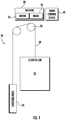
- Figure 1 schematically shows selected portions of an elevator system 20 including an elevator car 22 and counterweight 24.
- a traction sheave 26 associated with a machine 28 selectively controls movement of a load bearing assembly 30, which suspends the elevator car 22 and counterweight 24, to control the movement or position of the elevator car 22.
- the machine 28 includes a motor 32 and a brake 34.
- a brake control device 40 controls operation of the brake 34 under at least some circumstances.
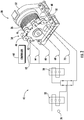
- FIG. 2 schematically illustrates an example embodiment of an elevator brake system including a plurality of brake applicators 42, 44, 46, 48 and 50.
- the brake applicators 42-50 are calipers that operate in a manner known within the elevator industry by applying a braking force in the absence of electrical power supplied to the actuators 42-50.
- a mechanical spring applies the brake force in the absence of electrical power.
- the brake applicators 42-50 use electrical power to release the braking force, which is referred to as lifting the brake.
- the brake control device 40 includes at least one primary switch 52 that is configured for the current and voltage loads associated with operating the brake applicators 42-50.
- the inductive characteristics of the brake applicators 42-50 requires a sufficiently robust switch arrangement for reasons understood by those skilled in the art, such as arcing that may occur when the switch is opened.
- the example embodiment of Figure 2 includes two primary switches 52 and 54 to comply with elevator codes.
- the primary switches 52 and 54 selectively allow current to flow from a power source 56 to the brake applicators 42-50.
- the primary switches 52 and 54 operate responsive to the elevator drive (not illustrated) that controls movement of the elevator car 22.
- An example type of switch that is useful as the primary switch 52, 54 is a contactor switch that is rated for the conditions expected when disconnecting the brake applicators 42-50 from the power source 56.
- the brake control device 40 includes a controller 60, such as a processor and associated memory, for controlling operation of the primary switches 52 and 54 at least to conduct a test of the brake applicators 42-50.
- a controller 60 such as a processor and associated memory
- the brake control device 40 includes a plurality of secondary switches 62, 64, 66, 68 and 70 between the brake actuators 42-50 and the primary switches 52, 54.
- each one of the secondary switches 62-70 is associated with one of the brake applicators 42-50.
- the controller 60 controls the secondary switches on a selective basis at least for conducting a test of the brake applicators 42-50.
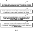
- Figure 3 is a flowchart diagram 80 that summarizes an example test procedure.
- the controller 60 controls the primary switches 52 and 54 to be in a first condition in which the primary switches 52 and 54 prevent electric current from flowing to all of the brake applicators 42-50.
- the primary switches 52 and 54 are open or otherwise non-conducting. Given the location of the secondary switches 62-70, no current flows through any of them when the primary switches 52, 54 are in the first condition.
- the controller 60 opens at least one selected secondary switch, such as the secondary switch 62, while the primary switches 52 and 54 are in the first condition.
- the controller 60 controls the primary switches 52 and 54 to be in a second condition in which the primary switches 52 and 54 allow current flow to the brake applicators 42-50 while the selected secondary switch is open. Since the secondary switch 62 is open in this example scenario, no current flows to the brake applicator 42 when the primary switches 52 and 54 are placed in the second condition to allow current flow through them.
- the second condition includes the primary switches 52 and 54 being closed or otherwise allowing for current flow.
- the controller 60 determines a brake application condition of the brake applicators 42-50 while the secondary switch 62 is open and the primary switches 52 and 54 are in the second condition.
- the brake applicator 42 is expected to be applying a braking force and the others are expected to be lifted.
- the brake application condition determined by the controller at 88 may include movement or position of the components of each brake applicator 42-50 (e.g., an open or closed position), and any other feature of interest for a particular installation.
- the brake applicators 42-50 each include at least one sensor that provides an indication to the controller 60 regarding the brake application condition.
- the brake application condition determination at 88 may include the elevator drive applying a selected level of torque to the elevator motor 32 so that velocity or position feedback information provides an indication if the brake applicator 42 is able to prevent rotation at that torque level.
- the controller 60 subsequently controls the primary switches 52 and 54 to return to the first condition so that no power is supplied to the brake applicators 42-50.
- the secondary switch 62 can then be closed and the controller 60 can open any other one or more of the secondary switches for purposes of testing another one of the brake applicators.
- the location of the secondary switches 62-70 between the primary switches 52 and 54 and the brake applicators 42-50 allows for testing the individual brake applicators.
- the secondary switches 62-70 may be much less robust compared to the primary switches 52 and 54. This allows for including the capability of testing the individual brake applicators 42-50 without requiring multiple sets of primary switches, which are more expensive.
- By selectively opening or closing the secondary switches 62-70 only when no power is provided to the brake applicators and the primary switches 52 and 54 are in the first condition allows for using less expensive secondary switches and providing individualized brake applicator testing capability.
- the secondary switches 62-70 may be, for example, relay switches, semiconductor switches, or contactor switches that are less robust and less expensive than the type of contactor switches used as the primary switches 52 and 54.
- the controller 60 is configured in some embodiments to perform dynamic testing of more than one of the brake applicators 42-50 at a particular time. Although testing a single brake applicator is described above, some embodiments include testing more than one brake applicator at the same time.
- controller 60 is schematically shown in Figure 2 as a device or component that is distinct from the elevator drive, some embodiments include incorporating the features and capability of the example controller 60 into the elevator drive.
- the disclosed example embodiment provides the capability of testing individual brake applicators in an elevator brake system without introducing an additional primary switch for each of the brake applicators and incurring the additional cost associated with duplicating primary switch capability.
- the strategic position of the secondary switches 62-70 and the strategic control over when those switches are opened or closed provides an effective, reliable and economical way to individually test multiple brake applicators in an elevator brake system.
Landscapes
- Engineering & Computer Science (AREA)
- Automation & Control Theory (AREA)
- Computer Networks & Wireless Communication (AREA)
- Mechanical Engineering (AREA)
- Maintenance And Inspection Apparatuses For Elevators (AREA)
- Elevator Control (AREA)
- Cage And Drive Apparatuses For Elevators (AREA)
Abstract
Description
- A variety of elevator systems are known. Some elevator systems are traction-based and include roping that suspends the elevator car and a counterweight. A machine causes movement of a traction sheave that, in turn, causes movement of the roping for moving the elevator car as desired. The machine typically includes a motor and a brake that respectively cause and resist rotation of the traction sheave.
- The brakes in such elevator systems typically require electrical power to lift the brake otherwise a braking force is applied by a mechanical spring to resist rotation of the traction sheave and corresponding movement of the elevator car. It has proven useful to test elevator system brakes and different approaches have been proposed. One example brake torque detection technique is described in the United States Patent Application Publication No.
2019/0031470 . As the industry moves forward, changes in elevator systems and codes have introduced various challenges for controlling or testing the brakes. - An illustrative example embodiment of an elevator brake control device includes at least one primary switch configured to selectively conduct current for lifting all of a plurality of brake applicators. A plurality of secondary switches are each associated with one of the brake applicators. Each of the secondary switches is configured to selectively conduct current for lifting the associated one of the brake applicators. The plurality of secondary switches are between the primary switch and the associated one of the brake applicators.
- An example embodiment having one or more features of the elevator brake control device of the previous paragraph includes a controller configured to control the at least one primary switch and the plurality of secondary switches, the controller being configured to change a state of a selected one of the secondary switches from a closed state to an open state only while the at least one primary switch is open .
- In an example embodiment having one or more features of the elevator brake control device of any of the previous paragraphs, the controller is configured to open the at least one primary switch to prevent current flow to the brake applicators, open the selected one of the secondary switches while the at least one primary switch is open, and close the at least one primary switch while the selected one of the secondary switches is open.
- In an example embodiment having one or more features of the elevator brake control device of any of the previous paragraphs, the controller is configured to open the at least one primary switch to prevent current flow to the brake applicators, open the selected one of the secondary switches while the at least one primary switch is open, and close the at least one primary switch while the selected one of the secondary switches is open.
- In an example embodiment having one or more features of the elevator brake control device of any of the previous paragraphs, the controller is configured to determine an operation condition of the one of the brake applicators associated with the selected one of the secondary switches while the at least one primary switch is closed and the selected one of the secondary switches is open.
- In an example embodiment having one or more features of the elevator brake control device of any of the previous paragraphs, the controller is further configured to open the at least one primary switch while the selected one of the secondary switches is open, close the selected one of the secondary switches while the at least one primary switch is open, open a second selected one of the secondary switches while the at least one primary switch is open, close the at least one primary switch while the second selected one of the secondary switches is open, and determine an operation condition of the one of the brake applicators associated with the second selected one of the secondary switches while the at least one primary switch is closed and the second selected one of the secondary switches is open.
- An illustrative example embodiment of an elevator brake system includes: a plurality of brake applicators each configured to apply a braking force to prevent rotation of an elevator sheave in the absence of electric current being supplied to the brake applicator; at least one primary switch configured to selectively conduct current to all of the brake applicators for lifting all of the brake applicators; a plurality of secondary switches, each of the secondary switches being associated with one of the brake applicators, each of the secondary switches being configured to selectively conduct current for lifting the associated one of the brake applicators, wherein the plurality of secondary switches are between the at least one primary switch and the associated one of the brake applicators; and a controller configured to control the at least one primary switch and the plurality of secondary switches.
- In an example embodiment having one or more features of the elevator brake system of the previous paragraph, the controller is configured to change a state of a selected one of the secondary switches from a closed state to an open state only while the at least one primary switch is open.
- In an example embodiment having one or more features of the elevator brake system of any of the previous paragraphs, the controller is configured to open the at least one primary switch to prevent current flow to the brake applicators, open the selected one of the secondary switches while the at least one primary switch is open, and close the at least one primary switch while the selected one of the secondary switches is open.
- In an example embodiment having one or more features of the elevator brake system of any of the previous paragraphs, the controller is configured to determine an operation condition of the one of the brake applicators associated with the selected one of the secondary switches while the at least one primary switch is closed and the selected one of the secondary switches is open.
- In an example embodiment having one or more features of the elevator brake system of any of the previous paragraphs, the controller is further configured to open the at least one primary switch while the selected one of the secondary switches is open, close the selected one of the secondary switches while the at least one primary switch is open, open a second selected one of the secondary switches while the at least one primary switch is open, close the at least one primary switch while the second selected one of the secondary switches is open,; and determine an operation condition of the one of the brake applicators associated with the second selected one of the secondary switches while the at least one primary switch is closed and the second selected one of the secondary switches is open.
- In an example embodiment having one or more features of the elevator brake system of any of the previous paragraphs, the brake applicators each comprise a caliper and a sensor that provides an indication of movement of the caliper between an open and a closed condition, and the controller is configured to determine a state of each caliper based on the indication from the sensors, respectively.
- An illustrative example embodiment of a method of testing an elevator brake system having a plurality of brake applicators includes: controlling a primary switch to be in a first condition in which the primary switch prevents electric current from flowing to all of the brake applicators; opening a selected secondary switch between one of the brake applicators and the primary switch while the primary switch is in the first condition; controlling the primary switch to be in a second condition in which the primary switch allows current flow to the brake applicators while the selected secondary switch is open; and determining a brake application condition of the one of the brake applicators while the selected secondary switch is open and the primary switch is in the second condition.
- An example embodiment having one or more features of the method of the previous paragraph includes: controlling the primary switch to be in the first condition while the selected secondary switch is open; closing the selected secondary switch while the primary switch is in the first condition; opening a different selected secondary switch between the primary switch and a different one of the brake applicators while the primary switch is in the first condition; controlling the primary switch to be in the second condition while the second selected secondary switch is open; and determining a brake application condition of the different one of the brake applicators while the primary switch is in the second condition and the second selected secondary switch is open.
- In an example embodiment having one or more features of the method of any of the previous paragraphs, the brake application condition comprises at least one of a position of the one of the brake applicators and a braking force applied by the one of the brake applicators.
- In an example embodiment having one or more features of the method of any of the previous paragraphs, the brake applicators respectively comprise a caliper.
- The various features and advantages of at least one disclosed example embodiment will become apparent to those skilled in the art from the following detailed description. The drawings that accompany the detailed description can be briefly described as follows.
-
-
Figure 1 schematically illustrates selected portions of an elevator system including a brake control device designed according to an embodiment of this invention. -
Figure 2 schematically illustrates an example embodiment of an elevator machine, brake and brake control device designed according to an embodiment of this invention. -
Figure 3 is a flowchart diagram that summarizes a process for testing an elevator brake designed according to an embodiment of this invention. -
Figure 1 schematically shows selected portions of anelevator system 20 including anelevator car 22 andcounterweight 24. Atraction sheave 26 associated with amachine 28 selectively controls movement of aload bearing assembly 30, which suspends theelevator car 22 andcounterweight 24, to control the movement or position of theelevator car 22. Themachine 28 includes amotor 32 and abrake 34. Abrake control device 40 controls operation of thebrake 34 under at least some circumstances. -
Figure 2 schematically illustrates an example embodiment of an elevator brake system including a plurality ofbrake applicators elevator car 22, the brake applicators 42-50 use electrical power to release the braking force, which is referred to as lifting the brake. - In the embodiment of
Figure 2 , thebrake control device 40 includes at least oneprimary switch 52 that is configured for the current and voltage loads associated with operating the brake applicators 42-50. The inductive characteristics of the brake applicators 42-50 requires a sufficiently robust switch arrangement for reasons understood by those skilled in the art, such as arcing that may occur when the switch is opened. - The example embodiment of
Figure 2 includes twoprimary switches primary switches power source 56 to the brake applicators 42-50. During normal elevator operation for providing elevator service to passengers, theprimary switches elevator car 22. An example type of switch that is useful as theprimary switch power source 56. - The
brake control device 40 includes acontroller 60, such as a processor and associated memory, for controlling operation of theprimary switches - The
brake control device 40 includes a plurality ofsecondary switches primary switches controller 60 controls the secondary switches on a selective basis at least for conducting a test of the brake applicators 42-50. -
Figure 3 is a flowchart diagram 80 that summarizes an example test procedure. At 82, thecontroller 60 controls theprimary switches primary switches primary switches primary switches - At 84, the
controller 60 opens at least one selected secondary switch, such as thesecondary switch 62, while theprimary switches - At 86, the
controller 60 controls theprimary switches primary switches secondary switch 62 is open in this example scenario, no current flows to thebrake applicator 42 when theprimary switches primary switches - With the
primary switches secondary switch 62 open while the other secondary switches 64-70 are closed, current flows to the brake applicators 44-50 releasing the braking force of each of those brake applicators. Only thebrake applicator 42 applies a braking force under those circumstances. - At 88, the
controller 60 determines a brake application condition of the brake applicators 42-50 while thesecondary switch 62 is open and theprimary switches brake applicator 42 is expected to be applying a braking force and the others are expected to be lifted. The brake application condition determined by the controller at 88 may include movement or position of the components of each brake applicator 42-50 (e.g., an open or closed position), and any other feature of interest for a particular installation. The brake applicators 42-50 each include at least one sensor that provides an indication to thecontroller 60 regarding the brake application condition. - Since the
secondary switch 62 is open and thebrake applicator 42 should be applying a braking force, the brake application condition determination at 88 may include the elevator drive applying a selected level of torque to theelevator motor 32 so that velocity or position feedback information provides an indication if thebrake applicator 42 is able to prevent rotation at that torque level. - The
controller 60 subsequently controls theprimary switches secondary switch 62 can then be closed and thecontroller 60 can open any other one or more of the secondary switches for purposes of testing another one of the brake applicators. - The location of the secondary switches 62-70 between the
primary switches primary switches primary switches primary switches - Given the manner in which power supply through the
primary switches primary switches - Depending on the selection of secondary switches 62-70, the
controller 60 is configured in some embodiments to perform dynamic testing of more than one of the brake applicators 42-50 at a particular time. Although testing a single brake applicator is described above, some embodiments include testing more than one brake applicator at the same time. - Although the
controller 60 is schematically shown inFigure 2 as a device or component that is distinct from the elevator drive, some embodiments include incorporating the features and capability of theexample controller 60 into the elevator drive. - The disclosed example embodiment provides the capability of testing individual brake applicators in an elevator brake system without introducing an additional primary switch for each of the brake applicators and incurring the additional cost associated with duplicating primary switch capability. The strategic position of the secondary switches 62-70 and the strategic control over when those switches are opened or closed provides an effective, reliable and economical way to individually test multiple brake applicators in an elevator brake system.
- The preceding description is exemplary rather than limiting in nature. Variations and modifications to the disclosed examples may become apparent to those skilled in the art that do not necessarily depart from the essence of this invention. The scope of legal protection given to this invention can only be determined by studying the following claims.
Claims (15)
- An elevator brake control device for controlling an elevator brake including a plurality of brake applicators, the brake control device comprising:at least one primary switch configured to selectively conduct current for lifting all of the brake applicators; anda plurality of secondary switches, each of the secondary switches being associated with one of the brake applicators, each of the secondary switches being configured to selectively conduct current for lifting the associated one of the brake applicators, wherein the plurality of secondary switches are between the at least one primary switch and the associated one of the brake applicators.
- The elevator brake control device of claim 1, comprising a controller configured to control the at least one primary switch and the plurality of secondary switches, the controller being configured to change a state of a selected one of the secondary switches from a closed state to an open state only while the at least one primary switch is open.
- The elevator brake control device of claim 2, wherein the controller is configured to
open the at least one primary switch to prevent current flow to the brake applicators;
open the selected one of the secondary switches while the at least one primary switch is open; and
close the at least one primary switch while the selected one of the secondary switches is open. - The elevator brake control device of claim 3, wherein the controller is configured to
determine an operation condition of the one of the brake applicators associated with the selected one of the secondary switches while the at least one primary switch is closed and the selected one of the secondary switches is open. - The elevator brake control device of claim 3 or 4, wherein the controller is further configured to
open the at least one primary switch while the selected one of the secondary switches is open;
close the selected one of the secondary switches while the at least one primary switch is open;
open a second selected one of the secondary switches while the at least one primary switch is open;
close the at least one primary switch while the second selected one of the secondary switches is open; and
determine an operation condition of the one of the brake applicators associated with the second selected one of the secondary switches while the at least one primary switch is closed and the second selected one of the secondary switches is open. - An elevator brake system, comprising:a plurality of brake applicators each configured to apply a braking force to prevent rotation of an elevator sheave in the absence of electric current being supplied to the brake applicator;at least one primary switch configured to selectively conduct current to all of the brake applicators for lifting all of the brake applicators;a plurality of secondary switches, each of the secondary switches being associated with one of the brake applicators, each of the secondary switches being configured to selectively conduct current for lifting the associated one of the brake applicators, wherein the plurality of secondary switches are between the at least one primary switch and the associated one of the brake applicators; anda controller configured to control the at least one primary switch and the plurality of secondary switches.
- The elevator brake system of claim 6, wherein the controller is configured to change a state of a selected one of the secondary switches from a closed state to an open state only while the at least one primary switch is open.
- The elevator brake system of claim 7, wherein the controller is configured to
open the at least one primary switch to prevent current flow to the brake applicators;
open the selected one of the secondary switches while the at least one primary switch is open; and
close the at least one primary switch while the selected one of the secondary switches is open. - The elevator brake system of claim 8, wherein the controller is configured to
determine an operation condition of the one of the brake applicators associated with the selected one of the secondary switches while the at least one primary switch is closed and the selected one of the secondary switches is open. - The elevator brake system of claim 8 or 9, wherein the controller is further configured to
open the at least one primary switch while the selected one of the secondary switches is open;
close the selected one of the secondary switches while the at least one primary switch is open;
open a second selected one of the secondary switches while the at least one primary switch is open;
close the at least one primary switch while the second selected one of the secondary switches is open; and
determine an operation condition of the one of the brake applicators associated with the second selected one of the secondary switches while the at least one primary switch is closed and the second selected one of the secondary switches is open. - The elevator brake system of any one of claims 6 to 10, wherein
the brake applicators each comprise a caliper and a sensor that provides an indication of movement of the caliper between an open and a closed condition; and
the controller is configured to determine a state of each caliper based on the indication from the sensors, respectively. - A method of testing an elevator brake system that includes a plurality of brake applicators, the method comprising:controlling a primary switch to be in a first condition in which the primary switch prevents electric current from flowing to all of the brake applicators;opening a selected secondary switch between one of the brake applicators and the primary switch while the primary switch is in the first condition;controlling the primary switch to be in a second condition in which the primary switch allows current flow to the brake applicators while the selected secondary switch is open; anddetermining a brake application condition of the one of the brake applicators while the selected secondary switch is open and the primary switch is in the second condition.
- The method of claim 12, comprising
controlling the primary switch to be in the first condition while the selected secondary switch is open;
closing the selected secondary switch while the primary switch is in the first condition;
opening a different selected secondary switch between the primary switch and a different one of the brake applicators while the primary switch is in the first condition;
controlling the primary switch to be in the second condition while the second selected secondary switch is open; and
determining a brake application condition of the different one of the brake applicators while the primary switch is in the second condition and the second selected secondary switch is open. - The method of claim 12 or 13, wherein the brake application condition comprises at least one of a position of the one of the brake applicators and a braking force applied by the one of the brake applicators.
- The method of any one of claims 12 to 14, wherein the brake applicators respectively comprise a caliper.
Applications Claiming Priority (1)
| Application Number | Priority Date | Filing Date | Title |
|---|---|---|---|
| US16/592,180 US20210101777A1 (en) | 2019-10-03 | 2019-10-03 | Elevator brake control |
Publications (2)
| Publication Number | Publication Date |
|---|---|
| EP3800154A1 true EP3800154A1 (en) | 2021-04-07 |
| EP3800154B1 EP3800154B1 (en) | 2022-05-25 |
Family
ID=72709221
Family Applications (1)
| Application Number | Title | Priority Date | Filing Date |
|---|---|---|---|
| EP20199451.4A Active EP3800154B1 (en) | 2019-10-03 | 2020-09-30 | Elevator brake control device, elevator brake system and method of testing such elevator brake system |
Country Status (3)
| Country | Link |
|---|---|
| US (1) | US20210101777A1 (en) |
| EP (1) | EP3800154B1 (en) |
| CN (1) | CN112607645B (en) |
Families Citing this family (1)
| Publication number | Priority date | Publication date | Assignee | Title |
|---|---|---|---|---|
| US11807493B1 (en) * | 2018-10-15 | 2023-11-07 | Otis Elevator Company | Retrofitted hoist machine |
Citations (4)
| Publication number | Priority date | Publication date | Assignee | Title |
|---|---|---|---|---|
| EP1731469A1 (en) * | 2004-03-29 | 2006-12-13 | Mitsubishi Denki Kabushiki Kaisha | Method for inspecting operation of actuator and actuator operation inspector |
| EP3006385A1 (en) * | 2014-10-09 | 2016-04-13 | Kone Corporation | A brake controller and an elevator system |
| EP3354611A1 (en) * | 2017-01-30 | 2018-08-01 | Otis Elevator Company | Elevator machine brake control |
| US20190031470A1 (en) | 2017-07-27 | 2019-01-31 | Otis Elevator Company | Brake torque detection for elevator brake |
Family Cites Families (17)
| Publication number | Priority date | Publication date | Assignee | Title |
|---|---|---|---|---|
| JPS5822279A (en) * | 1981-08-04 | 1983-02-09 | 三菱電機株式会社 | Controller for alternating current elevator |
| JPH0645430B2 (en) * | 1988-12-07 | 1994-06-15 | 株式会社日立製作所 | Brake device for elevator hoisting machine and elevator using the same |
| EP1431226B1 (en) * | 2001-09-28 | 2010-07-07 | Mitsubishi Denki Kabushiki Kaisha | Brake controller of elevator |
| CN1553878B (en) * | 2002-07-10 | 2011-08-10 | 三菱电机株式会社 | Elevator controller |
| JP4267335B2 (en) * | 2003-01-30 | 2009-05-27 | 三菱電機株式会社 | Elevator braking control device |
| WO2004083090A1 (en) * | 2003-03-18 | 2004-09-30 | Mitsubishi Denki Kabushiki Kaisha | Emergency stop device for elevator |
| BRPI0318536B1 (en) * | 2003-10-07 | 2015-10-13 | Otis Elevator Co | electric lift rescue system |
| JP5578901B2 (en) * | 2010-03-19 | 2014-08-27 | 東芝エレベータ株式会社 | Elevator brake control device |
| EP3080030B1 (en) * | 2013-12-09 | 2018-03-07 | Inventio AG | Safety circuit for a lift system |
| WO2016113456A1 (en) * | 2015-01-16 | 2016-07-21 | Kone Corporation | A rescue apparatus and an elevator |
| WO2016156658A1 (en) * | 2015-04-01 | 2016-10-06 | Kone Corporation | A brake control apparatus and a method of controlling an elevator brake |
| EP3216735A1 (en) * | 2016-03-10 | 2017-09-13 | Inventio AG | Pulsed opening of elevator brake enabling passenger evacuation |
| CN105836585A (en) * | 2016-05-17 | 2016-08-10 | 上海新时达电气股份有限公司 | Accidental car movement protection circuit and method |
| CN106081989A (en) * | 2016-07-14 | 2016-11-09 | 杭州奥立达电梯有限公司 | A kind of elevator internal contracting brake detection device and method |
| EP3351499B1 (en) * | 2017-01-24 | 2020-11-18 | Otis Elevator Company | Elevator system |
| EP3403967B1 (en) * | 2017-05-15 | 2019-07-03 | KONE Corporation | A current cut-off arrangement of an elevator |
| EP3617110B1 (en) * | 2018-08-30 | 2022-02-23 | KONE Corporation | Elevator motor drive including safety control of elevator in case of power failure |
-
2019
- 2019-10-03 US US16/592,180 patent/US20210101777A1/en not_active Abandoned
-
2020
- 2020-09-29 CN CN202011047639.7A patent/CN112607645B/en not_active Expired - Fee Related
- 2020-09-30 EP EP20199451.4A patent/EP3800154B1/en active Active
Patent Citations (4)
| Publication number | Priority date | Publication date | Assignee | Title |
|---|---|---|---|---|
| EP1731469A1 (en) * | 2004-03-29 | 2006-12-13 | Mitsubishi Denki Kabushiki Kaisha | Method for inspecting operation of actuator and actuator operation inspector |
| EP3006385A1 (en) * | 2014-10-09 | 2016-04-13 | Kone Corporation | A brake controller and an elevator system |
| EP3354611A1 (en) * | 2017-01-30 | 2018-08-01 | Otis Elevator Company | Elevator machine brake control |
| US20190031470A1 (en) | 2017-07-27 | 2019-01-31 | Otis Elevator Company | Brake torque detection for elevator brake |
Also Published As
| Publication number | Publication date |
|---|---|
| EP3800154B1 (en) | 2022-05-25 |
| CN112607645A (en) | 2021-04-06 |
| US20210101777A1 (en) | 2021-04-08 |
| CN112607645B (en) | 2022-08-23 |
Similar Documents
| Publication | Publication Date | Title |
|---|---|---|
| EP1685056B1 (en) | Elevator brake and brake control circuit | |
| CN101646619B (en) | Elevator device | |
| US9617117B2 (en) | Elevator brake control including a solid state switch in series with a relay switch | |
| US8365872B2 (en) | Elevator device having the plurality of hoisting machines | |
| US11542118B2 (en) | Brake control apparatus and a method of controlling an elevator brake | |
| EP2630070B9 (en) | Braking apparatus | |
| EP2670696B1 (en) | Method and arrangement for renewing the braking force of a brake of a hoisting machine | |
| EP2107029A1 (en) | Elevator apparatus | |
| JPWO2007108068A1 (en) | Elevator equipment | |
| EP3800154B1 (en) | Elevator brake control device, elevator brake system and method of testing such elevator brake system | |
| AU2018200294B2 (en) | Elevator machine brake control | |
| EP2090540A1 (en) | Elevator system | |
| EP2457861A1 (en) | Control device for elevator | |
| CN107697772A (en) | Elevator | |
| CN115362114B (en) | Method for checking the current functional state of the brake of an elevator system and elevator system equipped accordingly | |
| JP2014118299A (en) | Elevator device | |
| HK1198583B (en) | Elevator brake control |
Legal Events
| Date | Code | Title | Description |
|---|---|---|---|
| PUAI | Public reference made under article 153(3) epc to a published international application that has entered the european phase |
Free format text: ORIGINAL CODE: 0009012 |
|
| STAA | Information on the status of an ep patent application or granted ep patent |
Free format text: STATUS: THE APPLICATION HAS BEEN PUBLISHED |
|
| AK | Designated contracting states |
Kind code of ref document: A1 Designated state(s): AL AT BE BG CH CY CZ DE DK EE ES FI FR GB GR HR HU IE IS IT LI LT LU LV MC MK MT NL NO PL PT RO RS SE SI SK SM TR |
|
| AX | Request for extension of the european patent |
Extension state: BA ME |
|
| STAA | Information on the status of an ep patent application or granted ep patent |
Free format text: STATUS: REQUEST FOR EXAMINATION WAS MADE |
|
| 17P | Request for examination filed |
Effective date: 20211007 |
|
| RBV | Designated contracting states (corrected) |
Designated state(s): AL AT BE BG CH CY CZ DE DK EE ES FI FR GB GR HR HU IE IS IT LI LT LU LV MC MK MT NL NO PL PT RO RS SE SI SK SM TR |
|
| GRAP | Despatch of communication of intention to grant a patent |
Free format text: ORIGINAL CODE: EPIDOSNIGR1 |
|
| STAA | Information on the status of an ep patent application or granted ep patent |
Free format text: STATUS: GRANT OF PATENT IS INTENDED |
|
| INTG | Intention to grant announced |
Effective date: 20211203 |
|
| GRAS | Grant fee paid |
Free format text: ORIGINAL CODE: EPIDOSNIGR3 |
|
| GRAA | (expected) grant |
Free format text: ORIGINAL CODE: 0009210 |
|
| STAA | Information on the status of an ep patent application or granted ep patent |
Free format text: STATUS: THE PATENT HAS BEEN GRANTED |
|
| AK | Designated contracting states |
Kind code of ref document: B1 Designated state(s): AL AT BE BG CH CY CZ DE DK EE ES FI FR GB GR HR HU IE IS IT LI LT LU LV MC MK MT NL NO PL PT RO RS SE SI SK SM TR |
|
| REG | Reference to a national code |
Ref country code: GB Ref legal event code: FG4D |
|
| REG | Reference to a national code |
Ref country code: CH Ref legal event code: EP |
|
| REG | Reference to a national code |
Ref country code: DE Ref legal event code: R096 Ref document number: 602020003288 Country of ref document: DE |
|
| REG | Reference to a national code |
Ref country code: AT Ref legal event code: REF Ref document number: 1494189 Country of ref document: AT Kind code of ref document: T Effective date: 20220615 |
|
| REG | Reference to a national code |
Ref country code: IE Ref legal event code: FG4D |
|
| REG | Reference to a national code |
Ref country code: LT Ref legal event code: MG9D |
|
| REG | Reference to a national code |
Ref country code: NL Ref legal event code: MP Effective date: 20220525 |
|
| REG | Reference to a national code |
Ref country code: AT Ref legal event code: MK05 Ref document number: 1494189 Country of ref document: AT Kind code of ref document: T Effective date: 20220525 |
|
| PG25 | Lapsed in a contracting state [announced via postgrant information from national office to epo] |
Ref country code: SE Free format text: LAPSE BECAUSE OF FAILURE TO SUBMIT A TRANSLATION OF THE DESCRIPTION OR TO PAY THE FEE WITHIN THE PRESCRIBED TIME-LIMIT Effective date: 20220525 Ref country code: PT Free format text: LAPSE BECAUSE OF FAILURE TO SUBMIT A TRANSLATION OF THE DESCRIPTION OR TO PAY THE FEE WITHIN THE PRESCRIBED TIME-LIMIT Effective date: 20220926 Ref country code: NO Free format text: LAPSE BECAUSE OF FAILURE TO SUBMIT A TRANSLATION OF THE DESCRIPTION OR TO PAY THE FEE WITHIN THE PRESCRIBED TIME-LIMIT Effective date: 20220825 Ref country code: NL Free format text: LAPSE BECAUSE OF FAILURE TO SUBMIT A TRANSLATION OF THE DESCRIPTION OR TO PAY THE FEE WITHIN THE PRESCRIBED TIME-LIMIT Effective date: 20220525 Ref country code: LT Free format text: LAPSE BECAUSE OF FAILURE TO SUBMIT A TRANSLATION OF THE DESCRIPTION OR TO PAY THE FEE WITHIN THE PRESCRIBED TIME-LIMIT Effective date: 20220525 Ref country code: HR Free format text: LAPSE BECAUSE OF FAILURE TO SUBMIT A TRANSLATION OF THE DESCRIPTION OR TO PAY THE FEE WITHIN THE PRESCRIBED TIME-LIMIT Effective date: 20220525 Ref country code: GR Free format text: LAPSE BECAUSE OF FAILURE TO SUBMIT A TRANSLATION OF THE DESCRIPTION OR TO PAY THE FEE WITHIN THE PRESCRIBED TIME-LIMIT Effective date: 20220826 Ref country code: FI Free format text: LAPSE BECAUSE OF FAILURE TO SUBMIT A TRANSLATION OF THE DESCRIPTION OR TO PAY THE FEE WITHIN THE PRESCRIBED TIME-LIMIT Effective date: 20220525 Ref country code: BG Free format text: LAPSE BECAUSE OF FAILURE TO SUBMIT A TRANSLATION OF THE DESCRIPTION OR TO PAY THE FEE WITHIN THE PRESCRIBED TIME-LIMIT Effective date: 20220825 Ref country code: AT Free format text: LAPSE BECAUSE OF FAILURE TO SUBMIT A TRANSLATION OF THE DESCRIPTION OR TO PAY THE FEE WITHIN THE PRESCRIBED TIME-LIMIT Effective date: 20220525 |
|
| PG25 | Lapsed in a contracting state [announced via postgrant information from national office to epo] |
Ref country code: RS Free format text: LAPSE BECAUSE OF FAILURE TO SUBMIT A TRANSLATION OF THE DESCRIPTION OR TO PAY THE FEE WITHIN THE PRESCRIBED TIME-LIMIT Effective date: 20220525 Ref country code: PL Free format text: LAPSE BECAUSE OF FAILURE TO SUBMIT A TRANSLATION OF THE DESCRIPTION OR TO PAY THE FEE WITHIN THE PRESCRIBED TIME-LIMIT Effective date: 20220525 Ref country code: LV Free format text: LAPSE BECAUSE OF FAILURE TO SUBMIT A TRANSLATION OF THE DESCRIPTION OR TO PAY THE FEE WITHIN THE PRESCRIBED TIME-LIMIT Effective date: 20220525 Ref country code: IS Free format text: LAPSE BECAUSE OF FAILURE TO SUBMIT A TRANSLATION OF THE DESCRIPTION OR TO PAY THE FEE WITHIN THE PRESCRIBED TIME-LIMIT Effective date: 20220925 |
|
| PG25 | Lapsed in a contracting state [announced via postgrant information from national office to epo] |
Ref country code: SM Free format text: LAPSE BECAUSE OF FAILURE TO SUBMIT A TRANSLATION OF THE DESCRIPTION OR TO PAY THE FEE WITHIN THE PRESCRIBED TIME-LIMIT Effective date: 20220525 Ref country code: SK Free format text: LAPSE BECAUSE OF FAILURE TO SUBMIT A TRANSLATION OF THE DESCRIPTION OR TO PAY THE FEE WITHIN THE PRESCRIBED TIME-LIMIT Effective date: 20220525 Ref country code: RO Free format text: LAPSE BECAUSE OF FAILURE TO SUBMIT A TRANSLATION OF THE DESCRIPTION OR TO PAY THE FEE WITHIN THE PRESCRIBED TIME-LIMIT Effective date: 20220525 Ref country code: ES Free format text: LAPSE BECAUSE OF FAILURE TO SUBMIT A TRANSLATION OF THE DESCRIPTION OR TO PAY THE FEE WITHIN THE PRESCRIBED TIME-LIMIT Effective date: 20220525 Ref country code: EE Free format text: LAPSE BECAUSE OF FAILURE TO SUBMIT A TRANSLATION OF THE DESCRIPTION OR TO PAY THE FEE WITHIN THE PRESCRIBED TIME-LIMIT Effective date: 20220525 Ref country code: DK Free format text: LAPSE BECAUSE OF FAILURE TO SUBMIT A TRANSLATION OF THE DESCRIPTION OR TO PAY THE FEE WITHIN THE PRESCRIBED TIME-LIMIT Effective date: 20220525 Ref country code: CZ Free format text: LAPSE BECAUSE OF FAILURE TO SUBMIT A TRANSLATION OF THE DESCRIPTION OR TO PAY THE FEE WITHIN THE PRESCRIBED TIME-LIMIT Effective date: 20220525 |
|
| REG | Reference to a national code |
Ref country code: DE Ref legal event code: R097 Ref document number: 602020003288 Country of ref document: DE |
|
| PG25 | Lapsed in a contracting state [announced via postgrant information from national office to epo] |
Ref country code: AL Free format text: LAPSE BECAUSE OF FAILURE TO SUBMIT A TRANSLATION OF THE DESCRIPTION OR TO PAY THE FEE WITHIN THE PRESCRIBED TIME-LIMIT Effective date: 20220525 |
|
| PLBE | No opposition filed within time limit |
Free format text: ORIGINAL CODE: 0009261 |
|
| STAA | Information on the status of an ep patent application or granted ep patent |
Free format text: STATUS: NO OPPOSITION FILED WITHIN TIME LIMIT |
|
| PG25 | Lapsed in a contracting state [announced via postgrant information from national office to epo] |
Ref country code: MC Free format text: LAPSE BECAUSE OF FAILURE TO SUBMIT A TRANSLATION OF THE DESCRIPTION OR TO PAY THE FEE WITHIN THE PRESCRIBED TIME-LIMIT Effective date: 20220525 |
|
| 26N | No opposition filed |
Effective date: 20230228 |
|
| REG | Reference to a national code |
Ref country code: BE Ref legal event code: MM Effective date: 20220930 |
|
| PG25 | Lapsed in a contracting state [announced via postgrant information from national office to epo] |
Ref country code: SI Free format text: LAPSE BECAUSE OF FAILURE TO SUBMIT A TRANSLATION OF THE DESCRIPTION OR TO PAY THE FEE WITHIN THE PRESCRIBED TIME-LIMIT Effective date: 20220525 |
|
| PG25 | Lapsed in a contracting state [announced via postgrant information from national office to epo] |
Ref country code: LU Free format text: LAPSE BECAUSE OF NON-PAYMENT OF DUE FEES Effective date: 20220930 |
|
| PG25 | Lapsed in a contracting state [announced via postgrant information from national office to epo] |
Ref country code: IE Free format text: LAPSE BECAUSE OF NON-PAYMENT OF DUE FEES Effective date: 20220930 |
|
| PG25 | Lapsed in a contracting state [announced via postgrant information from national office to epo] |
Ref country code: BE Free format text: LAPSE BECAUSE OF NON-PAYMENT OF DUE FEES Effective date: 20220930 |
|
| PGFP | Annual fee paid to national office [announced via postgrant information from national office to epo] |
Ref country code: FR Payment date: 20230822 Year of fee payment: 4 Ref country code: DE Payment date: 20230822 Year of fee payment: 4 |
|
| PG25 | Lapsed in a contracting state [announced via postgrant information from national office to epo] |
Ref country code: IT Free format text: LAPSE BECAUSE OF FAILURE TO SUBMIT A TRANSLATION OF THE DESCRIPTION OR TO PAY THE FEE WITHIN THE PRESCRIBED TIME-LIMIT Effective date: 20220525 |
|
| PG25 | Lapsed in a contracting state [announced via postgrant information from national office to epo] |
Ref country code: CY Free format text: LAPSE BECAUSE OF FAILURE TO SUBMIT A TRANSLATION OF THE DESCRIPTION OR TO PAY THE FEE WITHIN THE PRESCRIBED TIME-LIMIT Effective date: 20220525 |
|
| REG | Reference to a national code |
Ref country code: CH Ref legal event code: PL |
|
| PG25 | Lapsed in a contracting state [announced via postgrant information from national office to epo] |
Ref country code: MK Free format text: LAPSE BECAUSE OF FAILURE TO SUBMIT A TRANSLATION OF THE DESCRIPTION OR TO PAY THE FEE WITHIN THE PRESCRIBED TIME-LIMIT Effective date: 20220525 |
|
| PG25 | Lapsed in a contracting state [announced via postgrant information from national office to epo] |
Ref country code: TR Free format text: LAPSE BECAUSE OF FAILURE TO SUBMIT A TRANSLATION OF THE DESCRIPTION OR TO PAY THE FEE WITHIN THE PRESCRIBED TIME-LIMIT Effective date: 20220525 |
|
| PG25 | Lapsed in a contracting state [announced via postgrant information from national office to epo] |
Ref country code: CH Free format text: LAPSE BECAUSE OF NON-PAYMENT OF DUE FEES Effective date: 20230930 |
|
| PG25 | Lapsed in a contracting state [announced via postgrant information from national office to epo] |
Ref country code: HU Free format text: LAPSE BECAUSE OF FAILURE TO SUBMIT A TRANSLATION OF THE DESCRIPTION OR TO PAY THE FEE WITHIN THE PRESCRIBED TIME-LIMIT; INVALID AB INITIO Effective date: 20200930 Ref country code: CH Free format text: LAPSE BECAUSE OF NON-PAYMENT OF DUE FEES Effective date: 20230930 |
|
| PG25 | Lapsed in a contracting state [announced via postgrant information from national office to epo] |
Ref country code: MT Free format text: LAPSE BECAUSE OF FAILURE TO SUBMIT A TRANSLATION OF THE DESCRIPTION OR TO PAY THE FEE WITHIN THE PRESCRIBED TIME-LIMIT Effective date: 20220525 |
|
| PG25 | Lapsed in a contracting state [announced via postgrant information from national office to epo] |
Ref country code: BG Free format text: LAPSE BECAUSE OF FAILURE TO SUBMIT A TRANSLATION OF THE DESCRIPTION OR TO PAY THE FEE WITHIN THE PRESCRIBED TIME-LIMIT Effective date: 20220525 |
|
| PG25 | Lapsed in a contracting state [announced via postgrant information from national office to epo] |
Ref country code: BG Free format text: LAPSE BECAUSE OF FAILURE TO SUBMIT A TRANSLATION OF THE DESCRIPTION OR TO PAY THE FEE WITHIN THE PRESCRIBED TIME-LIMIT Effective date: 20220525 |
|
| REG | Reference to a national code |
Ref country code: DE Ref legal event code: R119 Ref document number: 602020003288 Country of ref document: DE |
|
| GBPC | Gb: european patent ceased through non-payment of renewal fee |
Effective date: 20240930 |
|
| PG25 | Lapsed in a contracting state [announced via postgrant information from national office to epo] |
Ref country code: DE Free format text: LAPSE BECAUSE OF NON-PAYMENT OF DUE FEES Effective date: 20250401 |
|
| PG25 | Lapsed in a contracting state [announced via postgrant information from national office to epo] |
Ref country code: GB Free format text: LAPSE BECAUSE OF NON-PAYMENT OF DUE FEES Effective date: 20240930 |
|
| PG25 | Lapsed in a contracting state [announced via postgrant information from national office to epo] |
Ref country code: FR Free format text: LAPSE BECAUSE OF NON-PAYMENT OF DUE FEES Effective date: 20240930 |