EP3800052A1 - A circuit and method for detecting the presence of dirt particles in an inkjet print head - Google Patents
A circuit and method for detecting the presence of dirt particles in an inkjet print head Download PDFInfo
- Publication number
- EP3800052A1 EP3800052A1 EP19200923.1A EP19200923A EP3800052A1 EP 3800052 A1 EP3800052 A1 EP 3800052A1 EP 19200923 A EP19200923 A EP 19200923A EP 3800052 A1 EP3800052 A1 EP 3800052A1
- Authority
- EP
- European Patent Office
- Prior art keywords
- pressure wave
- residual pressure
- ejection unit
- energy
- liquid
- Prior art date
- Legal status (The legal status is an assumption and is not a legal conclusion. Google has not performed a legal analysis and makes no representation as to the accuracy of the status listed.)
- Granted
Links
Images



Classifications
-
- B—PERFORMING OPERATIONS; TRANSPORTING
- B41—PRINTING; LINING MACHINES; TYPEWRITERS; STAMPS
- B41J—TYPEWRITERS; SELECTIVE PRINTING MECHANISMS, i.e. MECHANISMS PRINTING OTHERWISE THAN FROM A FORME; CORRECTION OF TYPOGRAPHICAL ERRORS
- B41J2/00—Typewriters or selective printing mechanisms characterised by the printing or marking process for which they are designed
- B41J2/005—Typewriters or selective printing mechanisms characterised by the printing or marking process for which they are designed characterised by bringing liquid or particles selectively into contact with a printing material
- B41J2/01—Ink jet
- B41J2/015—Ink jet characterised by the jet generation process
- B41J2/04—Ink jet characterised by the jet generation process generating single droplets or particles on demand
- B41J2/045—Ink jet characterised by the jet generation process generating single droplets or particles on demand by pressure, e.g. electromechanical transducers
- B41J2/04501—Control methods or devices therefor, e.g. driver circuits, control circuits
- B41J2/0451—Control methods or devices therefor, e.g. driver circuits, control circuits for detecting failure, e.g. clogging, malfunctioning actuator
-
- B—PERFORMING OPERATIONS; TRANSPORTING
- B41—PRINTING; LINING MACHINES; TYPEWRITERS; STAMPS
- B41J—TYPEWRITERS; SELECTIVE PRINTING MECHANISMS, i.e. MECHANISMS PRINTING OTHERWISE THAN FROM A FORME; CORRECTION OF TYPOGRAPHICAL ERRORS
- B41J2/00—Typewriters or selective printing mechanisms characterised by the printing or marking process for which they are designed
- B41J2/005—Typewriters or selective printing mechanisms characterised by the printing or marking process for which they are designed characterised by bringing liquid or particles selectively into contact with a printing material
- B41J2/01—Ink jet
- B41J2/015—Ink jet characterised by the jet generation process
- B41J2/04—Ink jet characterised by the jet generation process generating single droplets or particles on demand
- B41J2/045—Ink jet characterised by the jet generation process generating single droplets or particles on demand by pressure, e.g. electromechanical transducers
- B41J2/04501—Control methods or devices therefor, e.g. driver circuits, control circuits
- B41J2/04571—Control methods or devices therefor, e.g. driver circuits, control circuits detecting viscosity
-
- B—PERFORMING OPERATIONS; TRANSPORTING
- B41—PRINTING; LINING MACHINES; TYPEWRITERS; STAMPS
- B41J—TYPEWRITERS; SELECTIVE PRINTING MECHANISMS, i.e. MECHANISMS PRINTING OTHERWISE THAN FROM A FORME; CORRECTION OF TYPOGRAPHICAL ERRORS
- B41J2/00—Typewriters or selective printing mechanisms characterised by the printing or marking process for which they are designed
- B41J2/005—Typewriters or selective printing mechanisms characterised by the printing or marking process for which they are designed characterised by bringing liquid or particles selectively into contact with a printing material
- B41J2/01—Ink jet
- B41J2/015—Ink jet characterised by the jet generation process
- B41J2/04—Ink jet characterised by the jet generation process generating single droplets or particles on demand
- B41J2/045—Ink jet characterised by the jet generation process generating single droplets or particles on demand by pressure, e.g. electromechanical transducers
- B41J2/04501—Control methods or devices therefor, e.g. driver circuits, control circuits
- B41J2/04581—Control methods or devices therefor, e.g. driver circuits, control circuits controlling heads based on piezoelectric elements
-
- B—PERFORMING OPERATIONS; TRANSPORTING
- B41—PRINTING; LINING MACHINES; TYPEWRITERS; STAMPS
- B41J—TYPEWRITERS; SELECTIVE PRINTING MECHANISMS, i.e. MECHANISMS PRINTING OTHERWISE THAN FROM A FORME; CORRECTION OF TYPOGRAPHICAL ERRORS
- B41J2/00—Typewriters or selective printing mechanisms characterised by the printing or marking process for which they are designed
- B41J2/005—Typewriters or selective printing mechanisms characterised by the printing or marking process for which they are designed characterised by bringing liquid or particles selectively into contact with a printing material
- B41J2/01—Ink jet
- B41J2/135—Nozzles
- B41J2/14—Structure thereof only for on-demand ink jet heads
- B41J2002/14354—Sensor in each pressure chamber
Definitions
- the present invention generally pertains to detecting disturbances in a pressure chamber or nozzle of an inkjet print head, in particular a piezo-actuated inkjet print head.
- the invention relates to detecting the presence of dirt particles leading to abnormal ejection of ink.
- the invention allows detecting dirt/debris entering through the ink path of the printer, which may be caused by other elements of the printer in said ink path (as for example plastic debris from an improperly placed combination of ink stirrer - plastic ink jar).
- a method of operating a droplet ejection device according to claim 1 is provided.
- a droplet ejection device is provided.
- the present invention relates to a method for detecting an operating state of an ejection unit during the printing of an object of a print job comprising one or more objects, wherein the ejection unit is arranged to eject droplets of a liquid and comprises a plurality of nozzles, a liquid duct connected to the nozzle, and an electro-mechanical transducer arranged to create an acoustic pressure wave in the liquid in the duct.
- Said method comprises a step of actuating the electro-mechanical transducer, and subsequently sensing the residual pressure wave that was generated in the liquid.
- the resonance frequency of the sensed residual pressure wave is measured, and it is determined whether the ejection unit is in an operative state or in a malfunctioning state based upon whether the difference between the measured resonance frequency of the residual pressure wave and the resonance frequency of a reference residual pressure wave of a correctly functioning ejection unit exceeds a resonance frequency threshold amount.
- the ejection unit if it is determined in previous step that the ejection unit is in a malfunctioning state, measuring the energy of the sensed residual pressure wave and determining that the ejection unit is in a malfunctioning state due to first cause if the measured energy of the residual pressure wave is lower than the energy of a reference residual pressure wave of a correctly functioning ejection unit at least an energy threshold amount, and is in a malfunctioning state due to a second cause if the measured energy of the residual pressure wave is higher than the energy of a reference residual pressure wave of a correctly functioning ejection unit at least an energy threshold amount.
- the method of the present invention comprises additional steps if it is determined in the previous steps that the ejection unit is in a malfunctioning state.
- the energy of the sensed residual pressure wave is measured. Said measurement can be performed before, subsequently or simultaneous to the above mentioned measurement of the resonance frequency of the sensed residual pressure wave.
- the method of the present invention determines, that the ejection unit is in a malfunctioning state due to first cause if the measured energy of the residual pressure wave is lower than the energy of a reference residual pressure wave of a correctly functioning ejection unit at least an energy threshold amount, and is in a malfunctioning state due to a second cause if the measured energy of the residual pressure wave is higher than the energy of a reference residual pressure wave of a correctly functioning ejection unit at least an energy threshold amount.
- the method of the present invention determines that the first cause of malfunctioning is the presence of a dirt particle inside the duct, and that the second cause of malfunctioning is the presence of a dirt particle at/inside the nozzle.
- the present invention is capable of distinguishing between different causes if malfunctioning, and is therefore capable of implementing adequate countermeasures: stopping the printing processes when the cause of malfunctioning is the presence of a dirt particle inside the duct, and purging and wiping when the cause of malfunctioning is the presence of a dirt particle at/inside the nozzle.
- the latter countermeasure would be ineffective when the cause of malfunctioning is the presence of a dirt particle inside the duct, and purging and wiping in said case would only lead to in waste.
- the method of the present invention allows determining the most adequate measure to counteract a detected malfunctioning.
- the present invention further comprises a step of determining the location of a dirt particle within the length of the duct.
- the present invention further comprises a step of determining the percentage of the duct blocked by the dirt particle.
- the present invention performs the step of determining the percentage of the channel area of the duct blocked by the dirt particle when it is determined that the ejection unit is in a malfunctioning state due to a first cause based upon the amount that the measured energy of the residual pressure wave is higher than the energy of a reference residual pressure wave of a correctly functioning ejection unit.
- the present invention comprises a software product comprising program code on a machine-readable non-transitory medium, the program code, when loaded into a processor of the droplet ejection device of the present invention, causes the processor to perform a method of the present invention.
- the present invention also comprises a droplet ejection device comprising a number of ejection units arranged to eject droplets of a liquid and each comprising a nozzle formed in a nozzle face, a liquid duct connected to the nozzle, and an electro-mechanical transducer arranged to create an acoustic pressure wave in the liquid in the duct, characterized in that at least one of the number of ejection units is associated with a processor configured to perform any of the methods of the present invention.
- the present invention comprises a printing system comprising the droplet ejection device of the present invention, and a software product comprising program code on a machine-readable non-transitory medium, the program code, when loaded into a control unit of the printing system according the present invention, causes the control unit to perform the method according to any of the embodiments of the present invention.
- FIG. 1 A single ejection unit of an ink jet print head is shown in Fig. 1 .
- the print head constitutes an example of a droplet ejection device according to the invention.
- the device comprises a wafer 10 and a support member 12 that are bonded to opposite sides of a thin flexible membrane 14.
- a recess that forms an ink duct 16 is formed in the face of the wafer 10 that engages the membrane 14, e.g. the bottom face in Fig. 1 .
- the ink duct 16 has an essentially rectangular shape.
- An end portion on the left side in Fig. 1 is connected to an ink supply line 18 that passes through the wafer 10 in thickness direction of the wafer and serves for supplying liquid ink to the ink duct 16.
- An opposite end of the ink duct 16, on the right side in Fig. 1 is connected, through an opening in the membrane 14, to a chamber 20 that is formed in the support member 12 and opens out into a nozzle 22 that is formed in a nozzle face 24 constituting the bottom face of the support member.
- the support member 12 Adjacent to the membrane 14 and separated from the chamber 20, the support member 12 forms another cavity 26 accommodating a piezoelectric actuator 28 that is bonded to the membrane 14.
- An ink supply system which has not been shown here keeps the pressure of the liquid ink in the ink duct 16 slightly below the atmospheric pressure, so as to prevent the ink from leaking out through the nozzle 22.
- the nozzle face 24 is made of or coated with a material which is wetted by the ink, so that adhesion forces cause a pool 30 of ink to be formed on the nozzle face 24 around the nozzle 22.
- the pool 30 is delimited on the outward (bottom) side by a meniscus 32a.
- the piezoelectric transducer 28 has electrodes 34 that are connected to an electronic circuit that has been shown in the lower part of Fig. 1 .
- one electrode of the transducer is grounded via a line 36 and a resistor 38.
- Another electrode of the transducer is connected to an output of an amplifier 40 that is feedback-controlled via a feedback network 42, so that a voltage V applied to the transducer will be proportional to a signal on an input line 44 of the amplifier.
- the signal on the input line 44 is generated by a D/A-converter 46 that receives a digital input from a local digital controller 48.
- the controller 48 is connected to a processor 50.
- the processor 50 sends a command to the controller 48 which outputs a digital signal that causes the D/A-converter 46 and the amplifier 40 to apply an actuation pulse to the transducer 28.
- This voltage pulse causes the transducer to deform in a bending mode. More specifically, the transducer 28 is caused to flex downward, so that the membrane 14 which is bonded to the transducer 28 will also flex downward, thereby to increase the volume of the ink duct 16. As a consequence, additional ink will be sucked-in via the supply line 18.
- the membrane 14 will flex back into the original state, so that a positive acoustic pressure wave is generated in the liquid ink in the duct 16.
- This pressure wave propagates to the nozzle 22 and causes an ink droplet to be expelled.
- the pressure wave will then be reflected at the meniscus 32a and will oscillate in the cavity formed between the meniscus and the left end of the duct 16 in Fig. 1 .
- the oscillation will be damped due to the viscosity of the ink.
- the transducer 28 is energized with a quench pulse which has a polarity opposite to that of the actuation pulse and is timed such that the decaying oscillation will be suppressed further by destructive interference.
- the electrodes 34 of the transducer 28 are also connected to an A/D converter 52 which measures a voltage drop across the transducer and also a voltage drop across the resistor 38 and thereby implicitly the current flowing through the transducer.
- Corresponding digital signals S are forwarded to the controller 48 which can derive the impedance of the transducer 28 from these signals.
- the measured electric response (current, voltage, impedance, etc.) is signaled to the processor 50 where the electric response is processed further.
- said malfunctioning can be caused by the presence of a dirt particle whose origin is outside the nozzle 22.
- a dirt particle whose origin is outside the nozzle 22.
- a person skilled in the art would readily understand that there are several different causes for the presence of this type of particle, as for example debris from the printed media, a particle originated in the wiper, etc.
- said malfunctioning can be caused by the presence of a dirt particle whose origin is inside ink duct 16 or ink supply line 18, namely dirt or debris which entered through the ink path of the printer.
- Typical examples are blockages caused by dirt from the print head assembly, large impurities created by pigment accumulation, the presence of residual glue, etc.
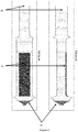
- FIG. 2 the 1-D geometry of a wave model for an ink channel in shown.
- One of the sides 60 of the ink channel is connected to the ink reservoir, while the nozzle 80 is located in the opposite side of the ink channel.
- a piezoelectric actuator 70 also known as piezoelectric transducer, is present on the ink channel.
- actuation pulse when an actuation pulse is generated and applied to the piezoelectric actuator an acoustic pressure wave is generated in the liquid ink in the ink channel.
- This pressure wave propagates to the nozzle 80 and causes an ink droplet to be expelled.
- Fig. 2 shows the state of the ink channel when there is no disturbance in the ink channel that could lead to an abnormal ejection of ink, in contrast with Fig.3 below.
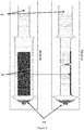
- FIG 3 the 1-D geometry of a wave model for an ink channel in shown, in the case in which a blockage is present in the ink channel, caused by the presence of a particle therein.
- said blockage occupies 95% of the area.
- One of the sides 60a of the ink channel is connected to the ink reservoir, while the nozzle 80a is located in the opposite side of the ink channel.
- a piezoelectric actuator 70a is present on the ink channel.
- the presence of a blockage in the ink channel is likely to cause abnormal functioning behavior when ink is jetted though the nozzle. More specifically, when the blockage occupies a significant part of the ink channel, it is inevitable that the jetting behavior is adversely affected. It has been observed that when a blockage occupies between a 5 - 20% of the ink channel droplet quality is affected, as the blockage causes variation in droplet quality: ejection velocity, ejection angle, etc. Said adverse affection may consist in the nozzle being unable to jet ink in the proper direction (e.g. side shooting nozzles), spurting ink partially contaminated with debris which would inevitably lead to undesired artifacts in the printed image, or the nozzle not being able to jet ink at all leading to a blank in the printed image.
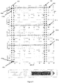
- Figure 4 shows the main variables than have been measured in the residual acoustic pressure wave in the liquid in the duct 16 generated when ink is jetted from a nozzle.
- the four graphs from top to bottom relate respectively to the behavior of the resonance frequency (defined as the resonance frequency of the dominant channel, i.e. the strongest resonance frequency found in the channel), the energy of the residual pressure wave, the dampening factor of the residual pressure wave, and the phase of the residual pressure wave, depending upon the position within the ink channel where a blockage is present, as indicated by the lowermost fifth graph.
- Figure 4 includes a first region 410 that spans across the aforementioned graphs. Said region 410 corresponds in each graph to the residual pressure wave measured when a blockage is present in the position within the ink channel shown in the lowermost fifth graph, which in the case of first region 410 corresponds to a blockage in position five within the ink channel, representing a blockage at the ink inlet side.
- first region 410 two different positions within the waveform have been highlighted, namely 430a and 430b.
- 430a represents the resonance frequency with a blockage occupying a small area of the ink channel, e.g. 5% thereof
- 430a represents the resonance frequency with a blockage occupying a large area of the ink channel, e.g. 95% thereof.
- region 410 represents the waveforms measured when there is presence of a dirt particle close to the ink inlet. From left to right the waveforms represent a presence in the same location but with a growing size, with 430c representing a blockage occupying a small area of the ink channel, e.g. 5% thereof, while 430d representing a blockage occupying a large area of the ink channel, e.g. 95% thereof, as can be readily observed in the lowermost graph.
- the resonance frequency of the residual pressure wave measured can be observed in the uppermost graph when a blockage is present in the aforementioned position within the ink channel. It can be observed in region 410 that the resonance frequency of the measured residual pressure wave is significantly lower than the resonance frequency 401f of a reference healthy nozzle, which is also shown in the uppermost graph. This deviation in resonance frequency determines that the related ejection unit is in malfunctioning state, more particularly when it is determined that an ejection unit is in a malfunctioning state when the observed deviation exceeds a predetermined threshold. Accordingly, reference waveforms 401e, 401d, and 401p represent respectively the energy, dampening factor, and phase of the measured residual pressure wave.
- Figure 4 includes a second region 420 that spans across the aforementioned graphs. Said region 420 corresponds in each graph to the residual pressure wave measured when a blockage is present in the position within the ink channel shown in the lowermost fifth graph, which in the case of first region 420 corresponds to a blockage in position eighty five within the ink channel, representing a blockage at the nozzle side.
- the resonance frequency of the residual pressure wave measured can be observed in the uppermost graph when a blockage is present in the aforementioned position within the ink channel. It can be observed in region 420 that the resonance frequency of the measured residual pressure wave is also significantly lower than the resonance frequency 401f of a reference healthy nozzle, which is also shown in the uppermost graph. This deviation in resonance frequency also determines that the related ejection unit is in malfunctioning state, more particularly when it is determined that an ejection unit is in a malfunctioning state when the observed deviation exceeds a predetermined threshold.
- a significant deviation in the measured resonance frequency is used in the present invention to determine if an ejection unit is in a malfunctioning state.
- Figure 5 shows in its uppermost graph the measured residual pressure wave 501b for a particular blockage together with the residual pressure wave 501a measured from a correctly functioning print head.
- the residual pressure wave has been measured, as a mere example, when a blockage of a 5% exists in position 30.
- a blockage of a 5% implies that 95% of the channel is blocked.
- a blockage of a 100% represented by 502a implies that 0% of the channel is blocked, and therefore, the ejection unit is a functioning properly.
- said uppermost graph of Figure 5 it can observed that there is a severe reduction in resonance frequency of the residual pressure wave, which indicates that a blockage is present.
- Figure 5 shows in its lowermost graph a plurality of measured residual pressure waves 502a, 502b, and 502c for different blockages.
- Residual pressure wave 502a represents the response of a properly functioning ejection unit.
- residual pressure waves 502b and 502c represent the response when there is a blockage in position 30 of respectively 61% (meaning 39% of the ink channel is blocked) and 5% (meaning 95% of the ink channel is blocked).
- the observed reduction in resonance frequency of the residual pressure wave is higher when the blockage leaves a smaller effective area for the ink to flow, i.e. there is a bigger blockage in the ink flow.
- step S1 comprises actuating the electro-mechanical transducer 28 to generate a pressure wave in the liquid.
- step S2 the residual pressure wave generated in the liquid is sensed in step S2.
- Step S3 of the present invention relates to measuring the resonance frequency of the sensed residual pressure wave.
- step S4 determines whether the ejection unit is in an operative state or in a malfunctioning state based upon the difference between the resonance frequency of the sensed residual pressure wave and the resonance frequency of a reference residual pressure wave of a correctly functioning ejection unit, wherein the ejection unit is determined to be in a malfunctioning state when the measured resonance frequency of the residual pressure wave is lower than the resonance frequency of a reference residual pressure wave of a correctly functioning ejection unit at least a resonance frequency threshold amount.
- Step S5 of the present invention relates to steps taken if it is determined in step S4 that the ejection unit is in a malfunctioning state.
- a first step comprises measuring the energy of the sensed residual pressure wave, and subsequently determining that the ejection unit is in a malfunctioning state due to a first cause if the measured energy of the residual pressure wave is lower than the energy of a reference residual pressure wave of a correctly functioning ejection unit at least an energy threshold amount, and is in a malfunctioning state due to a second cause if the measured energy of the residual pressure wave is higher than the energy of a reference residual pressure wave of a correctly functioning ejection unit at least an energy threshold amount.
- said first cause of malfunctioning is the presence of a dirt particle inside the duct 16
- the second cause of malfunctioning is the presence of a dirt particle at/inside the nozzle 22.
- steps S3 and S4 and the group of steps S5 and S6 can be performed in different order. It is possible to perform the determinations of steps S5 and S6 related to determining whether there have been significant changes in the energy of a residual pressure wave generated before the determinations in steps S3 and S4. Also, a person of skill in the art would readily recognize that both groups of steps can be performed concurrently.
Landscapes
- Ink Jet (AREA)
Abstract
Description
- The present invention generally pertains to detecting disturbances in a pressure chamber or nozzle of an inkjet print head, in particular a piezo-actuated inkjet print head.
- More particularly, the invention relates to detecting the presence of dirt particles leading to abnormal ejection of ink.
- During the execution of print processes several faults can disturb the jetting of a nozzle. For example, blocking of an ink nozzle due to the presence of a dirt particle is one of the most common causes of malfunction in ink jetting.
- However, it remains an unsolved problem being able to determine whether the malfunctioning is caused by the presence of a dirt particle originated outside the nozzle (e.g. paper dust, an outside particle causing malfunctioning due to bad wiping, etc.), or by the presence of a dirt particle originated inside the ink channel (e.g. caused by a poor print head assembly, large ink pigment accumulation, etc.). This is important because when a dirt particle is located inside the ink channel it is difficult to remove said particle by purging the ink out and wiping the nozzle. Therefore, an accurate differentiation allows skipping this step, thereby reducing ink waste.
- Also, the invention allows detecting dirt/debris entering through the ink path of the printer, which may be caused by other elements of the printer in said ink path (as for example plastic debris from an improperly placed combination of ink stirrer - plastic ink jar).
- As a consequence, it is desired to have a method for detecting the presence of dirt particles in an inkjet print head that is further capable of distinguishing the location of the dirt particle such that appropriate countermeasures can be applied.
- In an aspect of the present invention, a method of operating a droplet ejection device according to claim 1 is provided. In another aspect of the present invention, a droplet ejection device is provided.
- In an embodiment, the present invention relates to a method for detecting an operating state of an ejection unit during the printing of an object of a print job comprising one or more objects, wherein the ejection unit is arranged to eject droplets of a liquid and comprises a plurality of nozzles, a liquid duct connected to the nozzle, and an electro-mechanical transducer arranged to create an acoustic pressure wave in the liquid in the duct. Said method comprises a step of actuating the electro-mechanical transducer, and subsequently sensing the residual pressure wave that was generated in the liquid.
- Then, the resonance frequency of the sensed residual pressure wave is measured, and it is determined whether the ejection unit is in an operative state or in a malfunctioning state based upon whether the difference between the measured resonance frequency of the residual pressure wave and the resonance frequency of a reference residual pressure wave of a correctly functioning ejection unit exceeds a resonance frequency threshold amount.
- if it is determined in previous step that the ejection unit is in a malfunctioning state, measuring the energy of the sensed residual pressure wave and determining that the ejection unit is in a malfunctioning state due to first cause if the measured energy of the residual pressure wave is lower than the energy of a reference residual pressure wave of a correctly functioning ejection unit at least an energy threshold amount, and is in a malfunctioning state due to a second cause if the measured energy of the residual pressure wave is higher than the energy of a reference residual pressure wave of a correctly functioning ejection unit at least an energy threshold amount.
- Further, the method of the present invention comprises additional steps if it is determined in the previous steps that the ejection unit is in a malfunctioning state. In said case, the energy of the sensed residual pressure wave is measured. Said measurement can be performed before, subsequently or simultaneous to the above mentioned measurement of the resonance frequency of the sensed residual pressure wave. Once this determination has been performed, the method of the present invention determines, that the ejection unit is in a malfunctioning state due to first cause if the measured energy of the residual pressure wave is lower than the energy of a reference residual pressure wave of a correctly functioning ejection unit at least an energy threshold amount, and is in a malfunctioning state due to a second cause if the measured energy of the residual pressure wave is higher than the energy of a reference residual pressure wave of a correctly functioning ejection unit at least an energy threshold amount.
- In an embodiment, the method of the present invention determines that the first cause of malfunctioning is the presence of a dirt particle inside the duct, and that the second cause of malfunctioning is the presence of a dirt particle at/inside the nozzle. In this way, the present invention is capable of distinguishing between different causes if malfunctioning, and is therefore capable of implementing adequate countermeasures: stopping the printing processes when the cause of malfunctioning is the presence of a dirt particle inside the duct, and purging and wiping when the cause of malfunctioning is the presence of a dirt particle at/inside the nozzle. A person skilled in the art would readily understand that the latter countermeasure would be ineffective when the cause of malfunctioning is the presence of a dirt particle inside the duct, and purging and wiping in said case would only lead to in waste. As a consequence, the method of the present invention allows determining the most adequate measure to counteract a detected malfunctioning.
- In an embodiment, the present invention further comprises a step of determining the location of a dirt particle within the length of the duct.
- In an embodiment, the present invention further comprises a step of determining the percentage of the duct blocked by the dirt particle.
- In an embodiment, the present invention performs the step of determining the percentage of the channel area of the duct blocked by the dirt particle when it is determined that the ejection unit is in a malfunctioning state due to a first cause based upon the amount that the measured energy of the residual pressure wave is higher than the energy of a reference residual pressure wave of a correctly functioning ejection unit.
- In an embodiment, the present invention comprises a software product comprising program code on a machine-readable non-transitory medium, the program code, when loaded into a processor of the droplet ejection device of the present invention, causes the processor to perform a method of the present invention.
- In an embodiment, the present invention also comprises a droplet ejection device comprising a number of ejection units arranged to eject droplets of a liquid and each comprising a nozzle formed in a nozzle face, a liquid duct connected to the nozzle, and an electro-mechanical transducer arranged to create an acoustic pressure wave in the liquid in the duct, characterized in that at least one of the number of ejection units is associated with a processor configured to perform any of the methods of the present invention.
- Lastly, in an embodiment the present invention comprises a printing system comprising the droplet ejection device of the present invention, and a software product comprising program code on a machine-readable non-transitory medium, the program code, when loaded into a control unit of the printing system according the present invention, causes the control unit to perform the method according to any of the embodiments of the present invention.
- The present invention will become more fully understood from the detailed description given below, and the accompanying drawings which are given by way of illustration only, and are thus not limitative of the present invention, and wherein:
- Fig. 1
- is a cross-sectional view of mechanical parts of a droplet ejection device according to the invention, together with an electronic circuit for controlling and monitoring the device.
- Fig. 2
- shows the 1-D geometry of a wave model for an ink channel.
- Fig. 3
- shows the 1-D geometry of a wave model for an ink channel including a blockage due to the presence of a dirt particle.
- Fig. 4
- shows the main parameters measured from a residual pressure wave in the print head of the present invention for different positions of a blockage due to the presence of a dirt particle.
- Fig. 5
- shows the resonance frequency measured from a residual pressure wave in the print head of the present invention for different positions of a blockage due to the presence of a dirt particle.
- Fig. 6
- shows a flow diagram of the method of the present invention for detecting the presence of dirt particles the print head of the present invention.
- The present invention will now be described with reference to the accompanying drawings, wherein the same or similar elements are identified with the same reference numeral.
- A single ejection unit of an ink jet print head is shown in
Fig. 1 . The print head constitutes an example of a droplet ejection device according to the invention. The device comprises awafer 10 and asupport member 12 that are bonded to opposite sides of a thinflexible membrane 14. - A recess that forms an
ink duct 16 is formed in the face of thewafer 10 that engages themembrane 14, e.g. the bottom face inFig. 1 . Theink duct 16 has an essentially rectangular shape. An end portion on the left side inFig. 1 is connected to anink supply line 18 that passes through thewafer 10 in thickness direction of the wafer and serves for supplying liquid ink to theink duct 16. - An opposite end of the
ink duct 16, on the right side inFig. 1 , is connected, through an opening in themembrane 14, to achamber 20 that is formed in thesupport member 12 and opens out into a nozzle 22 that is formed in anozzle face 24 constituting the bottom face of the support member. - Adjacent to the
membrane 14 and separated from thechamber 20, thesupport member 12 forms anothercavity 26 accommodating apiezoelectric actuator 28 that is bonded to themembrane 14. - An ink supply system which has not been shown here keeps the pressure of the liquid ink in the
ink duct 16 slightly below the atmospheric pressure, so as to prevent the ink from leaking out through the nozzle 22. - The
nozzle face 24 is made of or coated with a material which is wetted by the ink, so that adhesion forces cause apool 30 of ink to be formed on thenozzle face 24 around the nozzle 22. Thepool 30 is delimited on the outward (bottom) side by ameniscus 32a. - The
piezoelectric transducer 28 haselectrodes 34 that are connected to an electronic circuit that has been shown in the lower part ofFig. 1 . In the example shown, one electrode of the transducer is grounded via aline 36 and aresistor 38. Another electrode of the transducer is connected to an output of anamplifier 40 that is feedback-controlled via afeedback network 42, so that a voltage V applied to the transducer will be proportional to a signal on aninput line 44 of the amplifier. The signal on theinput line 44 is generated by a D/A-converter 46 that receives a digital input from a localdigital controller 48. Thecontroller 48 is connected to aprocessor 50. - When an ink droplet is to be expelled from the nozzle 22, the
processor 50 sends a command to thecontroller 48 which outputs a digital signal that causes the D/A-converter 46 and theamplifier 40 to apply an actuation pulse to thetransducer 28. This voltage pulse causes the transducer to deform in a bending mode. More specifically, thetransducer 28 is caused to flex downward, so that themembrane 14 which is bonded to thetransducer 28 will also flex downward, thereby to increase the volume of theink duct 16. As a consequence, additional ink will be sucked-in via thesupply line 18. Then, when the voltage pulse falls off again, themembrane 14 will flex back into the original state, so that a positive acoustic pressure wave is generated in the liquid ink in theduct 16. This pressure wave propagates to the nozzle 22 and causes an ink droplet to be expelled. The pressure wave will then be reflected at themeniscus 32a and will oscillate in the cavity formed between the meniscus and the left end of theduct 16 inFig. 1 . The oscillation will be damped due to the viscosity of the ink. Further, thetransducer 28 is energized with a quench pulse which has a polarity opposite to that of the actuation pulse and is timed such that the decaying oscillation will be suppressed further by destructive interference. - The
electrodes 34 of thetransducer 28 are also connected to an A/D converter 52 which measures a voltage drop across the transducer and also a voltage drop across theresistor 38 and thereby implicitly the current flowing through the transducer. Corresponding digital signals S are forwarded to thecontroller 48 which can derive the impedance of thetransducer 28 from these signals. The measured electric response (current, voltage, impedance, etc.) is signaled to theprocessor 50 where the electric response is processed further. - As explained above, the presence of dirt particles may be a recurrent cause of malfunctioning in print heads as the one shown in
Figure 1 . - For example, said malfunctioning can be caused by the presence of a dirt particle whose origin is outside the nozzle 22. A person skilled in the art would readily understand that there are several different causes for the presence of this type of particle, as for example debris from the printed media, a particle originated in the wiper, etc.
- Alternatively, said malfunctioning can be caused by the presence of a dirt particle whose origin is inside
ink duct 16 orink supply line 18, namely dirt or debris which entered through the ink path of the printer. Typical examples are blockages caused by dirt from the print head assembly, large impurities created by pigment accumulation, the presence of residual glue, etc. - In
Figure 2 , the 1-D geometry of a wave model for an ink channel in shown. One of thesides 60 of the ink channel is connected to the ink reservoir, while thenozzle 80 is located in the opposite side of the ink channel. Apiezoelectric actuator 70, also known as piezoelectric transducer, is present on the ink channel. - As explained above, when an actuation pulse is generated and applied to the piezoelectric actuator an acoustic pressure wave is generated in the liquid ink in the ink channel. This pressure wave propagates to the
nozzle 80 and causes an ink droplet to be expelled.Fig. 2 shows the state of the ink channel when there is no disturbance in the ink channel that could lead to an abnormal ejection of ink, in contrast withFig.3 below. A person of skill in the art would readily understand that it is possible to design different actuation pulses - In
Figure 3 , the 1-D geometry of a wave model for an ink channel in shown, in the case in which a blockage is present in the ink channel, caused by the presence of a particle therein. Merely as an example, said blockage occupies 95% of the area. One of thesides 60a of the ink channel is connected to the ink reservoir, while thenozzle 80a is located in the opposite side of the ink channel. Apiezoelectric actuator 70a is present on the ink channel. - The presence of a blockage in the ink channel is likely to cause abnormal functioning behavior when ink is jetted though the nozzle. More specifically, when the blockage occupies a significant part of the ink channel, it is inevitable that the jetting behavior is adversely affected. It has been observed that when a blockage occupies between a 5 - 20% of the ink channel droplet quality is affected, as the blockage causes variation in droplet quality: ejection velocity, ejection angle, etc. Said adverse affection may consist in the nozzle being unable to jet ink in the proper direction (e.g. side shooting nozzles), spurting ink partially contaminated with debris which would inevitably lead to undesired artifacts in the printed image, or the nozzle not being able to jet ink at all leading to a blank in the printed image.
- Next,
Figure 4 shows the main variables than have been measured in the residual acoustic pressure wave in the liquid in theduct 16 generated when ink is jetted from a nozzle. The four graphs from top to bottom relate respectively to the behavior of the resonance frequency (defined as the resonance frequency of the dominant channel, i.e. the strongest resonance frequency found in the channel), the energy of the residual pressure wave, the dampening factor of the residual pressure wave, and the phase of the residual pressure wave, depending upon the position within the ink channel where a blockage is present, as indicated by the lowermost fifth graph. -
Figure 4 includes afirst region 410 that spans across the aforementioned graphs.Said region 410 corresponds in each graph to the residual pressure wave measured when a blockage is present in the position within the ink channel shown in the lowermost fifth graph, which in the case offirst region 410 corresponds to a blockage in position five within the ink channel, representing a blockage at the ink inlet side. In saidfirst region 410 two different positions within the waveform have been highlighted, namely 430a and 430b. 430a represents the resonance frequency with a blockage occupying a small area of the ink channel, e.g. 5% thereof, while 430a represents the resonance frequency with a blockage occupying a large area of the ink channel, e.g. 95% thereof. - It can be observed that
region 410, represents the waveforms measured when there is presence of a dirt particle close to the ink inlet. From left to right the waveforms represent a presence in the same location but with a growing size, with 430c representing a blockage occupying a small area of the ink channel, e.g. 5% thereof, while 430d representing a blockage occupying a large area of the ink channel, e.g. 95% thereof, as can be readily observed in the lowermost graph. - In an embodiment, it is possible determine, at least approximately, the location of a dirt particle within the length of the duct based upon the observations above in
regions - The resonance frequency of the residual pressure wave measured can be observed in the uppermost graph when a blockage is present in the aforementioned position within the ink channel. It can be observed in
region 410 that the resonance frequency of the measured residual pressure wave is significantly lower than theresonance frequency 401f of a reference healthy nozzle, which is also shown in the uppermost graph. This deviation in resonance frequency determines that the related ejection unit is in malfunctioning state, more particularly when it is determined that an ejection unit is in a malfunctioning state when the observed deviation exceeds a predetermined threshold. Accordingly,reference waveforms -
Figure 4 includes asecond region 420 that spans across the aforementioned graphs.Said region 420 corresponds in each graph to the residual pressure wave measured when a blockage is present in the position within the ink channel shown in the lowermost fifth graph, which in the case offirst region 420 corresponds to a blockage in position eighty five within the ink channel, representing a blockage at the nozzle side. - The resonance frequency of the residual pressure wave measured can be observed in the uppermost graph when a blockage is present in the aforementioned position within the ink channel. It can be observed in
region 420 that the resonance frequency of the measured residual pressure wave is also significantly lower than theresonance frequency 401f of a reference healthy nozzle, which is also shown in the uppermost graph. This deviation in resonance frequency also determines that the related ejection unit is in malfunctioning state, more particularly when it is determined that an ejection unit is in a malfunctioning state when the observed deviation exceeds a predetermined threshold. - As explained above in relation with
Figure 4 , a significant deviation in the measured resonance frequency is used in the present invention to determine if an ejection unit is in a malfunctioning state. - It can also be observed in the second graph from the top of
Figure 4 the behavior of the energy of a residual pressure wave. Inregion 410 it can be observed that the energy of the measured residual pressure wave is significantly lower than theenergy 401e of a reference healthy nozzle, which is also shown in the same graph. - Further, it can also be observed in
Figure 4 the behavior of the energy of a residual pressure wave when the location of a blockage is closer to the nozzles of the ejection unit, which indicates that the particle causing the blockage has its origin outside the nozzle (e.g. paper dust, an outside particle causing malfunctioning due to bad wiping, etc.). This is caused by the typical size of the ink channel, which does not easily allow particles travelling through, causing most of them to deposit close to the nozzle. It can be observed inregion 420 that in this case, the energy of the measured residual pressure wave is significantly higher than theenergy 401e of a reference healthy nozzle, which is also shown in the same graph. - In this way, it is possible to use the characteristics observed in
Figure 4 to discern whether the malfunctioning is caused by the presence of a dirt particle originated outside the nozzle, or by the presence of a dirt particle originated inside the ink channel (e.g. caused by a poor print head assembly, large ink pigment accumulation, etc.), as is also explained in detail below with reference to the workflow ofFigure 6 . As mentioned above, it is important being able to make this differentiation because when a dirt particle is located inside the ink channel, it is difficult to remove said particle by purging the ink out and wiping the nozzle. Therefore, an accurate differentiation between both events allows skipping this step, thereby reducing ink waste. -
Figure 5 shows in its uppermost graph the measuredresidual pressure wave 501b for a particular blockage together with theresidual pressure wave 501a measured from a correctly functioning print head. Namely, the residual pressure wave has been measured, as a mere example, when a blockage of a 5% exists inposition 30. InFigure 5 , it is to be interpreted that a blockage of a 5% implies that 95% of the channel is blocked. In this way, a blockage of a 100% represented by 502a implies that 0% of the channel is blocked, and therefore, the ejection unit is a functioning properly. In said uppermost graph ofFigure 5 it can observed that there is a severe reduction in resonance frequency of the residual pressure wave, which indicates that a blockage is present. -
Figure 5 shows in its lowermost graph a plurality of measuredresidual pressure waves Residual pressure wave 502a represents the response of a properly functioning ejection unit. On the other hand, residual pressure waves 502b and 502c represent the response when there is a blockage inposition 30 of respectively 61% (meaning 39% of the ink channel is blocked) and 5% (meaning 95% of the ink channel is blocked). In said lowermost graph ofFigure 5 it can observed that the observed reduction in resonance frequency of the residual pressure wave is higher when the blockage leaves a smaller effective area for the ink to flow, i.e. there is a bigger blockage in the ink flow. - In the present invention, step S1 comprises actuating the electro-
mechanical transducer 28 to generate a pressure wave in the liquid. - Subsequently, the residual pressure wave generated in the liquid is sensed in step S2.
- Step S3 of the present invention relates to measuring the resonance frequency of the sensed residual pressure wave.
- Next, in step S4 the present invention determines whether the ejection unit is in an operative state or in a malfunctioning state based upon the difference between the resonance frequency of the sensed residual pressure wave and the resonance frequency of a reference residual pressure wave of a correctly functioning ejection unit, wherein the ejection unit is determined to be in a malfunctioning state when the measured resonance frequency of the residual pressure wave is lower than the resonance frequency of a reference residual pressure wave of a correctly functioning ejection unit at least a resonance frequency threshold amount.
- If FγREF is the reference resonance frequency and Fγ(i) is the measured resonance frequency for a properly functioning ejection unit, the relative deviation in the resonance frequency with respect to the reference can be defined based upon the following equation:

- It has been observed that when based on the above equation -3% < ΔFγ(i) < 0 the jetting capacity of the ejection unit is not affected. In turn, when - 15% < ΔFγ(i) < - 3% it has been determined that the blocked area of the ink channel lies between a 40 - 70% which can be regarded as a soft blockage in the ink channel leading to jetting inaccuracies. Further, when ΔFγ(i) < - 15% it has been determined that the blocked area of the ink channel lies between a 80 - 100% which can be considered a blocked ink channel leading to incorrect jetting behavior, which will inevitably have detrimental effects in the printing quality.
- Step S5 of the present invention relates to steps taken if it is determined in step S4 that the ejection unit is in a malfunctioning state. A first step comprises measuring the energy of the sensed residual pressure wave, and subsequently determining that the ejection unit is in a malfunctioning state due to a first cause if the measured energy of the residual pressure wave is lower than the energy of a reference residual pressure wave of a correctly functioning ejection unit at least an energy threshold amount, and is in a malfunctioning state due to a second cause if the measured energy of the residual pressure wave is higher than the energy of a reference residual pressure wave of a correctly functioning ejection unit at least an energy threshold amount.
- It can be observed with reference to
Fig. 4 that malfunctioning state due to a second cause can be detected by observing deviations in the measured energy of the residual pressure wave. When the deviations in measured energy are smaller than 2% with respect to the reference energy measured in a properly functioning print head, it can be assumed that the energy threshold amount condition is not met. A person of skill in the art would readily understand that depending upon print head design said threshold may vary, such as 1% or 5%. - In a particular embodiment, said first cause of malfunctioning is the presence of a dirt particle inside the
duct 16, while the second cause of malfunctioning is the presence of a dirt particle at/inside the nozzle 22. - A person of skill in the art would readily understand that the group of steps S3 and S4 and the group of steps S5 and S6 can be performed in different order. It is possible to perform the determinations of steps S5 and S6 related to determining whether there have been significant changes in the energy of a residual pressure wave generated before the determinations in steps S3 and S4. Also, a person of skill in the art would readily recognize that both groups of steps can be performed concurrently.
- The invention being thus described, it will be obvious that the same may be varied in many ways. Such variations are not to be regarded as a departure from the scope of the invention, and all such modifications as would be obvious to one skilled in the art are intended to be included within the scope of the following claims.
Claims (8)
- A method for detecting an operating state of an ejection unit during the printing of an object of a print job comprising one or more objects, wherein the ejection unit is arranged to eject droplets of a liquid and comprises a plurality of nozzles (22), a liquid duct (16) connected to a nozzle (22), and an electro-mechanical transducer (28) arranged to create an acoustic pressure wave in the liquid in the duct (16), the method comprising:a) actuating the electro-mechanical transducer (28) to generate a pressure wave in the liquid; andb) sensing a residual pressure wave in the liquid; andc) measuring the resonance frequency of the sensed residual pressure wave; andd) determining whether the ejection unit is in an operative state or in a malfunctioning state, wherein the ejection unit is determined to be in a malfunctioning state when the difference between the measured resonance frequency of the residual pressure wave and the resonance frequency of a reference residual pressure wave of a correctly functioning ejection unit exceeds a resonance frequency threshold amount; ande) if it is determined in step d) that the ejection unit is in a malfunctioning state, measuring the energy of the sensed residual pressure wave and determining that the ejection unit is in a malfunctioning state due to first cause if the measured energy of the residual pressure wave is lower than the energy of a reference residual pressure wave of a correctly functioning ejection unit at least an energy threshold amount, and is in a malfunctioning state due to a second cause if the measured energy of the residual pressure wave is higher than the energy of a reference residual pressure wave of a correctly functioning ejection unit at least an energy threshold amount.
- The method of claim 1, wherein the first cause of malfunctioning is the presence of a dirt particle inside the duct (16), and the second cause of malfunctioning is the presence of a dirt particle at/inside the nozzle (22).
- The method of any preceding claim, further comprising determining the location of a dirt particle within the length of the duct (16).
- The method of any preceding claim, further comprising determining the percentage of the duct (16) blocked by the dirt particle.
- The method of claim 4, determining the percentage of the channel area of the duct (16) blocked by the dirt particle when it is determined that the ejection unit is in a malfunctioning state due to a first cause is deduced based upon the amount that the measured energy of the residual pressure wave is higher than the energy of a reference residual pressure wave of a correctly functioning ejection unit.
- A droplet ejection device comprising a number of ejection units arranged to eject droplets of a liquid and each comprising a nozzle (22), a liquid duct (16) connected to the nozzle (22), and an electro-mechanical transducer (28) arranged to create an acoustic pressure wave in the liquid in the duct (16), wherein each of the ejection units is associated with a processor (50) configured to perform the method according to any of the claims 1 to 5.
- A printing system comprising the droplet ejection device according to claim 6 as an ink jet print head and a control unit suitable for executing the method according to any of the claims 1 to 5.
- A software product comprising program code on a machine-readable non transitory medium, the program code, when loaded into a control unit of a printing system according to claim 7, causes the control unit to execute any of the methods of claims 1 to 5.
Priority Applications (1)
| Application Number | Priority Date | Filing Date | Title |
|---|---|---|---|
| EP19200923.1A EP3800052B1 (en) | 2019-10-01 | 2019-10-01 | A circuit and method for detecting the presence of dirt particles in an inkjet print head |
Applications Claiming Priority (1)
| Application Number | Priority Date | Filing Date | Title |
|---|---|---|---|
| EP19200923.1A EP3800052B1 (en) | 2019-10-01 | 2019-10-01 | A circuit and method for detecting the presence of dirt particles in an inkjet print head |
Publications (2)
| Publication Number | Publication Date |
|---|---|
| EP3800052A1 true EP3800052A1 (en) | 2021-04-07 |
| EP3800052B1 EP3800052B1 (en) | 2024-09-04 |
Family
ID=68109263
Family Applications (1)
| Application Number | Title | Priority Date | Filing Date |
|---|---|---|---|
| EP19200923.1A Active EP3800052B1 (en) | 2019-10-01 | 2019-10-01 | A circuit and method for detecting the presence of dirt particles in an inkjet print head |
Country Status (1)
| Country | Link |
|---|---|
| EP (1) | EP3800052B1 (en) |
Citations (4)
| Publication number | Priority date | Publication date | Assignee | Title |
|---|---|---|---|---|
| US20070103500A1 (en) * | 2005-11-09 | 2007-05-10 | Fujifilm Corporation | Liquid ejection apparatus and ejection abnormality factor extraction method |
| US20130293610A1 (en) * | 2012-05-02 | 2013-11-07 | Seiko Epson Corporation | Liquid ejecting apparatus, inspection method, and program |
| US20150158293A1 (en) * | 2013-12-06 | 2015-06-11 | Seiko Epson Corporation | Liquid ejection apparatus |
| WO2019115259A1 (en) * | 2017-12-15 | 2019-06-20 | OCE Holding B.V. | Method of operating a droplet ejection device |
-
2019
- 2019-10-01 EP EP19200923.1A patent/EP3800052B1/en active Active
Patent Citations (4)
| Publication number | Priority date | Publication date | Assignee | Title |
|---|---|---|---|---|
| US20070103500A1 (en) * | 2005-11-09 | 2007-05-10 | Fujifilm Corporation | Liquid ejection apparatus and ejection abnormality factor extraction method |
| US20130293610A1 (en) * | 2012-05-02 | 2013-11-07 | Seiko Epson Corporation | Liquid ejecting apparatus, inspection method, and program |
| US20150158293A1 (en) * | 2013-12-06 | 2015-06-11 | Seiko Epson Corporation | Liquid ejection apparatus |
| WO2019115259A1 (en) * | 2017-12-15 | 2019-06-20 | OCE Holding B.V. | Method of operating a droplet ejection device |
Also Published As
| Publication number | Publication date |
|---|---|
| EP3800052B1 (en) | 2024-09-04 |
Similar Documents
| Publication | Publication Date | Title |
|---|---|---|
| US10189246B2 (en) | Jetting device with filter status detection | |
| US20120249638A1 (en) | Liquid ejecting apparatus and control method thereof | |
| JP6384621B2 (en) | Liquid ejection apparatus, liquid ejection apparatus control method, device driver, and printing system | |
| CN101670705A (en) | Liquid ejecting apparatus and ejection inspection method | |
| JP2013237210A (en) | Liquid discharge device, inspection method, and program | |
| CN104760422A (en) | Liquid discharge apparatus and liquid supply path state detection method | |
| JP2007326237A (en) | Inspection apparatus for piezoelectric head, and liquid droplet jet apparatus | |
| JP2013237208A (en) | Liquid discharge device, inspection method, and program | |
| KR101310410B1 (en) | Device and method for management of piezo inkjet head | |
| JP6592990B2 (en) | Liquid ejection device and method for controlling liquid ejection device | |
| EP3800052B1 (en) | A circuit and method for detecting the presence of dirt particles in an inkjet print head | |
| US12134270B2 (en) | Maintenance method of liquid discharging apparatus | |
| JP7168668B2 (en) | How to activate the drop ejection device | |
| EP3670188B1 (en) | A method for detecting nozzle failures in an inkjet print head | |
| EP4005805B1 (en) | A method of detecting ejection abnormalities in an inkjet print head, a printing system and a software product | |
| US11376843B2 (en) | Method of fast nozzle failure detection | |
| JP2010058454A (en) | Setting method for discharge inspection | |
| NL2027178B1 (en) | A circuit and method for detecting failing nozzles in an inkjet print head | |
| US10245826B2 (en) | Method of ink jet printing | |
| JP5055738B2 (en) | Liquid ejecting apparatus and control method thereof | |
| EP3723987B1 (en) | Method of operating a droplet ejection device | |
| US20240326418A1 (en) | Liquid ejecting apparatus and method of driving liquid ejecting apparatus | |
| JP4923470B2 (en) | Coating method and coating equipment | |
| JP2008149629A (en) | Liquid ejecting apparatus and flushing control method in liquid ejecting apparatus |
Legal Events
| Date | Code | Title | Description |
|---|---|---|---|
| PUAI | Public reference made under article 153(3) epc to a published international application that has entered the european phase |
Free format text: ORIGINAL CODE: 0009012 |
|
| STAA | Information on the status of an ep patent application or granted ep patent |
Free format text: STATUS: THE APPLICATION HAS BEEN PUBLISHED |
|
| AK | Designated contracting states |
Kind code of ref document: A1 Designated state(s): AL AT BE BG CH CY CZ DE DK EE ES FI FR GB GR HR HU IE IS IT LI LT LU LV MC MK MT NL NO PL PT RO RS SE SI SK SM TR |
|
| AX | Request for extension of the european patent |
Extension state: BA ME |
|
| STAA | Information on the status of an ep patent application or granted ep patent |
Free format text: STATUS: REQUEST FOR EXAMINATION WAS MADE |
|
| 17P | Request for examination filed |
Effective date: 20211007 |
|
| RBV | Designated contracting states (corrected) |
Designated state(s): AL AT BE BG CH CY CZ DE DK EE ES FI FR GB GR HR HU IE IS IT LI LT LU LV MC MK MT NL NO PL PT RO RS SE SI SK SM TR |
|
| STAA | Information on the status of an ep patent application or granted ep patent |
Free format text: STATUS: EXAMINATION IS IN PROGRESS |
|
| 17Q | First examination report despatched |
Effective date: 20221104 |
|
| GRAP | Despatch of communication of intention to grant a patent |
Free format text: ORIGINAL CODE: EPIDOSNIGR1 |
|
| STAA | Information on the status of an ep patent application or granted ep patent |
Free format text: STATUS: GRANT OF PATENT IS INTENDED |
|
| INTG | Intention to grant announced |
Effective date: 20240409 |
|
| GRAS | Grant fee paid |
Free format text: ORIGINAL CODE: EPIDOSNIGR3 |
|
| GRAA | (expected) grant |
Free format text: ORIGINAL CODE: 0009210 |
|
| STAA | Information on the status of an ep patent application or granted ep patent |
Free format text: STATUS: THE PATENT HAS BEEN GRANTED |
|
| AK | Designated contracting states |
Kind code of ref document: B1 Designated state(s): AL AT BE BG CH CY CZ DE DK EE ES FI FR GB GR HR HU IE IS IT LI LT LU LV MC MK MT NL NO PL PT RO RS SE SI SK SM TR |
|
| REG | Reference to a national code |
Ref country code: GB Ref legal event code: FG4D |
|
| REG | Reference to a national code |
Ref country code: CH Ref legal event code: EP |
|
| REG | Reference to a national code |
Ref country code: IE Ref legal event code: FG4D |
|
| REG | Reference to a national code |
Ref country code: DE Ref legal event code: R096 Ref document number: 602019058212 Country of ref document: DE |
|
| REG | Reference to a national code |
Ref country code: NL Ref legal event code: FP |
|
| REG | Reference to a national code |
Ref country code: LT Ref legal event code: MG9D |
|
| PG25 | Lapsed in a contracting state [announced via postgrant information from national office to epo] |
Ref country code: NO Free format text: LAPSE BECAUSE OF FAILURE TO SUBMIT A TRANSLATION OF THE DESCRIPTION OR TO PAY THE FEE WITHIN THE PRESCRIBED TIME-LIMIT Effective date: 20241204 |
|
| PG25 | Lapsed in a contracting state [announced via postgrant information from national office to epo] |
Ref country code: PL Free format text: LAPSE BECAUSE OF FAILURE TO SUBMIT A TRANSLATION OF THE DESCRIPTION OR TO PAY THE FEE WITHIN THE PRESCRIBED TIME-LIMIT Effective date: 20240904 Ref country code: FI Free format text: LAPSE BECAUSE OF FAILURE TO SUBMIT A TRANSLATION OF THE DESCRIPTION OR TO PAY THE FEE WITHIN THE PRESCRIBED TIME-LIMIT Effective date: 20240904 Ref country code: GR Free format text: LAPSE BECAUSE OF FAILURE TO SUBMIT A TRANSLATION OF THE DESCRIPTION OR TO PAY THE FEE WITHIN THE PRESCRIBED TIME-LIMIT Effective date: 20241205 |
|
| PG25 | Lapsed in a contracting state [announced via postgrant information from national office to epo] |
Ref country code: BG Free format text: LAPSE BECAUSE OF FAILURE TO SUBMIT A TRANSLATION OF THE DESCRIPTION OR TO PAY THE FEE WITHIN THE PRESCRIBED TIME-LIMIT Effective date: 20240904 |
|
| PG25 | Lapsed in a contracting state [announced via postgrant information from national office to epo] |
Ref country code: LV Free format text: LAPSE BECAUSE OF FAILURE TO SUBMIT A TRANSLATION OF THE DESCRIPTION OR TO PAY THE FEE WITHIN THE PRESCRIBED TIME-LIMIT Effective date: 20240904 |
|
| PG25 | Lapsed in a contracting state [announced via postgrant information from national office to epo] |
Ref country code: HR Free format text: LAPSE BECAUSE OF FAILURE TO SUBMIT A TRANSLATION OF THE DESCRIPTION OR TO PAY THE FEE WITHIN THE PRESCRIBED TIME-LIMIT Effective date: 20240904 |
|
| PG25 | Lapsed in a contracting state [announced via postgrant information from national office to epo] |
Ref country code: RS Free format text: LAPSE BECAUSE OF FAILURE TO SUBMIT A TRANSLATION OF THE DESCRIPTION OR TO PAY THE FEE WITHIN THE PRESCRIBED TIME-LIMIT Effective date: 20241204 Ref country code: ES Free format text: LAPSE BECAUSE OF FAILURE TO SUBMIT A TRANSLATION OF THE DESCRIPTION OR TO PAY THE FEE WITHIN THE PRESCRIBED TIME-LIMIT Effective date: 20240904 |
|
| PG25 | Lapsed in a contracting state [announced via postgrant information from national office to epo] |
Ref country code: RS Free format text: LAPSE BECAUSE OF FAILURE TO SUBMIT A TRANSLATION OF THE DESCRIPTION OR TO PAY THE FEE WITHIN THE PRESCRIBED TIME-LIMIT Effective date: 20241204 Ref country code: PL Free format text: LAPSE BECAUSE OF FAILURE TO SUBMIT A TRANSLATION OF THE DESCRIPTION OR TO PAY THE FEE WITHIN THE PRESCRIBED TIME-LIMIT Effective date: 20240904 Ref country code: NO Free format text: LAPSE BECAUSE OF FAILURE TO SUBMIT A TRANSLATION OF THE DESCRIPTION OR TO PAY THE FEE WITHIN THE PRESCRIBED TIME-LIMIT Effective date: 20241204 Ref country code: LV Free format text: LAPSE BECAUSE OF FAILURE TO SUBMIT A TRANSLATION OF THE DESCRIPTION OR TO PAY THE FEE WITHIN THE PRESCRIBED TIME-LIMIT Effective date: 20240904 Ref country code: HR Free format text: LAPSE BECAUSE OF FAILURE TO SUBMIT A TRANSLATION OF THE DESCRIPTION OR TO PAY THE FEE WITHIN THE PRESCRIBED TIME-LIMIT Effective date: 20240904 Ref country code: GR Free format text: LAPSE BECAUSE OF FAILURE TO SUBMIT A TRANSLATION OF THE DESCRIPTION OR TO PAY THE FEE WITHIN THE PRESCRIBED TIME-LIMIT Effective date: 20241205 Ref country code: FI Free format text: LAPSE BECAUSE OF FAILURE TO SUBMIT A TRANSLATION OF THE DESCRIPTION OR TO PAY THE FEE WITHIN THE PRESCRIBED TIME-LIMIT Effective date: 20240904 Ref country code: ES Free format text: LAPSE BECAUSE OF FAILURE TO SUBMIT A TRANSLATION OF THE DESCRIPTION OR TO PAY THE FEE WITHIN THE PRESCRIBED TIME-LIMIT Effective date: 20240904 Ref country code: BG Free format text: LAPSE BECAUSE OF FAILURE TO SUBMIT A TRANSLATION OF THE DESCRIPTION OR TO PAY THE FEE WITHIN THE PRESCRIBED TIME-LIMIT Effective date: 20240904 |
|
| REG | Reference to a national code |
Ref country code: AT Ref legal event code: MK05 Ref document number: 1719983 Country of ref document: AT Kind code of ref document: T Effective date: 20240904 |
|
| PG25 | Lapsed in a contracting state [announced via postgrant information from national office to epo] |
Ref country code: IS Free format text: LAPSE BECAUSE OF FAILURE TO SUBMIT A TRANSLATION OF THE DESCRIPTION OR TO PAY THE FEE WITHIN THE PRESCRIBED TIME-LIMIT Effective date: 20250104 Ref country code: PT Free format text: LAPSE BECAUSE OF FAILURE TO SUBMIT A TRANSLATION OF THE DESCRIPTION OR TO PAY THE FEE WITHIN THE PRESCRIBED TIME-LIMIT Effective date: 20250106 |
|
| PG25 | Lapsed in a contracting state [announced via postgrant information from national office to epo] |
Ref country code: SM Free format text: LAPSE BECAUSE OF FAILURE TO SUBMIT A TRANSLATION OF THE DESCRIPTION OR TO PAY THE FEE WITHIN THE PRESCRIBED TIME-LIMIT Effective date: 20240904 Ref country code: RO Free format text: LAPSE BECAUSE OF FAILURE TO SUBMIT A TRANSLATION OF THE DESCRIPTION OR TO PAY THE FEE WITHIN THE PRESCRIBED TIME-LIMIT Effective date: 20240904 |
|
| PG25 | Lapsed in a contracting state [announced via postgrant information from national office to epo] |
Ref country code: EE Free format text: LAPSE BECAUSE OF FAILURE TO SUBMIT A TRANSLATION OF THE DESCRIPTION OR TO PAY THE FEE WITHIN THE PRESCRIBED TIME-LIMIT Effective date: 20240904 Ref country code: AT Free format text: LAPSE BECAUSE OF FAILURE TO SUBMIT A TRANSLATION OF THE DESCRIPTION OR TO PAY THE FEE WITHIN THE PRESCRIBED TIME-LIMIT Effective date: 20240904 |
|
| PG25 | Lapsed in a contracting state [announced via postgrant information from national office to epo] |
Ref country code: CZ Free format text: LAPSE BECAUSE OF FAILURE TO SUBMIT A TRANSLATION OF THE DESCRIPTION OR TO PAY THE FEE WITHIN THE PRESCRIBED TIME-LIMIT Effective date: 20240904 |
|
| PG25 | Lapsed in a contracting state [announced via postgrant information from national office to epo] |
Ref country code: SK Free format text: LAPSE BECAUSE OF FAILURE TO SUBMIT A TRANSLATION OF THE DESCRIPTION OR TO PAY THE FEE WITHIN THE PRESCRIBED TIME-LIMIT Effective date: 20240904 Ref country code: IT Free format text: LAPSE BECAUSE OF FAILURE TO SUBMIT A TRANSLATION OF THE DESCRIPTION OR TO PAY THE FEE WITHIN THE PRESCRIBED TIME-LIMIT Effective date: 20240904 |
|
| REG | Reference to a national code |
Ref country code: CH Ref legal event code: PL |
|
| REG | Reference to a national code |
Ref country code: DE Ref legal event code: R097 Ref document number: 602019058212 Country of ref document: DE |
|
| PG25 | Lapsed in a contracting state [announced via postgrant information from national office to epo] |
Ref country code: MC Free format text: LAPSE BECAUSE OF FAILURE TO SUBMIT A TRANSLATION OF THE DESCRIPTION OR TO PAY THE FEE WITHIN THE PRESCRIBED TIME-LIMIT Effective date: 20240904 |
|
| PG25 | Lapsed in a contracting state [announced via postgrant information from national office to epo] |
Ref country code: DK Free format text: LAPSE BECAUSE OF FAILURE TO SUBMIT A TRANSLATION OF THE DESCRIPTION OR TO PAY THE FEE WITHIN THE PRESCRIBED TIME-LIMIT Effective date: 20240904 |
|
| PLBE | No opposition filed within time limit |
Free format text: ORIGINAL CODE: 0009261 |
|
| STAA | Information on the status of an ep patent application or granted ep patent |
Free format text: STATUS: NO OPPOSITION FILED WITHIN TIME LIMIT |
|
| PG25 | Lapsed in a contracting state [announced via postgrant information from national office to epo] |
Ref country code: BE Free format text: LAPSE BECAUSE OF NON-PAYMENT OF DUE FEES Effective date: 20241031 Ref country code: LU Free format text: LAPSE BECAUSE OF NON-PAYMENT OF DUE FEES Effective date: 20241001 |
|
| PG25 | Lapsed in a contracting state [announced via postgrant information from national office to epo] |
Ref country code: CH Free format text: LAPSE BECAUSE OF NON-PAYMENT OF DUE FEES Effective date: 20241031 |
|
| REG | Reference to a national code |
Ref country code: BE Ref legal event code: MM Effective date: 20241031 |
|
| 26N | No opposition filed |
Effective date: 20250605 |
|
| GBPC | Gb: european patent ceased through non-payment of renewal fee |
Effective date: 20241204 |
|
| PG25 | Lapsed in a contracting state [announced via postgrant information from national office to epo] |
Ref country code: SE Free format text: LAPSE BECAUSE OF FAILURE TO SUBMIT A TRANSLATION OF THE DESCRIPTION OR TO PAY THE FEE WITHIN THE PRESCRIBED TIME-LIMIT Effective date: 20240904 |
|
| PGFP | Annual fee paid to national office [announced via postgrant information from national office to epo] |
Ref country code: NL Payment date: 20250926 Year of fee payment: 7 |
|
| PG25 | Lapsed in a contracting state [announced via postgrant information from national office to epo] |
Ref country code: GB Free format text: LAPSE BECAUSE OF NON-PAYMENT OF DUE FEES Effective date: 20241204 |
|
| PG25 | Lapsed in a contracting state [announced via postgrant information from national office to epo] |
Ref country code: FR Free format text: LAPSE BECAUSE OF NON-PAYMENT OF DUE FEES Effective date: 20241104 |
|
| PG25 | Lapsed in a contracting state [announced via postgrant information from national office to epo] |
Ref country code: IE Free format text: LAPSE BECAUSE OF NON-PAYMENT OF DUE FEES Effective date: 20241001 |
|
| PGFP | Annual fee paid to national office [announced via postgrant information from national office to epo] |
Ref country code: DE Payment date: 20251021 Year of fee payment: 7 |
|
| PG25 | Lapsed in a contracting state [announced via postgrant information from national office to epo] |
Ref country code: CY Free format text: LAPSE BECAUSE OF FAILURE TO SUBMIT A TRANSLATION OF THE DESCRIPTION OR TO PAY THE FEE WITHIN THE PRESCRIBED TIME-LIMIT; INVALID AB INITIO Effective date: 20191001 |
|
| PG25 | Lapsed in a contracting state [announced via postgrant information from national office to epo] |
Ref country code: HU Free format text: LAPSE BECAUSE OF FAILURE TO SUBMIT A TRANSLATION OF THE DESCRIPTION OR TO PAY THE FEE WITHIN THE PRESCRIBED TIME-LIMIT; INVALID AB INITIO Effective date: 20191001 |