EP3799942A1 - Fuel filter bowl assemblies - Google Patents
Fuel filter bowl assemblies Download PDFInfo
- Publication number
- EP3799942A1 EP3799942A1 EP19212888.2A EP19212888A EP3799942A1 EP 3799942 A1 EP3799942 A1 EP 3799942A1 EP 19212888 A EP19212888 A EP 19212888A EP 3799942 A1 EP3799942 A1 EP 3799942A1
- Authority
- EP
- European Patent Office
- Prior art keywords
- pin
- esd
- concave feature
- assembly
- fuel filter
- Prior art date
- Legal status (The legal status is an assumption and is not a legal conclusion. Google has not performed a legal analysis and makes no representation as to the accuracy of the status listed.)
- Pending
Links
Images


Classifications
-
- B—PERFORMING OPERATIONS; TRANSPORTING
- B01—PHYSICAL OR CHEMICAL PROCESSES OR APPARATUS IN GENERAL
- B01D—SEPARATION
- B01D29/00—Filters with filtering elements stationary during filtration, e.g. pressure or suction filters, not covered by groups B01D24/00 - B01D27/00; Filtering elements therefor
- B01D29/11—Filters with filtering elements stationary during filtration, e.g. pressure or suction filters, not covered by groups B01D24/00 - B01D27/00; Filtering elements therefor with bag, cage, hose, tube, sleeve or like filtering elements
- B01D29/117—Filters with filtering elements stationary during filtration, e.g. pressure or suction filters, not covered by groups B01D24/00 - B01D27/00; Filtering elements therefor with bag, cage, hose, tube, sleeve or like filtering elements arranged for outward flow filtration
-
- F—MECHANICAL ENGINEERING; LIGHTING; HEATING; WEAPONS; BLASTING
- F02—COMBUSTION ENGINES; HOT-GAS OR COMBUSTION-PRODUCT ENGINE PLANTS
- F02M—SUPPLYING COMBUSTION ENGINES IN GENERAL WITH COMBUSTIBLE MIXTURES OR CONSTITUENTS THEREOF
- F02M37/00—Apparatus or systems for feeding liquid fuel from storage containers to carburettors or fuel-injection apparatus; Arrangements for purifying liquid fuel specially adapted for, or arranged on, internal-combustion engines
- F02M37/22—Arrangements for purifying liquid fuel specially adapted for, or arranged on, internal-combustion engines, e.g. arrangements in the feeding system
- F02M37/32—Arrangements for purifying liquid fuel specially adapted for, or arranged on, internal-combustion engines, e.g. arrangements in the feeding system characterised by filters or filter arrangements
- F02M37/34—Arrangements for purifying liquid fuel specially adapted for, or arranged on, internal-combustion engines, e.g. arrangements in the feeding system characterised by filters or filter arrangements by the filter structure, e.g. honeycomb, mesh or fibrous
-
- B—PERFORMING OPERATIONS; TRANSPORTING
- B01—PHYSICAL OR CHEMICAL PROCESSES OR APPARATUS IN GENERAL
- B01D—SEPARATION
- B01D29/00—Filters with filtering elements stationary during filtration, e.g. pressure or suction filters, not covered by groups B01D24/00 - B01D27/00; Filtering elements therefor
- B01D29/11—Filters with filtering elements stationary during filtration, e.g. pressure or suction filters, not covered by groups B01D24/00 - B01D27/00; Filtering elements therefor with bag, cage, hose, tube, sleeve or like filtering elements
-
- B—PERFORMING OPERATIONS; TRANSPORTING
- B01—PHYSICAL OR CHEMICAL PROCESSES OR APPARATUS IN GENERAL
- B01D—SEPARATION
- B01D2201/00—Details relating to filtering apparatus
- B01D2201/50—Means for dissipating electrostatic charges
-
- B—PERFORMING OPERATIONS; TRANSPORTING
- B01—PHYSICAL OR CHEMICAL PROCESSES OR APPARATUS IN GENERAL
- B01D—SEPARATION
- B01D46/00—Filters or filtering processes specially modified for separating dispersed particles from gases or vapours
- B01D46/42—Auxiliary equipment or operation thereof
- B01D46/50—Means for discharging electrostatic potential
Definitions
- the present disclosure relates to fuel filter bowl assemblies, and more particularly to filter bowls in fuel filter bowl assemblies.
- fuel filter housings also called “filter bowls” inside the fuel filter assemblies
- filter bowls have flat bottoms.
- fuel filter bowl assemblies need a conductive path to dissipate static electricity because the filter is typically made from a non-conductive material.
- Such dissipation can be provided via a metallic pin which generally must contact the flat bottom for electro-static discharge during operation. Under a vibratory operating environment, the pin may lose contact with the housing (i.e. the filter bowl), thus losing the bonding path to dissipate any accumulated electrical charges.
- a fuel filter assembly includes a filter bowl body including a bottom wall, the bottom wall having a concave feature.
- the fuel filter assembly includes an electro-static discharge (ESD) pin at least partially positioned within in the concave feature.
- ESD electro-static discharge
- the ESD pin includes a first end and a second end.
- the ESD pin can define a longitudinal axis between the first end and the second end.
- the first end can include a convex tip defining a convex surface.
- a diameter of the concave feature can be larger than a diameter of the convex tip.
- the convex surface can abut a concave surface of the concave feature.
- a shape of the convex tip can conform to the concave feature.
- the assembly can include a fuel filter element positioned in the filter bowl body.
- the fuel filter element can be positioned around the ESD pin.
- the fuel filter element can be a non-conductive material.
- the assembly can include a pin support member operatively connected to the fuel filter element and/or the filter bowl body.
- the pin support member can include an aperture for receiving the ESD pin.
- the ESD pin can be press-fit within the aperture of the pin support member.
- the filter bowl body can be a metallic material.
- a method for discharging electro-static in a fuel filter assembly includes providing a filter bowl body including a bottom wall, the bottom wall having a concave feature. The method includes discharging electro-static by positioning an ESD pin at least partially within the concave feature.
- the ESD pin includes a first end and a second end.
- the ESD pin can define a longitudinal axis between the first end and the second end.
- the first end can include a convex tip defining a convex surface.
- Positioning the ESD pin can include positioning the convex surface to abut a concave surface of the concave feature.
- Providing the filter bowl body can include machining the concave feature into the bottom wall.
- the method includes providing a pin support member.
- Positioning the ESD pin can include positioning the ESD pin within an aperture of the pin support member.
- Positioning the ESD pin can include press-fitting the ESD pin within the aperture of the pin support member.
- Fig. 1 a partial view of an exemplary embodiment of a fuel filter assembly in accordance with the disclosure is shown in Fig. 1 and is designated generally by reference character 100.
- Other embodiments of fuel filter assemblies in accordance with the disclosure, or aspects thereof, are provided in Figs. 2A-4 , as will be described.
- the systems and methods described herein can be used for providing more efficient and effective cooling of transformer assemblies.
- a fuel filter assembly 100 includes a filter bowl body 102 including a bottom wall 104.
- the bottom wall 104 has a concave feature 106, e.g. a concave receiving indent.
- the fuel filter assembly 100 includes an electro-static discharge (ESD) pin 108 at least partially positioned within in the concave feature 106.
- ESD electro-static discharge
- concave feature 106 is shown as having a thickness less than the remaining portion of bottom wall 104, those skilled in the art will readily appreciate that concave feature 106 can be formed by bending a portion of bottom wall 104 outward, thereby still retaining a constant thickness with the remaining portions of wall 104.
- This concave feature 106 is able to better situate the pin 108 (as compared with traditional bottom walls that are typically flat) such that, even under a severe vibratory environment, the ESD pin 108 and the filter bowl body 102 will always be in contact, thus enabling the continuous bonding path for electrical discharge.
- the ESD pin 108 has a first end 110 and a second end 112.
- the ESD pin 108 defines a longitudinal axis A between the first end 110 and the second end 112.
- the first end 110 includes a convex tip 114 defining a convex surface 116.
- a diameter D 1 of the concave feature 106 is larger than the diameter D 2 of the convex tip 114, for example, D 1 of the concave feature 106 is just big enough to receive the convex tip 114.
- the convex surface 116 abuts a concave surface 105 of the concave feature 106.
- a shape of the convex tip 114 conforms to the concave feature 106.
- the ESD pin 108 thereby reduces or eliminates the risk of electrical charges resulting in an arc within the filter bowl body 102, that could ignite fuel, or the like.
- the concave feature 106 acts to retain pin 108 through its concave shape and maintain electrical contact with the ESD pin 108 for improved electrical charge dissipation.
- the concave feature 106 provides additional surface area for contact such that even if the ESD pin 108 loses contact with the bottom most surface of the concave feature 106, the sides of the concave feature can still maintain contact in some scenarios and thereby still dissipate electrical charges, as shown in Fig. 4 .
- the assembly 100 includes a fuel filter element 118 positioned in the filter bowl body 102 having a generally cylindrical shape with open ends, e.g. an open cylinder shape.
- the filter bowl body 102 can be made from a metallic material, e.g. aluminum, with a non-conductive coating.
- the fuel filter element 118 is positioned around the ESD pin 108.
- the fuel filter element 118 is a non-conductive material, such as fiber-glass.
- Fuel flow through filter 118 is shown schematically by arrows in Fig. 3 . Those skilled in the art will readily appreciate, however, that fuel flow could flow from the outer diameter to the inner diameter of filter element 118.
- the fuel filter element 118 terminates in a bottom floor 126.
- Bottom floor 126 is annular shaped and extends from side walls of filter bowl body 102 and underneath the fuel filter element 118.
- Bottom floor 126 is made from a metallic material, e.g. aluminum.
- the assembly 100 includes a pin support member 120 operatively connected to the fuel filter element 118 and/or the filter bowl body 102 via the bottom floor 126.
- Pin support member 120 and ESD pin 108 provide a conductive path from bottom floor 126 to bottom wall 104 to avoid ESD accumulation.
- Bottom wall 1 04 of bowl body 102 can be made from a metallic material, such as aluminum, or the like, and at least a portion of bottom wall 104 can be coated with a conductive material to ensure a conductive path to ESD pin 108.
- the pin support member 120 includes an aperture 122 for receiving the ESD pin 108.
- the ESD pin 108 is press-fit within the aperture 122 of the pin support member 120.
- a method for discharging electro-static in a fuel filter assembly includes providing a filter bowl body, e.g. filter bowl body 102.
- the filter bowl body includes a bottom wall, e.g. bottom wall 104.
- the bottom wall has a concave feature, e.g. concave feature 106.
- the method includes discharging electro-static by positioning an ESD pin, e.g. ESD pin 108, at least partially within the concave feature.
- Positioning the ESD pin includes positioning a convex surface, e.g. convex surface 116, to abut a concave surface, e.g. concave surface 105, of the concave feature.
- Providing the filter bowl body includes machining the concave feature into the bottom wall.
- the method includes providing a pin support member, e.g. pin support member 120.
- Positioning the ESD pin includes positioning the ESD pin within an aperture, e.g. aperture 122, of the pin support member.
- Positioning the ESD pin including press-fitting the ESD pin within the aperture of the pin support member.
Landscapes
- Engineering & Computer Science (AREA)
- Chemical & Material Sciences (AREA)
- Chemical Kinetics & Catalysis (AREA)
- Combustion & Propulsion (AREA)
- Mechanical Engineering (AREA)
- General Engineering & Computer Science (AREA)
- Filtration Of Liquid (AREA)
Abstract
Description
- The present disclosure relates to fuel filter bowl assemblies, and more particularly to filter bowls in fuel filter bowl assemblies.
- It is known that fuel filter housings, also called "filter bowls" inside the fuel filter assemblies, have flat bottoms. Generally, fuel filter bowl assemblies need a conductive path to dissipate static electricity because the filter is typically made from a non-conductive material. Such dissipation can be provided via a metallic pin which generally must contact the flat bottom for electro-static discharge during operation. Under a vibratory operating environment, the pin may lose contact with the housing (i.e. the filter bowl), thus losing the bonding path to dissipate any accumulated electrical charges.
- The conventional techniques have been considered satisfactory for their intended purpose. However, there is an ever present need for improved electro-static discharge in fuel filter bowl assemblies. This disclosure provides a solution for this need.
- A fuel filter assembly includes a filter bowl body including a bottom wall, the bottom wall having a concave feature. The fuel filter assembly includes an electro-static discharge (ESD) pin at least partially positioned within in the concave feature.
- In some embodiments, the ESD pin includes a first end and a second end. The ESD pin can define a longitudinal axis between the first end and the second end. The first end can include a convex tip defining a convex surface. A diameter of the concave feature can be larger than a diameter of the convex tip. The convex surface can abut a concave surface of the concave feature. A shape of the convex tip can conform to the concave feature.
- The assembly can include a fuel filter element positioned in the filter bowl body. The fuel filter element can be positioned around the ESD pin. The fuel filter element can be a non-conductive material. The assembly can include a pin support member operatively connected to the fuel filter element and/or the filter bowl body. The pin support member can include an aperture for receiving the ESD pin. The ESD pin can be press-fit within the aperture of the pin support member. The filter bowl body can be a metallic material.
- In accordance with another aspect, a method for discharging electro-static in a fuel filter assembly includes providing a filter bowl body including a bottom wall, the bottom wall having a concave feature. The method includes discharging electro-static by positioning an ESD pin at least partially within the concave feature.
- In some embodiments, the ESD pin includes a first end and a second end. The ESD pin can define a longitudinal axis between the first end and the second end. The first end can include a convex tip defining a convex surface. Positioning the ESD pin can include positioning the convex surface to abut a concave surface of the concave feature. Providing the filter bowl body can include machining the concave feature into the bottom wall. The method includes providing a pin support member. Positioning the ESD pin can include positioning the ESD pin within an aperture of the pin support member. Positioning the ESD pin can include press-fitting the ESD pin within the aperture of the pin support member. These and other features of the systems and methods of the subject disclosure will become more readily apparent to those skilled in the art from the following detailed description of the preferred embodiments taken in conjunction with the drawings.
- The patent application file contains at least one drawing executed in color. Copies of this patent or patent application publication with color drawings will be provided by the Office upon request and payment of the necessary fee. So that those skilled in the art to which the subject disclosure appertains will readily understand how to make and use the devices and methods of the subject disclosure without undue experimentation, preferred embodiments thereof will be described in detail herein below with reference to certain figures, wherein:
-
Fig. 1 is a schematic depiction of a perspective view of an embodiment of a fuel filter assembly constructed in accordance with the present disclosure, showing a filter bowl body; -
Fig. 2A is a schematic depiction of a top view of a portion of the fuel filter assembly, showing the bottom wall of the filter bowl body; -
Fig. 2B is a schematic depiction of a cross-section of a portion of the fuel filter assembly ofFig. 1 , showing a concave feature of the filter bowl body; -
Fig. 3 is a schematic depiction of a cross-section of a portion of the fuel filter assembly ofFig. 1 , showing the electro-static discharge pin at least partially positioned within in the concave feature; and -
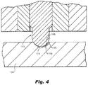
Fig. 4 is a schematic depiction of a cross-section of a portion of the fuel filter assembly ofFig. 1 , showing the electro-static discharge pin in contact with a side surface of the concave feature, but not in contact with the bottom most point of the concave feature. - Reference will now be made to the drawings wherein like reference numerals identify similar structural features or aspects of the subject disclosure. For purposes of explanation and illustration, and not limitation, a partial view of an exemplary embodiment of a fuel filter assembly in accordance with the disclosure is shown in
Fig. 1 and is designated generally byreference character 100. Other embodiments of fuel filter assemblies in accordance with the disclosure, or aspects thereof, are provided inFigs. 2A-4 , as will be described. The systems and methods described herein can be used for providing more efficient and effective cooling of transformer assemblies. - As shown in
Figs. 1-3 , afuel filter assembly 100 includes afilter bowl body 102 including abottom wall 104. Thebottom wall 104 has aconcave feature 106, e.g. a concave receiving indent. Thefuel filter assembly 100 includes an electro-static discharge (ESD)pin 108 at least partially positioned within in theconcave feature 106. Whileconcave feature 106 is shown as having a thickness less than the remaining portion ofbottom wall 104, those skilled in the art will readily appreciate thatconcave feature 106 can be formed by bending a portion ofbottom wall 104 outward, thereby still retaining a constant thickness with the remaining portions ofwall 104. Thisconcave feature 106 is able to better situate the pin 108 (as compared with traditional bottom walls that are typically flat) such that, even under a severe vibratory environment, theESD pin 108 and thefilter bowl body 102 will always be in contact, thus enabling the continuous bonding path for electrical discharge. - As shown in
Figs. 2B-3 , theESD pin 108 has afirst end 110 and asecond end 112. TheESD pin 108 defines a longitudinal axis A between thefirst end 110 and thesecond end 112. Thefirst end 110 includes aconvex tip 114 defining aconvex surface 116. A diameter D1 of theconcave feature 106 is larger than the diameter D2 of theconvex tip 114, for example, D1 of theconcave feature 106 is just big enough to receive theconvex tip 114. Theconvex surface 116 abuts aconcave surface 105 of theconcave feature 106. A shape of theconvex tip 114 conforms to theconcave feature 106. Any potentially accumulated electrical charges will be able to be dissipated through theESD pin 108 to filterbowl body 102. TheESD pin 108 thereby reduces or eliminates the risk of electrical charges resulting in an arc within thefilter bowl body 102, that could ignite fuel, or the like. Theconcave feature 106 acts to retainpin 108 through its concave shape and maintain electrical contact with theESD pin 108 for improved electrical charge dissipation. In particular, under vibratory conditions, theconcave feature 106 provides additional surface area for contact such that even if theESD pin 108 loses contact with the bottom most surface of theconcave feature 106, the sides of the concave feature can still maintain contact in some scenarios and thereby still dissipate electrical charges, as shown inFig. 4 . - As shown in
Fig. 3 , theassembly 100 includes afuel filter element 118 positioned in thefilter bowl body 102 having a generally cylindrical shape with open ends, e.g. an open cylinder shape. Thefilter bowl body 102 can be made from a metallic material, e.g. aluminum, with a non-conductive coating. Thefuel filter element 118 is positioned around theESD pin 108. Thefuel filter element 118 is a non-conductive material, such as fiber-glass. Fuel flow throughfilter 118 is shown schematically by arrows inFig. 3 . Those skilled in the art will readily appreciate, however, that fuel flow could flow from the outer diameter to the inner diameter offilter element 118. Thefuel filter element 118 terminates in abottom floor 126.Bottom floor 126 is annular shaped and extends from side walls offilter bowl body 102 and underneath thefuel filter element 118.Bottom floor 126 is made from a metallic material, e.g. aluminum. Theassembly 100 includes apin support member 120 operatively connected to thefuel filter element 118 and/or thefilter bowl body 102 via thebottom floor 126.Pin support member 120 andESD pin 108 provide a conductive path frombottom floor 126 tobottom wall 104 to avoid ESD accumulation. Bottom wall 1 04 ofbowl body 102 can be made from a metallic material, such as aluminum, or the like, and at least a portion ofbottom wall 104 can be coated with a conductive material to ensure a conductive path toESD pin 108. Thepin support member 120 includes anaperture 122 for receiving theESD pin 108. TheESD pin 108 is press-fit within theaperture 122 of thepin support member 120. - A method for discharging electro-static in a fuel filter assembly, e.g.
fuel filter assembly 100, includes providing a filter bowl body, e.g.filter bowl body 102. The filter bowl body includes a bottom wall, e.g.bottom wall 104. The bottom wall has a concave feature, e.g.concave feature 106. The method includes discharging electro-static by positioning an ESD pin,e.g. ESD pin 108, at least partially within the concave feature. Positioning the ESD pin includes positioning a convex surface, e.g.convex surface 116, to abut a concave surface, e.g.concave surface 105, of the concave feature. Providing the filter bowl body includes machining the concave feature into the bottom wall. The method includes providing a pin support member, e.g.pin support member 120. Positioning the ESD pin includes positioning the ESD pin within an aperture,e.g. aperture 122, of the pin support member. Positioning the ESD pin including press-fitting the ESD pin within the aperture of the pin support member. - The methods and systems of the present disclosure, as described above and shown in the drawings, provide for an improved receiving end on the fuel filter housing so that the ESD pin can be better situated, providing a more reliable conductive and continuous bonding path between the ESD pin and housing, even during severe vibratory environment. While the apparatus, assemblies and methods of the subject disclosure have been shown and described with reference to preferred embodiments, those skilled in the art will readily appreciate that changes and/or modifications may be made thereto without departing from the scope of the invention as defined by the claims.
Claims (15)
- A fuel filter assembly comprising:a filter bowl body (102) including a bottom wall (104), the bottom wall having a concave feature (106); andan electro-static discharge, ESD, pin (108) at least partially positioned within the concave feature.
- The assembly of claim 1, wherein the ESD pin has a first end (110) and a second end (112) and defines a longitudinal axis between the first end and the second end.
- The assembly of claim 2, wherein the first end includes a convex tip (114) defining a convex surface (116).
- The assembly of claim 3, wherein a diameter of the concave feature is larger than a diameter of the convex tip.
- The assembly of claim 3, wherein the convex surface abuts a concave surface (105) of the concave feature.
- The assembly of claim 3, wherein a shape of the convex tip conforms to the concave feature.
- The assembly of any preceding claim, further comprising a fuel filter element (118) positioned in the filter bowl body and/or wherein the fuel filter element is positioned around the ESD pin and/or further comprising a pin support member operatively connected to at least one of the fuel filter element or the filter bowl body, wherein the pin support member includes an aperture for receiving the ESD pin and preferably wherein the ESD pin is press-fit within the aperture of the pin support member.
- The assembly of claim 7, wherein the fuel filter element is a non-conductive material.
- The assembly of any preceding claim, wherein the filter bowl body is a metallic material.
- A method of making a fuel filter assembly that discharges electro-static during operation, the method including:providing a filter bowl body including a bottom wall, the bottom wall having a concave feature; andpositioning an electro-static discharge (ESD) pin at least partially within the concave feature to discharge electro-static during operation.
- The method of claim 10, wherein the ESD pin has a first end and a second end and defines a longitudinal axis between the first end and the second end.
- The method of claim 11, wherein the first end includes a convex tip defining a convex surface.
- The method of claim 12, wherein positioning the ESD pin includes positioning the convex surface to abut a concave surface of the concave feature.
- The method of any of claims 10 to 13, wherein providing the filter bowl body includes machining the concave feature into the bottom wall.
- The method of any of claims 10 to 14, further comprising providing a pin support member and preferably wherein positioning the ESD pin includes positioning the ESD pin within an aperture of the pin support member or wherein positioning the ESD pin includes press-fitting the ESD pin within the aperture of the pin support member.
Applications Claiming Priority (1)
| Application Number | Priority Date | Filing Date | Title |
|---|---|---|---|
| US16/592,238 US11473541B2 (en) | 2019-10-03 | 2019-10-03 | Fuel filter bowl assemblies |
Publications (1)
| Publication Number | Publication Date |
|---|---|
| EP3799942A1 true EP3799942A1 (en) | 2021-04-07 |
Family
ID=68762617
Family Applications (1)
| Application Number | Title | Priority Date | Filing Date |
|---|---|---|---|
| EP19212888.2A Pending EP3799942A1 (en) | 2019-10-03 | 2019-12-02 | Fuel filter bowl assemblies |
Country Status (2)
| Country | Link |
|---|---|
| US (1) | US11473541B2 (en) |
| EP (1) | EP3799942A1 (en) |
Citations (3)
| Publication number | Priority date | Publication date | Assignee | Title |
|---|---|---|---|---|
| US8182682B1 (en) * | 2011-02-25 | 2012-05-22 | Pall Corporation | Fluid treatment elements and assemblies |
| US20170276106A1 (en) * | 2016-03-23 | 2017-09-28 | Ufi Filters (Shanghai) Co., Ltd. | Fuel filter |
| WO2018234633A1 (en) * | 2017-06-19 | 2018-12-27 | Lifa Air Ltd | Electrical filter structure |
Family Cites Families (2)
| Publication number | Priority date | Publication date | Assignee | Title |
|---|---|---|---|---|
| US3262570A (en) * | 1963-02-05 | 1966-07-26 | Commercial Filter Corp | Filtration assemblies and replaceable elements of such assemblies |
| US6740236B2 (en) * | 2001-09-25 | 2004-05-25 | Kuss Corporation | Fuel filter assembly having a conductive spring |
-
2019
- 2019-10-03 US US16/592,238 patent/US11473541B2/en active Active
- 2019-12-02 EP EP19212888.2A patent/EP3799942A1/en active Pending
Patent Citations (3)
| Publication number | Priority date | Publication date | Assignee | Title |
|---|---|---|---|---|
| US8182682B1 (en) * | 2011-02-25 | 2012-05-22 | Pall Corporation | Fluid treatment elements and assemblies |
| US20170276106A1 (en) * | 2016-03-23 | 2017-09-28 | Ufi Filters (Shanghai) Co., Ltd. | Fuel filter |
| WO2018234633A1 (en) * | 2017-06-19 | 2018-12-27 | Lifa Air Ltd | Electrical filter structure |
Also Published As
| Publication number | Publication date |
|---|---|
| US20210102519A1 (en) | 2021-04-08 |
| US11473541B2 (en) | 2022-10-18 |
Similar Documents
| Publication | Publication Date | Title |
|---|---|---|
| US5918571A (en) | Dual electrode high thread spark plug | |
| US4093529A (en) | Resistor anode for metal tank | |
| WO1997030497A1 (en) | Spark plug with integral retainer nut | |
| KR960003005A (en) | Spark plugs for internal combustion engines | |
| EP1102373A3 (en) | Spark plug | |
| DE602005004832T2 (en) | spark plug | |
| RU2577319C2 (en) | Ice spark-plug | |
| WO1999019953A1 (en) | A radial gap high thread spark plug | |
| US11473541B2 (en) | Fuel filter bowl assemblies | |
| US4461530A (en) | Socket contact for electrical connectors and method of manufacture | |
| CN104466683B (en) | Corona ignition device | |
| US7243643B2 (en) | Ignition device for internal combustion engine | |
| US10256610B2 (en) | Spark plug | |
| JPH0656777B2 (en) | Socket contact device with closed outlet | |
| EP1603207A2 (en) | Gas filled switching electric discharge tube | |
| US3056899A (en) | Spark plug adapter | |
| US7768183B2 (en) | Extension spark plug | |
| US10707653B2 (en) | Spark plug | |
| US10989686B2 (en) | Gas sensor | |
| US8221144B1 (en) | Partial discharge resistant connector | |
| US9941672B2 (en) | Corona ignition device and method for the production thereof | |
| JP7470068B2 (en) | Capacitor Device | |
| US1352089A (en) | Spark-plug | |
| EP0480886A1 (en) | A spark plug | |
| EP4604148A1 (en) | Ignition coil |
Legal Events
| Date | Code | Title | Description |
|---|---|---|---|
| PUAI | Public reference made under article 153(3) epc to a published international application that has entered the european phase |
Free format text: ORIGINAL CODE: 0009012 |
|
| STAA | Information on the status of an ep patent application or granted ep patent |
Free format text: STATUS: THE APPLICATION HAS BEEN PUBLISHED |
|
| AK | Designated contracting states |
Kind code of ref document: A1 Designated state(s): AL AT BE BG CH CY CZ DE DK EE ES FI FR GB GR HR HU IE IS IT LI LT LU LV MC MK MT NL NO PL PT RO RS SE SI SK SM TR |
|
| AX | Request for extension of the european patent |
Extension state: BA ME |
|
| STAA | Information on the status of an ep patent application or granted ep patent |
Free format text: STATUS: REQUEST FOR EXAMINATION WAS MADE |
|
| 17P | Request for examination filed |
Effective date: 20211007 |
|
| RBV | Designated contracting states (corrected) |
Designated state(s): AL AT BE BG CH CY CZ DE DK EE ES FI FR GB GR HR HU IE IS IT LI LT LU LV MC MK MT NL NO PL PT RO RS SE SI SK SM TR |
|
| STAA | Information on the status of an ep patent application or granted ep patent |
Free format text: STATUS: EXAMINATION IS IN PROGRESS |
|
| 17Q | First examination report despatched |
Effective date: 20221028 |
|
| GRAP | Despatch of communication of intention to grant a patent |
Free format text: ORIGINAL CODE: EPIDOSNIGR1 |
|
| STAA | Information on the status of an ep patent application or granted ep patent |
Free format text: STATUS: GRANT OF PATENT IS INTENDED |
|
| INTG | Intention to grant announced |
Effective date: 20260311 |