EP3799423A1 - Non-uniformity correction for focal plane arrays - Google Patents
Non-uniformity correction for focal plane arrays Download PDFInfo
- Publication number
- EP3799423A1 EP3799423A1 EP20197422.7A EP20197422A EP3799423A1 EP 3799423 A1 EP3799423 A1 EP 3799423A1 EP 20197422 A EP20197422 A EP 20197422A EP 3799423 A1 EP3799423 A1 EP 3799423A1
- Authority
- EP
- European Patent Office
- Prior art keywords
- graybody
- fpa
- imaging
- nuc
- data
- Prior art date
- Legal status (The legal status is an assumption and is not a legal conclusion. Google has not performed a legal analysis and makes no representation as to the accuracy of the status listed.)
- Granted
Links
Images

Classifications
-
- G—PHYSICS
- G01—MEASURING; TESTING
- G01J—MEASUREMENT OF INTENSITY, VELOCITY, SPECTRAL CONTENT, POLARISATION, PHASE OR PULSE CHARACTERISTICS OF INFRARED, VISIBLE OR ULTRAVIOLET LIGHT; COLORIMETRY; RADIATION PYROMETRY
- G01J5/00—Radiation pyrometry, e.g. infrared or optical thermometry
- G01J5/52—Radiation pyrometry, e.g. infrared or optical thermometry using comparison with reference sources, e.g. disappearing-filament pyrometer
- G01J5/53—Reference sources, e.g. standard lamps; Black bodies
-
- H—ELECTRICITY
- H04—ELECTRIC COMMUNICATION TECHNIQUE
- H04N—PICTORIAL COMMUNICATION, e.g. TELEVISION
- H04N25/00—Circuitry of solid-state image sensors [SSIS]; Control thereof
- H04N25/60—Noise processing, e.g. detecting, correcting, reducing or removing noise
- H04N25/67—Noise processing, e.g. detecting, correcting, reducing or removing noise applied to fixed-pattern noise, e.g. non-uniformity of response
- H04N25/671—Noise processing, e.g. detecting, correcting, reducing or removing noise applied to fixed-pattern noise, e.g. non-uniformity of response for non-uniformity detection or correction
- H04N25/673—Noise processing, e.g. detecting, correcting, reducing or removing noise applied to fixed-pattern noise, e.g. non-uniformity of response for non-uniformity detection or correction by using reference sources
-
- G—PHYSICS
- G01—MEASURING; TESTING
- G01J—MEASUREMENT OF INTENSITY, VELOCITY, SPECTRAL CONTENT, POLARISATION, PHASE OR PULSE CHARACTERISTICS OF INFRARED, VISIBLE OR ULTRAVIOLET LIGHT; COLORIMETRY; RADIATION PYROMETRY
- G01J5/00—Radiation pyrometry, e.g. infrared or optical thermometry
- G01J5/02—Constructional details
- G01J5/027—Constructional details making use of sensor-related data, e.g. for identification of sensor parts or optical elements
-
- H—ELECTRICITY
- H04—ELECTRIC COMMUNICATION TECHNIQUE
- H04N—PICTORIAL COMMUNICATION, e.g. TELEVISION
- H04N17/00—Diagnosis, testing or measuring for television systems or their details
- H04N17/002—Diagnosis, testing or measuring for television systems or their details for television cameras
-
- H—ELECTRICITY
- H04—ELECTRIC COMMUNICATION TECHNIQUE
- H04N—PICTORIAL COMMUNICATION, e.g. TELEVISION
- H04N23/00—Cameras or camera modules comprising electronic image sensors; Control thereof
- H04N23/20—Cameras or camera modules comprising electronic image sensors; Control thereof for generating image signals from infrared radiation only
- H04N23/23—Cameras or camera modules comprising electronic image sensors; Control thereof for generating image signals from infrared radiation only from thermal infrared radiation
-
- G—PHYSICS
- G01—MEASURING; TESTING
- G01J—MEASUREMENT OF INTENSITY, VELOCITY, SPECTRAL CONTENT, POLARISATION, PHASE OR PULSE CHARACTERISTICS OF INFRARED, VISIBLE OR ULTRAVIOLET LIGHT; COLORIMETRY; RADIATION PYROMETRY
- G01J5/00—Radiation pyrometry, e.g. infrared or optical thermometry
- G01J2005/0077—Imaging
Definitions
- the present disclosure relates to imagery, and more particularly to non-uniformity correction for image sensors such as thermal imaging focal plane arrays (FPAs).
- FPAs thermal imaging focal plane arrays
- Thermal imaging FPAs have an inherent amount of non-uniformity from pixel to pixel.
- Traditional non-uniformity correction requires uniform illumination of all pixels with each of two different optical irradiance levels.
- a linear transformation based on the two known irradiance levels can be used to make all the pixels read uniformly, canceling out non-uniformity.
- the conventional approach uses blackbodies at two different temperatures to provide the two different irradiance levels needed. NUC needs to be performed periodically in order to keep the pixels reading uniformly.
- one blackbody can be used to obtain the blackbody calibration at a first temperature, and the sensor can be oriented at the outside view to obtain simulated blackbody irradiance at the ambient temperature. Since the outside view is not always at a significantly different temperature from the blackbody at the first temperature, and this cannot be controlled, this technique for airborne FPAs is limited in effectiveness.
- a method includes imaging a first graybody with a focal plane array (FPA), wherein the first graybody has a first emissivity, and imaging a second graybody having a lower emissivity than the first graybody.
- the method includes using data captured while imaging the first and second graybodies to perform non-uniformity correction (NUC) of the FPA.
- NUC non-uniformity correction
- Imaging the first and second graybodies can include imaging each of the first and second graybodies with the first and second graybodies at the same temperature.
- the first graybody can be a blackbody.
- the second graybody can include a surface coated with a coating that provides less angular sensitivity than a specular mirror in a waveband of the FPA.
- the FPA can be sensitive to thermal infrared, and wherein imaging the first graybody and the second graybody can be performed at a temperature at which blackbody radiation peaks in the thermal infrared. Imaging the first graybody and imaging the second graybody can be performed without temperature controlling the first graybody or second graybody.
- the first graybody can be located inside a pod at a first angular position, wherein the second graybody is located inside the pod at a second angular position, and wherein imaging the first graybody includes rotating the FPA to orient the FPA toward the first graybody, and wherein imaging the second graybody includes rotating the FPA to orient the FPA toward the second graybody.
- the method can include rotating the FPA to face a scene outside the pod after performing NUC.
- the method can include periodically repeating imaging the first graybody, imaging the second graybody, and performing NUC of the FPA in flight.
- NUC can be performed in flight for an airborne imaging platform, wherein the NUC is in addition to a one-time calibration of the FPA that transforms raw sensor data from the FPA to a flat signal canceling low-frequency pixel to pixel variation.
- the one-time calibration of the FPA can be configured to provide calibration data to remove low-frequency rolloff in the FPA resulting from using the second graybody for NUC.
- the one-time calibration can include imaging a test graybody with the FPA to produce low-E data, subtracting a dark frame from the low-E data to produce low-E dark subtracted data, wherein the dark frame is representative of the FPA's dark current, imaging a test blackbody with the FPA to product blackbody data, subtracting the dark frame from the blackbody data to produce blackbody dark subtracted data, fitting a first polynomial to the low-E dark subtracted data, fitting a second polynomial to the blackbody dark subtracted data, and scaling each column of the low-E dark subtracted data by a ratio of the first and second polynomials to produce calibration data, and saving the calibration data for use in NUC.
- Imaging the test graybody can be performed with the test graybody at 36 °C
- imaging the test blackbody can be performed with the test blackbody at 1 °C.
- a system includes a first graybody and a second graybody having lower emissivity than the first graybody, wherein the first graybody and second graybody are operatively connected to be at the same temperature.
- a focal plane array (FPA) is operatively connected to the first graybody and to the second graybody.
- a controller is operatively connected to the FPA to direct the FPA toward the first graybody to image the first graybody, and to direct the FPA toward the second graybody to image the second graybody, to perform non-uniformity correction (NUC) on the FPA based on data from imaging the first graybody and second graybody, and to capture image data from the FPA after NUC.
- NUC non-uniformity correction
- the second graybody can include a surface coated with a coating that provides less angular sensitivity than a specular mirror in a waveband of the FPA.
- the FPA can be sensitive to thermal infrared.
- the first graybody can be located inside a pod at a first angular position, wherein the second graybody is located inside the pod at a second angular position, and wherein the controller is configured to rotate the FPA to orient the FPA toward the first graybody for imaging the first graybody, and to rotate the FPA to orient the FPA toward the second graybody for imaging the second graybody.
- the controller can be configured to rotate the FPA to face a scene outside the pod after performing NUC.
- the controller is configured to perform NUC in flight for an airborne imaging platform.
- the controller can be configured to periodically repeat imaging the first graybody, imaging the second graybody, and NUC of the FPA in flight.
- the first graybody can be a blackbody.
- the controller can include calibration data configured to remove low-frequency rolloff in the FPA resulting from using the second graybody for NUC.
- Fig. 1 a partial view of an embodiment of a system in accordance with the disclosure is shown in Fig. 1 and is designated generally by reference character 100.
- Other embodiments of systems in accordance with the disclosure, or aspects thereof, are provided in Figs. 2-4 , as will be described.
- the systems and methods described herein can be used to provide non-uniformity correction (NUC) for focal plane arrays (FPAs) such as thermal imaging FPAs.
- NUC non-uniformity correction
- FPAs focal plane arrays
- thermal imaging FPAs thermal imaging
- the system 100 includes a first graybody 102 and a second graybody 104 having lower emissivity than the first graybody.
- a focal plane array (FPA) 106 is operatively connected to the first graybody 102 and to the second graybody NUC.
- FPA focal plane array
- a controller 108 is operatively connected to the FPA 106 move the FPA 106 to direct the FPA 106 toward the first graybody 102 to image the first graybody 102, and to direct the FPA 106 toward the second graybody 104 to image the second graybody 104, and to perform non-uniformity correction (NUC) on the FPA 106 based on data from imaging the first graybody 102 and second graybody 104.
- the controller 108 is also configured to use the FPA 106 capture image data from the FPA 106 after NUC.
- the first graybody 102 can be a blackbody.
- a blackbody is a species of the genus of graybodies, or in other words a blackbody is a graybody with an emissivity of unity (1.0) or near enough to unity for practical applications.
- the first graybody 102 and second graybody 104 are operatively connected within a pod 110 so as to be at the same temperature as one another, or to be near enough to the same temperature with each other for practical implantation of techniques disclosed herein. It is also contemplated that the two graybodies 102, 104 can be at different temperatures.
- the second graybody 104 includes a surface coated with a coating that provides less angular sensitivity than a specular mirror in a waveband of the FPA, and that provides graybody emissivity lower than the emissivity of the first graybody 102. Using a specular mirror would let the pixels in the FPA 106 "see" themselves at the cooled temperature inside a Dewar, but that is very angular sensitive.
- the FPA can be sensitive to thermal infrared, i.e. for thermal IR imagery.
- the first graybody 102 is located inside the pod 100 at an angular position aligned along an axis A.
- the second graybody 104 is located inside the pod 110 at different angular position aligned along an axis B.
- the controller 108 is configured to rotate the FPA 106 (e.g. by controlling the gimbal 112) to orient the FPA 106 toward the first graybody 102 for imaging the first graybody 102 (as shown in Fig. 2 ), and to rotate the FPA to orient the FPA 106 toward the second graybody 104 (as shown in Fig. 3 ) for imaging the second graybody 104.
- the controller 108 is also configured to rotate the FPA 106 to face a scene outside the pod 110 after performing NUC, e. aligning the FPA 106 along the axis C or any other axis for viewing external from the pod 110.
- the controller 108 is configured to perform NUC in flight for an airborne imaging platform, e.g., wherein the pod 110 is mounted to an airborne platform 111.
- the controller 108 can be configured to periodically repeat imaging the first graybody 102, imaging the second graybody 104, and performing NUC of the FPA 106 in flight.
- the controller 106 can include calibration data configured to remove low-frequency rolloff in the FPA 106 resulting from using the second graybody 104 for NUC instead of using a blackbody for both irradiance levels in NUC.
- a method includes imaging the first graybody 102 with the FPA 106, wherein the first graybody has a first emissivity and is at a first temperature.
- the method includes imaging the second graybody 104, which simulates a blackbody having a lower temperature than the first graybody 102 even though the second graybody 104 is at the same temperature as the first graybody 102. This is because the second graybody 104 has a lower emissivity than the first graybody 102.
- the method includes using data captured while imaging the first and second graybodies 102 and 104 to perform non-uniformity correction (NUC) of the FPA. Imaging the first graybody 102 and the second graybody 104 can both be performed at a temperature at which blackbody radiation peaks in the thermal infrared.
- NUC non-uniformity correction
- Imaging the first graybody 102 and imaging the second graybody 104 can be performed without temperature controlling the first graybody 102 or second graybody 104.
- Imaging the first graybody 102 includes rotating the FPA 106 to orient the FPA 106 toward the first graybody 102 as shown in Fig. 2 .
- Imaging the second graybody 104 includes rotating the FPA 106 to orient the FPA 106 toward the second graybody 104 as shown in Fig. 3 .
- the method can include rotating the FPA 106 to face a scene outside the pod after performing NUC, as shown in Fig. 1 .
- the method can include periodically repeating imaging the first graybody 102, imaging the second graybody 104, and performing NUC of the FPA 106 in flight.
- NUC can be performed in flight for an airborne imaging platform (e.g., wherein the pod 110 is mounted to an airborne platform 111).
- the NUC described above is in addition to a one-time calibration of the FPA 106 that transforms raw sensor data from the FPA 106 to a flat signal canceling low-frequency pixel to pixel variation.
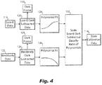
- the one-time calibration of the FPA 106 is configured to provide calibration data (as indicated in Fig. 4 with box 114) to remove low-frequency rolloff in the FPA 106 that results from using the second graybody 104 for NUC. Low-frequency in this sense is quantified relative to the relatively high frequency of the nonuniform raw sensor data from the FPA 106.
- the one-time calibration can include imaging a test graybody with the FPA to produce low-E data as indicated in Fig, 4 with box 116, and subtracting a dark frame (indicated in Fig. 4 with box 118) from the low-E data to produce low-E dark subtracted data as indicated in Fig. 4 with box 120, wherein the dark frame is representative of the dark current of the FPA 106.
- the calibration includes imaging a test blackbody with the FPA 106 to product blackbody data (as indicated in Fig. 4 with box 122) and subtracting the dark frame (indicated in Fig. 4 by box 124, which is the same dark frame indicated by box 118) from the blackbody data to produce blackbody dark subtracted data as indicated in Fig. 4 by box 126.
- the calibration includes fitting a first polynomial to the low-E dark subtracted data (as indicated in Fig. 4 by box 128 and fitting a second polynomial to the blackbody dark subtracted data (as indicated in Fig. 4 by the box 130).
- the calibration includes scaling each column (representing a column of pixels in the FPA 106) of the low-E dark subtracted data 120 by a ratio of the first and second polynomials (in boxes 128 and 130) to produce calibration data as indicated by box 132, and saving the calibration data for use in NUC as indicated in box 114.
- Imaging the test graybody can be performed with the test graybody at 36 °C
- imaging the test blackbody can be performed with the test blackbody at 1 °C.
- any other temperatures with a suitably large difference can be used.
- the dark subtraction and ratio is not necessary when the surface characteristics are the same for the blackbody or graybody sources.
- the reason for using the low-E surface is that the surface reflectance characteristics of the low-E surface are very different from the black body source.
- the polynomial fitting for reducing/eliminating low-frequency rolloff may not be needed in some applications, e.g., depending on the sensor configuration.
- imaging in this context does not require forming a focused image on a sensor.
- the graybodies can be positioned closer than the minimum focusing distance without departing from the scope of this disclosure.
- calibration in this context is not to be confused with the process of creating NUC coefficients to be applied to the pixels or applying the NUC coefficients.
Landscapes
- Engineering & Computer Science (AREA)
- Multimedia (AREA)
- Signal Processing (AREA)
- Health & Medical Sciences (AREA)
- Physics & Mathematics (AREA)
- General Physics & Mathematics (AREA)
- Spectroscopy & Molecular Physics (AREA)
- Toxicology (AREA)
- Biomedical Technology (AREA)
- General Health & Medical Sciences (AREA)
- Radiation Pyrometers (AREA)
- Photometry And Measurement Of Optical Pulse Characteristics (AREA)
Abstract
Description
- The present disclosure relates to imagery, and more particularly to non-uniformity correction for image sensors such as thermal imaging focal plane arrays (FPAs).
- Thermal imaging FPAs have an inherent amount of non-uniformity from pixel to pixel. Traditional non-uniformity correction (NUC) requires uniform illumination of all pixels with each of two different optical irradiance levels. A linear transformation based on the two known irradiance levels can be used to make all the pixels read uniformly, canceling out non-uniformity. The conventional approach uses blackbodies at two different temperatures to provide the two different irradiance levels needed. NUC needs to be performed periodically in order to keep the pixels reading uniformly. In airborne applications, one blackbody can be used to obtain the blackbody calibration at a first temperature, and the sensor can be oriented at the outside view to obtain simulated blackbody irradiance at the ambient temperature. Since the outside view is not always at a significantly different temperature from the blackbody at the first temperature, and this cannot be controlled, this technique for airborne FPAs is limited in effectiveness.
- The conventional techniques have been considered satisfactory for their intended purpose. However, there is an ever present need for improved systems and methods for non-uniformity correction for FPAs. This disclosure provides a solution for this need.
- A method includes imaging a first graybody with a focal plane array (FPA), wherein the first graybody has a first emissivity, and imaging a second graybody having a lower emissivity than the first graybody. The method includes using data captured while imaging the first and second graybodies to perform non-uniformity correction (NUC) of the FPA.
- Imaging the first and second graybodies can include imaging each of the first and second graybodies with the first and second graybodies at the same temperature. The first graybody can be a blackbody. The second graybody can include a surface coated with a coating that provides less angular sensitivity than a specular mirror in a waveband of the FPA. The FPA can be sensitive to thermal infrared, and wherein imaging the first graybody and the second graybody can be performed at a temperature at which blackbody radiation peaks in the thermal infrared. Imaging the first graybody and imaging the second graybody can be performed without temperature controlling the first graybody or second graybody.
- The first graybody can be located inside a pod at a first angular position, wherein the second graybody is located inside the pod at a second angular position, and wherein imaging the first graybody includes rotating the FPA to orient the FPA toward the first graybody, and wherein imaging the second graybody includes rotating the FPA to orient the FPA toward the second graybody. The method can include rotating the FPA to face a scene outside the pod after performing NUC. The method can include periodically repeating imaging the first graybody, imaging the second graybody, and performing NUC of the FPA in flight.
- NUC can be performed in flight for an airborne imaging platform, wherein the NUC is in addition to a one-time calibration of the FPA that transforms raw sensor data from the FPA to a flat signal canceling low-frequency pixel to pixel variation. The one-time calibration of the FPA can be configured to provide calibration data to remove low-frequency rolloff in the FPA resulting from using the second graybody for NUC. The one-time calibration can include imaging a test graybody with the FPA to produce low-E data, subtracting a dark frame from the low-E data to produce low-E dark subtracted data, wherein the dark frame is representative of the FPA's dark current, imaging a test blackbody with the FPA to product blackbody data, subtracting the dark frame from the blackbody data to produce blackbody dark subtracted data, fitting a first polynomial to the low-E dark subtracted data, fitting a second polynomial to the blackbody dark subtracted data, and scaling each column of the low-E dark subtracted data by a ratio of the first and second polynomials to produce calibration data, and saving the calibration data for use in NUC. Imaging the test graybody can be performed with the test graybody at 36 °C, and imaging the test blackbody can be performed with the test blackbody at 1 °C.
- A system includes a first graybody and a second graybody having lower emissivity than the first graybody, wherein the first graybody and second graybody are operatively connected to be at the same temperature. A focal plane array (FPA) is operatively connected to the first graybody and to the second graybody. A controller is operatively connected to the FPA to direct the FPA toward the first graybody to image the first graybody, and to direct the FPA toward the second graybody to image the second graybody, to perform non-uniformity correction (NUC) on the FPA based on data from imaging the first graybody and second graybody, and to capture image data from the FPA after NUC.
- The second graybody can include a surface coated with a coating that provides less angular sensitivity than a specular mirror in a waveband of the FPA. The FPA can be sensitive to thermal infrared. The first graybody can be located inside a pod at a first angular position, wherein the second graybody is located inside the pod at a second angular position, and wherein the controller is configured to rotate the FPA to orient the FPA toward the first graybody for imaging the first graybody, and to rotate the FPA to orient the FPA toward the second graybody for imaging the second graybody. The controller can be configured to rotate the FPA to face a scene outside the pod after performing NUC. The controller is configured to perform NUC in flight for an airborne imaging platform. The controller can be configured to periodically repeat imaging the first graybody, imaging the second graybody, and NUC of the FPA in flight. The first graybody can be a blackbody. The controller can include calibration data configured to remove low-frequency rolloff in the FPA resulting from using the second graybody for NUC.
- While shown and described herein in the context of an airborne platform, those skilled in the art will readily appreciate that systems and methods as disclosed herein can readily be implemented in any suitable type of platform such as spaceborne, ground telescopes, hand held night scopes on rifles, ground vehicle mounted, or boat mounted without departing from the scope of this disclosure.
- These and other features of the systems and methods of the subject disclosure will become more readily apparent to those skilled in the art from the following detailed description of the preferred embodiments taken in conjunction with the drawings.
- So that those skilled in the art to which the subject disclosure appertains will readily understand how to make and use the devices and methods of the subject disclosure without undue experimentation, preferred embodiments thereof will be described in detail herein below with reference to certain figures, wherein:
-
Fig. 1 is a schematic view of an embodiment of a system constructed in accordance with the present disclosure, showing the focal plane array (FPA) directed outside the pod for imaging an external scene; -
Fig. 2 is a schematic view of the system ofFig. 1 , showing the FPA directed toward a first graybody within the pod; -
Fig. 3 is a schematic view of the system ofFig. 1 , showing the FPA directed toward a second gray body within the pod; and -
Fig. 4 is a diagram of an exemplary embodiment of a process for calibration of the system ofFig. 1 . - Reference will now be made to the drawings wherein like reference numerals identify similar structural features or aspects of the subject disclosure. For purposes of explanation and illustration, and not limitation, a partial view of an embodiment of a system in accordance with the disclosure is shown in
Fig. 1 and is designated generally byreference character 100. Other embodiments of systems in accordance with the disclosure, or aspects thereof, are provided inFigs. 2-4 , as will be described. The systems and methods described herein can be used to provide non-uniformity correction (NUC) for focal plane arrays (FPAs) such as thermal imaging FPAs. - The
system 100 includes afirst graybody 102 and asecond graybody 104 having lower emissivity than the first graybody. A focal plane array (FPA) 106 is operatively connected to thefirst graybody 102 and to the second graybody NUC. Those skilled in the art will readily appreciate that there can optionally be a lens in front of the FPA 106 for optically coupling the FPA to the first and secondgray bodies controller 108 is operatively connected to the FPA 106 move the FPA 106 to direct the FPA 106 toward thefirst graybody 102 to image thefirst graybody 102, and to direct theFPA 106 toward thesecond graybody 104 to image thesecond graybody 104, and to perform non-uniformity correction (NUC) on the FPA 106 based on data from imaging thefirst graybody 102 andsecond graybody 104. Thecontroller 108 is also configured to use the FPA 106 capture image data from the FPA 106 after NUC. Thefirst graybody 102 can be a blackbody. As used herein, a blackbody is a species of the genus of graybodies, or in other words a blackbody is a graybody with an emissivity of unity (1.0) or near enough to unity for practical applications. - The
first graybody 102 andsecond graybody 104 are operatively connected within apod 110 so as to be at the same temperature as one another, or to be near enough to the same temperature with each other for practical implantation of techniques disclosed herein. It is also contemplated that the twograybodies second graybody 104 includes a surface coated with a coating that provides less angular sensitivity than a specular mirror in a waveband of the FPA, and that provides graybody emissivity lower than the emissivity of thefirst graybody 102. Using a specular mirror would let the pixels in the FPA 106 "see" themselves at the cooled temperature inside a Dewar, but that is very angular sensitive. The FPA can be sensitive to thermal infrared, i.e. for thermal IR imagery. Thefirst graybody 102 is located inside thepod 100 at an angular position aligned along an axis A. Thesecond graybody 104 is located inside thepod 110 at different angular position aligned along an axis B. Thecontroller 108 is configured to rotate the FPA 106 (e.g. by controlling the gimbal 112) to orient theFPA 106 toward thefirst graybody 102 for imaging the first graybody 102 (as shown inFig. 2 ), and to rotate the FPA to orient theFPA 106 toward the second graybody 104 (as shown inFig. 3 ) for imaging thesecond graybody 104. Thecontroller 108 is also configured to rotate theFPA 106 to face a scene outside thepod 110 after performing NUC, e. aligning theFPA 106 along the axis C or any other axis for viewing external from thepod 110. Thecontroller 108 is configured to perform NUC in flight for an airborne imaging platform, e.g., wherein thepod 110 is mounted to anairborne platform 111. Thecontroller 108 can be configured to periodically repeat imaging thefirst graybody 102, imaging thesecond graybody 104, and performing NUC of theFPA 106 in flight. Thecontroller 106 can include calibration data configured to remove low-frequency rolloff in theFPA 106 resulting from using thesecond graybody 104 for NUC instead of using a blackbody for both irradiance levels in NUC. - A method includes imaging the
first graybody 102 with theFPA 106, wherein the first graybody has a first emissivity and is at a first temperature. The method includes imaging thesecond graybody 104, which simulates a blackbody having a lower temperature than thefirst graybody 102 even though thesecond graybody 104 is at the same temperature as thefirst graybody 102. This is because thesecond graybody 104 has a lower emissivity than thefirst graybody 102. The method includes using data captured while imaging the first andsecond graybodies first graybody 102 and thesecond graybody 104 can both be performed at a temperature at which blackbody radiation peaks in the thermal infrared. Imaging thefirst graybody 102 and imaging thesecond graybody 104 can be performed without temperature controlling thefirst graybody 102 orsecond graybody 104. Imaging thefirst graybody 102 includes rotating theFPA 106 to orient theFPA 106 toward thefirst graybody 102 as shown inFig. 2 . Imaging thesecond graybody 104 includes rotating theFPA 106 to orient theFPA 106 toward thesecond graybody 104 as shown inFig. 3 . The method can include rotating theFPA 106 to face a scene outside the pod after performing NUC, as shown inFig. 1 . The method can include periodically repeating imaging thefirst graybody 102, imaging thesecond graybody 104, and performing NUC of theFPA 106 in flight. NUC can be performed in flight for an airborne imaging platform (e.g., wherein thepod 110 is mounted to an airborne platform 111). - With reference now to
Fig. 4 , the NUC described above is in addition to a one-time calibration of theFPA 106 that transforms raw sensor data from theFPA 106 to a flat signal canceling low-frequency pixel to pixel variation. The one-time calibration of theFPA 106 is configured to provide calibration data (as indicated inFig. 4 with box 114) to remove low-frequency rolloff in theFPA 106 that results from using thesecond graybody 104 for NUC. Low-frequency in this sense is quantified relative to the relatively high frequency of the nonuniform raw sensor data from theFPA 106. The one-time calibration can include imaging a test graybody with the FPA to produce low-E data as indicated inFig, 4 withbox 116, and subtracting a dark frame (indicated inFig. 4 with box 118) from the low-E data to produce low-E dark subtracted data as indicated inFig. 4 withbox 120, wherein the dark frame is representative of the dark current of theFPA 106. The calibration includes imaging a test blackbody with theFPA 106 to product blackbody data (as indicated inFig. 4 with box 122) and subtracting the dark frame (indicated inFig. 4 bybox 124, which is the same dark frame indicated by box 118) from the blackbody data to produce blackbody dark subtracted data as indicated inFig. 4 bybox 126. The calibration includes fitting a first polynomial to the low-E dark subtracted data (as indicated inFig. 4 bybox 128 and fitting a second polynomial to the blackbody dark subtracted data (as indicated inFig. 4 by the box 130). The calibration includes scaling each column (representing a column of pixels in the FPA 106) of the low-E dark subtracteddata 120 by a ratio of the first and second polynomials (inboxes 128 and 130) to produce calibration data as indicated bybox 132, and saving the calibration data for use in NUC as indicated inbox 114. Imaging the test graybody can be performed with the test graybody at 36 °C, and imaging the test blackbody can be performed with the test blackbody at 1 °C. Any other temperatures with a suitably large difference can be used. The dark subtraction and ratio is not necessary when the surface characteristics are the same for the blackbody or graybody sources. The reason for using the low-E surface is that the surface reflectance characteristics of the low-E surface are very different from the black body source. - Those skilled in the art will readily appreciate that the polynomial fitting for reducing/eliminating low-frequency rolloff may not be needed in some applications, e.g., depending on the sensor configuration. Those skilled in the art will also readily appreciate that imaging in this context does not require forming a focused image on a sensor. For example, the graybodies can be positioned closer than the minimum focusing distance without departing from the scope of this disclosure. Those skilled in the art will readily appreciate that calibration in this context is not to be confused with the process of creating NUC coefficients to be applied to the pixels or applying the NUC coefficients.
- The methods and systems of the present disclosure, as described above and shown in the drawings, provide for NUC with improved performance given potentially reduced cost and weight, e.g. for airborne sensor systems. While the apparatus and methods of the subject disclosure have been shown and described with reference to preferred embodiments, those skilled in the art will readily appreciate that changes and/or modifications may be made thereto without departing from the scope of the subject disclosure.
Claims (15)
- A method comprising:imaging a first graybody with a focal plane array (FPA), wherein the first graybody has a first emissivity;imaging a second graybody having a lower emissivity than the first graybody; andusing data captured while imaging the first and second graybodies to perform non-uniformity correction (NUC) of the FPA.
- The method as recited in claim 1, wherein imaging the first and second graybodies includes imaging each of the first and second graybodies with the first and second graybodies at the same temperature.
- The method as recited in claim 1 or 2, wherein the second graybody includes a surface coated with a coating that provides less angular sensitivity than a specular mirror in a waveband of the FPA.
- The method as recited in any preceding claim, wherein the FPA is sensitive to thermal infrared, and wherein imaging the first graybody and the second graybody are performed at a temperature at which blackbody radiation peaks in the thermal infrared.
- The method as recited in any preceding claim, wherein imaging the first graybody and imaging the second graybody are performed without temperature controlling the first graybody or second graybody.
- The method as recited in any preceding claim, wherein the first graybody is located inside a pod at a first angular position, wherein the second graybody is located inside the pod at a second angular position, and wherein imaging the first graybody includes rotating the FPA to orient the FPA toward the first graybody, and wherein imaging the second graybody includes rotating the FPA to orient the FPA toward the second graybody.
- The method as recited in claim 6, further comprising rotating the FPA to face a scene outside the pod after performing NUC; and/or further comprising periodically repeating imaging the first graybody, imaging the second graybody, and performing NUC of the FPA in flight..
- The method as recited in claim 6, wherein NUC is performed in flight for an airborne imaging platform, wherein the NUC is in addition to a one-time calibration of the FPA that transforms raw sensor data from the FPA to a flat signal canceling low-frequency pixel to pixel variation; and preferably wherein the one-time calibration of the FPA is configured to provide calibration data to remove low-frequency rolloff in the FPA resulting from using the second graybody for NUC, wherein the one-time calibration includes:imaging a test graybody with the FPA to produce low-E data;subtracting a dark frame from the low-E data to produce low-E dark subtracted data, wherein the dark frame is representative of the FPA's dark current;imaging a test blackbody with the FPA to product blackbody data;subtracting the dark frame from the blackbody data to produce blackbody dark subtracted data;fitting a first polynomial to the low-E dark subtracted data;fitting a second polynomial to the blackbody dark subtracted data; andscaling each column of the low-E dark subtracted data by a ratio of the first and second polynomials to produce calibration data, and saving the calibration data for use in NUC; and more preferably wherein imaging the test graybody is performed with the test graybody at 36 °C, and wherein imaging the test blackbody is performed with the test blackbody at 1 °C.
- The method as recited in any preceding claim, wherein the first graybody is a blackbody.
- A system comprising:a first graybody (102);a second graybody (104) having lower emissivity than the first graybody, wherein the first graybody and second graybody are operatively connected to be at the same temperature;a focal plane array (FPA) operatively connected to the first graybody and to the second graybody; anda controller (108) operatively connected to the FPA to direct the FPA toward the first graybody to image the first graybody, and to direct the FPA toward the second graybody to image the second graybody, to perform non-uniformity correction (NUC) on the FPA based on data from imaging the first graybody and second graybody, and to capture image data from the FPA after NUC.
- The system as recited in claim 10, wherein the second graybody (104) includes a surface coated with a coating that provides less angular sensitivity than a specular mirror in a waveband of the FPA; and/or wherein the FPA is sensitive to thermal infrared.
- The system as recited in claims 10 or 11, wherein the first graybody (102) is located inside a pod (110) at a first angular position, wherein the second graybody (104) is located inside the pod at a second angular position, and wherein the controller (108) is configured to rotate the FPA to orient the FPA toward the first graybody for imaging the first graybody, and to rotate the FPA to orient the FPA toward the second graybody for imaging the second graybody.
- The system as recited in claim 12, wherein the controller (108) is configured to rotate the FPA to face a scene outside the pod after performing NUC; and/or wherein the controller is configured to perform NUC in flight for an airborne imaging platform; and/or wherein the controller is configured to periodically repeat imaging the first graybody, imaging the second graybody, and NUC of the FPA in flight.
- The system as recited in any of claims 10-13, wherein the first graybody (102) is a blackbody.
- The system as recited in any of claims 10-14, wherein the controller (108) includes calibration data configured to remove low-frequency rolloff in the FPA resulting from using the second graybody for NUC.
Applications Claiming Priority (1)
| Application Number | Priority Date | Filing Date | Title |
|---|---|---|---|
| US201962906170P | 2019-09-26 | 2019-09-26 |
Publications (2)
| Publication Number | Publication Date |
|---|---|
| EP3799423A1 true EP3799423A1 (en) | 2021-03-31 |
| EP3799423B1 EP3799423B1 (en) | 2023-04-05 |
Family
ID=72615566
Family Applications (1)
| Application Number | Title | Priority Date | Filing Date |
|---|---|---|---|
| EP20197422.7A Active EP3799423B1 (en) | 2019-09-26 | 2020-09-22 | Non-uniformity correction for focal plane arrays |
Country Status (2)
| Country | Link |
|---|---|
| US (2) | US11879785B2 (en) |
| EP (1) | EP3799423B1 (en) |
Families Citing this family (1)
| Publication number | Priority date | Publication date | Assignee | Title |
|---|---|---|---|---|
| CN114235169B (en) * | 2021-12-02 | 2024-08-30 | 玛瑜科创服务(南京)有限公司 | A method and system for batch calibration of multiple temperature measurement modules |
Citations (7)
| Publication number | Priority date | Publication date | Assignee | Title |
|---|---|---|---|---|
| US20110108717A1 (en) * | 2009-11-06 | 2011-05-12 | Sightline Applications Llc | Infrared Sensor Control Architecture |
| US8049163B1 (en) * | 2008-09-02 | 2011-11-01 | Flir Systems, Inc. | Calibration systems and methods for infrared cameras |
| CN102609923B (en) * | 2012-03-09 | 2014-03-12 | 深圳职业技术学院 | Infrared image processing method and infrared image processing device |
| WO2018118801A1 (en) * | 2016-12-20 | 2018-06-28 | Seek Thermal, Inc. | Thermography process for a thermal imaging system |
| CN108519160A (en) * | 2018-04-08 | 2018-09-11 | 成都盈盛源光电科技有限公司 | Correct heteropical method and device of infrared detector |
| WO2018237079A1 (en) * | 2017-06-21 | 2018-12-27 | Seek Thermal, Inc. | DESIGN, TESTING AND OPERATION OF A SMALL THERMAL IMAGING CORE |
| CN107340064B (en) * | 2017-07-14 | 2019-08-27 | 中国计量大学 | Non-uniformity evaluation and correction device for thermal imager based on scanning rectangular black body |
Family Cites Families (7)
| Publication number | Priority date | Publication date | Assignee | Title |
|---|---|---|---|---|
| US4480372A (en) * | 1981-04-20 | 1984-11-06 | Hughes Aircraft Company | Process of fabricating target for calibrating and testing infrared detection devices |
| US6737639B2 (en) * | 2002-03-27 | 2004-05-18 | Raytheon Company | Display uniformity calibration system and method for a staring forward looking infrared sensor |
| US7887234B2 (en) | 2006-10-20 | 2011-02-15 | Siemens Corporation | Maximum blade surface temperature estimation for advanced stationary gas turbines in near-infrared (with reflection) |
| US20080179520A1 (en) | 2007-01-30 | 2008-07-31 | Northrop Grumman Corporation | Direct-view focal plane array |
| US8378290B1 (en) | 2008-09-02 | 2013-02-19 | Flir Systems, Inc. | Sensor calibration systems and methods for infrared cameras |
| US8101905B2 (en) | 2008-09-04 | 2012-01-24 | The Boeing Company | Infrared sensor calibration system and method |
| DE102010023170A1 (en) | 2010-06-07 | 2011-12-08 | Esw Gmbh | Thermal imaging camera and method for recording and / or modification and reproduction of thermal images of a scene and / or an object |
-
2020
- 2020-09-22 EP EP20197422.7A patent/EP3799423B1/en active Active
- 2020-09-25 US US17/032,215 patent/US11879785B2/en active Active
-
2023
- 2023-09-22 US US18/371,563 patent/US12332120B2/en active Active
Patent Citations (7)
| Publication number | Priority date | Publication date | Assignee | Title |
|---|---|---|---|---|
| US8049163B1 (en) * | 2008-09-02 | 2011-11-01 | Flir Systems, Inc. | Calibration systems and methods for infrared cameras |
| US20110108717A1 (en) * | 2009-11-06 | 2011-05-12 | Sightline Applications Llc | Infrared Sensor Control Architecture |
| CN102609923B (en) * | 2012-03-09 | 2014-03-12 | 深圳职业技术学院 | Infrared image processing method and infrared image processing device |
| WO2018118801A1 (en) * | 2016-12-20 | 2018-06-28 | Seek Thermal, Inc. | Thermography process for a thermal imaging system |
| WO2018237079A1 (en) * | 2017-06-21 | 2018-12-27 | Seek Thermal, Inc. | DESIGN, TESTING AND OPERATION OF A SMALL THERMAL IMAGING CORE |
| CN107340064B (en) * | 2017-07-14 | 2019-08-27 | 中国计量大学 | Non-uniformity evaluation and correction device for thermal imager based on scanning rectangular black body |
| CN108519160A (en) * | 2018-04-08 | 2018-09-11 | 成都盈盛源光电科技有限公司 | Correct heteropical method and device of infrared detector |
Also Published As
| Publication number | Publication date |
|---|---|
| US11879785B2 (en) | 2024-01-23 |
| US20210096031A1 (en) | 2021-04-01 |
| US12332120B2 (en) | 2025-06-17 |
| US20240011842A1 (en) | 2024-01-11 |
| EP3799423B1 (en) | 2023-04-05 |
Similar Documents
| Publication | Publication Date | Title |
|---|---|---|
| CA2613443C (en) | Image correction across multiple spectral regimes | |
| US12205365B2 (en) | System and method for space object detection in daytime sky images | |
| US12105020B2 (en) | Gas lens filter systems and methods | |
| JP7143558B2 (en) | Infrared imaging device and program used therefor | |
| CN103460223A (en) | Reduced flicker from wavelength differences | |
| EP3488420B1 (en) | Radiometric imaging | |
| US10341565B2 (en) | Self correcting adaptive low light optical payload | |
| US12535360B2 (en) | Non-uniformity correction calibrations in infrared imaging systems and methods | |
| Chang et al. | Single-reference-based solution for two-point nonuniformity correction of infrared focal plane arrays | |
| US12332120B2 (en) | Non-uniformity correction for focal plane arrays | |
| US9927289B2 (en) | Polarization filtering for window self-emission due to aero-thermal heating | |
| US10939061B2 (en) | Device for non-uniformity correction | |
| Kumar et al. | A novel algorithm and hardware implementation for correcting sensor non-uniformities in infrared focal plane array based staring system | |
| CN110595626A (en) | An infrared detector system and imaging method | |
| Venkateswarlu et al. | Design considerations of IRST system | |
| WO2023076088A1 (en) | Wide field of view imaging systems and methods | |
| Jin et al. | Infrared nonuniformity correction and radiometric calibration technology using U-shaped blackbody | |
| Bartholomäus et al. | Vicarious calibration of the tubin infrared sensor suite | |
| US12298468B2 (en) | Multi-spectral and polarization imaging apparatus with atmospheric sounding filters and associated system and method | |
| Kumar et al. | A novel algorithm and FPGA based adaptable architecture for correcting sensor non-uniformities in infrared system | |
| Lin et al. | Shutter-less temperature-dependent correction for uncooled thermal camera under fast changing FPA temperature | |
| Cao et al. | Nonuniformity Correction Algorithm for TEC-less Uncooled Infrared Imaging System | |
| US12495120B2 (en) | Multi-spectral and panchromatic imaging apparatus and associated system and method | |
| Liu et al. | Automatic infrared calibration based on physical guiding | |
| Chrien et al. | Radiometric Flat Field Calibration Using Integration Time Dither |
Legal Events
| Date | Code | Title | Description |
|---|---|---|---|
| PUAI | Public reference made under article 153(3) epc to a published international application that has entered the european phase |
Free format text: ORIGINAL CODE: 0009012 |
|
| STAA | Information on the status of an ep patent application or granted ep patent |
Free format text: STATUS: THE APPLICATION HAS BEEN PUBLISHED |
|
| AK | Designated contracting states |
Kind code of ref document: A1 Designated state(s): AL AT BE BG CH CY CZ DE DK EE ES FI FR GB GR HR HU IE IS IT LI LT LU LV MC MK MT NL NO PL PT RO RS SE SI SK SM TR |
|
| AX | Request for extension of the european patent |
Extension state: BA ME |
|
| STAA | Information on the status of an ep patent application or granted ep patent |
Free format text: STATUS: REQUEST FOR EXAMINATION WAS MADE |
|
| 17P | Request for examination filed |
Effective date: 20210929 |
|
| RBV | Designated contracting states (corrected) |
Designated state(s): AL AT BE BG CH CY CZ DE DK EE ES FI FR GB GR HR HU IE IS IT LI LT LU LV MC MK MT NL NO PL PT RO RS SE SI SK SM TR |
|
| GRAP | Despatch of communication of intention to grant a patent |
Free format text: ORIGINAL CODE: EPIDOSNIGR1 |
|
| STAA | Information on the status of an ep patent application or granted ep patent |
Free format text: STATUS: GRANT OF PATENT IS INTENDED |
|
| INTG | Intention to grant announced |
Effective date: 20221018 |
|
| GRAS | Grant fee paid |
Free format text: ORIGINAL CODE: EPIDOSNIGR3 |
|
| GRAA | (expected) grant |
Free format text: ORIGINAL CODE: 0009210 |
|
| STAA | Information on the status of an ep patent application or granted ep patent |
Free format text: STATUS: THE PATENT HAS BEEN GRANTED |
|
| AK | Designated contracting states |
Kind code of ref document: B1 Designated state(s): AL AT BE BG CH CY CZ DE DK EE ES FI FR GB GR HR HU IE IS IT LI LT LU LV MC MK MT NL NO PL PT RO RS SE SI SK SM TR |
|
| REG | Reference to a national code |
Ref country code: GB Ref legal event code: FG4D |
|
| REG | Reference to a national code |
Ref country code: CH Ref legal event code: EP |
|
| REG | Reference to a national code |
Ref country code: AT Ref legal event code: REF Ref document number: 1559157 Country of ref document: AT Kind code of ref document: T Effective date: 20230415 |
|
| REG | Reference to a national code |
Ref country code: DE Ref legal event code: R096 Ref document number: 602020009411 Country of ref document: DE |
|
| REG | Reference to a national code |
Ref country code: IE Ref legal event code: FG4D |
|
| P01 | Opt-out of the competence of the unified patent court (upc) registered |
Effective date: 20230522 |
|
| REG | Reference to a national code |
Ref country code: LT Ref legal event code: MG9D |
|
| REG | Reference to a national code |
Ref country code: NL Ref legal event code: MP Effective date: 20230405 |
|
| REG | Reference to a national code |
Ref country code: AT Ref legal event code: MK05 Ref document number: 1559157 Country of ref document: AT Kind code of ref document: T Effective date: 20230405 |
|
| PG25 | Lapsed in a contracting state [announced via postgrant information from national office to epo] |
Ref country code: NL Free format text: LAPSE BECAUSE OF FAILURE TO SUBMIT A TRANSLATION OF THE DESCRIPTION OR TO PAY THE FEE WITHIN THE PRESCRIBED TIME-LIMIT Effective date: 20230405 |
|
| PG25 | Lapsed in a contracting state [announced via postgrant information from national office to epo] |
Ref country code: SE Free format text: LAPSE BECAUSE OF FAILURE TO SUBMIT A TRANSLATION OF THE DESCRIPTION OR TO PAY THE FEE WITHIN THE PRESCRIBED TIME-LIMIT Effective date: 20230405 Ref country code: PT Free format text: LAPSE BECAUSE OF FAILURE TO SUBMIT A TRANSLATION OF THE DESCRIPTION OR TO PAY THE FEE WITHIN THE PRESCRIBED TIME-LIMIT Effective date: 20230807 Ref country code: NO Free format text: LAPSE BECAUSE OF FAILURE TO SUBMIT A TRANSLATION OF THE DESCRIPTION OR TO PAY THE FEE WITHIN THE PRESCRIBED TIME-LIMIT Effective date: 20230705 Ref country code: ES Free format text: LAPSE BECAUSE OF FAILURE TO SUBMIT A TRANSLATION OF THE DESCRIPTION OR TO PAY THE FEE WITHIN THE PRESCRIBED TIME-LIMIT Effective date: 20230405 Ref country code: AT Free format text: LAPSE BECAUSE OF FAILURE TO SUBMIT A TRANSLATION OF THE DESCRIPTION OR TO PAY THE FEE WITHIN THE PRESCRIBED TIME-LIMIT Effective date: 20230405 |
|
| PG25 | Lapsed in a contracting state [announced via postgrant information from national office to epo] |
Ref country code: RS Free format text: LAPSE BECAUSE OF FAILURE TO SUBMIT A TRANSLATION OF THE DESCRIPTION OR TO PAY THE FEE WITHIN THE PRESCRIBED TIME-LIMIT Effective date: 20230405 Ref country code: PL Free format text: LAPSE BECAUSE OF FAILURE TO SUBMIT A TRANSLATION OF THE DESCRIPTION OR TO PAY THE FEE WITHIN THE PRESCRIBED TIME-LIMIT Effective date: 20230405 Ref country code: LV Free format text: LAPSE BECAUSE OF FAILURE TO SUBMIT A TRANSLATION OF THE DESCRIPTION OR TO PAY THE FEE WITHIN THE PRESCRIBED TIME-LIMIT Effective date: 20230405 Ref country code: LT Free format text: LAPSE BECAUSE OF FAILURE TO SUBMIT A TRANSLATION OF THE DESCRIPTION OR TO PAY THE FEE WITHIN THE PRESCRIBED TIME-LIMIT Effective date: 20230405 Ref country code: IS Free format text: LAPSE BECAUSE OF FAILURE TO SUBMIT A TRANSLATION OF THE DESCRIPTION OR TO PAY THE FEE WITHIN THE PRESCRIBED TIME-LIMIT Effective date: 20230805 Ref country code: HR Free format text: LAPSE BECAUSE OF FAILURE TO SUBMIT A TRANSLATION OF THE DESCRIPTION OR TO PAY THE FEE WITHIN THE PRESCRIBED TIME-LIMIT Effective date: 20230405 Ref country code: GR Free format text: LAPSE BECAUSE OF FAILURE TO SUBMIT A TRANSLATION OF THE DESCRIPTION OR TO PAY THE FEE WITHIN THE PRESCRIBED TIME-LIMIT Effective date: 20230706 Ref country code: AL Free format text: LAPSE BECAUSE OF FAILURE TO SUBMIT A TRANSLATION OF THE DESCRIPTION OR TO PAY THE FEE WITHIN THE PRESCRIBED TIME-LIMIT Effective date: 20230405 |
|
| PG25 | Lapsed in a contracting state [announced via postgrant information from national office to epo] |
Ref country code: FI Free format text: LAPSE BECAUSE OF FAILURE TO SUBMIT A TRANSLATION OF THE DESCRIPTION OR TO PAY THE FEE WITHIN THE PRESCRIBED TIME-LIMIT Effective date: 20230405 |
|
| REG | Reference to a national code |
Ref country code: DE Ref legal event code: R097 Ref document number: 602020009411 Country of ref document: DE |
|
| PG25 | Lapsed in a contracting state [announced via postgrant information from national office to epo] |
Ref country code: SK Free format text: LAPSE BECAUSE OF FAILURE TO SUBMIT A TRANSLATION OF THE DESCRIPTION OR TO PAY THE FEE WITHIN THE PRESCRIBED TIME-LIMIT Effective date: 20230405 |
|
| PG25 | Lapsed in a contracting state [announced via postgrant information from national office to epo] |
Ref country code: SM Free format text: LAPSE BECAUSE OF FAILURE TO SUBMIT A TRANSLATION OF THE DESCRIPTION OR TO PAY THE FEE WITHIN THE PRESCRIBED TIME-LIMIT Effective date: 20230405 Ref country code: SK Free format text: LAPSE BECAUSE OF FAILURE TO SUBMIT A TRANSLATION OF THE DESCRIPTION OR TO PAY THE FEE WITHIN THE PRESCRIBED TIME-LIMIT Effective date: 20230405 Ref country code: RO Free format text: LAPSE BECAUSE OF FAILURE TO SUBMIT A TRANSLATION OF THE DESCRIPTION OR TO PAY THE FEE WITHIN THE PRESCRIBED TIME-LIMIT Effective date: 20230405 Ref country code: EE Free format text: LAPSE BECAUSE OF FAILURE TO SUBMIT A TRANSLATION OF THE DESCRIPTION OR TO PAY THE FEE WITHIN THE PRESCRIBED TIME-LIMIT Effective date: 20230405 Ref country code: DK Free format text: LAPSE BECAUSE OF FAILURE TO SUBMIT A TRANSLATION OF THE DESCRIPTION OR TO PAY THE FEE WITHIN THE PRESCRIBED TIME-LIMIT Effective date: 20230405 Ref country code: CZ Free format text: LAPSE BECAUSE OF FAILURE TO SUBMIT A TRANSLATION OF THE DESCRIPTION OR TO PAY THE FEE WITHIN THE PRESCRIBED TIME-LIMIT Effective date: 20230405 |
|
| PLBE | No opposition filed within time limit |
Free format text: ORIGINAL CODE: 0009261 |
|
| STAA | Information on the status of an ep patent application or granted ep patent |
Free format text: STATUS: NO OPPOSITION FILED WITHIN TIME LIMIT |
|
| 26N | No opposition filed |
Effective date: 20240108 |
|
| REG | Reference to a national code |
Ref country code: CH Ref legal event code: PL |
|
| PG25 | Lapsed in a contracting state [announced via postgrant information from national office to epo] |
Ref country code: SI Free format text: LAPSE BECAUSE OF FAILURE TO SUBMIT A TRANSLATION OF THE DESCRIPTION OR TO PAY THE FEE WITHIN THE PRESCRIBED TIME-LIMIT Effective date: 20230405 |
|
| PG25 | Lapsed in a contracting state [announced via postgrant information from national office to epo] |
Ref country code: LU Free format text: LAPSE BECAUSE OF NON-PAYMENT OF DUE FEES Effective date: 20230922 |
|
| REG | Reference to a national code |
Ref country code: BE Ref legal event code: MM Effective date: 20230930 |
|
| PG25 | Lapsed in a contracting state [announced via postgrant information from national office to epo] |
Ref country code: SI Free format text: LAPSE BECAUSE OF FAILURE TO SUBMIT A TRANSLATION OF THE DESCRIPTION OR TO PAY THE FEE WITHIN THE PRESCRIBED TIME-LIMIT Effective date: 20230405 Ref country code: LU Free format text: LAPSE BECAUSE OF NON-PAYMENT OF DUE FEES Effective date: 20230922 Ref country code: IT Free format text: LAPSE BECAUSE OF FAILURE TO SUBMIT A TRANSLATION OF THE DESCRIPTION OR TO PAY THE FEE WITHIN THE PRESCRIBED TIME-LIMIT Effective date: 20230405 Ref country code: MC Free format text: LAPSE BECAUSE OF FAILURE TO SUBMIT A TRANSLATION OF THE DESCRIPTION OR TO PAY THE FEE WITHIN THE PRESCRIBED TIME-LIMIT Effective date: 20230405 |
|
| REG | Reference to a national code |
Ref country code: IE Ref legal event code: MM4A |
|
| PG25 | Lapsed in a contracting state [announced via postgrant information from national office to epo] |
Ref country code: IE Free format text: LAPSE BECAUSE OF NON-PAYMENT OF DUE FEES Effective date: 20230922 |
|
| PG25 | Lapsed in a contracting state [announced via postgrant information from national office to epo] |
Ref country code: CH Free format text: LAPSE BECAUSE OF NON-PAYMENT OF DUE FEES Effective date: 20230930 |
|
| PG25 | Lapsed in a contracting state [announced via postgrant information from national office to epo] |
Ref country code: IE Free format text: LAPSE BECAUSE OF NON-PAYMENT OF DUE FEES Effective date: 20230922 Ref country code: CH Free format text: LAPSE BECAUSE OF NON-PAYMENT OF DUE FEES Effective date: 20230930 |
|
| PG25 | Lapsed in a contracting state [announced via postgrant information from national office to epo] |
Ref country code: BE Free format text: LAPSE BECAUSE OF NON-PAYMENT OF DUE FEES Effective date: 20230930 |
|
| PG25 | Lapsed in a contracting state [announced via postgrant information from national office to epo] |
Ref country code: BG Free format text: LAPSE BECAUSE OF FAILURE TO SUBMIT A TRANSLATION OF THE DESCRIPTION OR TO PAY THE FEE WITHIN THE PRESCRIBED TIME-LIMIT Effective date: 20230405 |
|
| PG25 | Lapsed in a contracting state [announced via postgrant information from national office to epo] |
Ref country code: BG Free format text: LAPSE BECAUSE OF FAILURE TO SUBMIT A TRANSLATION OF THE DESCRIPTION OR TO PAY THE FEE WITHIN THE PRESCRIBED TIME-LIMIT Effective date: 20230405 |
|
| PG25 | Lapsed in a contracting state [announced via postgrant information from national office to epo] |
Ref country code: CY Free format text: LAPSE BECAUSE OF FAILURE TO SUBMIT A TRANSLATION OF THE DESCRIPTION OR TO PAY THE FEE WITHIN THE PRESCRIBED TIME-LIMIT; INVALID AB INITIO Effective date: 20200922 |
|
| PG25 | Lapsed in a contracting state [announced via postgrant information from national office to epo] |
Ref country code: HU Free format text: LAPSE BECAUSE OF FAILURE TO SUBMIT A TRANSLATION OF THE DESCRIPTION OR TO PAY THE FEE WITHIN THE PRESCRIBED TIME-LIMIT; INVALID AB INITIO Effective date: 20200922 |
|
| PGFP | Annual fee paid to national office [announced via postgrant information from national office to epo] |
Ref country code: DE Payment date: 20250820 Year of fee payment: 6 |
|
| PGFP | Annual fee paid to national office [announced via postgrant information from national office to epo] |
Ref country code: GB Payment date: 20250822 Year of fee payment: 6 |
|
| PGFP | Annual fee paid to national office [announced via postgrant information from national office to epo] |
Ref country code: FR Payment date: 20250821 Year of fee payment: 6 |
|
| PG25 | Lapsed in a contracting state [announced via postgrant information from national office to epo] |
Ref country code: TR Free format text: LAPSE BECAUSE OF FAILURE TO SUBMIT A TRANSLATION OF THE DESCRIPTION OR TO PAY THE FEE WITHIN THE PRESCRIBED TIME-LIMIT Effective date: 20230405 |