EP3799263A1 - Rotor assembly for permanent magnet electric motor with plurality of shaft structures - Google Patents
Rotor assembly for permanent magnet electric motor with plurality of shaft structures Download PDFInfo
- Publication number
- EP3799263A1 EP3799263A1 EP20178899.9A EP20178899A EP3799263A1 EP 3799263 A1 EP3799263 A1 EP 3799263A1 EP 20178899 A EP20178899 A EP 20178899A EP 3799263 A1 EP3799263 A1 EP 3799263A1
- Authority
- EP
- European Patent Office
- Prior art keywords
- magnet
- shaft structure
- shaft
- axis
- axial end
- Prior art date
- Legal status (The legal status is an assumption and is not a legal conclusion. Google has not performed a legal analysis and makes no representation as to the accuracy of the status listed.)
- Pending
Links
Images





Classifications
-
- H—ELECTRICITY
- H02—GENERATION; CONVERSION OR DISTRIBUTION OF ELECTRIC POWER
- H02K—DYNAMO-ELECTRIC MACHINES
- H02K1/00—Details of the magnetic circuit
- H02K1/06—Details of the magnetic circuit characterised by the shape, form or construction
- H02K1/22—Rotating parts of the magnetic circuit
-
- H—ELECTRICITY
- H02—GENERATION; CONVERSION OR DISTRIBUTION OF ELECTRIC POWER
- H02K—DYNAMO-ELECTRIC MACHINES
- H02K1/00—Details of the magnetic circuit
- H02K1/06—Details of the magnetic circuit characterised by the shape, form or construction
- H02K1/22—Rotating parts of the magnetic circuit
- H02K1/27—Rotor cores with permanent magnets
-
- H—ELECTRICITY
- H02—GENERATION; CONVERSION OR DISTRIBUTION OF ELECTRIC POWER
- H02K—DYNAMO-ELECTRIC MACHINES
- H02K1/00—Details of the magnetic circuit
- H02K1/06—Details of the magnetic circuit characterised by the shape, form or construction
- H02K1/12—Stationary parts of the magnetic circuit
- H02K1/17—Stator cores with permanent magnets
-
- H—ELECTRICITY
- H02—GENERATION; CONVERSION OR DISTRIBUTION OF ELECTRIC POWER
- H02K—DYNAMO-ELECTRIC MACHINES
- H02K1/00—Details of the magnetic circuit
- H02K1/06—Details of the magnetic circuit characterised by the shape, form or construction
- H02K1/22—Rotating parts of the magnetic circuit
- H02K1/27—Rotor cores with permanent magnets
- H02K1/2706—Inner rotors
-
- H—ELECTRICITY
- H02—GENERATION; CONVERSION OR DISTRIBUTION OF ELECTRIC POWER
- H02K—DYNAMO-ELECTRIC MACHINES
- H02K1/00—Details of the magnetic circuit
- H02K1/06—Details of the magnetic circuit characterised by the shape, form or construction
- H02K1/22—Rotating parts of the magnetic circuit
- H02K1/27—Rotor cores with permanent magnets
- H02K1/2706—Inner rotors
- H02K1/272—Inner rotors the magnetisation axis of the magnets being perpendicular to the rotor axis
- H02K1/274—Inner rotors the magnetisation axis of the magnets being perpendicular to the rotor axis the rotor consisting of two or more circumferentially positioned magnets
- H02K1/2753—Inner rotors the magnetisation axis of the magnets being perpendicular to the rotor axis the rotor consisting of two or more circumferentially positioned magnets the rotor consisting of magnets or groups of magnets arranged with alternating polarity
- H02K1/278—Surface mounted magnets; Inset magnets
-
- H—ELECTRICITY
- H02—GENERATION; CONVERSION OR DISTRIBUTION OF ELECTRIC POWER
- H02K—DYNAMO-ELECTRIC MACHINES
- H02K1/00—Details of the magnetic circuit
- H02K1/06—Details of the magnetic circuit characterised by the shape, form or construction
- H02K1/22—Rotating parts of the magnetic circuit
- H02K1/28—Means for mounting or fastening rotating magnetic parts on to, or to, the rotor structures
-
- H—ELECTRICITY
- H02—GENERATION; CONVERSION OR DISTRIBUTION OF ELECTRIC POWER
- H02K—DYNAMO-ELECTRIC MACHINES
- H02K15/00—Processes or apparatus specially adapted for manufacturing, assembling, maintaining or repairing of dynamo-electric machines
- H02K15/02—Processes or apparatus specially adapted for manufacturing, assembling, maintaining or repairing of dynamo-electric machines of stator or rotor bodies
-
- H—ELECTRICITY
- H02—GENERATION; CONVERSION OR DISTRIBUTION OF ELECTRIC POWER
- H02K—DYNAMO-ELECTRIC MACHINES
- H02K15/00—Processes or apparatus specially adapted for manufacturing, assembling, maintaining or repairing of dynamo-electric machines
- H02K15/02—Processes or apparatus specially adapted for manufacturing, assembling, maintaining or repairing of dynamo-electric machines of stator or rotor bodies
- H02K15/03—Processes or apparatus specially adapted for manufacturing, assembling, maintaining or repairing of dynamo-electric machines of stator or rotor bodies having permanent magnets
-
- H—ELECTRICITY
- H02—GENERATION; CONVERSION OR DISTRIBUTION OF ELECTRIC POWER
- H02K—DYNAMO-ELECTRIC MACHINES
- H02K15/00—Processes or apparatus specially adapted for manufacturing, assembling, maintaining or repairing of dynamo-electric machines
- H02K15/14—Casings; Enclosures; Supports
-
- H—ELECTRICITY
- H02—GENERATION; CONVERSION OR DISTRIBUTION OF ELECTRIC POWER
- H02K—DYNAMO-ELECTRIC MACHINES
- H02K21/00—Synchronous motors having permanent magnets; Synchronous generators having permanent magnets
- H02K21/02—Details
-
- H—ELECTRICITY
- H02—GENERATION; CONVERSION OR DISTRIBUTION OF ELECTRIC POWER
- H02K—DYNAMO-ELECTRIC MACHINES
- H02K5/00—Casings; Enclosures; Supports
-
- H—ELECTRICITY
- H02—GENERATION; CONVERSION OR DISTRIBUTION OF ELECTRIC POWER
- H02K—DYNAMO-ELECTRIC MACHINES
- H02K5/00—Casings; Enclosures; Supports
- H02K5/02—Casings or enclosures characterised by the material thereof
-
- H—ELECTRICITY
- H02—GENERATION; CONVERSION OR DISTRIBUTION OF ELECTRIC POWER
- H02K—DYNAMO-ELECTRIC MACHINES
- H02K7/00—Arrangements for handling mechanical energy structurally associated with dynamo-electric machines, e.g. structural association with mechanical driving motors or auxiliary dynamo-electric machines
- H02K7/003—Couplings; Details of shafts
Definitions
- the present disclosure generally relates to a motor and, more particularly, to a rotor assembly for a permanent magnet electric motor with a plurality of shaft structures.
- Permanent magnet electric motors can be used in a variety of applications. These motors provide high efficiency operation as well as other advantages.
- a rotor assembly for a permanent magnet electric motor defines an axis of rotation and includes a jacket member and a magnet member.
- the magnet member is received within the jacket member.
- the magnet member defines a central aperture with a first end and a second end.
- the axis of rotation extends through the first end and the second end.
- the rotor assembly further includes a shaft arrangement with a first shaft structure and a second shaft structure.
- the first shaft structure is received in the first end of the magnet member, and the second shaft structure is received in the second end of the magnet member.
- the first shaft structure and the second shaft structure are attached within the magnet member at an internal coupling.
- the shaft arrangement and the jacket member cooperate to compress the magnet member radially with respect to the axis of rotation.
- a method of manufacturing a rotor assembly for a permanent magnet electric motor includes providing a first shaft structure and a second shaft structure of a shaft arrangement.
- the method also includes providing a magnet member that is received within a jacket member.
- the magnet member includes a central aperture with a first end and a second end.
- the method further includes moving the first shaft structure into the first end, moving the second shaft structure into the second end, and attaching the first shaft structure and the second shaft structure at an internal coupling within the magnet member to compress the magnet member radially with respect to the axis of rotation between the shaft arrangement and the jacket member.
- a permanent magnet electric motor in an additional embodiment, includes a stator and a rotor assembly supported for rotation within the stator about an axis of rotation.
- the rotor assembly includes a jacket member that is hollow and cylindrical.
- the rotor assembly further includes a cylindrical magnet member that includes a first arcuate magnet segment, a second arcuate magnet segment, a first inter-magnet plate, a second inter-magnet plate, a first axial end plate, and a second axial end plate.
- the first and second inter-magnet plates are disposed between the first and second arcuate magnet segments. Also, the first and second inter-magnet plates are spaced apart in a circumferential direction with respect to the axis.
- the first and second axial end plates are disposed on opposite axial ends of the magnet member.
- the magnet member defines a central aperture with the first axial end plate defining an open first axial end of the magnet member and the second axial end plate defining an open second axial end of the magnet member.
- the rotor assembly includes a shaft arrangement with a first shaft structure and a second shaft structure.
- the first shaft structure includes a radial projection, and the second shaft structure has a radial recess. The first shaft structure is partly received in the open first end of the magnet member, and the second shaft structure is partly received in the open second end of the magnet member.
- the radial projection of the first shaft structure is received in the radial recess of the second shaft structure to attach the first shaft structure to the second shaft structure within the central aperture.
- the first and second shaft structures and the jacket member cooperate to compress the magnet member radially with respect to the axis of rotation.
- example embodiments disclosed herein include a well-built, high efficiency permanent magnet electric motor with a rotor assembly that has improved manufacturability.
- the rotor assembly may include a magnet member that is retained together with a jacket member using a shaft arrangement that includes a plurality of shaft structures.
- the shaft structures load the magnet member toward the jacket member in a radially outward direction.
- components of the magnet member are compressed (outward and inward) in the radial direction between the shaft arrangement and the jacket member.
- the shaft arrangement may include a first shaft structure (i.e,. a first stub shaft, a first half-shaft structure, etc.) and a second shaft structure (i.e,. a second stub shaft, a second half-shaft structure, etc.).
- the first and second shaft structures may be fixedly attached and interlocked within the magnet member.
- the first and second shaft structures may be attached, for example, at respective ends within the magnet member.
- the shaft structures may also be interference and/or frictionally fit within the magnet member to provide the radially directed load to the magnet member. More specifically, the diameter of the shaft arrangement may be slightly greater than a diameter of a bore defined by the magnet member to provide the interference/frictional fit therebetween.
- the shaft arrangement may compress, align, and/or retain the magnet member in the axial direction.
- the shaft structures may be fixedly attached to the jacket member, thereby retaining the magnet member within the jacket member.
- the shaft structures and the jacket member may encapsulate the magnet member within the axial ends and within the inner diameter of the jacket member.
- the shaft structures may be fixedly attached together at a coupling, which may be of a variety of types without departing from the scope of the present disclosure.
- the coupling may be a male-female coupling in which the second shaft structure receives a portion of the first shaft structure.
- the first shaft structure may include at least one projection
- the second shaft structure may include at least one recess that receives the projection of the first shaft structure.
- the magnet member may include two or more segments. At least one of the shaft structures may load the segments of the magnet member outward radially to retain the magnet segments and the jacket member together.
- the magnet member may include additional components for interconnecting and retaining the components of the rotor assembly.
- the rotor assembly may include one or more inter-magnet members and axial end members that engage each other and/or engage the magnet segments to securely retain the components.
- the rotor assembly of the present disclosure provides a number of benefits.
- the shaft arrangement and magnet member are configured such that the rotor assembly may be manufactured efficiently, accurately, and in a repeatable fashion. Also, the rotor assembly ensures that the permanent magnet electric motor has high efficiency operation, durability, and other advantages.
- the charging device 102 includes an electric motor 103 with a rotor assembly 148 that is configured according to example embodiments of the present disclosure. It will be appreciated that the electric motor 103 and the rotor assembly 148 therein may be included in a different system (other than a fuel cell system) without departing from the scope of the present disclosure.
- the fuel cell system 100 may include a fuel cell stack 104 containing a plurality of fuel cells. Hydrogen may be supplied to the fuel cell stack 104 from a tank 106, and oxygen may be supplied to the fuel cell stack 104 to generate electricity by a known chemical reaction.
- the fuel cell stack 104 may generate electricity for an electric motor 105 as well as other connected electrical devices.
- the fuel cell system 100 may be included in a vehicle, such as a car, truck, sport utility vehicle, van, motorcycle, etc. Accordingly, in some embodiments, the electric motor 105 may convert the electrical power generated by the fuel cell stack 104 to mechanical power to drive and rotate an axle (and, thus, one or more wheels) of the vehicle.
- the fuel cell system 100 may be configured for a different use without departing from the scope of the present disclosure.
- Oxygen may be provided to the fuel cell stack 104, at least in part, by the charging device 102.
- the charging device 102 may be configured as an electric compressor device (i.e., electric supercharger) with a single-stage compressor in some embodiments.
- the charging device 102 may generally include a rotating group 118 and a housing 119.
- the rotating group 118 may be supported for rotation within the housing 119 about an axis of rotation 120 by one or more bearings 121.
- the bearing(s) 121 may have various configurations, such as a plain bearing, an air bearing, an oil-less bearing, a rolling element bearing, etc.
- the charging device 102 may define a motor section 112.
- the motor section 112 may include the electric motor 103 mentioned above.
- the motor 103 may also include a stator 146, which receives the rotor assembly 148.
- the stator 146 may include a plurality of windings that conduct electricity.
- the motor section 112 may include part of the housing 119.
- the motor section 112 may include a motor housing 123, which supports the stator 146 and houses both the stator 146 and the rotor assembly 148.
- the rotor assembly 148 may include a magnet member 220, which will be discussed in detail below.
- the fuel cell stack 104 may provide electricity for the stator 146 to drivingly rotate the magnet member 220 of the rotor assembly 148 and other components of the rotating group 118.
- the charging device 102 may also include a compressor section 110.
- the compressor section 110 may be the sole (only) compressor section of the charging device 102. In other embodiments, there may be a plurality of compressor sections to define a multi-stage charging device 102.
- the compressor section 110 may include a compressor wheel 130, which is fixed to the rotor assembly 148 to be part of the rotating group 118. Although partially shown in FIG. 1 , the compressor wheel 130 may include a hub portion 145 that is fixed to the rotor assembly 148 of the motor section 112 via one or more fasteners, weldments, and/or other attachment.
- the compressor section 110 may also define part of the housing 119.
- the compressor section 110 may include a compressor housing member 136, which is fixed to an axial end of the motor housing 123, and which defines an axial inlet 138, a shroud member 139, and a volute member 140.
- the axial inlet 138, shroud member 139, and volute member 140 may be attached together in a unitary, one-piece compressor housing member 136.
- the axial inlet 138 may be tubular, straight, and centered on the axis 120.
- the shroud member 139 may be inversely shaped according to components of the compressor wheel 130.
- the volute member 140 may define a volute passage 142 therein that extends about the axis 120.
- the volute member 140 may also define an outlet 143.
- the motor 103 may drivingly rotate the compressor wheel 130 about the axis 120.
- An inlet airstream (represented by arrows 122) may flow into the inlet 138, flow through the shroud member 139, and flow into the volute passage 142.
- a resultant compressed airstream (represented by arrow 124) may be directed to an intercooler 128 and then to the fuel cell stack 104 for boosting the operating efficiency of the fuel cell system 100.
- an exhaust gas stream (represented by arrow 132) from the fuel cell stack 104 may be exhausted to atmosphere as represented in FIG. 1 .
- the exhaust gas stream 132 may be directed away from the charging device 102.
- the exhaust gas stream 132 may be directed back toward the charging device 102, for example, to drive rotation of a turbine wheel that is included in the rotating group 118. This may, in turn, drive rotation of the compressor wheel 130, for example, to assist the electric motor 103.
- the control system 134 may be a computerized system with a processor, various sensors, and other components for electrically controlling operation of the motor 103, the fuel cell stack 104, and/or other features of the system 100.
- the control system 134 may receive sensor input (e.g., indicating speed of the motor 105, etc.) and control the speed of the motor 103 according to that input.
- the control system 134 may define or may be part of the electrical control unit (ECU) of a vehicle.
- ECU electrical control unit
- stator 146 is shown schematically and in phantom to reveal the rotor assembly 148.
- the rotor assembly 148 may include a jacket member 210.
- the jacket member 210 may be a unitary, hollow tube. In some embodiments, the jacket member 210 may be centered about the axis 120.
- the jacket member 210 may include a first end 212 and a second end 214 that are spaced apart along the axis 120.
- the jacket member 210 may also include an inner surface 216 (inner diameter surface) that faces and encircles the axis 120.
- the jacket member 210 may also include an outer surface 218 (outer diameter surface) that faces outward radially from the axis 120.
- the inner and/or outer surfaces 216, 218 may be smooth and continuous in some embodiments. Also, in some embodiments, the diameters of the inner surface 216 and the outer surface 218 may be substantially constant along the length of the jacket member 210. Furthermore, the inner surface 216 may define a central bore 217 extending axially through the jacket member 210.
- the rotor assembly 148 may further include the magnet member 220.
- the magnet member 220 may be substantially cylindrical and hollow so as to define a central aperture 226 ( FIGS. 1 and 6 ).
- the central aperture 226 may be centered on and may extend through the magnet member 220 along the axis 120 from an open first end 222 to an open second end 224 ( FIG. 1 ).
- the magnet member 220 may include a plurality of segments that are constructed from and/or that include a permanent magnet.
- the magnet member 220 includes a first arcuate magnet segment 228 and a second arcuate magnet segment 238.
- the first and second magnet segments 228, 238 may be arranged about the axis 120 at different angular positions.
- the first arcuate magnet segment 228 may be referred to as a north pole magnet
- the second arcuate magnet segment 238 may be referred to as a south pole magnet.
- only two magnet segments are shown, it will be appreciated that the magnet member 220 may include more than two segments arranged about the axis 120 without departing from the scope of the present disclosure.
- the first arcuate magnet segment 228 may be arcuate (e.g., with a semi-circular cross section) and may extend in a circumferential direction about the axis 120 between a first circumferential edge 230 and an opposite second circumferential edge 232.
- the first arcuate magnet segment 228 may also extend along the axis 120.
- the first arcuate magnet segment 228 may further include an inner face 234 that faces and arcuately contours about the axis 120.
- an outer face 236 may face radially outward from the axis 120 and may arcuately contour about the axis 120.
- the second arcuate magnet segment 238 may be substantially similar to the first arcuate magnet segment 228. Accordingly, the second arcuate magnet segment 238 may be arcuate (e.g., semi-circular) and may extend in a circumferential direction about the axis 120 between a first circumferential edge 240 and a second circumferential edge 242. The second arcuate magnet segment 238 may further include an inner face 244 that faces and arcuately contours about the axis 120. Moreover, an outer face 246 may face radially outward from the axis 120 and may arcuately contour about the axis 120.
- the magnet member 220 may include a first inter-magnet plate 248 and a second inter-magnet plate 250.
- the first and/or second inter-magnet plates 248, 250 may be a flat, rectangular sheet of ferro-magnetic material, such as magnetic steel.
- the plates 248, 250 may have a constant sheet thickness in some embodiments.
- the first inter-magnet plate 248 may be disposed in a circumferential direction between the first circumferential edge 230 of the first arcuate magnet segment 228 and the second circumferential edge 242 of the second arcuate magnet segment 238.
- the second inter-magnet plate 250 may be disposed in a circumferential direction between the first circumferential edge 240 of the second arcuate magnet segment 238 and the second circumferential edge 232 of the first arcuate magnet segment 228.
- the magnet member 220 may further include a first axial end plate 252.
- the first axial end plate 252 may be an annular disc made from a strong and rigid material.
- the first axial end plate 252 may include a central opening 251 that is centered on the axis 120.
- the first axial end plate 252 may also include an annular recess 253 on an outer axial face thereof.
- the annular recess 253 may include an inner diameter surface 255 that faces the axis 120.
- the inner diameter surface 255 may define at least part of the central opening 251 in some embodiments.
- the magnet member 220 may include a second axial end plate 266.
- the second axial end plate 266 may be substantially similar to the first axial end plate 252. Accordingly, the second axial end plate 266 may be an annular disc made from a strong and rigid material.
- the second axial end plate 266 may include a central opening 261 that is centered on the axis 120. Although not shown, the second axial end plate 266 may also include an annular recess (similar to the recess 253) on an outer axial face thereof.
- the inner axial face of the second axial end plate 266 may include a slot 274.
- the slot 274 may be straight and may extend radially ( FIG. 3 ).
- the longitudinal axis of the slot 274 may intersect the axis 120, and the central opening 261 may bisect the slot 274 in some embodiments.
- the slot 274 may be open at the outer diameter edge of the second axial end plate 266 and/or at the central opening 261.
- the first axial end plate 252 may similarly include a slot 254 on the inner axial face thereof.
- the magnet member 220 may be collectively defined by the first and second arcuate magnet segments 228, 238, the first and second inter-magnet plates 248, 250, and the first and second axial end plates 252, 266.
- the arcuate magnet segments 228, 238, the inter-magnet plates 248, 250, and the end plates 252, 266 may be arranged about the axis 120 and may collectively define its cylindrical shape and profile. These parts may collectively define the central aperture 226 of the magnet member 220.
- the central opening 251 of the first axial end plate 252 may define the open first end 222 of the central aperture 226 of the magnet member 220.
- the central opening 261 of the second axial end plate 266 may define the open second end 224 of the magnet member 220.
- the inner faces 234, 244 of the magnet segments 228, 238 and the inner radial edges of the inter-magnet plates 248, 250 may define a majority of the inner diameter surface of the central aperture 226.
- the first axial end plate 252 may be engaged with the first inter-magnet plate 248.
- the axial edge of the first inter-magnet plate 248 may be received within the slot 254 of the first axial end plate 252.
- the opposite axial edge of the first inter-magnet plate 248 may be similarly received in the slot 274 of the second axial end plate 266 to engage therewith.
- the second inter-magnet plate 250 may be received within the slots 254, 274 to engage with the first and second axial end plates 252, 266.
- the axial end plates 252, 266 may be fixedly attached to the inter-magnet plates 248, 250 and retained against relative rotation about the axis 120. Also, as shown in FIG.
- the inner axial face of the first and second axial end plates 252, 266 may be disposed closely adjacent the axial ends of the first and second arcuate magnet segments 228, 238. These opposing faces may be in abutting contact in some embodiments.
- the magnet segments 228, 238, the end plates 252, 266, and the inter-magnet plates 248, 250 may be retained together for rotation as a unit about the axis 120.
- the inter-magnet plates 248, 250 may limit (prevent) shifting of the magnet segments 228, 238 in the circumferential direction about the axis 120.
- the magnet member 220 may be received within the jacket member 210.
- the outer face 236 of the first arcuate magnet segment 228 may abut against the inner surface 216 of the jacket member 210.
- the outer face 246 of the second arcuate magnet segment 238 may abut against the inner surface 216.
- the outer edges of the first and second inter-magnet plates 248, 250 may abut against the inner surface 216.
- the outer diameter surfaces of the first and second axial end plates 252, 266 may be proximate (e.g., may abut against) the inner surface 216.
- the rotor assembly 148 may further include a shaft arrangement 280.
- the shaft arrangement 280 may have a variety of configurations without departing from the scope of the present disclosure. In general, at least part of the shaft arrangement 280 may be received in the central aperture 226 of the magnet member 220 and may be engaged with the magnet member 220. The shaft arrangement 280 may also be fixedly attached to the jacket member 210.
- the shaft arrangement 280 may provide an outwardly directed load to the magnet member 220 and may cooperate with the jacket member 210 to compress the components of the magnet member 220 in the radial direction with respect to the axis 120.
- the shaft arrangement 280 may retain the magnet member 220 and the jacket member 210 together.
- the shaft arrangement 280 may support other features of the rotating group 118 as well.
- the compressor wheel 130 may be fixed on and supported by the shaft arrangement 280 for rotation about the axis 120.
- the shaft arrangement 280 may be supported by the bearing(s) 121 for rotation about the axis 120 relative to the stator 146 and the housing 119.
- the shaft arrangement 280 is shown in isolation in FIG. 5 with the magnet member 220 and the jacket member 210 shown schematically in phantom.
- the shaft arrangement 280 may include a first shaft structure 282 and a second shaft structure 296.
- the first shaft structure 282 may be referred to as a first stub shaft in that the first shaft structure 282 extends partly along the axis 120 of the rotor assembly 148
- the second shaft structure 296 may be referred to as a second stub shaft in that the second shaft structure 296 extends partly along the axis 120 of the rotor assembly 148.
- the first shaft structure 282 may be disposed proximate one axial end of the rotor assembly 148, and the second shaft structure 296 may be disposed proximate the opposite axial end.
- the first shaft structure 282 may be substantially similar to the second shaft structure 296 except as noted herein. Also, ends (stub ends) of the first and second shaft structures 282, 296 may be fixedly attached and engaged at an internal coupling 211.
- At least one of (e.g., each of) the first and second shaft structures 282, 296 may engage, abut against, and/or provide a load to the magnet member 220, pushing the components of the magnet member 220 outward radially against the inner surface 216 of the jacket member 210 for retaining the same in a fixed position within the rotor assembly 148.
- the first shaft structure 282 may be a unitary, one-piece member that is made from strong and substantially rigid metallic material.
- the first shaft structure 282 may include a base 284 and a stub 288 that projects axially from the base 284.
- a bore 293 may extend through the first shaft structure 282.
- the bore 293 may be centered on the axis 120 and may pass through the base 284 and the stub 288 from one axial end of the first shaft structure 282 to the other.
- the first shaft structure 282 may have an annular and hollow cross section taken perpendicular to the axis 120.
- the diameter of the bore 293 at an outer axial end 285 of the shaft structure 282 may be greater than the diameter of the bore 293 at a first inner axial end 286 (first stub end) thereof.
- the outer axial end 285 of the shaft structure 282 may support the compressor wheel 130, fasteners, and/or other components of the rotating group 118 as schematically represented in FIG. 1 .
- the outer diameter of the first shaft structure 282 may vary along its axial length.
- the base 284 may generally have a larger diameter than the stub 288.
- the base 284 may include one or more circumferential grooves, disc-like projections, etc. on the outer diameter surface thereof.
- the base 284 may vary in diameter along its axial length with an intermediate, disc-shaped flange 283 having the greatest diameter of the first shaft structure 282.
- the stub 288 may project axially away from one side of the flange 283, and the outer axial end 285 may project axially away from the other side of the flange 283.
- the second shaft structure 296 may be a unitary, one-piece member that is made from strong and rigid metallic material.
- the second shaft structure 296 may include a base 297 and a stub 298 that projects axially from the base 297.
- a bore 271 ( FIGS. 3 and 6 ) may extend through the second shaft structure 296.
- the bore 271 may comprise an opening that is centered on the axis 120 and that passes continuously through the base 297 and the stub 298 from one axial end of the second shaft structure 296 to the other.
- the second shaft structure 296 may have an annular and hollow cross section taken perpendicular to the axis 120.
- the base 297 may generally have a larger diameter than the stub 298.
- the base 297 may vary in diameter along its axial length with an intermediate, disc-shaped flange 275 having the greatest diameter of the second shaft structure 296.
- the stub 298 may project axially away from one side of the flange 275 and a grooved outer axial end 257 may project axially away from the other side of the flange 275.
- the stub 298 may terminate at a second inner axial end 278 (second stub end) of the second shaft structure 296.
- the stub 298 may include a shoulder 281 proximate the flange 275, and the shoulder 281 may define an outer diameter surface that faces outward radially.
- the stub 288 of the first shaft structure 282 may include a shoulder 281 as well.
- the first inner axial end 286 and the second inner axial end 278 may be configured to attach together at the internal coupling 211 ( FIGS. 5 and 6 ).
- the first and second inner axial ends 286,278 may cooperatively define the internal coupling 211.
- the coupling may be a male-female coupling, wherein one of the ends 286, 278 receives the other for attachment.
- the coupling 211 may comprise a so-called "gib key" attachment, wherein the ends 286, 278 include corresponding tapered surfaces that interact with each other, and/or wherein a notch of one of the ends 286, 278 receives a projection from the other for attaching the shaft structures 282, 296.
- the first inner axial end 286 of the shaft structure 282 may include a taper 304 at which the outer diameter of the stub 288 gradually reduces as the stub 288 extends axially toward its terminal end.
- the first inner axial end 286 may include a radial projection 300.
- the radial projection 300 may project radially outward from the axis 120.
- the radial projection 300 may extend annularly and continuously about the axis 120.
- the radial projection 300 may have an axial cross-sectional profile having tapered surfaces on both sides of a plateaued surface.
- the radius of the radial projection 300 varies such that, moving along the axis 120 away from the taper 304, the radius at the radial projection 300 increases gradually, then remains constant, and then gradually reduces.
- This profile may remain consistent about the axis 120 such that the tapered and plateaued surfaces of the radial projection 300 extend annularly, continuously, and uninterrupted about the axis 120 in the circumferential direction.
- the inner axial end 286 may include an axial projection 302.
- the axial projection 302 may be a relatively thin-walled cylinder with a substantially constant radius on its inner and outer diameter surfaces and that projects axially to define the terminus of the inner axial end 286.
- the bore 293 may be stepped proximate the axial projection 302 to define an inner shoulder 305 as shown in FIG. 6 .
- the second inner axial end 278 may include a taper 309 at which the outer diameter of the stub 298 reduces slightly.
- the second inner axial end 278 may also include a radial aperture 306.
- the radial aperture 306 may correspond in shape, dimension, etc. to that of the radial projection 300.
- the radial aperture 306 may be a notch that is recessed radially outward with respect to the axis 120, and the profile of the radial aperture 306 may include tapered surfaces on both sides of a plateaued surface such that the radial aperture 306 is substantially inverse to the radial projection 300.
- the radial aperture 306 may extend continuously and annularly about the axis 120.
- the inner axial end 278 may include an axial recess 308.
- the axial recess 308 may correspond in shape, dimension, etc. to that of the axial projection 302. Accordingly, the axial recess 308 may be a cylindrical recess disposed between the inner and outer diameter surfaces of the second inner axial end 278.
- the first inner axial end 286 may be attached to the second inner axial end 278 at the internal coupling 211 of the shaft arrangement 280.
- the radial aperture 306 may receive the radial projection 300.
- the axial recess 308 may receive the axial projection 302 with the second inner axial end 278 abutting the shoulder 305 of the first inner axial end 286.
- the opposing surfaces of the first and second inner axial ends 286, 278 may abut and frictionally engage each other such that the first and second shaft structures 282, 296 are fixedly engaged together.
- first shaft structure 282 and the second shaft structure 296 may be fixedly attached to the magnet member 220.
- the stub 288 of the first shaft structure 282 may be received within the first end 222 of the central aperture 226 of the magnet member 220
- the stub 298 of the second shaft structure 296 may be received within the second end 224 of the central aperture 226 of the magnet member 220
- the first axial end 286 may be fixedly attached to the second axial end 278 at the internal coupling 211 as described above.
- the outer diameter surface of at least one (e.g., both) of the stubs 288, 298 may abut and frictionally engage the inner diameter surface of the magnet member 220.
- the stubs 288, 298 may define an outer diameter dimension 310 (i.e., outer width dimension), and the inner faces 234, 244 of the magnet segments 228, 238 may define an inner diameter dimension 312 (i.e., inner width dimension).
- the outer diameter dimension 310 may be slightly greater than the inner diameter dimension 312; therefore, the shaft arrangement 280 may be interference fit to the magnet member 220 within the jacket member 210.
- the jacket member 210 defines a fixed inner diameter dimension 313, which is configured such that the jacket member 210 counters the radial load from the shaft arrangement 280.
- the magnet segments 228, 238 are compressed radially and fixed between the shaft arrangement 280 and the jacket member 210.
- the radial compressive load on the magnet member 220 may be distributed substantially evenly about the axis 120.
- the shaft arrangement 280 may load the first arcuate magnet segment 228 generally in one radial direction away from the axis 120, and the shaft arrangement 280 may load the second arcuate magnet segment 238 generally in an opposite radial direction away from the axis 120.
- shaft arrangement 280 may cooperate with the jacket member 210 to compress and retain the magnet member 220.
- first shaft structure 282 may be received in the central opening 251 of the first axial end plate 252.
- the second shaft structure 296 may be similarly received in the central opening 261 of the second axial end plate 266. In this position, the outer diameter surface of the shoulder 281 of the shaft structures 282, 296 may abut the inner diameter surface 255 of the first and second axial end plates 252, 266, respectively. Accordingly, the first shaft structure 282 may be engaged with the first axial end plate 252, and the base 284 may project axially outward from the first end 222 of the magnet member 220. Likewise, the second shaft structure 296 may be engaged with the second axial end plate 266, and the base 257 may project axially outward from the second end 224 of the magnet member 220.
- the parts described above may be constructed or otherwise provided using casting techniques, additive manufacturing, or other manufacturing methods. Then, the first arcuate magnet segment 228, the first inter-magnet plate 248, the second arcuate magnet segment 238, and the second inter-magnet plate 250 may be assembled together in the cylindrical configuration described above. Next, in some embodiments, the jacket member 210 may be placed over and may receive the assembled first arcuate magnet segment 228, the first inter-magnet plate 248, the second arcuate magnet segment 238, and the second inter-magnet plate 250.
- there may be sufficient radial clearance e.g., between the inner surface 216 and the outer faces 236, 246) at or about room temperature (i.e., normal ambient temperature) to allow the jacket member 210 to slide over the magnet segments 228, 238 (i.e., without having to heat the jacket member 210). Accordingly, manufacture may be completed in an efficient manner.
- the axial end plates 252, 266 may be positioned on the axial ends of the magnet member 220.
- the end plates 252, 266 may be positioned with the inter-magnet plates 248 250 received in the slots 254, 274, respectively.
- the shaft structures 282, 296 may be positioned over the end plates 252, 266 with the stubs 288, 298 abutting the rims of the central openings 251, 261, respectively.
- an axial load may be applied (e.g., using a press) to compress the components of the rotor assembly 148 together toward the axial center.
- the stubs 288, 298 may wedge into the central openings 251, 261, and the shaft members 282, 296 may advance inward toward the center of the rotor assembly 148.
- the radial projection 300 may abut against the inner axial end 278 of the second shaft structure 296.
- Axial compression force may be increased so that second inner axial end 278 resiliently flexes outward radially and/or the first inner axial end 286 resiliently flexes inward radially, allowing the radial projection 300 to move into the radial aperture 306.
- the second inner axial end 278 and/or the first inner axial end 286 may resiliently recover back toward its neutral position once the radial projection 300 comes to rest within the radial aperture 306. As shown in FIG. 6 , the axial projection 302 may also be received in the axial recess 308 once the shaft structures 282, 296 are attached.
- Assembly may also cause the shaft structures 282, 296 to mate against, abut, and/or engage the end plates 252, 266, respectively.
- the axial movement of the shaft structures 282, 296 toward the center may be limited by the end plates 252, 266 mating against, abutting, and/or engaging the ends of the magnet segments 228, 238, respectively.
- this axial movement toward the center may be limited by the inter-magnet plates 248, 250 abutting against the interior surfaces of the slots 254, 274.
- these components may engage together for locating and guiding the axial and radial movement of the shaft structures 282, 296 as the components are compressed together.
- the shaft structures 282, 296 may be fixedly attached to the jacket member 210.
- the flange 283 of the first shaft structure 282 may be welded to one end of the jacket member 210, and the flange 275 of the second shaft structure 296 may be welded to the opposite end of the jacket member 210.
- spot welding, laser welding, or other types of welding processes may be used to produce one or more weldments that fixedly attach the jacket member 210 to the shaft structures 282, 296.
- the weldment(s) may be formed at equally spaced locations about the axis 120 or may be formed as a partial or continuous arcuate weldment about the axis 120.
- the rotor assembly 148 may be strong and robust, retaining components together in the axial direction.
- the shaft arrangement 280 and the jacket member 210 may radially compress the magnet segments 228, 238 of the magnet member 220 to limit (prevent) relative radial or axial movement between these components.
- the inter-magnet plates 248, 250 may engage the end plates 252, 266 and limit (prevent) circumferential shifting of the magnet segments 228, 238. Accordingly, the rotor assembly 148 may be strong and robust.
- assembly of the rotor assembly 148 may be completed efficiently, repeatably, and accurately.
- the parts may be individually formed within tolerances that are very manageable.
- the shaft structures 282, 296 allow the components to be assembled together and accurately.
- the rotor assembly 148 may be attached to the compressor wheel 130 and/or installed within the stator 146 of the motor 103. Then, the motor 103 may be installed within the fuel cell system 100.
Landscapes
- Engineering & Computer Science (AREA)
- Power Engineering (AREA)
- Manufacturing & Machinery (AREA)
- Permanent Field Magnets Of Synchronous Machinery (AREA)
Abstract
Description
- The present disclosure generally relates to a motor and, more particularly, to a rotor assembly for a permanent magnet electric motor with a plurality of shaft structures.
- Permanent magnet electric motors can be used in a variety of applications. These motors provide high efficiency operation as well as other advantages.
- However, many permanent magnet electric motors have deficiencies. Manufacturing methods may be highly complex, labor-intensive, and/or have other inefficiencies. For example, parts are typically held to relatively high tolerances, which increases manufacturing complexity and cost. Also, some manufacturing methods, such as thermal shrink-fitting, may be complex and inefficient.
- Thus, it is desirable to provide a high-quality permanent magnet electric motor that can be manufactured in a highly efficient manner. Other desirable features and characteristics of the present disclosure will become apparent from the subsequent detailed description and the appended claims, taken in conjunction with the accompanying drawings and this background discussion.
- In one embodiment, a rotor assembly for a permanent magnet electric motor is disclosed. The rotor assembly defines an axis of rotation and includes a jacket member and a magnet member. The magnet member is received within the jacket member. The magnet member defines a central aperture with a first end and a second end. The axis of rotation extends through the first end and the second end. The rotor assembly further includes a shaft arrangement with a first shaft structure and a second shaft structure. The first shaft structure is received in the first end of the magnet member, and the second shaft structure is received in the second end of the magnet member. The first shaft structure and the second shaft structure are attached within the magnet member at an internal coupling. The shaft arrangement and the jacket member cooperate to compress the magnet member radially with respect to the axis of rotation.
- In another embodiment, a method of manufacturing a rotor assembly for a permanent magnet electric motor is disclosed. The method includes providing a first shaft structure and a second shaft structure of a shaft arrangement. The method also includes providing a magnet member that is received within a jacket member. The magnet member includes a central aperture with a first end and a second end. The method further includes moving the first shaft structure into the first end, moving the second shaft structure into the second end, and attaching the first shaft structure and the second shaft structure at an internal coupling within the magnet member to compress the magnet member radially with respect to the axis of rotation between the shaft arrangement and the jacket member.
- In an additional embodiment, a permanent magnet electric motor is disclosed. The motor includes a stator and a rotor assembly supported for rotation within the stator about an axis of rotation. The rotor assembly includes a jacket member that is hollow and cylindrical. The rotor assembly further includes a cylindrical magnet member that includes a first arcuate magnet segment, a second arcuate magnet segment, a first inter-magnet plate, a second inter-magnet plate, a first axial end plate, and a second axial end plate. The first and second inter-magnet plates are disposed between the first and second arcuate magnet segments. Also, the first and second inter-magnet plates are spaced apart in a circumferential direction with respect to the axis. Furthermore, the first and second axial end plates are disposed on opposite axial ends of the magnet member. The magnet member defines a central aperture with the first axial end plate defining an open first axial end of the magnet member and the second axial end plate defining an open second axial end of the magnet member. Additionally, the rotor assembly includes a shaft arrangement with a first shaft structure and a second shaft structure. The first shaft structure includes a radial projection, and the second shaft structure has a radial recess. The first shaft structure is partly received in the open first end of the magnet member, and the second shaft structure is partly received in the open second end of the magnet member. The radial projection of the first shaft structure is received in the radial recess of the second shaft structure to attach the first shaft structure to the second shaft structure within the central aperture. The first and second shaft structures and the jacket member cooperate to compress the magnet member radially with respect to the axis of rotation.
- The present disclosure will hereinafter be described in conjunction with the following drawing figures, wherein like numerals denote like elements, and wherein:
-
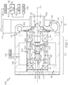
FIG. 1 is a schematic view of a fuel cell system with a permanent magnet electric motor according to example embodiments of the present disclosure; -
FIG. 2 is a perspective view of a rotor assembly of the permanent magnet electric motor ofFIG. 1 , wherein the rotor assembly is shown in an assembled state; -
FIG. 3 is an exploded perspective view of the rotor assembly ofFIG. 2 ; -
FIG. 4 is a section view of the rotor assembly taken along the line 4-4 ofFIG. 2 ; -
FIG. 5 is a perspective view of shaft structures of the rotor assembly ofFIG. 2 ; -
FIG. 6 is a section view of the rotor assembly taken along the line 6-6 ofFIG. 2 . - The following detailed description is merely exemplary in nature and is not intended to limit the present disclosure or the application and uses of the present disclosure. Furthermore, there is no intention to be bound by any theory presented in the preceding background or the following detailed description.
- Broadly, example embodiments disclosed herein include a well-built, high efficiency permanent magnet electric motor with a rotor assembly that has improved manufacturability. The rotor assembly may include a magnet member that is retained together with a jacket member using a shaft arrangement that includes a plurality of shaft structures. In some embodiments, the shaft structures load the magnet member toward the jacket member in a radially outward direction. As such, in some embodiments, components of the magnet member are compressed (outward and inward) in the radial direction between the shaft arrangement and the jacket member.
- In some embodiments, the shaft arrangement may include a first shaft structure (i.e,. a first stub shaft, a first half-shaft structure, etc.) and a second shaft structure (i.e,. a second stub shaft, a second half-shaft structure, etc.). The first and second shaft structures may be fixedly attached and interlocked within the magnet member. The first and second shaft structures may be attached, for example, at respective ends within the magnet member. The shaft structures may also be interference and/or frictionally fit within the magnet member to provide the radially directed load to the magnet member. More specifically, the diameter of the shaft arrangement may be slightly greater than a diameter of a bore defined by the magnet member to provide the interference/frictional fit therebetween. Additionally, the shaft arrangement may compress, align, and/or retain the magnet member in the axial direction. For example, the shaft structures may be fixedly attached to the jacket member, thereby retaining the magnet member within the jacket member. In some embodiments, the shaft structures and the jacket member may encapsulate the magnet member within the axial ends and within the inner diameter of the jacket member.
- The shaft structures may be fixedly attached together at a coupling, which may be of a variety of types without departing from the scope of the present disclosure. For example, in some embodiments, the coupling may be a male-female coupling in which the second shaft structure receives a portion of the first shaft structure. More specifically, in some embodiments, the first shaft structure may include at least one projection, and the second shaft structure may include at least one recess that receives the projection of the first shaft structure.
- Also, the magnet member may include two or more segments. At least one of the shaft structures may load the segments of the magnet member outward radially to retain the magnet segments and the jacket member together. The magnet member may include additional components for interconnecting and retaining the components of the rotor assembly. For example, the rotor assembly may include one or more inter-magnet members and axial end members that engage each other and/or engage the magnet segments to securely retain the components.
- Accordingly, as will be discussed, the rotor assembly of the present disclosure provides a number of benefits. The shaft arrangement and magnet member are configured such that the rotor assembly may be manufactured efficiently, accurately, and in a repeatable fashion. Also, the rotor assembly ensures that the permanent magnet electric motor has high efficiency operation, durability, and other advantages.
- Referring now to
FIG. 1 , afuel cell system 100 with anexample charging device 102 is shown. The chargingdevice 102 includes anelectric motor 103 with arotor assembly 148 that is configured according to example embodiments of the present disclosure. It will be appreciated that theelectric motor 103 and therotor assembly 148 therein may be included in a different system (other than a fuel cell system) without departing from the scope of the present disclosure. - The
fuel cell system 100 may include afuel cell stack 104 containing a plurality of fuel cells. Hydrogen may be supplied to thefuel cell stack 104 from atank 106, and oxygen may be supplied to thefuel cell stack 104 to generate electricity by a known chemical reaction. Thefuel cell stack 104 may generate electricity for anelectric motor 105 as well as other connected electrical devices. Thefuel cell system 100 may be included in a vehicle, such as a car, truck, sport utility vehicle, van, motorcycle, etc. Accordingly, in some embodiments, theelectric motor 105 may convert the electrical power generated by thefuel cell stack 104 to mechanical power to drive and rotate an axle (and, thus, one or more wheels) of the vehicle. However, it will be appreciated that thefuel cell system 100 may be configured for a different use without departing from the scope of the present disclosure. - Oxygen may be provided to the
fuel cell stack 104, at least in part, by the chargingdevice 102. The chargingdevice 102 may be configured as an electric compressor device (i.e., electric supercharger) with a single-stage compressor in some embodiments. - As shown in
FIG. 1 , the chargingdevice 102 may generally include arotating group 118 and ahousing 119. Therotating group 118 may be supported for rotation within thehousing 119 about an axis ofrotation 120 by one ormore bearings 121. The bearing(s) 121 may have various configurations, such as a plain bearing, an air bearing, an oil-less bearing, a rolling element bearing, etc. - The charging
device 102 may define amotor section 112. Themotor section 112 may include theelectric motor 103 mentioned above. In addition to therotor assembly 148, themotor 103 may also include astator 146, which receives therotor assembly 148. Thestator 146 may include a plurality of windings that conduct electricity. Furthermore, themotor section 112 may include part of thehousing 119. Specifically, themotor section 112 may include amotor housing 123, which supports thestator 146 and houses both thestator 146 and therotor assembly 148. Therotor assembly 148 may include amagnet member 220, which will be discussed in detail below. Thefuel cell stack 104 may provide electricity for thestator 146 to drivingly rotate themagnet member 220 of therotor assembly 148 and other components of therotating group 118. - The charging
device 102 may also include acompressor section 110. In some embodiments, thecompressor section 110 may be the sole (only) compressor section of thecharging device 102. In other embodiments, there may be a plurality of compressor sections to define amulti-stage charging device 102. Thecompressor section 110 may include acompressor wheel 130, which is fixed to therotor assembly 148 to be part of therotating group 118. Although partially shown inFIG. 1 , thecompressor wheel 130 may include ahub portion 145 that is fixed to therotor assembly 148 of themotor section 112 via one or more fasteners, weldments, and/or other attachment. Thecompressor section 110 may also define part of thehousing 119. Specifically, thecompressor section 110 may include acompressor housing member 136, which is fixed to an axial end of themotor housing 123, and which defines anaxial inlet 138, ashroud member 139, and avolute member 140. Theaxial inlet 138,shroud member 139, andvolute member 140 may be attached together in a unitary, one-piececompressor housing member 136. Theaxial inlet 138 may be tubular, straight, and centered on theaxis 120. Theshroud member 139 may be inversely shaped according to components of thecompressor wheel 130. Thevolute member 140 may define avolute passage 142 therein that extends about theaxis 120. Thevolute member 140 may also define anoutlet 143. - Accordingly, the
motor 103 may drivingly rotate thecompressor wheel 130 about theaxis 120. An inlet airstream (represented by arrows 122) may flow into theinlet 138, flow through theshroud member 139, and flow into thevolute passage 142. A resultant compressed airstream (represented by arrow 124) may be directed to anintercooler 128 and then to thefuel cell stack 104 for boosting the operating efficiency of thefuel cell system 100. - Furthermore, an exhaust gas stream (represented by arrow 132) from the
fuel cell stack 104 may be exhausted to atmosphere as represented inFIG. 1 . Stated differently, theexhaust gas stream 132 may be directed away from the chargingdevice 102. In other embodiments, theexhaust gas stream 132 may be directed back toward thecharging device 102, for example, to drive rotation of a turbine wheel that is included in therotating group 118. This may, in turn, drive rotation of thecompressor wheel 130, for example, to assist theelectric motor 103. - Various components of the
fuel cell system 100 may be controlled by acontrol system 134. Thecontrol system 134 may be a computerized system with a processor, various sensors, and other components for electrically controlling operation of themotor 103, thefuel cell stack 104, and/or other features of thesystem 100. In some embodiments, thecontrol system 134 may receive sensor input (e.g., indicating speed of themotor 105, etc.) and control the speed of themotor 103 according to that input. Thecontrol system 134 may define or may be part of the electrical control unit (ECU) of a vehicle. - Referring now to
FIGS. 2 and3 , therotor assembly 148 of themotor 103 will be discussed in greater detail according to example embodiments of the present disclosure. Thestator 146 is shown schematically and in phantom to reveal therotor assembly 148. - As shown, the
rotor assembly 148 may include ajacket member 210. Thejacket member 210 may be a unitary, hollow tube. In some embodiments, thejacket member 210 may be centered about theaxis 120. Thejacket member 210 may include afirst end 212 and asecond end 214 that are spaced apart along theaxis 120. As shown inFIGS. 3 and4 , thejacket member 210 may also include an inner surface 216 (inner diameter surface) that faces and encircles theaxis 120. As shown inFIGS. 2-4 , thejacket member 210 may also include an outer surface 218 (outer diameter surface) that faces outward radially from theaxis 120. The inner and/orouter surfaces inner surface 216 and theouter surface 218 may be substantially constant along the length of thejacket member 210. Furthermore, theinner surface 216 may define acentral bore 217 extending axially through thejacket member 210. - The
rotor assembly 148 may further include themagnet member 220. Themagnet member 220 may be substantially cylindrical and hollow so as to define a central aperture 226 (FIGS. 1 and6 ). Thecentral aperture 226 may be centered on and may extend through themagnet member 220 along theaxis 120 from an openfirst end 222 to an open second end 224 (FIG. 1 ). - The
magnet member 220 may include a plurality of segments that are constructed from and/or that include a permanent magnet. In some embodiments, for example, themagnet member 220 includes a firstarcuate magnet segment 228 and a secondarcuate magnet segment 238. The first andsecond magnet segments axis 120 at different angular positions. The firstarcuate magnet segment 228 may be referred to as a north pole magnet, and the secondarcuate magnet segment 238 may be referred to as a south pole magnet. Although only two magnet segments are shown, it will be appreciated that themagnet member 220 may include more than two segments arranged about theaxis 120 without departing from the scope of the present disclosure. - As shown in
FIG. 3 , the firstarcuate magnet segment 228 may be arcuate (e.g., with a semi-circular cross section) and may extend in a circumferential direction about theaxis 120 between a firstcircumferential edge 230 and an opposite secondcircumferential edge 232. The firstarcuate magnet segment 228 may also extend along theaxis 120. The firstarcuate magnet segment 228 may further include aninner face 234 that faces and arcuately contours about theaxis 120. Moreover, anouter face 236 may face radially outward from theaxis 120 and may arcuately contour about theaxis 120. - The second
arcuate magnet segment 238 may be substantially similar to the firstarcuate magnet segment 228. Accordingly, the secondarcuate magnet segment 238 may be arcuate (e.g., semi-circular) and may extend in a circumferential direction about theaxis 120 between a firstcircumferential edge 240 and a secondcircumferential edge 242. The secondarcuate magnet segment 238 may further include aninner face 244 that faces and arcuately contours about theaxis 120. Moreover, anouter face 246 may face radially outward from theaxis 120 and may arcuately contour about theaxis 120. - Furthermore, the
magnet member 220 may include a firstinter-magnet plate 248 and a secondinter-magnet plate 250. The first and/or secondinter-magnet plates plates inter-magnet plate 248 may be disposed in a circumferential direction between the firstcircumferential edge 230 of the firstarcuate magnet segment 228 and the secondcircumferential edge 242 of the secondarcuate magnet segment 238. Similarly, the secondinter-magnet plate 250 may be disposed in a circumferential direction between the firstcircumferential edge 240 of the secondarcuate magnet segment 238 and the secondcircumferential edge 232 of the firstarcuate magnet segment 228. - The
magnet member 220 may further include a firstaxial end plate 252. The firstaxial end plate 252 may be an annular disc made from a strong and rigid material. The firstaxial end plate 252 may include acentral opening 251 that is centered on theaxis 120. The firstaxial end plate 252 may also include anannular recess 253 on an outer axial face thereof. Theannular recess 253 may include aninner diameter surface 255 that faces theaxis 120. Theinner diameter surface 255 may define at least part of thecentral opening 251 in some embodiments. - Moreover, the
magnet member 220 may include a secondaxial end plate 266. The secondaxial end plate 266 may be substantially similar to the firstaxial end plate 252. Accordingly, the secondaxial end plate 266 may be an annular disc made from a strong and rigid material. The secondaxial end plate 266 may include acentral opening 261 that is centered on theaxis 120. Although not shown, the secondaxial end plate 266 may also include an annular recess (similar to the recess 253) on an outer axial face thereof. - Additionally, as shown in
FIGS. 3 and4 , the inner axial face of the secondaxial end plate 266 may include aslot 274. Theslot 274 may be straight and may extend radially (FIG. 3 ). The longitudinal axis of theslot 274 may intersect theaxis 120, and thecentral opening 261 may bisect theslot 274 in some embodiments. Theslot 274 may be open at the outer diameter edge of the secondaxial end plate 266 and/or at thecentral opening 261. As shown inFIGS. 3 and4 , the firstaxial end plate 252 may similarly include aslot 254 on the inner axial face thereof. - Thus, in some embodiments, the
magnet member 220 may be collectively defined by the first and secondarcuate magnet segments inter-magnet plates axial end plates arcuate magnet segments inter-magnet plates end plates axis 120 and may collectively define its cylindrical shape and profile. These parts may collectively define thecentral aperture 226 of themagnet member 220. Thecentral opening 251 of the firstaxial end plate 252 may define the openfirst end 222 of thecentral aperture 226 of themagnet member 220. Thecentral opening 261 of the secondaxial end plate 266 may define the opensecond end 224 of themagnet member 220. Also, the inner faces 234, 244 of themagnet segments inter-magnet plates central aperture 226. - As shown in
FIG. 4 , the firstaxial end plate 252 may be engaged with the firstinter-magnet plate 248. For example, as shown, the axial edge of the firstinter-magnet plate 248 may be received within theslot 254 of the firstaxial end plate 252. The opposite axial edge of the firstinter-magnet plate 248 may be similarly received in theslot 274 of the secondaxial end plate 266 to engage therewith. Likewise, the secondinter-magnet plate 250 may be received within theslots axial end plates axial end plates inter-magnet plates axis 120. Also, as shown inFIG. 4 , the inner axial face of the first and secondaxial end plates arcuate magnet segments magnet segments end plates inter-magnet plates axis 120. Also, theinter-magnet plates magnet segments axis 120. - The
magnet member 220 may be received within thejacket member 210. As will be discussed, in some embodiments, theouter face 236 of the firstarcuate magnet segment 228 may abut against theinner surface 216 of thejacket member 210. Likewise, theouter face 246 of the secondarcuate magnet segment 238 may abut against theinner surface 216. Also, in some embodiments, the outer edges of the first and secondinter-magnet plates inner surface 216. Furthermore, the outer diameter surfaces of the first and secondaxial end plates inner surface 216. - The
rotor assembly 148 may further include ashaft arrangement 280. Theshaft arrangement 280 may have a variety of configurations without departing from the scope of the present disclosure. In general, at least part of theshaft arrangement 280 may be received in thecentral aperture 226 of themagnet member 220 and may be engaged with themagnet member 220. Theshaft arrangement 280 may also be fixedly attached to thejacket member 210. - Also, the
shaft arrangement 280 may provide an outwardly directed load to themagnet member 220 and may cooperate with thejacket member 210 to compress the components of themagnet member 220 in the radial direction with respect to theaxis 120. Thus, theshaft arrangement 280 may retain themagnet member 220 and thejacket member 210 together. Furthermore, theshaft arrangement 280 may support other features of therotating group 118 as well. For example, thecompressor wheel 130 may be fixed on and supported by theshaft arrangement 280 for rotation about theaxis 120. Also, in some embodiments, theshaft arrangement 280 may be supported by the bearing(s) 121 for rotation about theaxis 120 relative to thestator 146 and thehousing 119. - The
shaft arrangement 280 is shown in isolation inFIG. 5 with themagnet member 220 and thejacket member 210 shown schematically in phantom. In some embodiments, theshaft arrangement 280 may include afirst shaft structure 282 and asecond shaft structure 296. Thefirst shaft structure 282 may be referred to as a first stub shaft in that thefirst shaft structure 282 extends partly along theaxis 120 of therotor assembly 148, and thesecond shaft structure 296 may be referred to as a second stub shaft in that thesecond shaft structure 296 extends partly along theaxis 120 of therotor assembly 148. Thefirst shaft structure 282 may be disposed proximate one axial end of therotor assembly 148, and thesecond shaft structure 296 may be disposed proximate the opposite axial end. Thefirst shaft structure 282 may be substantially similar to thesecond shaft structure 296 except as noted herein. Also, ends (stub ends) of the first andsecond shaft structures internal coupling 211. At least one of (e.g., each of) the first andsecond shaft structures magnet member 220, pushing the components of themagnet member 220 outward radially against theinner surface 216 of thejacket member 210 for retaining the same in a fixed position within therotor assembly 148. - As shown in
FIGS. 3 and5 , thefirst shaft structure 282 may be a unitary, one-piece member that is made from strong and substantially rigid metallic material. Thefirst shaft structure 282 may include abase 284 and astub 288 that projects axially from thebase 284. Also, abore 293 may extend through thefirst shaft structure 282. Thebore 293 may be centered on theaxis 120 and may pass through thebase 284 and thestub 288 from one axial end of thefirst shaft structure 282 to the other. Thus, thefirst shaft structure 282 may have an annular and hollow cross section taken perpendicular to theaxis 120. - As shown in
FIG. 1 , the diameter of thebore 293 at an outeraxial end 285 of theshaft structure 282 may be greater than the diameter of thebore 293 at a first inner axial end 286 (first stub end) thereof. The outeraxial end 285 of theshaft structure 282 may support thecompressor wheel 130, fasteners, and/or other components of therotating group 118 as schematically represented inFIG. 1 . - The outer diameter of the
first shaft structure 282 may vary along its axial length. For example, thebase 284 may generally have a larger diameter than thestub 288. The base 284 may include one or more circumferential grooves, disc-like projections, etc. on the outer diameter surface thereof. The base 284 may vary in diameter along its axial length with an intermediate, disc-shapedflange 283 having the greatest diameter of thefirst shaft structure 282. Thestub 288 may project axially away from one side of theflange 283, and the outeraxial end 285 may project axially away from the other side of theflange 283. - Likewise, the
second shaft structure 296 may be a unitary, one-piece member that is made from strong and rigid metallic material. Thesecond shaft structure 296 may include abase 297 and astub 298 that projects axially from thebase 297. Also, a bore 271 (FIGS. 3 and6 ) may extend through thesecond shaft structure 296. Thebore 271 may comprise an opening that is centered on theaxis 120 and that passes continuously through thebase 297 and thestub 298 from one axial end of thesecond shaft structure 296 to the other. Thus, thesecond shaft structure 296 may have an annular and hollow cross section taken perpendicular to theaxis 120. - The base 297 may generally have a larger diameter than the
stub 298. The base 297 may vary in diameter along its axial length with an intermediate, disc-shapedflange 275 having the greatest diameter of thesecond shaft structure 296. Thestub 298 may project axially away from one side of theflange 275 and a grooved outeraxial end 257 may project axially away from the other side of theflange 275. Thestub 298 may terminate at a second inner axial end 278 (second stub end) of thesecond shaft structure 296. Also, thestub 298 may include ashoulder 281 proximate theflange 275, and theshoulder 281 may define an outer diameter surface that faces outward radially. Although hidden inFIG. 3 , thestub 288 of thefirst shaft structure 282 may include ashoulder 281 as well. - The first inner
axial end 286 and the second inneraxial end 278 may be configured to attach together at the internal coupling 211 (FIGS. 5 and6 ). The first and second inner axial ends 286,278 may cooperatively define theinternal coupling 211. For example, in some embodiments, the coupling may be a male-female coupling, wherein one of theends coupling 211 may comprise a so-called "gib key" attachment, wherein theends ends shaft structures - More specifically, in some embodiments represented in
FIG. 6 , the first inneraxial end 286 of theshaft structure 282 may include ataper 304 at which the outer diameter of thestub 288 gradually reduces as thestub 288 extends axially toward its terminal end. Also, the first inneraxial end 286 may include aradial projection 300. Theradial projection 300 may project radially outward from theaxis 120. In some embodiments, theradial projection 300 may extend annularly and continuously about theaxis 120. Also, as shown inFIG. 6 , theradial projection 300 may have an axial cross-sectional profile having tapered surfaces on both sides of a plateaued surface. Stated differently, the radius of theradial projection 300 varies such that, moving along theaxis 120 away from thetaper 304, the radius at theradial projection 300 increases gradually, then remains constant, and then gradually reduces. This profile may remain consistent about theaxis 120 such that the tapered and plateaued surfaces of theradial projection 300 extend annularly, continuously, and uninterrupted about theaxis 120 in the circumferential direction. Additionally, the inneraxial end 286 may include anaxial projection 302. Theaxial projection 302 may be a relatively thin-walled cylinder with a substantially constant radius on its inner and outer diameter surfaces and that projects axially to define the terminus of the inneraxial end 286. Also, thebore 293 may be stepped proximate theaxial projection 302 to define an inner shoulder 305 as shown inFIG. 6 . - Furthermore, the second inner
axial end 278 may include ataper 309 at which the outer diameter of thestub 298 reduces slightly. The second inneraxial end 278 may also include aradial aperture 306. Theradial aperture 306 may correspond in shape, dimension, etc. to that of theradial projection 300. Thus, theradial aperture 306 may be a notch that is recessed radially outward with respect to theaxis 120, and the profile of theradial aperture 306 may include tapered surfaces on both sides of a plateaued surface such that theradial aperture 306 is substantially inverse to theradial projection 300. Also, theradial aperture 306 may extend continuously and annularly about theaxis 120. Furthermore, the inneraxial end 278 may include anaxial recess 308. Theaxial recess 308 may correspond in shape, dimension, etc. to that of theaxial projection 302. Accordingly, theaxial recess 308 may be a cylindrical recess disposed between the inner and outer diameter surfaces of the second inneraxial end 278. - As shown in
FIG. 6 , the first inneraxial end 286 may be attached to the second inneraxial end 278 at theinternal coupling 211 of theshaft arrangement 280. Specifically, theradial aperture 306 may receive theradial projection 300. Also, theaxial recess 308 may receive theaxial projection 302 with the second inneraxial end 278 abutting the shoulder 305 of the first inneraxial end 286. The opposing surfaces of the first and second inner axial ends 286, 278 may abut and frictionally engage each other such that the first andsecond shaft structures - Additionally, as shown in
FIGS. 1 and6 , thefirst shaft structure 282 and thesecond shaft structure 296 may be fixedly attached to themagnet member 220. Thestub 288 of thefirst shaft structure 282 may be received within thefirst end 222 of thecentral aperture 226 of themagnet member 220, thestub 298 of thesecond shaft structure 296 may be received within thesecond end 224 of thecentral aperture 226 of themagnet member 220, and the firstaxial end 286 may be fixedly attached to the secondaxial end 278 at theinternal coupling 211 as described above. The outer diameter surface of at least one (e.g., both) of thestubs magnet member 220. More specifically, in some embodiments represented inFIG. 6 , thestubs magnet segments outer diameter dimension 310 may be slightly greater than theinner diameter dimension 312; therefore, theshaft arrangement 280 may be interference fit to themagnet member 220 within thejacket member 210. (It will be appreciated that thejacket member 210 defines a fixedinner diameter dimension 313, which is configured such that thejacket member 210 counters the radial load from theshaft arrangement 280. Accordingly, themagnet segments shaft arrangement 280 and thejacket member 210.) The radial compressive load on themagnet member 220 may be distributed substantially evenly about theaxis 120. Also, theshaft arrangement 280 may load the firstarcuate magnet segment 228 generally in one radial direction away from theaxis 120, and theshaft arrangement 280 may load the secondarcuate magnet segment 238 generally in an opposite radial direction away from theaxis 120. Thus,shaft arrangement 280 may cooperate with thejacket member 210 to compress and retain themagnet member 220. - Additionally, the
first shaft structure 282 may be received in thecentral opening 251 of the firstaxial end plate 252. Thesecond shaft structure 296 may be similarly received in thecentral opening 261 of the secondaxial end plate 266. In this position, the outer diameter surface of theshoulder 281 of theshaft structures inner diameter surface 255 of the first and secondaxial end plates first shaft structure 282 may be engaged with the firstaxial end plate 252, and the base 284 may project axially outward from thefirst end 222 of themagnet member 220. Likewise, thesecond shaft structure 296 may be engaged with the secondaxial end plate 266, and the base 257 may project axially outward from thesecond end 224 of themagnet member 220. - To manufacture the
rotor assembly 148, the parts described above may be constructed or otherwise provided using casting techniques, additive manufacturing, or other manufacturing methods. Then, the firstarcuate magnet segment 228, the firstinter-magnet plate 248, the secondarcuate magnet segment 238, and the secondinter-magnet plate 250 may be assembled together in the cylindrical configuration described above. Next, in some embodiments, thejacket member 210 may be placed over and may receive the assembled firstarcuate magnet segment 228, the firstinter-magnet plate 248, the secondarcuate magnet segment 238, and the secondinter-magnet plate 250. - In some embodiments, there may be sufficient radial clearance (e.g., between the
inner surface 216 and the outer faces 236, 246) at or about room temperature (i.e., normal ambient temperature) to allow thejacket member 210 to slide over themagnet segments 228, 238 (i.e., without having to heat the jacket member 210). Accordingly, manufacture may be completed in an efficient manner. - Subsequently, the
axial end plates magnet member 220. In some embodiments, theend plates inter-magnet plates 248 250 received in theslots shaft structures end plates stubs central openings - Subsequently, an axial load may be applied (e.g., using a press) to compress the components of the
rotor assembly 148 together toward the axial center. As the load is increased, thestubs central openings shaft members rotor assembly 148. Eventually, theradial projection 300 may abut against the inneraxial end 278 of thesecond shaft structure 296. Axial compression force may be increased so that second inneraxial end 278 resiliently flexes outward radially and/or the first inneraxial end 286 resiliently flexes inward radially, allowing theradial projection 300 to move into theradial aperture 306. The second inneraxial end 278 and/or the first inneraxial end 286 may resiliently recover back toward its neutral position once theradial projection 300 comes to rest within theradial aperture 306. As shown inFIG. 6 , theaxial projection 302 may also be received in theaxial recess 308 once theshaft structures - Assembly may also cause the
shaft structures end plates shaft structures end plates magnet segments inter-magnet plates slots shaft structures - Once fully compressed, the
shaft structures jacket member 210. In some embodiments, theflange 283 of thefirst shaft structure 282 may be welded to one end of thejacket member 210, and theflange 275 of thesecond shaft structure 296 may be welded to the opposite end of thejacket member 210. For example, spot welding, laser welding, or other types of welding processes may be used to produce one or more weldments that fixedly attach thejacket member 210 to theshaft structures axis 120 or may be formed as a partial or continuous arcuate weldment about theaxis 120. Thus, therotor assembly 148 may be strong and robust, retaining components together in the axial direction. - Moreover, as discussed, the
shaft arrangement 280 and thejacket member 210 may radially compress themagnet segments magnet member 220 to limit (prevent) relative radial or axial movement between these components. Also, theinter-magnet plates end plates magnet segments rotor assembly 148 may be strong and robust. - Furthermore, as explained above, assembly of the
rotor assembly 148 may be completed efficiently, repeatably, and accurately. The parts may be individually formed within tolerances that are very manageable. Theshaft structures - Once assembled, the
rotor assembly 148 may be attached to thecompressor wheel 130 and/or installed within thestator 146 of themotor 103. Then, themotor 103 may be installed within thefuel cell system 100. - While at least one exemplary embodiment has been presented in the foregoing detailed description, it should be appreciated that a vast number of variations exist. It should also be appreciated that the exemplary embodiment or exemplary embodiments are only examples, and are not intended to limit the scope, applicability, or configuration of the present disclosure in any way. Rather, the foregoing detailed description will provide those skilled in the art with a convenient road map for implementing an exemplary embodiment of the present disclosure. It is understood that various changes may be made in the function and arrangement of elements described in an exemplary embodiment without departing from the scope of the present disclosure as set forth in the appended claims.
Claims (15)
- A rotor assembly for a permanent magnet electric motor that defines an axis of rotation comprising:a jacket member;a magnet member that is received within the jacket member, the magnet member defining a central aperture with a first end and a second end, the axis of rotation extending through the first end and the second end;a shaft arrangement with a first shaft structure and a second shaft structure, the first shaft structure received in the first end of the magnet member, the second shaft structure received in the second end of the magnet member, the first shaft structure and the second shaft structure being attached within the magnet member at an internal coupling, the shaft arrangement and the jacket member cooperating to compress the magnet member radially with respect to the axis of rotation.
- The rotor assembly of claim 1, wherein the magnet member includes a first arcuate magnet segment and a second arcuate magnet segment, the first and second arcuate magnetic segments collectively extending about the axis of rotation;
wherein the shaft arrangement and the jacket member cooperate to compress the first arcuate magnet segment and the second arcuate magnet segment radially with respect to the axis of rotation. - The rotor assembly of claim 2, wherein at least one of the first shaft structure and the second shaft structure abuts includes an outer surface that abuts a first inner face of the first arcuate magnet segment and a second inner face of the second arcuate magnet segment;
wherein the outer surface defines an outer width dimension;
wherein an inner width dimension is defined between the first inner face and the second inner face; and
wherein the outer width dimension is greater than the inner width dimension, and / or wherein the rotor assembly further comprises
an inter-magnet plate that is disposed in a circumferential direction between the first arcuate magnet segment and the second arcuate magnet segment;
further comprising an axial end plate that is disposed proximate an axial end of the magnet member; and
wherein the inter-magnet plate is engaged with the axial end plate. - The rotor assembly of any preceding claim, wherein the first shaft structure includes a first stub end and the second shaft structure includes a second stub end; and
wherein the first stub end is received in the second stub end and attached at the internal coupling. - The rotor assembly of claim 4, wherein the first stub end includes a projection that projects radially outward from the axis of rotation; and
wherein the second stub end includes an aperture that is recessed radially outward and that receives the projection at the internal coupling to attach the first shaft structure and the second shaft structure. - The rotor assembly of claim 5, wherein the projection has a tapered surface that tapers in radius with respect to the axis of rotation.
- The rotor assembly of claim 6, wherein the tapered surface extends about the axis of rotation in a circumferential direction, wherein, optionally, the tapered surface extends annularly and continuously about the axis of rotation; and
wherein the aperture is a notch that extends annularly and continuously about the axis of rotation and that corresponds to the projection. - The rotor assembly of claim 5, wherein the projection is a first radial projection and the aperture is a first radial recess;
wherein the first stub end includes a second projection that projects axially with respect to the axis of rotation; and
wherein the second stub end includes a second aperture that is recessed axially and that receives the second projection. - The rotor assembly of any preceding claim, wherein the first shaft structure is unitary and the second shaft is unitary; and
wherein the internal coupling is cooperatively defined by the first shaft structure and the second shaft structure, and / or wherein at least one of the first and second shaft structures includes a base and a stub that projects axially from the base;
wherein the stub is received within the central aperture of the magnet member; and wherein the base projects outward from the magnet member. - A method of manufacturing a rotor assembly for a permanent magnet electric motor having an axis of rotation comprising:providing a first shaft structure and a second shaft structure of a shaft arrangement;providing a magnet member that is received within a jacket member, the magnet member including a central aperture with a first end and a second end;moving the first shaft structure into the first end, moving the second shaft structure into the second end, and attaching the first shaft structure and the second shaft structure at an internal coupling within the magnet member to compress the magnet member radially with respect to the axis of rotation between the shaft arrangement and the jacket member.
- The method of claim 10, wherein providing the magnet member includes providing a first arcuate magnet segment and a second arcuate magnet segment;
and further comprising compressing the first arcuate magnet segment and the second arcuate magnet segment radially between the jacket member and at least one of the first and second shaft structures. - The method of claim 11, further comprising disposing an inter-magnet plate in a circumferential direction between the first arcuate magnet segment and the second arcuate magnet segment; and
further comprising disposing an axial end plate proximate an axial end of the first and second arcuate magnet segments and engaging the inter-magnet plate with the axial end plate, wherein, optionally,
the inter-magnet plate is a first inter-magnet plate and the axial end plate is a first axial end plate;
further comprising disposing a second inter-magnet plate in the circumferential direction between the first and second arcuate magnet segments and spaced apart in the circumferential direction from the first inter-magnet plate; and
further comprising disposing the first and second axial end plates on opposite axial ends of the first and second arcuate magnet segments, engaging the first axial end plate with the first and second inter-magnet plates, and engaging the second axial end plate with the first and second inter-magnet plates;
further comprising moving the first shaft structure into the first end of the magnet member to engage the first axial end plate, and fixing the first shaft structure to the jacket member; and
further comprising moving the second shaft structure into the second end of the magnet member to engage the second axial end plate, and fixing the second shaft structure to the jacket member. - The method of claim 11, wherein attaching the first shaft structure and the second shaft structure includes moving at least one projection of a first stub end of the first shaft structure into at least one aperture of a second stub end of the second shaft structure.
- The method of claim 13, wherein the at least one projection is a radial projection that projects radially outward and wherein the at least one aperture is a radial recess that is recessed radially outward; and
wherein attaching the first shaft structure and the second shaft structure includes moving the radial projection into the radial recess, wherein, optionally,
the at least one projection includes the radial projection and an axial projection that projects axially from the first stub end;
wherein the at least one recess includes the radial recess and an axial recess that is recessed axially into the second stub end; and
wherein attaching the first shaft structure and the second shaft structure includes moving the axial projection into the axial recess. - A permanent magnet electric motor comprising:a stator; anda rotor assembly supported for rotation within the stator about an axis of rotation, the rotor assembly comprising:a jacket member that is hollow and cylindrical;a cylindrical magnet member that includes a first arcuate magnet segment, a second arcuate magnet segment, a first inter-magnet plate, a second inter-magnet plate, a first axial end plate, and a second axial end plate, the first and second inter-magnet plates being disposed between the first and second arcuate magnet segments, the first and second inter-magnet plates being spaced apart in a circumferential direction with respect to the axis, the first and second axial end plates disposed on opposite axial ends of the magnet member, the magnet member defining a central aperture with the first axial end plate defining an open first axial end of the magnet member and the second axial end plate defining an open second axial end of the magnet member; anda shaft arrangement with a first shaft structure and a second shaft structure, the first shaft structure including a radial projection, the second shaft structure having a radial recess, the first shaft structure partly received in the open first end of the magnet member, the second shaft structure partly received in the open second end of the magnet member, the radial projection of the first shaft structure received in the radial recess of the second shaft structure to attach the first shaft structure to the second shaft structure within the central aperture, the first and second shaft structures and the jacket member cooperating to compress the magnet member radially with respect to the axis of rotation.
Applications Claiming Priority (1)
| Application Number | Priority Date | Filing Date | Title |
|---|---|---|---|
| US16/536,012 US11283313B2 (en) | 2019-08-08 | 2019-08-08 | Rotor assembly for permanent magnet electric motor with plurality of shaft structures |
Publications (1)
| Publication Number | Publication Date |
|---|---|
| EP3799263A1 true EP3799263A1 (en) | 2021-03-31 |
Family
ID=71078471
Family Applications (1)
| Application Number | Title | Priority Date | Filing Date |
|---|---|---|---|
| EP20178899.9A Pending EP3799263A1 (en) | 2019-08-08 | 2020-06-09 | Rotor assembly for permanent magnet electric motor with plurality of shaft structures |
Country Status (3)
| Country | Link |
|---|---|
| US (1) | US11283313B2 (en) |
| EP (1) | EP3799263A1 (en) |
| CN (1) | CN112350470A (en) |
Families Citing this family (1)
| Publication number | Priority date | Publication date | Assignee | Title |
|---|---|---|---|---|
| US11979062B2 (en) | 2021-12-22 | 2024-05-07 | Garrett Transportation I Inc | Rotor assembly for turbomachine having electric motor with solitary solid core permanent magnet |
Citations (5)
| Publication number | Priority date | Publication date | Assignee | Title |
|---|---|---|---|---|
| JP2000060041A (en) * | 1998-08-05 | 2000-02-25 | Takano Co Ltd | Manufacturing method of magnet rotor |
| DE20307198U1 (en) * | 2003-05-08 | 2003-09-25 | Minebea Co.,Ltd., Kitasaku, Nagano | Rotor for an electric motor |
| CN105305680A (en) * | 2014-06-16 | 2016-02-03 | 发那科株式会社 | Rotor member, rotor, rotating electrical machine, and method of disassembling a rotor |
| US20160049845A1 (en) * | 2014-08-12 | 2016-02-18 | Zilift Holdings, Limited | Magnetic rotor shaft module and a rotor assembly incorporating the same |
| US20180069451A1 (en) * | 2016-09-08 | 2018-03-08 | Borgwarner Inc. | Electric motor rotor with extended shoulders for bearings |
Family Cites Families (6)
| Publication number | Priority date | Publication date | Assignee | Title |
|---|---|---|---|---|
| US4876492A (en) * | 1988-02-26 | 1989-10-24 | General Electric Company | Electronically commutated motor driven apparatus including an impeller in a housing driven by a stator on the housing |
| JP2010154699A (en) * | 2008-12-26 | 2010-07-08 | Hitachi Ltd | Magnetic flux variable type rotating electrical machine |
| CN205647075U (en) * | 2016-01-22 | 2016-10-12 | 珠海格力节能环保制冷技术研究中心有限公司 | Electric motor rotor and permanent -magnet machine |
| CN106130223B (en) * | 2016-08-04 | 2018-12-07 | 珠海格力电器股份有限公司 | Rotating shaft, assembling method of rotating shaft and motor |
| CN106130222B (en) * | 2016-08-04 | 2018-12-07 | 珠海格力电器股份有限公司 | Rotating shaft, assembling method of rotating shaft and motor |
| CN109768687A (en) * | 2019-01-23 | 2019-05-17 | 北京智拓博科技有限公司 | A kind of permanent magnet machine rotor and its manufacturing method and motor and air blower |
-
2019
- 2019-08-08 US US16/536,012 patent/US11283313B2/en active Active
-
2020
- 2020-06-09 EP EP20178899.9A patent/EP3799263A1/en active Pending
- 2020-08-07 CN CN202010789053.1A patent/CN112350470A/en active Pending
Patent Citations (5)
| Publication number | Priority date | Publication date | Assignee | Title |
|---|---|---|---|---|
| JP2000060041A (en) * | 1998-08-05 | 2000-02-25 | Takano Co Ltd | Manufacturing method of magnet rotor |
| DE20307198U1 (en) * | 2003-05-08 | 2003-09-25 | Minebea Co.,Ltd., Kitasaku, Nagano | Rotor for an electric motor |
| CN105305680A (en) * | 2014-06-16 | 2016-02-03 | 发那科株式会社 | Rotor member, rotor, rotating electrical machine, and method of disassembling a rotor |
| US20160049845A1 (en) * | 2014-08-12 | 2016-02-18 | Zilift Holdings, Limited | Magnetic rotor shaft module and a rotor assembly incorporating the same |
| US20180069451A1 (en) * | 2016-09-08 | 2018-03-08 | Borgwarner Inc. | Electric motor rotor with extended shoulders for bearings |
Also Published As
| Publication number | Publication date |
|---|---|
| CN112350470A (en) | 2021-02-09 |
| US11283313B2 (en) | 2022-03-22 |
| US20210044164A1 (en) | 2021-02-11 |
Similar Documents
| Publication | Publication Date | Title |
|---|---|---|
| CN103620182B (en) | The balance adjusting structure and its method of supercharging device built in motor | |
| EP3279446B1 (en) | Motor rotor structure for electric turbo charger and method of assembling same | |
| JP2012255355A5 (en) | ||
| WO2008130139A2 (en) | Motor having rotors arranged concentrically and driving apparatus having the motor | |
| CN113756878B (en) | Compressor device with turbine section water recirculation path | |
| US10355544B2 (en) | Rotor member fixed to rotary shaft of electrical rotating machine, rotor, rotary electric machine and method for disassembling rotor | |
| EP3934063A1 (en) | Rotor assembly for electric motor of turbomachine with carbon-carbon composite magnet-retaining jacket member | |
| US11283313B2 (en) | Rotor assembly for permanent magnet electric motor with plurality of shaft structures | |
| EP4203252A1 (en) | Rotor assembly for turbomachine having electric motor with solitary solid core permanent magnet | |
| CA2298742A1 (en) | Integral throttle body and torque motor | |
| US11131313B2 (en) | Single-stage compressor with bleed system for thrust load alleviation | |
| EP3772801B1 (en) | Rotor assembly for permanent magnet electric motor with radially biasing shaft structure | |
| US10451085B2 (en) | Assembly methods for the connection of a turbine wheel to a shaft | |
| EP4012161B1 (en) | E-assist turbocharger with bleed fluid system connecting compressor section to web ring of turbine section for thrust load suppression | |
| CN115653707B (en) | Turbomachinery with roller element bearing arrangements | |
| KR101289800B1 (en) | Permanent magnetic motor and fluid charger comprising the same | |
| CN222582141U (en) | A balance weight rotor assembly made of magnetic conductive material | |
| US11689076B2 (en) | Motor cooling system for e-boosting device | |
| US20180106263A1 (en) | Single piece bearing housing with turbine end plate | |
| JP2539220B2 (en) | Engine start charging device |
Legal Events
| Date | Code | Title | Description |
|---|---|---|---|
| PUAI | Public reference made under article 153(3) epc to a published international application that has entered the european phase |
Free format text: ORIGINAL CODE: 0009012 |
|
| STAA | Information on the status of an ep patent application or granted ep patent |
Free format text: STATUS: REQUEST FOR EXAMINATION WAS MADE |
|
| 17P | Request for examination filed |
Effective date: 20200609 |
|
| AK | Designated contracting states |
Kind code of ref document: A1 Designated state(s): AL AT BE BG CH CY CZ DE DK EE ES FI FR GB GR HR HU IE IS IT LI LT LU LV MC MK MT NL NO PL PT RO RS SE SI SK SM TR |
|
| AX | Request for extension of the european patent |
Extension state: BA ME |
|
| P01 | Opt-out of the competence of the unified patent court (upc) registered |
Effective date: 20230424 |
|
| STAA | Information on the status of an ep patent application or granted ep patent |
Free format text: STATUS: EXAMINATION IS IN PROGRESS |
|
| 17Q | First examination report despatched |
Effective date: 20230914 |