EP3799225A1 - Harness assembly - Google Patents
Harness assembly Download PDFInfo
- Publication number
- EP3799225A1 EP3799225A1 EP20199464.7A EP20199464A EP3799225A1 EP 3799225 A1 EP3799225 A1 EP 3799225A1 EP 20199464 A EP20199464 A EP 20199464A EP 3799225 A1 EP3799225 A1 EP 3799225A1
- Authority
- EP
- European Patent Office
- Prior art keywords
- overbraid
- cable
- harness assembly
- around
- braid
- Prior art date
- Legal status (The legal status is an assumption and is not a legal conclusion. Google has not performed a legal analysis and makes no representation as to the accuracy of the status listed.)
- Granted
Links
Images



Classifications
-
- H—ELECTRICITY
- H01—ELECTRIC ELEMENTS
- H01R—ELECTRICALLY-CONDUCTIVE CONNECTIONS; STRUCTURAL ASSOCIATIONS OF A PLURALITY OF MUTUALLY-INSULATED ELECTRICAL CONNECTING ELEMENTS; COUPLING DEVICES; CURRENT COLLECTORS
- H01R13/00—Details of coupling devices of the kinds covered by groups H01R12/70 or H01R24/00 - H01R33/00
- H01R13/648—Protective earth or shield arrangements on coupling devices, e.g. anti-static shielding
- H01R13/658—High frequency shielding arrangements, e.g. against EMI [Electro-Magnetic Interference] or EMP [Electro-Magnetic Pulse]
- H01R13/6591—Specific features or arrangements of connection of shield to conductive members
- H01R13/6592—Specific features or arrangements of connection of shield to conductive members the conductive member being a shielded cable
- H01R13/6593—Specific features or arrangements of connection of shield to conductive members the conductive member being a shielded cable the shield being composed of different pieces
-
- B—PERFORMING OPERATIONS; TRANSPORTING
- B60—VEHICLES IN GENERAL
- B60R—VEHICLES, VEHICLE FITTINGS, OR VEHICLE PARTS, NOT OTHERWISE PROVIDED FOR
- B60R16/00—Electric or fluid circuits specially adapted for vehicles and not otherwise provided for; Arrangement of elements of electric or fluid circuits specially adapted for vehicles and not otherwise provided for
- B60R16/02—Electric or fluid circuits specially adapted for vehicles and not otherwise provided for; Arrangement of elements of electric or fluid circuits specially adapted for vehicles and not otherwise provided for electric constitutive elements
- B60R16/0207—Wire harnesses
- B60R16/0215—Protecting, fastening and routing means therefor
-
- H—ELECTRICITY
- H01—ELECTRIC ELEMENTS
- H01R—ELECTRICALLY-CONDUCTIVE CONNECTIONS; STRUCTURAL ASSOCIATIONS OF A PLURALITY OF MUTUALLY-INSULATED ELECTRICAL CONNECTING ELEMENTS; COUPLING DEVICES; CURRENT COLLECTORS
- H01R13/00—Details of coupling devices of the kinds covered by groups H01R12/70 or H01R24/00 - H01R33/00
- H01R13/58—Means for relieving strain on wire connection, e.g. cord grip, for avoiding loosening of connections between wires and terminals within a coupling device terminating a cable
- H01R13/5841—Means for relieving strain on wire connection, e.g. cord grip, for avoiding loosening of connections between wires and terminals within a coupling device terminating a cable allowing different orientations of the cable with respect to the coupling direction
-
- H—ELECTRICITY
- H01—ELECTRIC ELEMENTS
- H01R—ELECTRICALLY-CONDUCTIVE CONNECTIONS; STRUCTURAL ASSOCIATIONS OF A PLURALITY OF MUTUALLY-INSULATED ELECTRICAL CONNECTING ELEMENTS; COUPLING DEVICES; CURRENT COLLECTORS
- H01R13/00—Details of coupling devices of the kinds covered by groups H01R12/70 or H01R24/00 - H01R33/00
- H01R13/648—Protective earth or shield arrangements on coupling devices, e.g. anti-static shielding
- H01R13/658—High frequency shielding arrangements, e.g. against EMI [Electro-Magnetic Interference] or EMP [Electro-Magnetic Pulse]
- H01R13/6591—Specific features or arrangements of connection of shield to conductive members
- H01R13/65912—Specific features or arrangements of connection of shield to conductive members for shielded multiconductor cable
- H01R13/65914—Connection of shield to additional grounding conductors
-
- H—ELECTRICITY
- H01—ELECTRIC ELEMENTS
- H01R—ELECTRICALLY-CONDUCTIVE CONNECTIONS; STRUCTURAL ASSOCIATIONS OF A PLURALITY OF MUTUALLY-INSULATED ELECTRICAL CONNECTING ELEMENTS; COUPLING DEVICES; CURRENT COLLECTORS
- H01R13/00—Details of coupling devices of the kinds covered by groups H01R12/70 or H01R24/00 - H01R33/00
- H01R13/648—Protective earth or shield arrangements on coupling devices, e.g. anti-static shielding
- H01R13/658—High frequency shielding arrangements, e.g. against EMI [Electro-Magnetic Interference] or EMP [Electro-Magnetic Pulse]
- H01R13/6591—Specific features or arrangements of connection of shield to conductive members
- H01R13/65912—Specific features or arrangements of connection of shield to conductive members for shielded multiconductor cable
- H01R13/65917—Connection to shield by means of resilient members
-
- H—ELECTRICITY
- H01—ELECTRIC ELEMENTS
- H01R—ELECTRICALLY-CONDUCTIVE CONNECTIONS; STRUCTURAL ASSOCIATIONS OF A PLURALITY OF MUTUALLY-INSULATED ELECTRICAL CONNECTING ELEMENTS; COUPLING DEVICES; CURRENT COLLECTORS
- H01R2201/00—Connectors or connections adapted for particular applications
- H01R2201/26—Connectors or connections adapted for particular applications for vehicles
Definitions
- the present disclosure generally relates to a harness assembly, such as for connecting sensors with another component, including harness assemblies that may be used in connection with engines, such as in connection with vehicles.
- Cables and lead wires can act as unintended antennas to both receive and to radiate an electromagnetic interference (EMI) signal.
- shields are often incorporated in cable designs as additional conductors added to the cables or wires to help isolate the electromagnetic fields of conductors within the shield from those outside of the shield.
- Such cable designs may be used, for example, in harness assemblies for connecting sensors, such as a quantitative debris monitoring (QDM) sensor of a vehicle engine's oil debris monitoring system (ODMS), to another component, such as a signal conditioner unit (SCU) in the vehicle.
- QDM quantitative debris monitoring
- ODMS oil debris monitoring system
- SCU signal conditioner unit
- a harness assembly may include a cable having a cable shielding around at least a portion of a plurality of wires, a connector with an integrated backshell arranged at an angle with respect to the cable, an external braid disposed around at least a portion of the backshell and the cable, and an overbraid around at least a portion of the external braid, the overbraid having two layers.
- a method for assembling a harness assembly may include arranging a cable and a connector with an integrated backshell at an angle with respect to one another, providing an external braid around at least a portion of the backshell and an end of the cable adjacent to the connector, and providing an overbraid around at least a portion of the external braid, the overbraid having two layers.
- a harness assembly 10 may include a cable 12 and a connector 14 arranged adjacent a first end of the cable 12.
- the connector 14 may be arranged at an angle with respect to the cable 12, which may be varied based upon a particular required cable configuration. Without limitation, in embodiments, the angle may be approximately 90 degrees. In other embodiments, the angle may be approximately 45 degrees.
- the cable 12 may include a cable shielding 16 through which wires 20 extend, and the cable shielding may terminate at or within the connector 14.
- An opposing end of the cable 12 may be configured for attachment and/or connection to a sensor, such as, for example and without limitation, a quantitative debris monitoring (QDM) sensor of a vehicle engine's oil debris monitoring system (ODMS).
- QDM quantitative debris monitoring
- ODMS oil debris monitoring system
- the connector 14 may generally be configured for attachment and/or connection to another component, such as a signal conditioning unit (SCU) of the vehicle.
- a Teflon tubing 18 may be provided at or around a first end of the cable 12.
- the connector 14 may be, for example, an EN2997 connector, and may include an integrated backshell 22, such as generally illustrated in FIG. 2 .
- the harness assembly 10 may include an external braid 24 disposed around at least a portion of the backshell 22 and around the first end of the cable 12, which may include the Teflon tubing 18.
- the harness assembly 10 may further include an overbraid 26 disposed around at least a portion of the external braid 24.
- the overbraid 26 may include a first layer 28 and a second layer 30.
- the overbraid 26 may be made from a single material that is folded over at least a portion of itself to form the layers 28, 30.
- the folded end 32 may be in a region of the backshell 22 and a free end 34 of the overbraid 26 may be in a region of the first end of the cable 12.
- the double layer configuration of the overbraid 26 may reduce the size of potential gaps in the braid, thereby enhancing the shielding effectiveness against electromagnetic interference. Such a configuration further may, inter alia, reduce weight and/or cost.
- the external braid 24 and/or the overbraid 26 may be comprised of copper and/or may be nickel-plated.
- the external braid 24 and the first layer 28 of the overbraid 26 may be connected or secured to the backshell 22, for example, via a band 36.
- the second layer 30 of the overbraid 26 may be disposed around the band 36.
- the overbraid 26 is comprised of a single material folded over itself, the single material may be folded over the band 36.
- the free end 34 of the overbraid 26 may be secured to the cable 12, for example, via a cable tie 38.
- the harness assembly 10 may include shrink tubing 40 around at least a portion of the overbraid 26 in a region of the backshell 22 and/or shrink tubing 42 around at least a portion of the overbraid 26 in a region of the first end of the cable 12 and/or around at least portion of the cable 12.
- the harness assembly 10 may further include a heat shrink boot 44 from the connector 14 to the cable 12.
- the heat shrink boot 44 generally may have an angled configuration at a same or similar angle at which the cable 12 and the connector 14 are arranged with respect to each other, e.g., 45 degrees or 90 degrees.
- the shrink tubing 40, 42 and/or the heat shrink boot 44 may be made of a fluoroelastomer material, and further may be bonded via a compatible epoxy.
- the shrink tubing 40, 42 and/or the heat shrink boot 44 generally may provide for environmental protection and/or sealing.
- a service loop in the wires 20 may be accessible by cutting back the shrink boot 44.
- a method for assembling a harness assembly 10 may include arranging a cable 12 and a connector 14 at an angle with respect to one another.
- the method may include providing an external braid 24 around at least a portion of a backshell 22 integrated with the connector 14 and around a first end of the cable 12 adjacent to the connector 14.
- the method may include feeding the wires 20 through a wall of the external braid 24 prior to termination.
- This may allow the external braid 24 to be installed as a flat braid on one side of the backshell 22 (e.g., the side facing the cable 12).
- the external braid 24 generally should not stretch significantly in a direction that is not axial to the braid 24 to avoid overstretching.
- the flat braid may hold more strength than a stretched braid around the circular backshell 22, thereby better ensuring that strain relief may be achieved and/or avoiding over-stretching of the braid.
- the method may include providing an overbraid 26 around at least a portion of the external braid 24, where the overbraid 26 may have two layers 28 and 30.
- the two layers 28 and 30 may be formed by providing a single material of the overbraid 26 having extra length, such as generally shown in FIG. 4 , and folding the single material over at least a portion of itself, such as generally shown in FIG. 5 .
- the method may also include securing the single material of the overbraid 26 to the external braid 24 in a region of the connector 14, for example, via a band 36, where the single material may be folded over the band 36.
- the method may further include securing a free end 34 of the overbraid 26 opposite a folded end 32 to the external braid 24 in a region of the first end of the cable 12.
- the method may further include providing a shrink tubing 40 around at least a portion of the overbraid 26 in a region of the backshell 22 and/or shrink tubing 42 around at least a portion of the overbraid 26 in a region of the first end of the cable 12 and/or around at least portion of the cable 12 and/or providing a heat shrink boot 44 from the connector 14 to the cable 12.
- the shrink tubing 40, 42 and/or the heat shrink boot 44 may be bonded via a compatible epoxy.
- references to a single element are not necessarily so limited and may include one or more of such element.
- Any directional references e.g., plus, minus, upper, lower, upward, downward, left, right, leftward, rightward, top, bottom, above, below, vertical, horizontal, clockwise, and counterclockwise
- Any directional references are only used for identification purposes to aid the reader's understanding of the present disclosure, and do not create limitations, particularly as to the position, orientation, or use of embodiments.
- joinder references are to be construed broadly and may include intermediate members between a connection of elements and relative movement between elements. As such, joinder references do not necessarily imply that two elements are directly connected/coupled and in fixed relation to each other.
- the use of "e.g.” in the specification is to be construed broadly and is used to provide non-limiting examples of embodiments of the disclosure, and the disclosure is not limited to such examples.
- Uses of "and” and “or” are to be construed broadly (e.g., to be treated as "and/or”). For example and without limitation, uses of "and” do not necessarily require all elements or features listed, and uses of "or” are intended to be inclusive unless such a construction would be illogical.
Landscapes
- Engineering & Computer Science (AREA)
- Mechanical Engineering (AREA)
- Details Of Indoor Wiring (AREA)
Abstract
Description
- This application claims the benefit of India Provisional Patent Application Serial No.
201911039581, filed on September 30, 2019 - The present disclosure generally relates to a harness assembly, such as for connecting sensors with another component, including harness assemblies that may be used in connection with engines, such as in connection with vehicles.
- This background description is set forth below for the purpose of providing context only. Therefore, any aspect of this background description, to the extent that it does not otherwise qualify as prior art, is neither expressly nor impliedly admitted as prior art against the instant disclosure.
- Cables and lead wires can act as unintended antennas to both receive and to radiate an electromagnetic interference (EMI) signal. As such, shields are often incorporated in cable designs as additional conductors added to the cables or wires to help isolate the electromagnetic fields of conductors within the shield from those outside of the shield. Such cable designs may be used, for example, in harness assemblies for connecting sensors, such as a quantitative debris monitoring (QDM) sensor of a vehicle engine's oil debris monitoring system (ODMS), to another component, such as a signal conditioner unit (SCU) in the vehicle. Considerations that go into the cable designs include, but are not limited to, pull strength, strain relief, EMI protection, repairability, environmental sealing, environmental compatibility, ease of manufacturing, and weight.
- There is a desire for solutions/options that minimize or eliminate one or more challenges or shortcomings of cable designs, particularly in to harness assemblies, with respect to one or more of these considerations. The foregoing discussion is intended only to illustrate examples of the present field and should not be taken as a disavowal of scope.
- In embodiments, a harness assembly may include a cable having a cable shielding around at least a portion of a plurality of wires, a connector with an integrated backshell arranged at an angle with respect to the cable, an external braid disposed around at least a portion of the backshell and the cable, and an overbraid around at least a portion of the external braid, the overbraid having two layers.
- In embodiments, a method for assembling a harness assembly may include arranging a cable and a connector with an integrated backshell at an angle with respect to one another, providing an external braid around at least a portion of the backshell and an end of the cable adjacent to the connector, and providing an overbraid around at least a portion of the external braid, the overbraid having two layers.
- The foregoing and other aspects, features, details, utilities, and/or advantages of embodiments of the present disclosure will be apparent from reading the following description, and from reviewing the accompanying drawings.
-
-
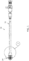
FIG. 1 is a top view generally illustrating an embodiment of a harness assembly according to teachings of the present disclosure. -
FIG. 2 is a cross-sectional view generally illustrating an embodiment of a connector of a harness assembly according to teachings of the present disclosure. -
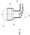
FIGS. 3-5 are cross-sectional views generally illustrating an embodiment of a method for assembling a harness assembly with a connector according to teachings of the present disclosure. - Reference will now be made in detail to embodiments of the present disclosure, examples of which are described herein and illustrated in the accompanying drawings. While the present disclosure will be described in conjunction with embodiments and/or examples, it will be understood that they are not intended to limit the present disclosure to these embodiments and/or examples. On the contrary, the present disclosure is intended to cover alternatives, modifications, and equivalents.
- In embodiments, such as generally illustrated in
FIGS. 1 and2 , aharness assembly 10 may include acable 12 and aconnector 14 arranged adjacent a first end of thecable 12. Theconnector 14 may be arranged at an angle with respect to thecable 12, which may be varied based upon a particular required cable configuration. Without limitation, in embodiments, the angle may be approximately 90 degrees. In other embodiments, the angle may be approximately 45 degrees. Thecable 12 may include acable shielding 16 through whichwires 20 extend, and the cable shielding may terminate at or within theconnector 14. An opposing end of thecable 12 may be configured for attachment and/or connection to a sensor, such as, for example and without limitation, a quantitative debris monitoring (QDM) sensor of a vehicle engine's oil debris monitoring system (ODMS). Theconnector 14 may generally be configured for attachment and/or connection to another component, such as a signal conditioning unit (SCU) of the vehicle. A Teflontubing 18 may be provided at or around a first end of thecable 12. - With embodiments, the
connector 14 may be, for example, an EN2997 connector, and may include an integratedbackshell 22, such as generally illustrated inFIG. 2 . Theharness assembly 10 may include anexternal braid 24 disposed around at least a portion of thebackshell 22 and around the first end of thecable 12, which may include the Teflontubing 18. - In embodiments, the
harness assembly 10 may further include an overbraid 26 disposed around at least a portion of theexternal braid 24. The overbraid 26 may include afirst layer 28 and asecond layer 30. In embodiments, the overbraid 26 may be made from a single material that is folded over at least a portion of itself to form thelayers end 32 may be in a region of thebackshell 22 and afree end 34 of the overbraid 26 may be in a region of the first end of thecable 12. However, it should be appreciated that the foldedend 32 and thefree end 34 may be switched. The double layer configuration of the overbraid 26 may reduce the size of potential gaps in the braid, thereby enhancing the shielding effectiveness against electromagnetic interference. Such a configuration further may, inter alia, reduce weight and/or cost. - With embodiments, the
external braid 24 and/or the overbraid 26 may be comprised of copper and/or may be nickel-plated. - In embodiments, the
external braid 24 and thefirst layer 28 of the overbraid 26 may be connected or secured to thebackshell 22, for example, via aband 36. Thesecond layer 30 of the overbraid 26 may be disposed around theband 36. Where the overbraid 26 is comprised of a single material folded over itself, the single material may be folded over theband 36. Thefree end 34 of the overbraid 26 may be secured to thecable 12, for example, via acable tie 38. - With embodiments, the
harness assembly 10 may includeshrink tubing 40 around at least a portion of the overbraid 26 in a region of thebackshell 22 and/orshrink tubing 42 around at least a portion of the overbraid 26 in a region of the first end of thecable 12 and/or around at least portion of thecable 12. Theharness assembly 10 may further include aheat shrink boot 44 from theconnector 14 to thecable 12. Theheat shrink boot 44 generally may have an angled configuration at a same or similar angle at which thecable 12 and theconnector 14 are arranged with respect to each other, e.g., 45 degrees or 90 degrees. Theshrink tubing heat shrink boot 44 may be made of a fluoroelastomer material, and further may be bonded via a compatible epoxy. Theshrink tubing heat shrink boot 44 generally may provide for environmental protection and/or sealing. A service loop in thewires 20 may be accessible by cutting back theshrink boot 44. - With embodiments generally illustrated in
FIGS. 3-5 , a method for assembling aharness assembly 10 may include arranging acable 12 and aconnector 14 at an angle with respect to one another. The method may include providing anexternal braid 24 around at least a portion of abackshell 22 integrated with theconnector 14 and around a first end of thecable 12 adjacent to theconnector 14. - In embodiments, the method may include feeding the
wires 20 through a wall of theexternal braid 24 prior to termination. This may allow theexternal braid 24 to be installed as a flat braid on one side of the backshell 22 (e.g., the side facing the cable 12). Commonly, to achieve a full or significant effect of the strain relief capabilities, theexternal braid 24 generally should not stretch significantly in a direction that is not axial to thebraid 24 to avoid overstretching. When stretched, the flat braid may hold more strength than a stretched braid around thecircular backshell 22, thereby better ensuring that strain relief may be achieved and/or avoiding over-stretching of the braid. - With embodiments, the method may include providing an overbraid 26 around at least a portion of the
external braid 24, where the overbraid 26 may have twolayers layers FIG. 4 , and folding the single material over at least a portion of itself, such as generally shown inFIG. 5 . - In embodiments, the method may also include securing the single material of the overbraid 26 to the
external braid 24 in a region of theconnector 14, for example, via aband 36, where the single material may be folded over theband 36. The method may further include securing afree end 34 of the overbraid 26 opposite a foldedend 32 to theexternal braid 24 in a region of the first end of thecable 12. - With embodiments, the method may further include providing a
shrink tubing 40 around at least a portion of the overbraid 26 in a region of thebackshell 22 and/orshrink tubing 42 around at least a portion of the overbraid 26 in a region of the first end of thecable 12 and/or around at least portion of thecable 12 and/or providing aheat shrink boot 44 from theconnector 14 to thecable 12. Theshrink tubing heat shrink boot 44 may be bonded via a compatible epoxy. - Various embodiments are described herein for various apparatuses, systems, and/or methods. Numerous specific details are set forth to provide a thorough understanding of the overall structure, function, manufacture, and use of the embodiments as described in the specification and illustrated in the accompanying drawings. It will be understood by those skilled in the art, however, that the embodiments may be practiced without such specific details. In other instances, well-known operations, components, and elements have not been described in detail so as not to obscure the embodiments described in the specification. Those of ordinary skill in the art will understand that the embodiments described and illustrated herein are non-limiting examples, and thus it can be appreciated that the specific structural and functional details disclosed herein may be representative and do not necessarily limit the scope of the embodiments.
- Reference throughout the specification to "various embodiments," "with embodiments," "in embodiments," or "an embodiment," or the like, means that a particular feature, structure, or characteristic described in connection with the embodiment is included in at least one embodiment. Thus, appearances of the phrases "in various embodiments," "with embodiments," "in embodiments," or "an embodiment," or the like, in places throughout the specification are not necessarily all referring to the same embodiment. Furthermore, the particular features, structures, or characteristics may be combined in any suitable manner in one or more embodiments. Thus, the particular features, structures, or characteristics illustrated or described in connection with one embodiment/example may be combined, in whole or in part, with the features, structures, functions, and/or characteristics of one or more other embodiments/examples without limitation given that such combination is not illogical or non-functional. Moreover, many modifications may be made to adapt a particular situation or material to the teachings of the present disclosure without departing from the scope thereof.
- It should be understood that references to a single element are not necessarily so limited and may include one or more of such element. Any directional references (e.g., plus, minus, upper, lower, upward, downward, left, right, leftward, rightward, top, bottom, above, below, vertical, horizontal, clockwise, and counterclockwise) are only used for identification purposes to aid the reader's understanding of the present disclosure, and do not create limitations, particularly as to the position, orientation, or use of embodiments.
- Joinder references (e.g., attached, coupled, connected, and the like) are to be construed broadly and may include intermediate members between a connection of elements and relative movement between elements. As such, joinder references do not necessarily imply that two elements are directly connected/coupled and in fixed relation to each other. The use of "e.g." in the specification is to be construed broadly and is used to provide non-limiting examples of embodiments of the disclosure, and the disclosure is not limited to such examples. Uses of "and" and "or" are to be construed broadly (e.g., to be treated as "and/or"). For example and without limitation, uses of "and" do not necessarily require all elements or features listed, and uses of "or" are intended to be inclusive unless such a construction would be illogical.
- While processes, systems, and methods may be described herein in connection with one or more steps in a particular sequence, it should be understood that such methods may be practiced with the steps in a different order, with certain steps performed simultaneously, with additional steps, and/or with certain described steps omitted.
- It is intended that all matter contained in the above description or shown in the accompanying drawings shall be interpreted as illustrative only and not limiting. Changes in detail or structure may be made without departing from the present disclosure.
Claims (16)
- A harness assembly, comprising:a cable having a cable shielding around at least a portion of a plurality of wires;a connector with an integrated backshell arranged at an angle with respect to the cable;an external braid disposed around at least a portion of the backshell and the cable; andan overbraid around at least a portion of the external braid, the overbraid having two layers.
- The harness assembly of claim 1, wherein the angle is substantially is approximately 90 degrees, and preferably approximately 45 degrees.
- The harness assembly of claim 1, further comprising a band disposed around a first of the two layers of the overbraid, a second of the two layers of the overbraid being disposed around the band.
- The harness assembly of claim 1, wherein the overbraid is a single material folded over at least a portion of itself to form the two layers.
- The harness assembly of claim 1, wherein the overbraid is nickel-plated.
- The harness assembly of claim 1, further comprising shrink tubing over at least a portion of the overbraid in a region of the backshell.
- The harness assembly of claim 1, further comprising a cable tie around at least a portion of the overbraid in a region of an end of the cable.
- The harness assembly of claim 1, wherein at least a portion of the external braid is configured as a flat braid.
- The harness assembly of claim 1, further comprising a Teflon tubing disposed at an end of the cable between the cable shielding and the external braid.
- A method for assembling a harness assembly, comprising:arranging a cable and a connector with an integrated backshell at an angle with respect to one another;providing an external braid around at least a portion of the backshell and an end of the cable adjacent to the connector;providing an overbraid around at least a portion of the external braid, the overbraid having two layers.
- The method of claim 10, further comprising feeding the cable through a wall of the external braid prior to termination.
- The method of claim 10, wherein providing the overbraid includes applying a single material of the overbraid over the at least a portion of the external braid, and folding the single material over at least a portion of itself to form the two layers.
- The method of claim 12, further comprising securing the single material of the overbraid to the at least a portion of the external braid in a region of the connector via a band, wherein the single material is folded over the band.
- The method of claim 12, further comprising securing an end of the overbraid opposite a folded end of the overbraid to the at least a portion of the external braid in a region of the end of the cable adjacent to the connector.
- The method of claim 10, wherein the angle is approximately 90 degrees, and preferably approximately 45 degrees.
- The method of claim 10, wherein the angle is approximately 45 degrees.
Applications Claiming Priority (2)
| Application Number | Priority Date | Filing Date | Title |
|---|---|---|---|
| IN201911039581 | 2019-09-30 | ||
| US17/034,705 US11646129B2 (en) | 2019-09-30 | 2020-09-28 | Harness assembly |
Publications (2)
| Publication Number | Publication Date |
|---|---|
| EP3799225A1 true EP3799225A1 (en) | 2021-03-31 |
| EP3799225B1 EP3799225B1 (en) | 2024-11-20 |
Family
ID=72717667
Family Applications (1)
| Application Number | Title | Priority Date | Filing Date |
|---|---|---|---|
| EP20199464.7A Active EP3799225B1 (en) | 2019-09-30 | 2020-09-30 | Harness assembly |
Country Status (1)
| Country | Link |
|---|---|
| EP (1) | EP3799225B1 (en) |
Citations (3)
| Publication number | Priority date | Publication date | Assignee | Title |
|---|---|---|---|---|
| US4026628A (en) * | 1975-04-21 | 1977-05-31 | Grumman Aerospace Corporation | Electrical connector for cables and magnetic forming process for same |
| US6143986A (en) * | 1996-04-19 | 2000-11-07 | Rohr, Inc. | Method and arrangement for easily repairing electrical harness for aircraft jet engine |
| EP2892109A1 (en) * | 2014-01-03 | 2015-07-08 | Rohr, Inc. | Systems and methods for electrical harness construction |
-
2020
- 2020-09-30 EP EP20199464.7A patent/EP3799225B1/en active Active
Patent Citations (3)
| Publication number | Priority date | Publication date | Assignee | Title |
|---|---|---|---|---|
| US4026628A (en) * | 1975-04-21 | 1977-05-31 | Grumman Aerospace Corporation | Electrical connector for cables and magnetic forming process for same |
| US6143986A (en) * | 1996-04-19 | 2000-11-07 | Rohr, Inc. | Method and arrangement for easily repairing electrical harness for aircraft jet engine |
| EP2892109A1 (en) * | 2014-01-03 | 2015-07-08 | Rohr, Inc. | Systems and methods for electrical harness construction |
Also Published As
| Publication number | Publication date |
|---|---|
| EP3799225B1 (en) | 2024-11-20 |
Similar Documents
| Publication | Publication Date | Title |
|---|---|---|
| CN104067468B (en) | Electromagnetic shield and wire harness | |
| EP2298608B1 (en) | Device comprising a vehicle and a wire harness | |
| US9343821B2 (en) | Terminal waterproofing structure of wire harness | |
| JP6225836B2 (en) | Connector structure | |
| US9748704B2 (en) | Shield connector structure | |
| US9263865B2 (en) | Water stop structure for wire harness and wire harness | |
| EP3467963A1 (en) | Method of assembling a high-voltage splice device comprising an electromagnetic interference splice shield | |
| US8926246B2 (en) | Bolt support structure | |
| JP2007311356A (en) | Shield sealed electrical harness | |
| CN102781729A (en) | Wire harness routing structure | |
| JP2015119576A (en) | Protective wire | |
| JP2013162728A (en) | Electromagnetic shield tool and wire harness | |
| US7530847B2 (en) | Impact-resistant, high-strength, braided wiring harness | |
| JP2018107961A (en) | Protective tube and harness | |
| US11646129B2 (en) | Harness assembly | |
| EP3799225B1 (en) | Harness assembly | |
| JP2015130276A (en) | Shielded wire | |
| JP5367882B1 (en) | Connector and connector connection structure | |
| JP2012075253A (en) | Waterproof device and waterproof method for electric wire, control device, and construction machinery | |
| CN105936247B (en) | Wire protective component | |
| CN222262280U (en) | Coil assembly and electronic expansion valve with same | |
| EP2600471A1 (en) | Terminal cable assembly having water proof structure | |
| CN108819877A (en) | Harness is protected after a kind of automobile | |
| KR20240019314A (en) | electrical connector unit | |
| JP2022124868A (en) | wire harness |
Legal Events
| Date | Code | Title | Description |
|---|---|---|---|
| PUAI | Public reference made under article 153(3) epc to a published international application that has entered the european phase |
Free format text: ORIGINAL CODE: 0009012 |
|
| STAA | Information on the status of an ep patent application or granted ep patent |
Free format text: STATUS: REQUEST FOR EXAMINATION WAS MADE |
|
| 17P | Request for examination filed |
Effective date: 20200930 |
|
| AK | Designated contracting states |
Kind code of ref document: A1 Designated state(s): AL AT BE BG CH CY CZ DE DK EE ES FI FR GB GR HR HU IE IS IT LI LT LU LV MC MK MT NL NO PL PT RO RS SE SI SK SM TR |
|
| AX | Request for extension of the european patent |
Extension state: BA ME |
|
| STAA | Information on the status of an ep patent application or granted ep patent |
Free format text: STATUS: EXAMINATION IS IN PROGRESS |
|
| 17Q | First examination report despatched |
Effective date: 20221201 |
|
| P01 | Opt-out of the competence of the unified patent court (upc) registered |
Effective date: 20230521 |
|
| GRAP | Despatch of communication of intention to grant a patent |
Free format text: ORIGINAL CODE: EPIDOSNIGR1 |
|
| STAA | Information on the status of an ep patent application or granted ep patent |
Free format text: STATUS: GRANT OF PATENT IS INTENDED |
|
| INTG | Intention to grant announced |
Effective date: 20240701 |
|
| GRAS | Grant fee paid |
Free format text: ORIGINAL CODE: EPIDOSNIGR3 |
|
| GRAA | (expected) grant |
Free format text: ORIGINAL CODE: 0009210 |
|
| STAA | Information on the status of an ep patent application or granted ep patent |
Free format text: STATUS: THE PATENT HAS BEEN GRANTED |
|
| AK | Designated contracting states |
Kind code of ref document: B1 Designated state(s): AL AT BE BG CH CY CZ DE DK EE ES FI FR GB GR HR HU IE IS IT LI LT LU LV MC MK MT NL NO PL PT RO RS SE SI SK SM TR |
|
| REG | Reference to a national code |
Ref country code: GB Ref legal event code: FG4D |
|
| REG | Reference to a national code |
Ref country code: CH Ref legal event code: EP |
|
| REG | Reference to a national code |
Ref country code: DE Ref legal event code: R096 Ref document number: 602020041574 Country of ref document: DE |
|
| REG | Reference to a national code |
Ref country code: IE Ref legal event code: FG4D |
|
| REG | Reference to a national code |
Ref country code: LT Ref legal event code: MG9D |
|
| REG | Reference to a national code |
Ref country code: NL Ref legal event code: MP Effective date: 20241120 |
|
| PG25 | Lapsed in a contracting state [announced via postgrant information from national office to epo] |
Ref country code: PT Free format text: LAPSE BECAUSE OF FAILURE TO SUBMIT A TRANSLATION OF THE DESCRIPTION OR TO PAY THE FEE WITHIN THE PRESCRIBED TIME-LIMIT Effective date: 20250320 Ref country code: IS Free format text: LAPSE BECAUSE OF FAILURE TO SUBMIT A TRANSLATION OF THE DESCRIPTION OR TO PAY THE FEE WITHIN THE PRESCRIBED TIME-LIMIT Effective date: 20250320 Ref country code: HR Free format text: LAPSE BECAUSE OF FAILURE TO SUBMIT A TRANSLATION OF THE DESCRIPTION OR TO PAY THE FEE WITHIN THE PRESCRIBED TIME-LIMIT Effective date: 20241120 |
|
| PG25 | Lapsed in a contracting state [announced via postgrant information from national office to epo] |
Ref country code: FI Free format text: LAPSE BECAUSE OF FAILURE TO SUBMIT A TRANSLATION OF THE DESCRIPTION OR TO PAY THE FEE WITHIN THE PRESCRIBED TIME-LIMIT Effective date: 20241120 Ref country code: NL Free format text: LAPSE BECAUSE OF FAILURE TO SUBMIT A TRANSLATION OF THE DESCRIPTION OR TO PAY THE FEE WITHIN THE PRESCRIBED TIME-LIMIT Effective date: 20241120 |
|
| REG | Reference to a national code |
Ref country code: AT Ref legal event code: MK05 Ref document number: 1744451 Country of ref document: AT Kind code of ref document: T Effective date: 20241120 |
|
| PG25 | Lapsed in a contracting state [announced via postgrant information from national office to epo] |
Ref country code: BG Free format text: LAPSE BECAUSE OF FAILURE TO SUBMIT A TRANSLATION OF THE DESCRIPTION OR TO PAY THE FEE WITHIN THE PRESCRIBED TIME-LIMIT Effective date: 20241120 |
|
| PG25 | Lapsed in a contracting state [announced via postgrant information from national office to epo] |
Ref country code: ES Free format text: LAPSE BECAUSE OF FAILURE TO SUBMIT A TRANSLATION OF THE DESCRIPTION OR TO PAY THE FEE WITHIN THE PRESCRIBED TIME-LIMIT Effective date: 20241120 |
|
| PG25 | Lapsed in a contracting state [announced via postgrant information from national office to epo] |
Ref country code: NO Free format text: LAPSE BECAUSE OF FAILURE TO SUBMIT A TRANSLATION OF THE DESCRIPTION OR TO PAY THE FEE WITHIN THE PRESCRIBED TIME-LIMIT Effective date: 20250220 |
|
| PG25 | Lapsed in a contracting state [announced via postgrant information from national office to epo] |
Ref country code: AT Free format text: LAPSE BECAUSE OF FAILURE TO SUBMIT A TRANSLATION OF THE DESCRIPTION OR TO PAY THE FEE WITHIN THE PRESCRIBED TIME-LIMIT Effective date: 20241120 Ref country code: LV Free format text: LAPSE BECAUSE OF FAILURE TO SUBMIT A TRANSLATION OF THE DESCRIPTION OR TO PAY THE FEE WITHIN THE PRESCRIBED TIME-LIMIT Effective date: 20241120 Ref country code: GR Free format text: LAPSE BECAUSE OF FAILURE TO SUBMIT A TRANSLATION OF THE DESCRIPTION OR TO PAY THE FEE WITHIN THE PRESCRIBED TIME-LIMIT Effective date: 20250221 |
|
| PG25 | Lapsed in a contracting state [announced via postgrant information from national office to epo] |
Ref country code: PL Free format text: LAPSE BECAUSE OF FAILURE TO SUBMIT A TRANSLATION OF THE DESCRIPTION OR TO PAY THE FEE WITHIN THE PRESCRIBED TIME-LIMIT Effective date: 20241120 |
|
| PG25 | Lapsed in a contracting state [announced via postgrant information from national office to epo] |
Ref country code: RS Free format text: LAPSE BECAUSE OF FAILURE TO SUBMIT A TRANSLATION OF THE DESCRIPTION OR TO PAY THE FEE WITHIN THE PRESCRIBED TIME-LIMIT Effective date: 20250220 |
|
| PG25 | Lapsed in a contracting state [announced via postgrant information from national office to epo] |
Ref country code: SM Free format text: LAPSE BECAUSE OF FAILURE TO SUBMIT A TRANSLATION OF THE DESCRIPTION OR TO PAY THE FEE WITHIN THE PRESCRIBED TIME-LIMIT Effective date: 20241120 |
|
| PG25 | Lapsed in a contracting state [announced via postgrant information from national office to epo] |
Ref country code: DK Free format text: LAPSE BECAUSE OF FAILURE TO SUBMIT A TRANSLATION OF THE DESCRIPTION OR TO PAY THE FEE WITHIN THE PRESCRIBED TIME-LIMIT Effective date: 20241120 |
|
| PG25 | Lapsed in a contracting state [announced via postgrant information from national office to epo] |
Ref country code: EE Free format text: LAPSE BECAUSE OF FAILURE TO SUBMIT A TRANSLATION OF THE DESCRIPTION OR TO PAY THE FEE WITHIN THE PRESCRIBED TIME-LIMIT Effective date: 20241120 |
|
| PG25 | Lapsed in a contracting state [announced via postgrant information from national office to epo] |
Ref country code: RO Free format text: LAPSE BECAUSE OF FAILURE TO SUBMIT A TRANSLATION OF THE DESCRIPTION OR TO PAY THE FEE WITHIN THE PRESCRIBED TIME-LIMIT Effective date: 20241120 |
|
| PG25 | Lapsed in a contracting state [announced via postgrant information from national office to epo] |
Ref country code: SK Free format text: LAPSE BECAUSE OF FAILURE TO SUBMIT A TRANSLATION OF THE DESCRIPTION OR TO PAY THE FEE WITHIN THE PRESCRIBED TIME-LIMIT Effective date: 20241120 |
|
| PG25 | Lapsed in a contracting state [announced via postgrant information from national office to epo] |
Ref country code: CZ Free format text: LAPSE BECAUSE OF FAILURE TO SUBMIT A TRANSLATION OF THE DESCRIPTION OR TO PAY THE FEE WITHIN THE PRESCRIBED TIME-LIMIT Effective date: 20241120 |
|
| REG | Reference to a national code |
Ref country code: DE Ref legal event code: R097 Ref document number: 602020041574 Country of ref document: DE |
|
| PG25 | Lapsed in a contracting state [announced via postgrant information from national office to epo] |
Ref country code: SE Free format text: LAPSE BECAUSE OF FAILURE TO SUBMIT A TRANSLATION OF THE DESCRIPTION OR TO PAY THE FEE WITHIN THE PRESCRIBED TIME-LIMIT Effective date: 20241120 |
|
| PLBE | No opposition filed within time limit |
Free format text: ORIGINAL CODE: 0009261 |
|
| STAA | Information on the status of an ep patent application or granted ep patent |
Free format text: STATUS: NO OPPOSITION FILED WITHIN TIME LIMIT |
|
| PGFP | Annual fee paid to national office [announced via postgrant information from national office to epo] |
Ref country code: DE Payment date: 20250820 Year of fee payment: 6 |
|
| PGFP | Annual fee paid to national office [announced via postgrant information from national office to epo] |
Ref country code: IT Payment date: 20250820 Year of fee payment: 6 |
|
| PGFP | Annual fee paid to national office [announced via postgrant information from national office to epo] |
Ref country code: GB Payment date: 20250822 Year of fee payment: 6 |
|
| PGFP | Annual fee paid to national office [announced via postgrant information from national office to epo] |
Ref country code: FR Payment date: 20250820 Year of fee payment: 6 |
|
| 26N | No opposition filed |
Effective date: 20250821 |
|
| REG | Reference to a national code |
Ref country code: CH Ref legal event code: H13 Free format text: ST27 STATUS EVENT CODE: U-0-0-H10-H13 (AS PROVIDED BY THE NATIONAL OFFICE) Effective date: 20260504 |