EP3799214A1 - Terminal, and mounting structure of terminal and mounting surface - Google Patents
Terminal, and mounting structure of terminal and mounting surface Download PDFInfo
- Publication number
- EP3799214A1 EP3799214A1 EP20198936.5A EP20198936A EP3799214A1 EP 3799214 A1 EP3799214 A1 EP 3799214A1 EP 20198936 A EP20198936 A EP 20198936A EP 3799214 A1 EP3799214 A1 EP 3799214A1
- Authority
- EP
- European Patent Office
- Prior art keywords
- terminal
- mounting surface
- contact portion
- stud bolt
- contact
- Prior art date
- Legal status (The legal status is an assumption and is not a legal conclusion. Google has not performed a legal analysis and makes no representation as to the accuracy of the status listed.)
- Granted
Links
Images



Classifications
-
- H—ELECTRICITY
- H01—ELECTRIC ELEMENTS
- H01R—ELECTRICALLY-CONDUCTIVE CONNECTIONS; STRUCTURAL ASSOCIATIONS OF A PLURALITY OF MUTUALLY-INSULATED ELECTRICAL CONNECTING ELEMENTS; COUPLING DEVICES; CURRENT COLLECTORS
- H01R11/00—Individual connecting elements providing two or more spaced connecting locations for conductive members which are, or may be, thereby interconnected, e.g. end pieces for wires or cables supported by the wire or cable and having means for facilitating electrical connection to some other wire, terminal, or conductive member, blocks of binding posts
- H01R11/11—End pieces or tapping pieces for wires, supported by the wire and for facilitating electrical connection to some other wire, terminal or conductive member
- H01R11/12—End pieces terminating in an eye, hook, or fork
-
- H—ELECTRICITY
- H01—ELECTRIC ELEMENTS
- H01R—ELECTRICALLY-CONDUCTIVE CONNECTIONS; STRUCTURAL ASSOCIATIONS OF A PLURALITY OF MUTUALLY-INSULATED ELECTRICAL CONNECTING ELEMENTS; COUPLING DEVICES; CURRENT COLLECTORS
- H01R11/00—Individual connecting elements providing two or more spaced connecting locations for conductive members which are, or may be, thereby interconnected, e.g. end pieces for wires or cables supported by the wire or cable and having means for facilitating electrical connection to some other wire, terminal, or conductive member, blocks of binding posts
- H01R11/11—End pieces or tapping pieces for wires, supported by the wire and for facilitating electrical connection to some other wire, terminal or conductive member
- H01R11/22—End pieces terminating in a spring clip
-
- H—ELECTRICITY
- H01—ELECTRIC ELEMENTS
- H01R—ELECTRICALLY-CONDUCTIVE CONNECTIONS; STRUCTURAL ASSOCIATIONS OF A PLURALITY OF MUTUALLY-INSULATED ELECTRICAL CONNECTING ELEMENTS; COUPLING DEVICES; CURRENT COLLECTORS
- H01R11/00—Individual connecting elements providing two or more spaced connecting locations for conductive members which are, or may be, thereby interconnected, e.g. end pieces for wires or cables supported by the wire or cable and having means for facilitating electrical connection to some other wire, terminal, or conductive member, blocks of binding posts
- H01R11/11—End pieces or tapping pieces for wires, supported by the wire and for facilitating electrical connection to some other wire, terminal or conductive member
- H01R11/26—End pieces terminating in a screw clamp, screw or nut
-
- H—ELECTRICITY
- H01—ELECTRIC ELEMENTS
- H01R—ELECTRICALLY-CONDUCTIVE CONNECTIONS; STRUCTURAL ASSOCIATIONS OF A PLURALITY OF MUTUALLY-INSULATED ELECTRICAL CONNECTING ELEMENTS; COUPLING DEVICES; CURRENT COLLECTORS
- H01R4/00—Electrically-conductive connections between two or more conductive members in direct contact, i.e. touching one another; Means for effecting or maintaining such contact; Electrically-conductive connections having two or more spaced connecting locations for conductors and using contact members penetrating insulation
- H01R4/28—Clamped connections, spring connections
- H01R4/30—Clamped connections, spring connections utilising a screw or nut clamping member
-
- H—ELECTRICITY
- H01—ELECTRIC ELEMENTS
- H01R—ELECTRICALLY-CONDUCTIVE CONNECTIONS; STRUCTURAL ASSOCIATIONS OF A PLURALITY OF MUTUALLY-INSULATED ELECTRICAL CONNECTING ELEMENTS; COUPLING DEVICES; CURRENT COLLECTORS
- H01R4/00—Electrically-conductive connections between two or more conductive members in direct contact, i.e. touching one another; Means for effecting or maintaining such contact; Electrically-conductive connections having two or more spaced connecting locations for conductors and using contact members penetrating insulation
- H01R4/58—Electrically-conductive connections between two or more conductive members in direct contact, i.e. touching one another; Means for effecting or maintaining such contact; Electrically-conductive connections having two or more spaced connecting locations for conductors and using contact members penetrating insulation characterised by the form or material of the contacting members
- H01R4/64—Connections between or with conductive parts having primarily a non-electric function, e.g. frame, casing, rail
-
- H—ELECTRICITY
- H01—ELECTRIC ELEMENTS
- H01R—ELECTRICALLY-CONDUCTIVE CONNECTIONS; STRUCTURAL ASSOCIATIONS OF A PLURALITY OF MUTUALLY-INSULATED ELECTRICAL CONNECTING ELEMENTS; COUPLING DEVICES; CURRENT COLLECTORS
- H01R4/00—Electrically-conductive connections between two or more conductive members in direct contact, i.e. touching one another; Means for effecting or maintaining such contact; Electrically-conductive connections having two or more spaced connecting locations for conductors and using contact members penetrating insulation
- H01R4/58—Electrically-conductive connections between two or more conductive members in direct contact, i.e. touching one another; Means for effecting or maintaining such contact; Electrically-conductive connections having two or more spaced connecting locations for conductors and using contact members penetrating insulation characterised by the form or material of the contacting members
- H01R4/64—Connections between or with conductive parts having primarily a non-electric function, e.g. frame, casing, rail
- H01R4/646—Connections between or with conductive parts having primarily a non-electric function, e.g. frame, casing, rail for cables or flexible cylindrical bodies
-
- H—ELECTRICITY
- H01—ELECTRIC ELEMENTS
- H01R—ELECTRICALLY-CONDUCTIVE CONNECTIONS; STRUCTURAL ASSOCIATIONS OF A PLURALITY OF MUTUALLY-INSULATED ELECTRICAL CONNECTING ELEMENTS; COUPLING DEVICES; CURRENT COLLECTORS
- H01R2201/00—Connectors or connections adapted for particular applications
- H01R2201/26—Connectors or connections adapted for particular applications for vehicles
Definitions
- the present invention relates to a terminal, and a mounting structure between the terminal and a mounting surface.
- terminals have been proposed in order to be used for grounding various electric parts mounted on a vehicle to a vehicle body frame or the like of the vehicle.
- one of the terminals in the background art has a contact portion (having a so-called round shape) provided with a through hole.
- the terminal is disposed so that the through hole is put on top of a mounting hole formed in the vehicle body frame of the vehicle. In this state, the contact portion is pressed against the vehicle body frame by a dedicated mounting member which is inserted into the through hole and the mounting hole.
- the terminal can be mounted on the vehicle body frame.
- JP 9-147934 A As for details of the above terminal, refer to JP 9-147934 A .
- the aforementioned background-art terminal has a merit since it can omit fastening work in comparison with a case where the terminal is fastened to the vehicle body frame by means of a bolt or the like.
- the mounting member itself has a complicated shape suitable for the aforementioned mounding. Accordingly, substantially many man-hours are required for processing the mounting hole or the mounting member.
- the background-art terminal has a demerit since it can increase the man-hours or the maintenance cost when it is in practical use.
- Non-limiting embodiments of the present disclosure relates to provide a terminal capable of reducing the man-hours and the cost in use, and a mounting structure between the terminal and a mounting surface.
- a terminal to be mounted on a mounting surface having a stud bolt standing on the mounting surface comprising:
- a mounting structure of a terminal and a mounting surface comprising:
- a terminal 10, and a mounting structure 100 between the terminal 10 and a mounting surface BS will be described below with reference to the drawings.
- front/rear direction "width direction”, “thickness direction”, "front”, “rear”, “left”, “right”, “up” and “down” are defined as shown in the drawings.
- Front/rear direction "left/right direction” and “up/down direction” cross one another.
- the terminal 10 is connected to an end portion of an electric wire 1.
- the terminal 10 is, for example, mounted on a mounting surface BS of a vehicle body frame B of a vehicle such as an automobile so as to secure electric conduction thereto.
- the electric wire 1 is, for example, a ground wire for grounding various electric parts mounted on the vehicle. That is, the terminal 10 is a ground terminal to which the electric wire 1 for ground has been connected.
- the terminal 10 is fixed to a stud bolt 61 by a washer 51 (fixture).
- the stud bolt 61 is erectly provided on the mounting surface BS of the vehicle frame B of the vehicle.
- the electric wire 1 has a conductor core wire 2, and an insulating coating 3 covering the circumference of the conductor core wire 2.
- the conductor core wire 2 is constituted by a bundle of a plurality of strands made of copper, a copper alloy, aluminum, an aluminum alloy or the like.
- the insulating coating 3 is made of a resin material having flexibility and insulation. In the end portion of the electric wire 1, the insulating coating 3 is removed to exposed a part of the conductor core wire 2.
- the terminal 10 has an electric wire connection portion 20 and a fixation portion 30.
- the terminal 10 is, for example, manufactured by press working on a plate made of an electrically conductive metal material such as stainless steel, copper, or a copper alloy.
- the electric wire connection portion 20 has a conductor crimping portion 21, and a coating crimping portion 22.
- the conductor crimping portion 21 has a pair of conductor crimping pieces 21a
- the coating crimping portion 22 has a pair of coating crimping pieces 22a.
- the conductor crimping pieces 21a are fixed to the conductor core wire 2 of the electric wire 1 by crimping
- the coating crimping pieces 22a are fixed to the insulating coating 3 of the electric wire 1 by crimping.
- the terminal 10 and the electric wire 1 are coupled with each other so as to secure electric conduction between the terminal 10 and the conductor core wire 2 of the electric wire 1.
- the fixation portion 30 of the terminal 10 is formed like a plate, including a contact portion 31, and a pair of arm portions 32 (elastic portions) connected to the contact portion 31.
- an insertion hole 35 (insertion portion) is provided.
- an extension portion 36 is provided to be connected to the contact portion 31 and expanded in the width direction (the illustrated up/down direction) from the contact portion 31.
- the width-direction size a of the extension portion 36 is larger than the width-direction size b of a part of the contact portion 31 where the insertion hole 35 is provided.
- the arm portions 32 are provided in opposite edge portions of the contact portion 31 in the width direction.
- the arm portions 32 are coupled with the rear side (that is, the electric wire connection portion 20 side) of the contact portion 31 so as to extend to the front side (that is, the extension portion 36 side) along the opposite edge portions of the contact portion 31.
- Each arm portion 32 has a cantilever-like inclined piece portion 41 which is inclined upward and extends toward the front from the place where the arm portion 32 is coupled with the contact portion 31.
- the distal end part of the inclined piece portion 41 is bent toward the front to from a touch portion 42 substantially parallel with the contact portion 31.
- the touch portions 42 are disposed to hold the insertion hole 35 formed in the contact portion 31, therebetween in the width direction in planar view as shown in Fig. 5A .
- the top face of each touch portion 42 and the bottom face of the contact portion 31 are separated by initial height H as shown in Fig. 5B .
- the stud bolt 61 erectly provided on the mounting surface BS of the vehicle body frame B has a shape like a round bar slightly smaller in diameter than the insertion hole 35 formed in the contact portion 31 of the terminal 10.
- a neck portion 62 further smaller in diameter than any other part of the stud bolt 61 is provided near the distal end portion of the stud bolt 61.
- the lower-side (that is, mounting surface BS side) side face of the neck portion 62 and the mounting surface BS are separated from each other by height h.
- the height h is smaller than the initial height H of the top face of each touch portion 42. That is, the relation "initial height H > height h" is established.
- the washer 51 is, for example, formed out of a metal plate.
- a retention hole portion 52 having a substantially circular shape is provided in a central portion of the washer 51.
- the inner diameter of the retention hole portion 52 is smaller than the outer diameter of the stud bolt 61 and slightly larger than the outer diameter of the neck portion 62.
- the washer 51 has a notch portion 53 communicating with the retention hole portion 52 through one circumferential place.
- the width of the notch portion 53 is slightly smaller than the outer diameter of the neck portion 62 of the stud bolt 61.
- the stud bolt 61 is first inserted into the insertion hole 35 of the contact portion 31 in a state where the bottom face of the contact portion 31 has been set to face the mounting surface BS of the vehicle body frame B. Then the terminal 10 is made close to the mounting surface BS until the bottom face of the contact portion 31 of the terminal 10 abuts against the mounting surface BS. At this time, the top face (initial height H) of each touch portion 42 is located above the lower face (height h) of the neck portion 62.
- the washer 51 is fitted to the neck portion 62 from the rear side in a state where the notch portion 53 has been set to face the neck portion 62 of the stud bolt 61 inserted into the insertion hole 35 of the contact portion 31.
- the notch portion 53 of the washer 51 is expanded by the neck portion 62 while the neck portion 62 passing through the notch portion 53 enters into the retention hole portion 52.
- the washer 51 is engaged with the neck portion 62 in the state where the neck portion 62 of the stud bolt 61 has entered into the retention hole portion 52 of the washer 51.
- the washer 51 touches the touch portions 42 of the arm portions 32 when the washer 51 is engaged with the stud bolt 61.
- the washer 51 deforms the arm portions 32 downward elastically.
- the contact portion 31 is pressed against the mounting surface BS.
- the terminal 10 is mounted on the vehicle body frame B while keeping itself in close contact with the mounting surface BS.
- electric conduction is established between the conductor core wire 2 of the electric wire 1 and the vehicle body frame B.
- the mounting structure 100 between the terminal 10 and the mounting surface BS is completed through the aforementioned process.
- the washer 51 engaged with the neck portion 62 of the stud bolt 61 is separated from the stud bolt 61 while sliding to the front. After that, the contact portion 31 is extracted from the stud bolt 61. In this manner, the terminal 10 can be removed from the mounting surface BS easily.
- the washer 51 is engaged with the stud bolt 61 erectly provided on the mounting surface BS in the state where the stud bolt 61 has been inserted into the insertion portion 35 of the contact portion 31, so that the arm portions 32 touching the washer 51 urges the contact portion 31 toward the mounting surface BS.
- the terminal 10 is mounted on the mounting surface BS in the state where the contact portion 31 has been pressed against the mounting surface BS.
- the terminal 10 can be mounted on the mounting surface BS by the engagement of the washer 51 with the stud bolt 61 without requiring fastening work using a bolt or the like.
- the reliability of electric connection can be secured as long as the urging force with which the arm portions 32 press the contact portion 31 against the mounting surface BS exceeds the threshold value. Accordingly, excessive dimensional accuracy is not required in the terminal 10, and torque control during the mounting can be also omitted.
- the terminal 10 can reduce the man-hours or the cost in use in comparison with a background-art terminal 10.
- the plurality of arm portions 32 are disposed to hold therebetween the insertion portion 35 provided in the contact portion 31. Accordingly, due to the urging force applied to the contact portion 31 by the plurality of arm portions 32 individually, the inclination or floating of the contact portion 31 around the insertion portion 35 (that is, around the stud bolt 61) can be inhibited. As a result, the contact area with the mounting surface BS can be suppressed from decreasing due to the inclination or the like of the contact portion 31, so that the reliability of electric connection between the terminal 10 and the mounting surface BS can be further improved.
- the aforementioned inclination or the like of the contact portion 31 can be further firmly suppressed by the extension portion 36 expanded in the width direction (that is, in the direction in which the plurality of arm portions 32 hold the insertion portion 35 therebetween) from the contact portion 31. Accordingly, the terminal 10 can bring the contact portion 31 into more proper contact with the mounting surface BS so that the reliability of the electric connection can be further improved.
- the terminal 10 is used as a ground terminal in the aforementioned embodiment.
- the terminal 10 does not have to be used as a ground terminal, but may be, for example, used as a power terminal for feeding electric power to various electric parts.
- the terminal 10 may have a notch-like insertion portion in the contact portion 31 in place of the insertion hole 35. That is, as long as the terminal 10 has an insertion portion allowing a stud bolt to be inserted thereto in the thickness direction, the terminal 10 is not particularly limited as to having the specific shape of the insertion portion or the like. Further, the insertion portion may be provided at a different place from the contact portion 31. In addition, the terminal 10 may have an elastic portion like a double-supported beam in place of the cantilever-like arm portions 32, or may have a coil-like spring extending upward from the top face of the contact portion 31.
- the terminal 10 is not particularly limited as to having the specific shape of the elastic portion or the like.
- the washer 51 functions as a fixture capable of touching the terminal 10 to deform the elastic portion when the washer 51 is engaged with the stud bolt 61
- the washer 51 is not particularly limited as to its specific shape or the like.
- the engagement portion (neck portion 62) allowing the washer 51 to be engaged with the stud bolt 61 is not particularly limited as to its specific shape or the like.
- the contact portion 31 is used as a main electric contact with the mounting surface BS, and the arm portions 32 can leave the mounting surface BS and touch the washer 51.
- the arms portion 32 may be used as electric contacts with the mounting surface BS.
- the terminal 10 and the mounting surface BS are assembled so that the contact portion 31 can leave the mounting surface BS to touch the washer 51.
- the terminal (10) is to be mounted on a mounting surface (BS) having a stud bolt (61) standing on the mounting surface (BS), the terminal comprising:
- the terminal having the aforementioned configuration, when the stud bolt erectly provided on the mounting surface is engaged with the fixture (such as a washer) in use of the terminal in a state where the stud bolt has been inserted into the insertion portion, the terminal touches the fixture so that the elastic portion urges the contact portion elastically toward the mounting surface.
- the terminal is mounted on the mounting surface in a state where the contact portion has been pressed against the mounting surface. Accordingly, the terminal can be mounted on the mounting surface by the engagement of the fixture, such as a washer which is generally used, with the stud bolt without requiring fastening work using a bolt or the like.
- the reliability of electric connection can be secured as long as the urging force with which the elastic portion presses the contact portion against the mounting surface (corresponding to fastening torque in case of fastening with a bolt) exceeds a predetermined threshold value. Accordingly, excessive dimensional accuracy is not required in the terminal, and torque control during the mounting can be also omitted.
- the terminal according to the configuration can reduce the man-hours or the cost in use in comparison with a background-art terminal.
- the aforementioned terminal may further comprising a plurality of the elastic portions (32), the insertion portion (35) is provided in the contact portion (31), and one of the plurality of the elastic portions (32) and another of the plurality of the elastic portions (32) are located to sandwich the insertion portion (35) in a predetermined direction.
- the plurality of elastic portions are disposed to hold therebetween the insertion portion provided in the contact portion. Accordingly, due to the urging force applied to the contact portion by the plurality of elastic portions individually, the inclination or floating of the contact portion around the insertion portion (that is, around the stud bolt) can be inhibited. As a result, the contact area with the mounting surface can be suppressed from decreasing due to the inclination or the like of the contact portion, so that the reliability of electric connection between the terminal and the mounting surface can be further improved.
- the aforementioned terminal may further comprising an extension portion (36) extended from the contact portion (31) in the predetermined direction to contact with the mounting surface (BS).
- the aforementioned inclination or the like of the contact portion can be further firmly suppressed by the extension portion expanded in the predetermined direction (that is, in the direction in which the plurality of elastic portions hold the insertion portion therebetween) from the contact portion. Accordingly, the terminal having the configuration can bring the contact portion into more proper contact with the mounting surface so that the reliability of the electric connection can be further improved.
- a mounting structure (100) of a terminal and a mounting surface (BS), comprising:
- the terminal when the stud bolt erectly provided on the mounting surface is engaged with the fixture (such as a washer) in a state where the stud bolt has been inserted into the insertion portion, the terminal touches the fixture so that the elastic portion urges the contact portion elastically toward the mounting surface.
- the terminal is mounted on the mounting surface in a state where the contact portion has been pressed against the mounting surface. Accordingly, the terminal can be mounted on the mounting surface by the engagement of the fixture, such as a washer which is generally used, with the stud bolt without requiring fastening work using a bolt or the like.
- the reliability of electric connection can be secured as long as the urging force with which the elastic portion presses the contact portion against the mounting surface (corresponding to fastening torque in case of fastening with a bolt) exceeds a predetermined threshold value. Accordingly, excessive dimensional accuracy is not required in the terminal, the stud bolt and the fixture, and torque control during the mounting can be also omitted.
- the mounting structure having the configuration can reduce the man-hours or the cost in use in comparison with a mounting structure with a background-art terminal.
- a terminal capable of reducing the man-hours or the cost in use, and a mounting structure between the terminal and a mounting surface.
Landscapes
- Connections By Means Of Piercing Elements, Nuts, Or Screws (AREA)
- Bolts, Nuts, And Washers (AREA)
- Connector Housings Or Holding Contact Members (AREA)
- Connections Arranged To Contact A Plurality Of Conductors (AREA)
Abstract
Description
- The present invention relates to a terminal, and a mounting structure between the terminal and a mounting surface.
- In the background art, terminals have been proposed in order to be used for grounding various electric parts mounted on a vehicle to a vehicle body frame or the like of the vehicle. For example, one of the terminals in the background art has a contact portion (having a so-called round shape) provided with a through hole. The terminal is disposed so that the through hole is put on top of a mounting hole formed in the vehicle body frame of the vehicle. In this state, the contact portion is pressed against the vehicle body frame by a dedicated mounting member which is inserted into the through hole and the mounting hole. Thus, the terminal can be mounted on the vehicle body frame.
- As for details of the above terminal, refer to
JP 9-147934 A - It is considered that the aforementioned background-art terminal has a merit since it can omit fastening work in comparison with a case where the terminal is fastened to the vehicle body frame by means of a bolt or the like. However, in order to put the terminal to practical use, it is necessary to provide a dedicated mounting hole corresponding to the shape of the mounting member in each earth point of the vehicle body frame of the vehicle. In addition, the mounting member itself has a complicated shape suitable for the aforementioned mounding. Accordingly, substantially many man-hours are required for processing the mounting hole or the mounting member. Further, high-level dimensional accuracy is required in the mounting hole or the mounting member so that a proper value can be kept as the force with which the terminal is pressed against the vehicle body frame (corresponding to fastening torque in a case of fastening with a bolt) in order to secure the reliability of electric connection. Consequently, it is considered that the background-art terminal has a demerit since it can increase the man-hours or the maintenance cost when it is in practical use.
- Aspect of non-limiting embodiments of the present disclosure relates to provide a terminal capable of reducing the man-hours and the cost in use, and a mounting structure between the terminal and a mounting surface.
- According to an aspect of the present disclosure, there is provided a terminal to be mounted on a mounting surface having a stud bolt standing on the mounting surface, the terminal comprising:
- a contact portion configured to contact with the mounting surface;
- an insertion portion allowing the stud bolt to be inserted to the insertion portion; and
- an elastic portion connected to the contact portion and extending in a direction to leave the mounting surface, the elastic portion being configured to urge the contact portion elastically toward the mounting surface upon the terminal touching a fixture engaged with the stud bolt.
- According to another aspect of the present disclosure, there is provided a mounting structure of a terminal and a mounting surface, the structure comprising:
- a mounting surface having a stud bolt standing on the mounting surface; and
- a terminal mounted on the mounting surface,
- the terminal having a contact portion contacting with the mounting surface, an insertion portion allowing the stud bolt to be inserted to the insertion portion, and an elastic portion connected to the contact portion and extending in a direction to leave the mounting surface,
- the contact portion being elastically urged toward the mounting surface and pressed against the mounting surface due to the terminal touching a fixture engaged with the stud bolt.
-
-
Fig. 1 is a perspective view showing a state where a terminal according to an embodiment of the invention has been mounted on a mounting piece. -
Fig. 2 is a side view showing the state where the terminal according to the embodiment has been mounted on the mounting piece. -
Fig. 3 is a perspective view of the terminal according to the embodiment, the mounting piece, and a washer. -
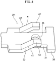
Fig. 4 is a perspective view showing a fixation portion of the terminal. -
Fig. 5A and Fig. 5B are views showing the fixation portion of the terminal,Fig. 5A being a plan view,Fig. 5B being a side view. - A
terminal 10, and amounting structure 100 between theterminal 10 and a mounting surface BS will be described below with reference to the drawings. In the following description, for convenience of explanation, "front/rear direction", "width direction", "thickness direction", "front", "rear", "left", "right", "up" and "down" are defined as shown in the drawings. "Front/rear direction", "left/right direction" and "up/down direction" cross one another. - As shown in
Fig. 1 to Fig. 3 , theterminal 10 according to the embodiment is connected to an end portion of anelectric wire 1. Theterminal 10 is, for example, mounted on a mounting surface BS of a vehicle body frame B of a vehicle such as an automobile so as to secure electric conduction thereto. Theelectric wire 1 is, for example, a ground wire for grounding various electric parts mounted on the vehicle. That is, theterminal 10 is a ground terminal to which theelectric wire 1 for ground has been connected. Theterminal 10 is fixed to astud bolt 61 by a washer 51 (fixture). Thestud bolt 61 is erectly provided on the mounting surface BS of the vehicle frame B of the vehicle. - The
electric wire 1 has aconductor core wire 2, and aninsulating coating 3 covering the circumference of theconductor core wire 2. Theconductor core wire 2 is constituted by a bundle of a plurality of strands made of copper, a copper alloy, aluminum, an aluminum alloy or the like. The insulatingcoating 3 is made of a resin material having flexibility and insulation. In the end portion of theelectric wire 1, theinsulating coating 3 is removed to exposed a part of theconductor core wire 2. - The
terminal 10 has an electricwire connection portion 20 and afixation portion 30. Theterminal 10 is, for example, manufactured by press working on a plate made of an electrically conductive metal material such as stainless steel, copper, or a copper alloy. - The electric
wire connection portion 20 has aconductor crimping portion 21, and acoating crimping portion 22. Theconductor crimping portion 21 has a pair ofconductor crimping pieces 21a, and thecoating crimping portion 22 has a pair ofcoating crimping pieces 22a. In the electricwire connection portion 20, theconductor crimping pieces 21a are fixed to theconductor core wire 2 of theelectric wire 1 by crimping, and thecoating crimping pieces 22a are fixed to the insulatingcoating 3 of theelectric wire 1 by crimping. Thus, theterminal 10 and theelectric wire 1 are coupled with each other so as to secure electric conduction between theterminal 10 and theconductor core wire 2 of theelectric wire 1. - As shown in
Fig. 4 ,Fig. 5A and Fig. 5B , thefixation portion 30 of theterminal 10 is formed like a plate, including acontact portion 31, and a pair of arm portions 32 (elastic portions) connected to thecontact portion 31. - At the substantial center of the
contact portion 31, an insertion hole 35 (insertion portion) is provided. In addition, at a distal end of thecontact portion 31, anextension portion 36 is provided to be connected to thecontact portion 31 and expanded in the width direction (the illustrated up/down direction) from thecontact portion 31. The width-direction size a of theextension portion 36 is larger than the width-direction size b of a part of thecontact portion 31 where theinsertion hole 35 is provided. - The
arm portions 32 are provided in opposite edge portions of thecontact portion 31 in the width direction. Thearm portions 32 are coupled with the rear side (that is, the electricwire connection portion 20 side) of thecontact portion 31 so as to extend to the front side (that is, theextension portion 36 side) along the opposite edge portions of thecontact portion 31. Eacharm portion 32 has a cantilever-likeinclined piece portion 41 which is inclined upward and extends toward the front from the place where thearm portion 32 is coupled with thecontact portion 31. The distal end part of theinclined piece portion 41 is bent toward the front to from atouch portion 42 substantially parallel with thecontact portion 31. Thetouch portions 42 are disposed to hold theinsertion hole 35 formed in thecontact portion 31, therebetween in the width direction in planar view as shown inFig. 5A . In addition, in a state where the terminal 10 has not been mounted on the mounting surface BS, the top face of eachtouch portion 42 and the bottom face of thecontact portion 31 are separated by initial height H as shown inFig. 5B . - As shown in
Fig. 3 , thestud bolt 61 erectly provided on the mounting surface BS of the vehicle body frame B has a shape like a round bar slightly smaller in diameter than theinsertion hole 35 formed in thecontact portion 31 of the terminal 10. Aneck portion 62 further smaller in diameter than any other part of thestud bolt 61 is provided near the distal end portion of thestud bolt 61. The lower-side (that is, mounting surface BS side) side face of theneck portion 62 and the mounting surface BS are separated from each other by height h. The height h is smaller than the initial height H of the top face of eachtouch portion 42. That is, the relation "initial height H > height h" is established. - The
washer 51 is, for example, formed out of a metal plate. Aretention hole portion 52 having a substantially circular shape is provided in a central portion of thewasher 51. The inner diameter of theretention hole portion 52 is smaller than the outer diameter of thestud bolt 61 and slightly larger than the outer diameter of theneck portion 62. Thewasher 51 has anotch portion 53 communicating with theretention hole portion 52 through one circumferential place. The width of thenotch portion 53 is slightly smaller than the outer diameter of theneck portion 62 of thestud bolt 61. - In order to mount the terminal 10 on the vehicle body frame B, the
stud bolt 61 is first inserted into theinsertion hole 35 of thecontact portion 31 in a state where the bottom face of thecontact portion 31 has been set to face the mounting surface BS of the vehicle body frame B. Then the terminal 10 is made close to the mounting surface BS until the bottom face of thecontact portion 31 of the terminal 10 abuts against the mounting surface BS. At this time, the top face (initial height H) of eachtouch portion 42 is located above the lower face (height h) of theneck portion 62. - Next, as shown in
Fig. 2 , thewasher 51 is fitted to theneck portion 62 from the rear side in a state where thenotch portion 53 has been set to face theneck portion 62 of thestud bolt 61 inserted into theinsertion hole 35 of thecontact portion 31. Thus, thenotch portion 53 of thewasher 51 is expanded by theneck portion 62 while theneck portion 62 passing through thenotch portion 53 enters into theretention hole portion 52. As a result, thewasher 51 is engaged with theneck portion 62 in the state where theneck portion 62 of thestud bolt 61 has entered into theretention hole portion 52 of thewasher 51. - Here, since the height h of the lower face of the
neck portion 62 is smaller than the initial height H of the top face of eachtouch portion 42, thewasher 51 touches thetouch portions 42 of thearm portions 32 when thewasher 51 is engaged with thestud bolt 61. When thewasher 51 is further inserted toward theneck portion 62, thewasher 51 deforms thearm portions 32 downward elastically. Then, due to urging force applied to thecontact portion 31 by thearm portions 32, thecontact portion 31 is pressed against the mounting surface BS. Thus, the terminal 10 is mounted on the vehicle body frame B while keeping itself in close contact with the mounting surface BS. Thus, electric conduction is established between theconductor core wire 2 of theelectric wire 1 and the vehicle body frame B. In order to secure proper electric conduction, the difference between the initial height H and the height h (=H-h) can be determined by various experiments in advance so that the urging force with which thearm portions 32 press thecontact portion 31 against the mounting surface BS exceeds a predetermined threshold to secure the reliability of electric connection. - The mounting
structure 100 between the terminal 10 and the mounting surface BS is completed through the aforementioned process. - In order to remove the terminal 10 mounted on the mounting surface BS, the
washer 51 engaged with theneck portion 62 of thestud bolt 61 is separated from thestud bolt 61 while sliding to the front. After that, thecontact portion 31 is extracted from thestud bolt 61. In this manner, the terminal 10 can be removed from the mounting surface BS easily. - As described above, according to the terminal 10 and the mounting
structure 100 of the terminal 10 according to the present embodiment, thewasher 51 is engaged with thestud bolt 61 erectly provided on the mounting surface BS in the state where thestud bolt 61 has been inserted into theinsertion portion 35 of thecontact portion 31, so that thearm portions 32 touching thewasher 51 urges thecontact portion 31 toward the mounting surface BS. Thus, the terminal 10 is mounted on the mounting surface BS in the state where thecontact portion 31 has been pressed against the mounting surface BS. Thus, the terminal 10 can be mounted on the mounting surface BS by the engagement of thewasher 51 with thestud bolt 61 without requiring fastening work using a bolt or the like. Further, the reliability of electric connection can be secured as long as the urging force with which thearm portions 32 press thecontact portion 31 against the mounting surface BS exceeds the threshold value. Accordingly, excessive dimensional accuracy is not required in the terminal 10, and torque control during the mounting can be also omitted. Thus, the terminal 10 can reduce the man-hours or the cost in use in comparison with a background-art terminal 10. - Further, the plurality of
arm portions 32 are disposed to hold therebetween theinsertion portion 35 provided in thecontact portion 31. Accordingly, due to the urging force applied to thecontact portion 31 by the plurality ofarm portions 32 individually, the inclination or floating of thecontact portion 31 around the insertion portion 35 (that is, around the stud bolt 61) can be inhibited. As a result, the contact area with the mounting surface BS can be suppressed from decreasing due to the inclination or the like of thecontact portion 31, so that the reliability of electric connection between the terminal 10 and the mounting surface BS can be further improved. - Furthermore, the aforementioned inclination or the like of the
contact portion 31 can be further firmly suppressed by theextension portion 36 expanded in the width direction (that is, in the direction in which the plurality ofarm portions 32 hold theinsertion portion 35 therebetween) from thecontact portion 31. Accordingly, the terminal 10 can bring thecontact portion 31 into more proper contact with the mounting surface BS so that the reliability of the electric connection can be further improved. - The foregoing description of the exemplary embodiments of the present invention has been provided for the purposes of illustration and description. It is not intended to be exhaustive or to limit the invention to the precise forms disclosed. Obviously, many modifications and variations will be apparent to practitioners skilled in the art. The embodiments were chosen and described in order to best explain the principles of the invention and its practical applications, thereby enabling others skilled in the art to understand the invention for various embodiments and with the various modifications as are suited to the particular use contemplated. It is intended that the scope of the invention be defined by the following claims and their equivalents.
- For example, the terminal 10 is used as a ground terminal in the aforementioned embodiment. However, the terminal 10 does not have to be used as a ground terminal, but may be, for example, used as a power terminal for feeding electric power to various electric parts.
- Further, the terminal 10 may have a notch-like insertion portion in the
contact portion 31 in place of theinsertion hole 35. That is, as long as the terminal 10 has an insertion portion allowing a stud bolt to be inserted thereto in the thickness direction, the terminal 10 is not particularly limited as to having the specific shape of the insertion portion or the like. Further, the insertion portion may be provided at a different place from thecontact portion 31. In addition, the terminal 10 may have an elastic portion like a double-supported beam in place of the cantilever-like arm portions 32, or may have a coil-like spring extending upward from the top face of thecontact portion 31. That is, as long as the terminal 10 has an elastic portion capable of touching thewasher 51 to generate urging force, the terminal 10 is not particularly limited as to having the specific shape of the elastic portion or the like. In the same manner, as long as thewasher 51 functions as a fixture capable of touching the terminal 10 to deform the elastic portion when thewasher 51 is engaged with thestud bolt 61, thewasher 51 is not particularly limited as to its specific shape or the like. In the same manner, the engagement portion (neck portion 62) allowing thewasher 51 to be engaged with thestud bolt 61 is not particularly limited as to its specific shape or the like. - Further, in the aforementioned embodiment, the
contact portion 31 is used as a main electric contact with the mounting surface BS, and thearm portions 32 can leave the mounting surface BS and touch thewasher 51. However, for example, contrary to the aforementioned embodiment, the arms portion 32 (particularly thetouch portions 42 which are free ends of the arm portions 32) may be used as electric contacts with the mounting surface BS. In this case, the terminal 10 and the mounting surface BS are assembled so that thecontact portion 31 can leave the mounting surface BS to touch thewasher 51. - According to the above exemplary embodiments, the terminal (10) is to be mounted on a mounting surface (BS) having a stud bolt (61) standing on the mounting surface (BS), the terminal comprising:
- a contact portion (31) configured to contact with the mounting surface (BS);
- an insertion portion (35) allowing the stud bolt (61) to be inserted to the insertion portion (35); and
- an elastic portion (32) connected to the contact portion (31) and extending in a direction to leave the mounting surface (BS), the elastic portion (32) being configured to urge the contact portion (31) elastically toward the mounting surface (BS) upon the terminal touching a fixture (51) engaged with the stud bolt (61).
- According to the terminal having the aforementioned configuration, when the stud bolt erectly provided on the mounting surface is engaged with the fixture (such as a washer) in use of the terminal in a state where the stud bolt has been inserted into the insertion portion, the terminal touches the fixture so that the elastic portion urges the contact portion elastically toward the mounting surface. Thus, the terminal is mounted on the mounting surface in a state where the contact portion has been pressed against the mounting surface. Accordingly, the terminal can be mounted on the mounting surface by the engagement of the fixture, such as a washer which is generally used, with the stud bolt without requiring fastening work using a bolt or the like. Further, the reliability of electric connection can be secured as long as the urging force with which the elastic portion presses the contact portion against the mounting surface (corresponding to fastening torque in case of fastening with a bolt) exceeds a predetermined threshold value. Accordingly, excessive dimensional accuracy is not required in the terminal, and torque control during the mounting can be also omitted. Thus, the terminal according to the configuration can reduce the man-hours or the cost in use in comparison with a background-art terminal.
- The aforementioned terminal may further comprising a plurality of the elastic portions (32),
the insertion portion (35) is provided in the contact portion (31), and one of the plurality of the elastic portions (32) and another of the plurality of the elastic portions (32) are located to sandwich the insertion portion (35) in a predetermined direction. - According to the terminal having the aforementioned configuration, the plurality of elastic portions are disposed to hold therebetween the insertion portion provided in the contact portion. Accordingly, due to the urging force applied to the contact portion by the plurality of elastic portions individually, the inclination or floating of the contact portion around the insertion portion (that is, around the stud bolt) can be inhibited. As a result, the contact area with the mounting surface can be suppressed from decreasing due to the inclination or the like of the contact portion, so that the reliability of electric connection between the terminal and the mounting surface can be further improved.
- The aforementioned terminal may further comprising an extension portion (36) extended from the contact portion (31) in the predetermined direction to contact with the mounting surface (BS).
- According to the terminal having the aforementioned configuration, the aforementioned inclination or the like of the contact portion can be further firmly suppressed by the extension portion expanded in the predetermined direction (that is, in the direction in which the plurality of elastic portions hold the insertion portion therebetween) from the contact portion. Accordingly, the terminal having the configuration can bring the contact portion into more proper contact with the mounting surface so that the reliability of the electric connection can be further improved.
- According to the above exemplary embodiments, a mounting structure (100) of a terminal and a mounting surface (BS), comprising:
- a mounting surface (BS) having a stud bolt (61) standing on the mounting surface (BS); and a terminal mounted on the mounting surface (BS),
- the terminal having a contact portion (31) contacting with the mounting surface (BS), an insertion portion (35) allowing the stud bolt (61) to be inserted to the insertion portion (35), and an elastic portion (32) connected to the contact portion (31) and extending in a direction to leave the mounting surface (BS),
- the contact portion (31) being elastically urged toward the mounting surface (BS) and pressed against the mounting surface (BS) due to the terminal touching a fixture (51) engaged with the stud bolt (61).
- According to the mounting structure between the terminal and the mounting surface, when the stud bolt erectly provided on the mounting surface is engaged with the fixture (such as a washer) in a state where the stud bolt has been inserted into the insertion portion, the terminal touches the fixture so that the elastic portion urges the contact portion elastically toward the mounting surface. Thus, the terminal is mounted on the mounting surface in a state where the contact portion has been pressed against the mounting surface. Accordingly, the terminal can be mounted on the mounting surface by the engagement of the fixture, such as a washer which is generally used, with the stud bolt without requiring fastening work using a bolt or the like. Further, the reliability of electric connection can be secured as long as the urging force with which the elastic portion presses the contact portion against the mounting surface (corresponding to fastening torque in case of fastening with a bolt) exceeds a predetermined threshold value. Accordingly, excessive dimensional accuracy is not required in the terminal, the stud bolt and the fixture, and torque control during the mounting can be also omitted. Thus, the mounting structure having the configuration can reduce the man-hours or the cost in use in comparison with a mounting structure with a background-art terminal.
- According to the present invention, it is possible to provide a terminal capable of reducing the man-hours or the cost in use, and a mounting structure between the terminal and a mounting surface.
Claims (4)
- A terminal to be mounted on a mounting surface having a stud bolt standing on the mounting surface, the terminal comprising:a contact portion configured to contact with the mounting surface;an insertion portion allowing the stud bolt to be inserted to the insertion portion; andan elastic portion connected to the contact portion and extending in a direction to leave the mounting surface, the elastic portion being configured to urge the contact portion elastically toward the mounting surface upon the terminal touching a fixture engaged with the stud bolt.
- The terminal according to Claim 1, further comprising a plurality of the elastic portions,
the insertion portion is provided in the contact portion, and one of the plurality of the elastic portions and another of the plurality of the elastic portions are located to sandwich the insertion portion in a predetermined direction. - The terminal according to Claim 2, further comprising an extension portion extended from the contact portion in the predetermined direction to contact with the mounting surface.
- A mounting structure of a terminal and a mounting surface, the structure comprising:a mounting surface having a stud bolt standing on the mounting surface; and a terminal mounted on the mounting surface,the terminal having a contact portion contacting with the mounting surface, an insertion portion allowing the stud bolt to be inserted to the insertion portion, and an elastic portion connected to the contact portion and extending in a direction to leave the mounting surface,the contact portion being elastically urged toward the mounting surface and pressed against the mounting surface due to the terminal touching a fixture engaged with the stud bolt.
Applications Claiming Priority (1)
| Application Number | Priority Date | Filing Date | Title |
|---|---|---|---|
| JP2019179433A JP7092729B2 (en) | 2019-09-30 | 2019-09-30 | Terminal and assembly structure of terminal and mounted surface |
Publications (2)
| Publication Number | Publication Date |
|---|---|
| EP3799214A1 true EP3799214A1 (en) | 2021-03-31 |
| EP3799214B1 EP3799214B1 (en) | 2022-04-20 |
Family
ID=72708995
Family Applications (1)
| Application Number | Title | Priority Date | Filing Date |
|---|---|---|---|
| EP20198936.5A Active EP3799214B1 (en) | 2019-09-30 | 2020-09-29 | Mounting structure of terminal and mounting surface |
Country Status (4)
| Country | Link |
|---|---|
| US (1) | US11349231B2 (en) |
| EP (1) | EP3799214B1 (en) |
| JP (1) | JP7092729B2 (en) |
| CN (1) | CN112582815B (en) |
Families Citing this family (1)
| Publication number | Priority date | Publication date | Assignee | Title |
|---|---|---|---|---|
| JP7845964B2 (en) * | 2022-08-29 | 2026-04-14 | 矢崎総業株式会社 | Electrical junction box unit, fastening structure for wires with terminals, and wires with terminals |
Citations (4)
| Publication number | Priority date | Publication date | Assignee | Title |
|---|---|---|---|---|
| US4983133A (en) * | 1989-05-31 | 1991-01-08 | Scyoc William C Van | Electrical terminal with annular section |
| JPH09147934A (en) | 1995-11-22 | 1997-06-06 | Sumitomo Wiring Syst Ltd | Earth terminal mounting structure |
| WO2010012872A1 (en) * | 2008-07-29 | 2010-02-04 | Saint-Gobain Glass France | Female, male electric connector and electric connection using such a female and/or male electric connector |
| US20170229796A1 (en) * | 2016-02-08 | 2017-08-10 | Sumitomo Wiring Systems, Ltd. | Ground connection structure and ground terminal fitting |
Family Cites Families (10)
| Publication number | Priority date | Publication date | Assignee | Title |
|---|---|---|---|---|
| JPH0992358A (en) * | 1995-09-20 | 1997-04-04 | Sumitomo Wiring Syst Ltd | Mounting structure of earth terminal |
| JPH10284148A (en) * | 1997-04-04 | 1998-10-23 | Sumitomo Wiring Syst Ltd | Fixing member for earth terminal |
| JP3695898B2 (en) * | 1997-06-03 | 2005-09-14 | 住友電装株式会社 | Terminal assembly structure and assembly method |
| JP2000012111A (en) * | 1998-06-18 | 2000-01-14 | Sumitomo Wiring Syst Ltd | Terminal |
| US6939097B2 (en) * | 2002-11-21 | 2005-09-06 | Illinois Tool Works, Inc. | Ground washer |
| CN201556821U (en) * | 2009-11-03 | 2010-08-18 | 广东明家科技股份有限公司 | Swinging member of power conducting terminal |
| US9178288B2 (en) | 2013-06-07 | 2015-11-03 | Apple Inc. | Spring plate for attaching bus bar to a printed circuit board |
| US11031904B2 (en) * | 2014-12-11 | 2021-06-08 | A.K. Stamping Company, Inc. | Grounding clamps |
| JP6262191B2 (en) * | 2015-12-09 | 2018-01-17 | 矢崎総業株式会社 | Ground terminal and wire harness |
| JP2017139114A (en) * | 2016-02-03 | 2017-08-10 | 住友電装株式会社 | Grounding connection structure and grounding terminal fitting |
-
2019
- 2019-09-30 JP JP2019179433A patent/JP7092729B2/en active Active
-
2020
- 2020-09-29 EP EP20198936.5A patent/EP3799214B1/en active Active
- 2020-09-30 US US17/037,710 patent/US11349231B2/en active Active
- 2020-09-30 CN CN202011059566.3A patent/CN112582815B/en active Active
Patent Citations (4)
| Publication number | Priority date | Publication date | Assignee | Title |
|---|---|---|---|---|
| US4983133A (en) * | 1989-05-31 | 1991-01-08 | Scyoc William C Van | Electrical terminal with annular section |
| JPH09147934A (en) | 1995-11-22 | 1997-06-06 | Sumitomo Wiring Syst Ltd | Earth terminal mounting structure |
| WO2010012872A1 (en) * | 2008-07-29 | 2010-02-04 | Saint-Gobain Glass France | Female, male electric connector and electric connection using such a female and/or male electric connector |
| US20170229796A1 (en) * | 2016-02-08 | 2017-08-10 | Sumitomo Wiring Systems, Ltd. | Ground connection structure and ground terminal fitting |
Also Published As
| Publication number | Publication date |
|---|---|
| JP7092729B2 (en) | 2022-06-28 |
| CN112582815A (en) | 2021-03-30 |
| US11349231B2 (en) | 2022-05-31 |
| US20210098908A1 (en) | 2021-04-01 |
| JP2021057195A (en) | 2021-04-08 |
| EP3799214B1 (en) | 2022-04-20 |
| CN112582815B (en) | 2022-09-27 |
Similar Documents
| Publication | Publication Date | Title |
|---|---|---|
| US5897406A (en) | Electrical terminal for glass sheets | |
| EP3584889B1 (en) | Connector device | |
| US7344422B2 (en) | Electrical component, in particular relay socket, having spring clamps, and method for the manufacture thereof | |
| US9444205B2 (en) | Electric connector with contact protection | |
| US8398442B2 (en) | Terminal fitting and a method for assembling the same | |
| CN103840319B (en) | Ground terminal and the connector using the ground terminal | |
| EP2847831B1 (en) | Connector | |
| US9136614B2 (en) | Conductor connection tool and relay unit using the same | |
| US9502795B1 (en) | Clamping wire structure of terminal block | |
| US5135417A (en) | Dual usage electrical/electronic pin terminal system | |
| CN110994504A (en) | Electrical connection box and its ground connection structure | |
| EP3407428B1 (en) | Metal leaf spring structure of electrical connection terminal | |
| EP3799214B1 (en) | Mounting structure of terminal and mounting surface | |
| JP5790130B2 (en) | connector | |
| US20160120024A1 (en) | Linear Conductor Connection Terminal | |
| US10403999B2 (en) | Terminal fitting, and connector | |
| US20190157788A1 (en) | Terminal fitting and connector | |
| KR920008687Y1 (en) | Horn switch of steering wheel | |
| JP2014529867A (en) | Stamped and bent contacts | |
| US9419349B2 (en) | Coaxial cable connector having a fastener and anti-rotation projections | |
| EP1583191B1 (en) | High retention connection | |
| KR101533808B1 (en) | Connector | |
| US11670877B2 (en) | Grounding clamp with lateral anti-twist protection | |
| EP3588678B1 (en) | Connection structure of cable and terminal | |
| JP2005071892A (en) | L-type connector |
Legal Events
| Date | Code | Title | Description |
|---|---|---|---|
| PUAI | Public reference made under article 153(3) epc to a published international application that has entered the european phase |
Free format text: ORIGINAL CODE: 0009012 |
|
| STAA | Information on the status of an ep patent application or granted ep patent |
Free format text: STATUS: REQUEST FOR EXAMINATION WAS MADE |
|
| 17P | Request for examination filed |
Effective date: 20200929 |
|
| AK | Designated contracting states |
Kind code of ref document: A1 Designated state(s): AL AT BE BG CH CY CZ DE DK EE ES FI FR GB GR HR HU IE IS IT LI LT LU LV MC MK MT NL NO PL PT RO RS SE SI SK SM TR |
|
| AX | Request for extension of the european patent |
Extension state: BA ME |
|
| STAA | Information on the status of an ep patent application or granted ep patent |
Free format text: STATUS: EXAMINATION IS IN PROGRESS |
|
| 17Q | First examination report despatched |
Effective date: 20210827 |
|
| GRAP | Despatch of communication of intention to grant a patent |
Free format text: ORIGINAL CODE: EPIDOSNIGR1 |
|
| STAA | Information on the status of an ep patent application or granted ep patent |
Free format text: STATUS: GRANT OF PATENT IS INTENDED |
|
| INTG | Intention to grant announced |
Effective date: 20220131 |
|
| GRAS | Grant fee paid |
Free format text: ORIGINAL CODE: EPIDOSNIGR3 |
|
| GRAA | (expected) grant |
Free format text: ORIGINAL CODE: 0009210 |
|
| STAA | Information on the status of an ep patent application or granted ep patent |
Free format text: STATUS: THE PATENT HAS BEEN GRANTED |
|
| AK | Designated contracting states |
Kind code of ref document: B1 Designated state(s): AL AT BE BG CH CY CZ DE DK EE ES FI FR GB GR HR HU IE IS IT LI LT LU LV MC MK MT NL NO PL PT RO RS SE SI SK SM TR |
|
| REG | Reference to a national code |
Ref country code: GB Ref legal event code: FG4D |
|
| REG | Reference to a national code |
Ref country code: CH Ref legal event code: EP |
|
| REG | Reference to a national code |
Ref country code: IE Ref legal event code: FG4D |
|
| REG | Reference to a national code |
Ref country code: DE Ref legal event code: R096 Ref document number: 602020002754 Country of ref document: DE |
|
| REG | Reference to a national code |
Ref country code: AT Ref legal event code: REF Ref document number: 1485934 Country of ref document: AT Kind code of ref document: T Effective date: 20220515 |
|
| REG | Reference to a national code |
Ref country code: LT Ref legal event code: MG9D |
|
| REG | Reference to a national code |
Ref country code: NL Ref legal event code: MP Effective date: 20220420 |
|
| REG | Reference to a national code |
Ref country code: AT Ref legal event code: MK05 Ref document number: 1485934 Country of ref document: AT Kind code of ref document: T Effective date: 20220420 |
|
| PG25 | Lapsed in a contracting state [announced via postgrant information from national office to epo] |
Ref country code: NL Free format text: LAPSE BECAUSE OF FAILURE TO SUBMIT A TRANSLATION OF THE DESCRIPTION OR TO PAY THE FEE WITHIN THE PRESCRIBED TIME-LIMIT Effective date: 20220420 |
|
| PG25 | Lapsed in a contracting state [announced via postgrant information from national office to epo] |
Ref country code: SE Free format text: LAPSE BECAUSE OF FAILURE TO SUBMIT A TRANSLATION OF THE DESCRIPTION OR TO PAY THE FEE WITHIN THE PRESCRIBED TIME-LIMIT Effective date: 20220420 Ref country code: PT Free format text: LAPSE BECAUSE OF FAILURE TO SUBMIT A TRANSLATION OF THE DESCRIPTION OR TO PAY THE FEE WITHIN THE PRESCRIBED TIME-LIMIT Effective date: 20220822 Ref country code: NO Free format text: LAPSE BECAUSE OF FAILURE TO SUBMIT A TRANSLATION OF THE DESCRIPTION OR TO PAY THE FEE WITHIN THE PRESCRIBED TIME-LIMIT Effective date: 20220720 Ref country code: LT Free format text: LAPSE BECAUSE OF FAILURE TO SUBMIT A TRANSLATION OF THE DESCRIPTION OR TO PAY THE FEE WITHIN THE PRESCRIBED TIME-LIMIT Effective date: 20220420 Ref country code: HR Free format text: LAPSE BECAUSE OF FAILURE TO SUBMIT A TRANSLATION OF THE DESCRIPTION OR TO PAY THE FEE WITHIN THE PRESCRIBED TIME-LIMIT Effective date: 20220420 Ref country code: GR Free format text: LAPSE BECAUSE OF FAILURE TO SUBMIT A TRANSLATION OF THE DESCRIPTION OR TO PAY THE FEE WITHIN THE PRESCRIBED TIME-LIMIT Effective date: 20220721 Ref country code: FI Free format text: LAPSE BECAUSE OF FAILURE TO SUBMIT A TRANSLATION OF THE DESCRIPTION OR TO PAY THE FEE WITHIN THE PRESCRIBED TIME-LIMIT Effective date: 20220420 Ref country code: ES Free format text: LAPSE BECAUSE OF FAILURE TO SUBMIT A TRANSLATION OF THE DESCRIPTION OR TO PAY THE FEE WITHIN THE PRESCRIBED TIME-LIMIT Effective date: 20220420 Ref country code: BG Free format text: LAPSE BECAUSE OF FAILURE TO SUBMIT A TRANSLATION OF THE DESCRIPTION OR TO PAY THE FEE WITHIN THE PRESCRIBED TIME-LIMIT Effective date: 20220720 Ref country code: AT Free format text: LAPSE BECAUSE OF FAILURE TO SUBMIT A TRANSLATION OF THE DESCRIPTION OR TO PAY THE FEE WITHIN THE PRESCRIBED TIME-LIMIT Effective date: 20220420 |
|
| PG25 | Lapsed in a contracting state [announced via postgrant information from national office to epo] |
Ref country code: RS Free format text: LAPSE BECAUSE OF FAILURE TO SUBMIT A TRANSLATION OF THE DESCRIPTION OR TO PAY THE FEE WITHIN THE PRESCRIBED TIME-LIMIT Effective date: 20220420 Ref country code: PL Free format text: LAPSE BECAUSE OF FAILURE TO SUBMIT A TRANSLATION OF THE DESCRIPTION OR TO PAY THE FEE WITHIN THE PRESCRIBED TIME-LIMIT Effective date: 20220420 Ref country code: LV Free format text: LAPSE BECAUSE OF FAILURE TO SUBMIT A TRANSLATION OF THE DESCRIPTION OR TO PAY THE FEE WITHIN THE PRESCRIBED TIME-LIMIT Effective date: 20220420 Ref country code: IS Free format text: LAPSE BECAUSE OF FAILURE TO SUBMIT A TRANSLATION OF THE DESCRIPTION OR TO PAY THE FEE WITHIN THE PRESCRIBED TIME-LIMIT Effective date: 20220820 |
|
| REG | Reference to a national code |
Ref country code: DE Ref legal event code: R097 Ref document number: 602020002754 Country of ref document: DE |
|
| PG25 | Lapsed in a contracting state [announced via postgrant information from national office to epo] |
Ref country code: SM Free format text: LAPSE BECAUSE OF FAILURE TO SUBMIT A TRANSLATION OF THE DESCRIPTION OR TO PAY THE FEE WITHIN THE PRESCRIBED TIME-LIMIT Effective date: 20220420 Ref country code: SK Free format text: LAPSE BECAUSE OF FAILURE TO SUBMIT A TRANSLATION OF THE DESCRIPTION OR TO PAY THE FEE WITHIN THE PRESCRIBED TIME-LIMIT Effective date: 20220420 Ref country code: RO Free format text: LAPSE BECAUSE OF FAILURE TO SUBMIT A TRANSLATION OF THE DESCRIPTION OR TO PAY THE FEE WITHIN THE PRESCRIBED TIME-LIMIT Effective date: 20220420 Ref country code: EE Free format text: LAPSE BECAUSE OF FAILURE TO SUBMIT A TRANSLATION OF THE DESCRIPTION OR TO PAY THE FEE WITHIN THE PRESCRIBED TIME-LIMIT Effective date: 20220420 Ref country code: DK Free format text: LAPSE BECAUSE OF FAILURE TO SUBMIT A TRANSLATION OF THE DESCRIPTION OR TO PAY THE FEE WITHIN THE PRESCRIBED TIME-LIMIT Effective date: 20220420 Ref country code: CZ Free format text: LAPSE BECAUSE OF FAILURE TO SUBMIT A TRANSLATION OF THE DESCRIPTION OR TO PAY THE FEE WITHIN THE PRESCRIBED TIME-LIMIT Effective date: 20220420 |
|
| PLBE | No opposition filed within time limit |
Free format text: ORIGINAL CODE: 0009261 |
|
| STAA | Information on the status of an ep patent application or granted ep patent |
Free format text: STATUS: NO OPPOSITION FILED WITHIN TIME LIMIT |
|
| 26N | No opposition filed |
Effective date: 20230123 |
|
| PG25 | Lapsed in a contracting state [announced via postgrant information from national office to epo] |
Ref country code: AL Free format text: LAPSE BECAUSE OF FAILURE TO SUBMIT A TRANSLATION OF THE DESCRIPTION OR TO PAY THE FEE WITHIN THE PRESCRIBED TIME-LIMIT Effective date: 20220420 |
|
| PG25 | Lapsed in a contracting state [announced via postgrant information from national office to epo] |
Ref country code: MC Free format text: LAPSE BECAUSE OF FAILURE TO SUBMIT A TRANSLATION OF THE DESCRIPTION OR TO PAY THE FEE WITHIN THE PRESCRIBED TIME-LIMIT Effective date: 20220420 |
|
| REG | Reference to a national code |
Ref country code: BE Ref legal event code: MM Effective date: 20220930 |
|
| PG25 | Lapsed in a contracting state [announced via postgrant information from national office to epo] |
Ref country code: SI Free format text: LAPSE BECAUSE OF FAILURE TO SUBMIT A TRANSLATION OF THE DESCRIPTION OR TO PAY THE FEE WITHIN THE PRESCRIBED TIME-LIMIT Effective date: 20220420 |
|
| PG25 | Lapsed in a contracting state [announced via postgrant information from national office to epo] |
Ref country code: LU Free format text: LAPSE BECAUSE OF NON-PAYMENT OF DUE FEES Effective date: 20220929 |
|
| PG25 | Lapsed in a contracting state [announced via postgrant information from national office to epo] |
Ref country code: IE Free format text: LAPSE BECAUSE OF NON-PAYMENT OF DUE FEES Effective date: 20220929 Ref country code: FR Free format text: LAPSE BECAUSE OF NON-PAYMENT OF DUE FEES Effective date: 20220930 |
|
| PG25 | Lapsed in a contracting state [announced via postgrant information from national office to epo] |
Ref country code: BE Free format text: LAPSE BECAUSE OF NON-PAYMENT OF DUE FEES Effective date: 20220930 |
|
| PG25 | Lapsed in a contracting state [announced via postgrant information from national office to epo] |
Ref country code: IT Free format text: LAPSE BECAUSE OF FAILURE TO SUBMIT A TRANSLATION OF THE DESCRIPTION OR TO PAY THE FEE WITHIN THE PRESCRIBED TIME-LIMIT Effective date: 20220420 |
|
| PG25 | Lapsed in a contracting state [announced via postgrant information from national office to epo] |
Ref country code: CY Free format text: LAPSE BECAUSE OF FAILURE TO SUBMIT A TRANSLATION OF THE DESCRIPTION OR TO PAY THE FEE WITHIN THE PRESCRIBED TIME-LIMIT Effective date: 20220420 |
|
| REG | Reference to a national code |
Ref country code: CH Ref legal event code: PL |
|
| PG25 | Lapsed in a contracting state [announced via postgrant information from national office to epo] |
Ref country code: MK Free format text: LAPSE BECAUSE OF FAILURE TO SUBMIT A TRANSLATION OF THE DESCRIPTION OR TO PAY THE FEE WITHIN THE PRESCRIBED TIME-LIMIT Effective date: 20220420 |
|
| PG25 | Lapsed in a contracting state [announced via postgrant information from national office to epo] |
Ref country code: CH Free format text: LAPSE BECAUSE OF NON-PAYMENT OF DUE FEES Effective date: 20230930 |
|
| PG25 | Lapsed in a contracting state [announced via postgrant information from national office to epo] |
Ref country code: HU Free format text: LAPSE BECAUSE OF FAILURE TO SUBMIT A TRANSLATION OF THE DESCRIPTION OR TO PAY THE FEE WITHIN THE PRESCRIBED TIME-LIMIT; INVALID AB INITIO Effective date: 20200929 Ref country code: CH Free format text: LAPSE BECAUSE OF NON-PAYMENT OF DUE FEES Effective date: 20230930 |
|
| PG25 | Lapsed in a contracting state [announced via postgrant information from national office to epo] |
Ref country code: MT Free format text: LAPSE BECAUSE OF FAILURE TO SUBMIT A TRANSLATION OF THE DESCRIPTION OR TO PAY THE FEE WITHIN THE PRESCRIBED TIME-LIMIT Effective date: 20220420 |
|
| PG25 | Lapsed in a contracting state [announced via postgrant information from national office to epo] |
Ref country code: BG Free format text: LAPSE BECAUSE OF FAILURE TO SUBMIT A TRANSLATION OF THE DESCRIPTION OR TO PAY THE FEE WITHIN THE PRESCRIBED TIME-LIMIT Effective date: 20220420 |
|
| PG25 | Lapsed in a contracting state [announced via postgrant information from national office to epo] |
Ref country code: BG Free format text: LAPSE BECAUSE OF FAILURE TO SUBMIT A TRANSLATION OF THE DESCRIPTION OR TO PAY THE FEE WITHIN THE PRESCRIBED TIME-LIMIT Effective date: 20220420 |
|
| GBPC | Gb: european patent ceased through non-payment of renewal fee |
Effective date: 20240929 |
|
| PG25 | Lapsed in a contracting state [announced via postgrant information from national office to epo] |
Ref country code: GB Free format text: LAPSE BECAUSE OF NON-PAYMENT OF DUE FEES Effective date: 20240929 |
|
| PGFP | Annual fee paid to national office [announced via postgrant information from national office to epo] |
Ref country code: DE Payment date: 20250805 Year of fee payment: 6 |
|
| PG25 | Lapsed in a contracting state [announced via postgrant information from national office to epo] |
Ref country code: TR Free format text: LAPSE BECAUSE OF FAILURE TO SUBMIT A TRANSLATION OF THE DESCRIPTION OR TO PAY THE FEE WITHIN THE PRESCRIBED TIME-LIMIT Effective date: 20220420 |