EP3799188A1 - Storage battery container - Google Patents
Storage battery container Download PDFInfo
- Publication number
- EP3799188A1 EP3799188A1 EP20771076.5A EP20771076A EP3799188A1 EP 3799188 A1 EP3799188 A1 EP 3799188A1 EP 20771076 A EP20771076 A EP 20771076A EP 3799188 A1 EP3799188 A1 EP 3799188A1
- Authority
- EP
- European Patent Office
- Prior art keywords
- air
- storage battery
- air exhaust
- heat dissipation
- dissipation device
- Prior art date
- Legal status (The legal status is an assumption and is not a legal conclusion. Google has not performed a legal analysis and makes no representation as to the accuracy of the status listed.)
- Pending
Links
Images




Classifications
-
- H—ELECTRICITY
- H01—ELECTRIC ELEMENTS
- H01M—PROCESSES OR MEANS, e.g. BATTERIES, FOR THE DIRECT CONVERSION OF CHEMICAL ENERGY INTO ELECTRICAL ENERGY
- H01M10/00—Secondary cells; Manufacture thereof
- H01M10/60—Heating or cooling; Temperature control
- H01M10/65—Means for temperature control structurally associated with the cells
- H01M10/656—Means for temperature control structurally associated with the cells characterised by the type of heat-exchange fluid
- H01M10/6561—Gases
- H01M10/6566—Means within the gas flow to guide the flow around one or more cells, e.g. manifolds, baffles or other barriers
-
- H—ELECTRICITY
- H01—ELECTRIC ELEMENTS
- H01M—PROCESSES OR MEANS, e.g. BATTERIES, FOR THE DIRECT CONVERSION OF CHEMICAL ENERGY INTO ELECTRICAL ENERGY
- H01M10/00—Secondary cells; Manufacture thereof
- H01M10/60—Heating or cooling; Temperature control
- H01M10/61—Types of temperature control
- H01M10/613—Cooling or keeping cold
-
- H—ELECTRICITY
- H01—ELECTRIC ELEMENTS
- H01M—PROCESSES OR MEANS, e.g. BATTERIES, FOR THE DIRECT CONVERSION OF CHEMICAL ENERGY INTO ELECTRICAL ENERGY
- H01M10/00—Secondary cells; Manufacture thereof
- H01M10/60—Heating or cooling; Temperature control
- H01M10/61—Types of temperature control
- H01M10/615—Heating or keeping warm
-
- H—ELECTRICITY
- H01—ELECTRIC ELEMENTS
- H01M—PROCESSES OR MEANS, e.g. BATTERIES, FOR THE DIRECT CONVERSION OF CHEMICAL ENERGY INTO ELECTRICAL ENERGY
- H01M10/00—Secondary cells; Manufacture thereof
- H01M10/60—Heating or cooling; Temperature control
- H01M10/61—Types of temperature control
- H01M10/617—Types of temperature control for achieving uniformity or desired distribution of temperature
-
- H—ELECTRICITY
- H01—ELECTRIC ELEMENTS
- H01M—PROCESSES OR MEANS, e.g. BATTERIES, FOR THE DIRECT CONVERSION OF CHEMICAL ENERGY INTO ELECTRICAL ENERGY
- H01M10/00—Secondary cells; Manufacture thereof
- H01M10/60—Heating or cooling; Temperature control
- H01M10/62—Heating or cooling; Temperature control specially adapted for specific applications
- H01M10/627—Stationary installations, e.g. power plant buffering or backup power supplies
-
- H—ELECTRICITY
- H01—ELECTRIC ELEMENTS
- H01M—PROCESSES OR MEANS, e.g. BATTERIES, FOR THE DIRECT CONVERSION OF CHEMICAL ENERGY INTO ELECTRICAL ENERGY
- H01M10/00—Secondary cells; Manufacture thereof
- H01M10/60—Heating or cooling; Temperature control
- H01M10/65—Means for temperature control structurally associated with the cells
- H01M10/655—Solid structures for heat exchange or heat conduction
- H01M10/6551—Surfaces specially adapted for heat dissipation or radiation, e.g. fins or coatings
-
- H—ELECTRICITY
- H01—ELECTRIC ELEMENTS
- H01M—PROCESSES OR MEANS, e.g. BATTERIES, FOR THE DIRECT CONVERSION OF CHEMICAL ENERGY INTO ELECTRICAL ENERGY
- H01M10/00—Secondary cells; Manufacture thereof
- H01M10/60—Heating or cooling; Temperature control
- H01M10/65—Means for temperature control structurally associated with the cells
- H01M10/656—Means for temperature control structurally associated with the cells characterised by the type of heat-exchange fluid
- H01M10/6561—Gases
-
- H—ELECTRICITY
- H01—ELECTRIC ELEMENTS
- H01M—PROCESSES OR MEANS, e.g. BATTERIES, FOR THE DIRECT CONVERSION OF CHEMICAL ENERGY INTO ELECTRICAL ENERGY
- H01M10/00—Secondary cells; Manufacture thereof
- H01M10/60—Heating or cooling; Temperature control
- H01M10/65—Means for temperature control structurally associated with the cells
- H01M10/656—Means for temperature control structurally associated with the cells characterised by the type of heat-exchange fluid
- H01M10/6561—Gases
- H01M10/6563—Gases with forced flow, e.g. by blowers
-
- H—ELECTRICITY
- H01—ELECTRIC ELEMENTS
- H01M—PROCESSES OR MEANS, e.g. BATTERIES, FOR THE DIRECT CONVERSION OF CHEMICAL ENERGY INTO ELECTRICAL ENERGY
- H01M10/00—Secondary cells; Manufacture thereof
- H01M10/60—Heating or cooling; Temperature control
- H01M10/65—Means for temperature control structurally associated with the cells
- H01M10/659—Means for temperature control structurally associated with the cells by heat storage or buffering, e.g. heat capacity or liquid-solid phase changes or transition
-
- H—ELECTRICITY
- H01—ELECTRIC ELEMENTS
- H01M—PROCESSES OR MEANS, e.g. BATTERIES, FOR THE DIRECT CONVERSION OF CHEMICAL ENERGY INTO ELECTRICAL ENERGY
- H01M50/00—Constructional details or processes of manufacture of the non-active parts of electrochemical cells other than fuel cells, e.g. hybrid cells
- H01M50/20—Mountings; Secondary casings or frames; Racks, modules or packs; Suspension devices; Shock absorbers; Transport or carrying devices; Holders
- H01M50/204—Racks, modules or packs for multiple batteries or multiple cells
- H01M50/207—Racks, modules or packs for multiple batteries or multiple cells characterised by their shape
- H01M50/209—Racks, modules or packs for multiple batteries or multiple cells characterised by their shape adapted for prismatic or rectangular cells
-
- H—ELECTRICITY
- H01—ELECTRIC ELEMENTS
- H01M—PROCESSES OR MEANS, e.g. BATTERIES, FOR THE DIRECT CONVERSION OF CHEMICAL ENERGY INTO ELECTRICAL ENERGY
- H01M10/00—Secondary cells; Manufacture thereof
- H01M10/36—Accumulators not provided for in groups H01M10/05-H01M10/34
- H01M10/39—Accumulators not provided for in groups H01M10/05-H01M10/34 working at high temperature
- H01M10/3909—Sodium-sulfur cells
-
- H—ELECTRICITY
- H01—ELECTRIC ELEMENTS
- H01M—PROCESSES OR MEANS, e.g. BATTERIES, FOR THE DIRECT CONVERSION OF CHEMICAL ENERGY INTO ELECTRICAL ENERGY
- H01M10/00—Secondary cells; Manufacture thereof
- H01M10/60—Heating or cooling; Temperature control
- H01M10/63—Control systems
-
- H—ELECTRICITY
- H01—ELECTRIC ELEMENTS
- H01M—PROCESSES OR MEANS, e.g. BATTERIES, FOR THE DIRECT CONVERSION OF CHEMICAL ENERGY INTO ELECTRICAL ENERGY
- H01M10/00—Secondary cells; Manufacture thereof
- H01M10/60—Heating or cooling; Temperature control
- H01M10/65—Means for temperature control structurally associated with the cells
- H01M10/653—Means for temperature control structurally associated with the cells characterised by electrically insulating or thermally conductive materials
-
- H—ELECTRICITY
- H01—ELECTRIC ELEMENTS
- H01M—PROCESSES OR MEANS, e.g. BATTERIES, FOR THE DIRECT CONVERSION OF CHEMICAL ENERGY INTO ELECTRICAL ENERGY
- H01M10/00—Secondary cells; Manufacture thereof
- H01M10/60—Heating or cooling; Temperature control
- H01M10/65—Means for temperature control structurally associated with the cells
- H01M10/655—Solid structures for heat exchange or heat conduction
- H01M10/6556—Solid parts with flow channel passages or pipes for heat exchange
-
- H—ELECTRICITY
- H01—ELECTRIC ELEMENTS
- H01M—PROCESSES OR MEANS, e.g. BATTERIES, FOR THE DIRECT CONVERSION OF CHEMICAL ENERGY INTO ELECTRICAL ENERGY
- H01M10/00—Secondary cells; Manufacture thereof
- H01M10/60—Heating or cooling; Temperature control
- H01M10/65—Means for temperature control structurally associated with the cells
- H01M10/657—Means for temperature control structurally associated with the cells by electric or electromagnetic means
- H01M10/6571—Resistive heaters
-
- H—ELECTRICITY
- H01—ELECTRIC ELEMENTS
- H01M—PROCESSES OR MEANS, e.g. BATTERIES, FOR THE DIRECT CONVERSION OF CHEMICAL ENERGY INTO ELECTRICAL ENERGY
- H01M10/00—Secondary cells; Manufacture thereof
- H01M10/60—Heating or cooling; Temperature control
- H01M10/65—Means for temperature control structurally associated with the cells
- H01M10/658—Means for temperature control structurally associated with the cells by thermal insulation or shielding
-
- H—ELECTRICITY
- H01—ELECTRIC ELEMENTS
- H01M—PROCESSES OR MEANS, e.g. BATTERIES, FOR THE DIRECT CONVERSION OF CHEMICAL ENERGY INTO ELECTRICAL ENERGY
- H01M50/00—Constructional details or processes of manufacture of the non-active parts of electrochemical cells other than fuel cells, e.g. hybrid cells
- H01M50/20—Mountings; Secondary casings or frames; Racks, modules or packs; Suspension devices; Shock absorbers; Transport or carrying devices; Holders
- H01M50/204—Racks, modules or packs for multiple batteries or multiple cells
-
- H—ELECTRICITY
- H01—ELECTRIC ELEMENTS
- H01M—PROCESSES OR MEANS, e.g. BATTERIES, FOR THE DIRECT CONVERSION OF CHEMICAL ENERGY INTO ELECTRICAL ENERGY
- H01M50/00—Constructional details or processes of manufacture of the non-active parts of electrochemical cells other than fuel cells, e.g. hybrid cells
- H01M50/20—Mountings; Secondary casings or frames; Racks, modules or packs; Suspension devices; Shock absorbers; Transport or carrying devices; Holders
- H01M50/253—Mountings; Secondary casings or frames; Racks, modules or packs; Suspension devices; Shock absorbers; Transport or carrying devices; Holders adapted for specific cells, e.g. electrochemical cells operating at high temperature
-
- Y—GENERAL TAGGING OF NEW TECHNOLOGICAL DEVELOPMENTS; GENERAL TAGGING OF CROSS-SECTIONAL TECHNOLOGIES SPANNING OVER SEVERAL SECTIONS OF THE IPC; TECHNICAL SUBJECTS COVERED BY FORMER USPC CROSS-REFERENCE ART COLLECTIONS [XRACs] AND DIGESTS
- Y02—TECHNOLOGIES OR APPLICATIONS FOR MITIGATION OR ADAPTATION AGAINST CLIMATE CHANGE
- Y02E—REDUCTION OF GREENHOUSE GAS [GHG] EMISSIONS, RELATED TO ENERGY GENERATION, TRANSMISSION OR DISTRIBUTION
- Y02E60/00—Enabling technologies; Technologies with a potential or indirect contribution to GHG emissions mitigation
- Y02E60/10—Energy storage using batteries
Definitions
- frequency regulation of electric power systems and adjustment of power demand and power supply of electric power systems are achieved by using a plurality of power generators, storage batteries, and the like within the systems. Further, adjustment of difference between generated power and planned output power from natural energy power generators, and reduction of fluctuations in power generation from natural energy power generators, too, are often achieved by a plurality of power generators, storage batteries, and the like.
- Storage batteries are capable of changing output power at higher speeds as compared to common power generators, and are therefore effective to regulate frequencies of electric power systems, adjust the difference between generated power and planned output power from natural energy power generators, and to adjust power demand and power supply of electric power systems.
- NaS batteries sodium-sulfur batteries
- the NaS batteries are secondary batteries that have a configuration in which metallic sodium and sulfur as active materials are separated and encased in a solid electrolyte cylinder. Accordingly, when heated to high temperatures, NaS batteries generate certain energy through electrochemical reactions of the two active materials being melted.
- NaS batteries are used in the form of storage batteries in which a plurality of unit cells are assembled in an erected position and connected to each other (International Publication No. WO 2013/111426 ).
- the present invention has been devised in order to solve the problems above, and an object of the invention is to provide a storage battery container that can reduce discharge of heat from the storage batteries into the interior of the container (including a package, container device, etc.), and can improve the operating efficiency of the storage batteries, while enabling a simplified structure.
- FIGS. 1 to 9 An embodiment in which the storage battery container of the invention is applied to NaS batteries will be described referring to FIGS. 1 to 9 .
- container 10 Before describing the storage battery container of this embodiment (hereinafter referred to as container 10), a storage battery 12 that is accommodated in the container 10 (see FIG. 5 ) will be described referring to FIGS. 1 to 4 .
- the storage battery 12 includes a casing 18 accommodating a battery assembly 16 formed of a plurality of unit cells 14 (see FIG. 4 ), and a variable heat dissipation device 22 for maintaining the temperature in the casing 18 within a certain allowable range (operating temperature range) so as to achieve heat balance of heat accumulation within the casing 18.
- a temperature sensor 26 for measuring the present temperature in the casing 18 is further provided.
- the variable heat dissipation device 22 includes a heat dissipation control unit 28 that drives a fan for feeding air into the casing 18. This will be described later.
- the storage battery 12 includes a base 40 made of, e.g., a steel material, a box 42 placed and fixed on the base 40, the battery assembly 16 formed of a large number of unit cells 14 accommodated in the box 42, and a lid 44 closing the opening of the box 42.
- Each unit cell 14 is made in a cylindrical shape and accommodated within the box 42 in such a manner that its axial direction extends in a vertical direction.
- the box 42 and the lid 44 form the casing 18 of the storage battery 12.
- heaters 24, which are used to raise the temperature in the box 42 are provided on the bottom surface and inner wall surfaces of the box 42. Further, the space between the box 42 and the battery assembly 16 is filled with silica sand 46 for the purpose of transmitting heat from the heaters 24 to the unit cells 14 and absorbing heat generated from the unit cells 14.
- the box 42 has a substantially cuboid shape, for example, includes four side walls (a first side wall 68a, a second side wall 68b, a third side wall 68c, and a fourth side wall 68d: see FIG. 4 ) and a bottom wall, and has an opening at the top.
- the box 42 is formed of a plate material made of stainless steel, for example, and is shaped like a box having a hollow 48 in itself.
- the hollow 48 is an enclosed space that is airtightly sealed, and has a structure in which the hollow 48 and the outside space can communicate with each other through a vacuum valve not shown.
- the hollow 48 is filled with a porous, vacuum insulation board 50 that is made by solidifying glass fiber into a plate-like shape with adhesive, and so the box 42 has a vacuum heat insulation structure.
- the lid 44 has a top wall 52 and an awning 54, and is placed so as to close the opening at the top of the box 42.
- the lid 44 is also formed of a plate material made of stainless steel, for example, and is shaped like a box having a hollow 56 in itself.
- the hollow 56 is an enclosed space that is airtightly sealed, and has a structure in which the hollow 56 and the outside space can communicate with each other through a vacuum valve not shown.
- the hollow 56 is filled with a porous, vacuum insulation board 58 that is made by solidifying glass fiber into a plate-like shape with adhesive, and so the lid 44 has a vacuum heat insulation structure.
- the battery assembly 16 is formed of two or more blocks 64 that are connected in series from a positive outside terminal 60 to a negative outside terminal 62.
- Each block 64 includes two or more circuits (strings 66) connected in parallel, where each of the circuits is formed of two or more unit cells 14 connected in series.
- the positive outside terminal 60 protrudes outside through the first side wall 68a of the box 42
- the negative outside terminal 62 protrudes outside through the second side wall 68b of the box 42 (the side wall opposite to the first side wall 68a).
- variable heat dissipation device 22 includes a metal duct 72 which is provided at least between the box 42 and the lid 44 and through which air 70 flows, a plate member 74 provided between the battery assembly 16 and the duct 72 and having at least an electric insulating property, and a fan 76 provided outside of the box 42 and feeding the air 70 into the duct 72.
- the duct 72 has an air introduction portion 78 made of metal into which the air 70 is introduced, a heat transport portion 80 made of metal and provided downstream of the air introduction portion 78 between the lid 44 and the box 42 so as to transport at least the heat generated in the box 42 together with the air 70, and a heat discharge portion 82 made of metal and provided downstream of the heat transport portion 80 so as to discharge the heat outward together with the air 70.
- the air introduction portion 78 extends along the first side wall 68a of the box 42 into the space between the awning 54 of the lid 44 and the first side wall 68a of the box 42.
- a cushioning member 84 heat insulator
- the cushioning member 84 has a heat insulating function, and a heat insulator is used in this embodiment.
- the air introduction portion 78 includes an air feed portion 86 into which the air 70 is fed from the fan 76 provided outside, and an air guide portion 88 communicating with the air feed portion 86, and guiding the air 70 fed into the air feed portion 86 to the heat transport portion 80.
- the air feed portion 86 has an air chamber 90.
- a duct in the air chamber 90 has a shape that gradually expands toward the air guide portion 88.
- the heat transport portion 80 is provided between the top wall 52 of the lid 44 and the box 42.
- a lower surface 80a of the heat transport portion 80 is formed in a rectangular shape that is the same as the shape of the opening of the box 42, and the size of the lower surface 80a is substantially the same as the size of the opening of the box 42.
- the lower surface 80a of the heat transport portion 80 (the surface facing the battery assembly 16 (or the plate member 74)) is provided with a plurality of fins 92 extending toward the battery assembly 16 (or toward the plate member 74)).
- a duct 94 in the heat transport portion 80 has formed therein a plurality of supports 96 for maintaining the shape of the duct 94.
- the supports 96 can be of plate-like shape, corrugated shape, or piece-like shape.
- the heat discharge portion 82 is provided to extend along the second side wall 68b of the box 42 from the space between the second side wall 68b of the box 42 and the awning 54 of the lid 44, and is particularly in contact with the second side wall 68b of the box 42.
- the heat dissipation control unit 28 of the variable heat dissipation device 22 drives the fan 76, whereby the cooled air 70 is supplied into the duct 72 as the fan 76 operates.
- the heat in the box 42 is transferred to the air 70 in the heat transport portion 80 and raises the temperature of the air 70.
- the temperature-raised air 70 is discharged to the outside of the box 42 through the heat discharge portion 82. That is, the heat in the interior of the casing 18 is dissipated. This forcibly cools the interior of the casing 18, and the interior of the casing 18 is efficiently cooled even if the box 42 and the lid 44 both have a highly heat-insulated structure.
- the temperature in the casing 18 can be maintained within an allowable range even if the discharge output is high or lasts for a long time, which enables the battery assembly 16 inside the box 42 to operate in an optimum operating environment.
- each air supply potion 116 places the air inlet port 114 in an opened state when electric power is being supplied, and places the air inlet port 114 in a closed state when the supply of electric power is stopped.
- each air supply potion 116 includes an opening/closing lid 122 and an electromagnetic chuck 124 that electromagnetically holds the opening/closing lid 122 when supplied with electric power, to thereby place the air inlet port 114 in the opened state.
- the air inlet port 114 is closed due to the weight of the opening/closing lid 122 itself.
- the air inlet port 114 is provided with a first filter 126A for preventing entry of dust.
- the first filter 126A is a filter made of uninflammable nonwoven fabric, for example.
- the hood 132 has its opening end 132a fixed to the rear surface 108 among the side surfaces of the container body 112, and its top 132b inclined downward toward the rear.
- the hood 132 functions also as a protection from rainwater.
- the hood 132 has an opening formed at the bottom, and this opening constitutes the air exhaust port 136.
- the air exhaust port 136 discharges the air substantially downward. That is, the tube 130 is arranged so that its center axis extends in substantially the horizontal direction and the direction of exhaust from the air exhaust port 136 is substantially downward, so that the air is exhausted horizontally and then downward.
- the air exhaust port 136 is provided with a second filter 126B for preventing entry of dust.
- the second filer 126B is preferably a filter made of uninflammable nonwoven fabric, for example.
- variable heat dissipation device 22 of one storage battery 12 drives the fan 76, then, as the fan 76 starts, the air 70 introduced from the air inlet ports 114 is supplied into the duct 72 of this storage battery 12. As the air 70 is supplied into the duct 72, the heat in the box 42 is transferred to the air 70 in the heat transport portion 80 and raises the temperature of the air 70. The temperature-raised air 70 is discharged to the outside of the box 42 through the heat discharge portion 82. That is, the heat in the interior of the casing 18 is dissipated.
- the operation of the electromagnetic chucks 124 to hold the opening/closing lids 122 stops in the air supply portions 116. Accordingly, the opening/closing lids 122 close the corresponding air inlet ports 114 due to their own weights and keep them normally closed.
Landscapes
- Chemical & Material Sciences (AREA)
- Chemical Kinetics & Catalysis (AREA)
- Electrochemistry (AREA)
- General Chemical & Material Sciences (AREA)
- Engineering & Computer Science (AREA)
- Manufacturing & Machinery (AREA)
- Automation & Control Theory (AREA)
- Secondary Cells (AREA)
- Battery Mounting, Suspending (AREA)
Abstract
Description
- The present invention relates to storage battery containers, and to a storage battery container that is suitably applied to storage batteries that are, for example, operated at high temperatures.
- In general, frequency regulation of electric power systems and adjustment of power demand and power supply of electric power systems are achieved by using a plurality of power generators, storage batteries, and the like within the systems. Further, adjustment of difference between generated power and planned output power from natural energy power generators, and reduction of fluctuations in power generation from natural energy power generators, too, are often achieved by a plurality of power generators, storage batteries, and the like. Storage batteries are capable of changing output power at higher speeds as compared to common power generators, and are therefore effective to regulate frequencies of electric power systems, adjust the difference between generated power and planned output power from natural energy power generators, and to adjust power demand and power supply of electric power systems.
- High-temperature operated storage batteries, e.g., sodium-sulfur batteries (hereinafter referred to as NaS batteries), are effective as storage batteries for such purposes. The NaS batteries are secondary batteries that have a configuration in which metallic sodium and sulfur as active materials are separated and encased in a solid electrolyte cylinder. Accordingly, when heated to high temperatures, NaS batteries generate certain energy through electrochemical reactions of the two active materials being melted. In general, NaS batteries are used in the form of storage batteries in which a plurality of unit cells are assembled in an erected position and connected to each other (International Publication No.
WO 2013/111426 ). - In the use of NaS batteries, a plurality of thermally insulated containers are stacked (arranged in tiers) in a vertical direction to form one module row, and a plurality of module rows are arranged side by side and encased in a single package, and further a control device is provided to control the module batteries in the package (for example, Japanese Laid-Open Patent Publication No.
2008-226488 WO 2015/029830 ). - However, as described in International Publication No.
WO 2013/111426 , excessively raised temperatures in the casings of the storage batteries are not desirable for high-temperature operated storage batteries such as NaS batteries etc. Then, using the heat-dissipation variable air-cooling device described in International Publication No.WO 2015/056739 is proposed. This air-cooling device includes a duct provided in a casing, and a fan that is driven to cause a flow of coolant through the duct, to thereby prevent excessive temperature rise in the casing. - By the way, if a plurality of storage batteries are accommodated in a package as shown in Japanese Laid-Open Patent Publication No.
2008-226488 - In this case, the heat from the air-cooling device of each storage battery, for example, is discharged into the interior of the package, which will raise the temperature in the package and, in particular, produce temperature differences among well-ventilated portions and ill-ventilated portions. This leads to reduction in the operating efficiency of the storage batteries.
- Further, the technique of International Publication No.
WO 2015/029830 describes, as shown with the container device including two packages, a scheme to prevent the gas within the container device from being discharged to the outside by closing the air inlet and exhaust ports of the container device, but this technique necessitates separate units, for example to electrically open and close the air inlet and exhaust ports. This may lead to a complicated structure. - The present invention has been devised in order to solve the problems above, and an object of the invention is to provide a storage battery container that can reduce discharge of heat from the storage batteries into the interior of the container (including a package, container device, etc.), and can improve the operating efficiency of the storage batteries, while enabling a simplified structure.
- According to an aspect of the present invention, a storage battery container has at least a top surface, a bottom surface, and a side surface and accommodates a plurality of storage batteries. The storage battery container incudes: an air supply portion including an air inlet port provided in the bottom surface; a variable heat dissipation device provided for each of the storage batteries and configured to, when being driven, introduce air from the air supply portion into the storage battery and discharge heat in the storage battery together with the air so as to achieve heat balance of heat accumulation in the storage battery; and an air exhaust portion provided on the side surface in correspondence with a heat discharge portion of the variable heat dissipation device and including an air exhaust port. The air supply portion places the air inlet port in an opened state when supplied with electric power, and places the air inlet port in a closed state when the supply of electric power is stopped, and the air exhaust portion places the air exhaust port in an opened state when the variable heat dissipation device is driven, and places the air exhaust port in a closed state when the variable heat dissipation device is stopped.
- According to the storage battery container of the invention, it is possible to reduce discharge of heat from the storage batteries into the interior of the container (including a package, container device, etc.), and to improve the operating efficiency of the storage batteries, while enabling a simplified structure.
-
-
FIG. 1 is a block diagram illustrating a configuration of a storage battery that is accommodated in a storage battery container according to an embodiment; -
FIG. 2 is a longitudinal section illustrating, in a partially omitted manner, the configuration of the storage battery; -
FIG. 3A is a longitudinal section illustrating the configuration of the storage battery in an exploded form, andFIG. 3B is a front view illustrating an example configuration of an air introduction portion; -
FIG. 4 is a circuit diagram illustrating, in a partially omitted manner, a battery assembly accommodated in a box; -
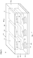
FIG. 5 is a transparent perspective view illustrating, in a partially omitted manner, the storage battery container of the embodiment as viewed from the front; -
FIG. 6 is a transparent perspective view illustrating, in a partially omitted manner, the storage battery container of the embodiment as viewed from the back; -
FIG. 7 is a cross section taken along line VII-VII inFIG. 5 in a partially omitted manner; -
FIG. 8 is a configuration diagram illustrating an air supply portion; and -
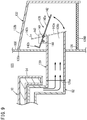
FIG. 9 is a longitudinal section illustrating a configuration of an air exhaust portion. - An embodiment in which the storage battery container of the invention is applied to NaS batteries will be described referring to
FIGS. 1 to 9 . - First, before describing the storage battery container of this embodiment (hereinafter referred to as container 10), a
storage battery 12 that is accommodated in the container 10 (seeFIG. 5 ) will be described referring toFIGS. 1 to 4 . - As shown in
FIG. 1 , thestorage battery 12 includes acasing 18 accommodating abattery assembly 16 formed of a plurality of unit cells 14 (seeFIG. 4 ), and a variableheat dissipation device 22 for maintaining the temperature in thecasing 18 within a certain allowable range (operating temperature range) so as to achieve heat balance of heat accumulation within thecasing 18. Atemperature sensor 26 for measuring the present temperature in thecasing 18 is further provided. The variableheat dissipation device 22 includes a heatdissipation control unit 28 that drives a fan for feeding air into thecasing 18. This will be described later. - Now, a specific example of the
storage battery 12 provided with the variableheat dissipation device 22 will be described referring toFIGS. 2 to 4 . - As shown in
FIG. 2 , thestorage battery 12 includes abase 40 made of, e.g., a steel material, abox 42 placed and fixed on thebase 40, thebattery assembly 16 formed of a large number ofunit cells 14 accommodated in thebox 42, and alid 44 closing the opening of thebox 42. Eachunit cell 14 is made in a cylindrical shape and accommodated within thebox 42 in such a manner that its axial direction extends in a vertical direction. Thebox 42 and thelid 44 form thecasing 18 of thestorage battery 12. - Further,
heaters 24, which are used to raise the temperature in thebox 42, are provided on the bottom surface and inner wall surfaces of thebox 42. Further, the space between thebox 42 and thebattery assembly 16 is filled withsilica sand 46 for the purpose of transmitting heat from theheaters 24 to theunit cells 14 and absorbing heat generated from theunit cells 14. - The
box 42 has a substantially cuboid shape, for example, includes four side walls (afirst side wall 68a, asecond side wall 68b, athird side wall 68c, and afourth side wall 68d: seeFIG. 4 ) and a bottom wall, and has an opening at the top. Thebox 42 is formed of a plate material made of stainless steel, for example, and is shaped like a box having a hollow 48 in itself. The hollow 48 is an enclosed space that is airtightly sealed, and has a structure in which the hollow 48 and the outside space can communicate with each other through a vacuum valve not shown. The hollow 48 is filled with a porous,vacuum insulation board 50 that is made by solidifying glass fiber into a plate-like shape with adhesive, and so thebox 42 has a vacuum heat insulation structure. - The
lid 44 has atop wall 52 and anawning 54, and is placed so as to close the opening at the top of thebox 42. Like thebox 42 described above, thelid 44 is also formed of a plate material made of stainless steel, for example, and is shaped like a box having a hollow 56 in itself. The hollow 56 is an enclosed space that is airtightly sealed, and has a structure in which the hollow 56 and the outside space can communicate with each other through a vacuum valve not shown. The hollow 56 is filled with a porous,vacuum insulation board 58 that is made by solidifying glass fiber into a plate-like shape with adhesive, and so thelid 44 has a vacuum heat insulation structure. - On the other hand, as shown in
FIG. 4 , thebattery assembly 16 is formed of two ormore blocks 64 that are connected in series from a positiveoutside terminal 60 to a negative outsideterminal 62. Eachblock 64 includes two or more circuits (strings 66) connected in parallel, where each of the circuits is formed of two ormore unit cells 14 connected in series. The positiveoutside terminal 60 protrudes outside through thefirst side wall 68a of thebox 42, and the negativeoutside terminal 62 protrudes outside through thesecond side wall 68b of the box 42 (the side wall opposite to thefirst side wall 68a). - Then, as shown in
FIGS. 2 to 3B , the variableheat dissipation device 22 includes ametal duct 72 which is provided at least between thebox 42 and thelid 44 and through whichair 70 flows, aplate member 74 provided between thebattery assembly 16 and theduct 72 and having at least an electric insulating property, and afan 76 provided outside of thebox 42 and feeding theair 70 into theduct 72. - The
duct 72 has anair introduction portion 78 made of metal into which theair 70 is introduced, aheat transport portion 80 made of metal and provided downstream of theair introduction portion 78 between thelid 44 and thebox 42 so as to transport at least the heat generated in thebox 42 together with theair 70, and aheat discharge portion 82 made of metal and provided downstream of theheat transport portion 80 so as to discharge the heat outward together with theair 70. - The
air introduction portion 78 extends along thefirst side wall 68a of thebox 42 into the space between theawning 54 of thelid 44 and thefirst side wall 68a of thebox 42. In particular, a cushioning member 84 (heat insulator) is interposed between theair introduction portion 78 and thefirst side wall 68a of thebox 42, so that theair introduction portion 78 is spaced apart from thefirst side wall 68a of thebox 42. Preferably, the cushioningmember 84 has a heat insulating function, and a heat insulator is used in this embodiment. - The
air introduction portion 78 includes anair feed portion 86 into which theair 70 is fed from thefan 76 provided outside, and anair guide portion 88 communicating with theair feed portion 86, and guiding theair 70 fed into theair feed portion 86 to theheat transport portion 80. Theair feed portion 86 has anair chamber 90. A duct in theair chamber 90 has a shape that gradually expands toward theair guide portion 88. - On the other hand, as shown in
FIG. 3A , theheat transport portion 80 is provided between thetop wall 52 of thelid 44 and thebox 42. Alower surface 80a of theheat transport portion 80 is formed in a rectangular shape that is the same as the shape of the opening of thebox 42, and the size of thelower surface 80a is substantially the same as the size of the opening of thebox 42. Further, thelower surface 80a of the heat transport portion 80 (the surface facing the battery assembly 16 (or the plate member 74)) is provided with a plurality offins 92 extending toward the battery assembly 16 (or toward the plate member 74)). - As shown in
FIG. 3B , aduct 94 in theheat transport portion 80 has formed therein a plurality ofsupports 96 for maintaining the shape of theduct 94. The supports 96 can be of plate-like shape, corrugated shape, or piece-like shape. - As shown in
FIGS. 2 and3A , theheat discharge portion 82 is provided to extend along thesecond side wall 68b of thebox 42 from the space between thesecond side wall 68b of thebox 42 and theawning 54 of thelid 44, and is particularly in contact with thesecond side wall 68b of thebox 42. - Then, the heat
dissipation control unit 28 of the variableheat dissipation device 22 drives thefan 76, whereby the cooledair 70 is supplied into theduct 72 as thefan 76 operates. As theair 70 is supplied into theduct 72, the heat in thebox 42 is transferred to theair 70 in theheat transport portion 80 and raises the temperature of theair 70. The temperature-raisedair 70 is discharged to the outside of thebox 42 through theheat discharge portion 82. That is, the heat in the interior of thecasing 18 is dissipated. This forcibly cools the interior of thecasing 18, and the interior of thecasing 18 is efficiently cooled even if thebox 42 and thelid 44 both have a highly heat-insulated structure. As a result, the temperature in thecasing 18 can be maintained within an allowable range even if the discharge output is high or lasts for a long time, which enables thebattery assembly 16 inside thebox 42 to operate in an optimum operating environment. - Next, the
container 10 of the embodiment will be described referring toFIGS. 5 to 9 . - The
container 10 includes acontainer body 112 having atop surface 102, abottom surface 104, and four side surfaces (afront surface 106, arear surface 108, aright side surface 110a, and aleft side surface 110b), and thecontainer 10 accommodates a plurality ofstorage batteries 12.FIG. 5 shows an example in which threestorage batteries 12 are arranged side by side on the upper stage and threestorage batteries 12 are arranged side by side on the lower stage, with two of thestorage batteries 12 being disposed in each vertical row. - The
container 10 includes:air supply portions 116 each having anair inlet port 114 formed in thebottom surface 104; the variableheat dissipation devices 22 described above; andair exhaust portions 120 provided at therear surface 108 to respectively face theheat discharge portions 82 of the variableheat dissipation devices 22. Threeair supply portions 116 are provided in correspondence with the number of the vertical rows, and sixair exhaust portions 120 are provided in correspondence with the number of thestorage batteries 12. - Each
air supply portion 116 places theair inlet port 114 in an opened state when electric power is being supplied, and places theair inlet port 114 in a closed state when the supply of electric power is stopped. For example, as shown inFIG. 8 , eachair supply potion 116 includes an opening/closing lid 122 and anelectromagnetic chuck 124 that electromagnetically holds the opening/closing lid 122 when supplied with electric power, to thereby place theair inlet port 114 in the opened state. When the supply of electric power to theelectromagnetic chuck 124 is stopped, theair inlet port 114 is closed due to the weight of the opening/closing lid 122 itself. It is preferred that theair inlet port 114 is provided with afirst filter 126A for preventing entry of dust. In this case, it is preferred that thefirst filter 126A is a filter made of uninflammable nonwoven fabric, for example. - Each
air exhaust portion 120 places the air exhaust port 136 (seeFIG. 9 ) in substantially an opened state when the corresponding variable heat dissipation device 22 (seeFIG. 1 ) is driven, and places theair exhaust port 136 in substantially a closed state when the variableheat dissipation device 22 is stopped. For example, as shown inFIG. 9 , theair exhaust portion 120 includes atube 130 that has oneopening 128a and anotheropening 128b and that is arranged so that its center axis extends in substantially a horizontal direction, and ahood 132 for protecting theother opening 128b side of thetube 130. - The one
opening 128a of thetube 130 is disposed in the interior of thecontainer body 112 on the inside of therear surface 108 of thecontainer body 112, and theother opening 128b of thetube 130 is positioned on the outside of therear surface 108 of thecontainer 10. - The
hood 132 has its openingend 132a fixed to therear surface 108 among the side surfaces of thecontainer body 112, and its top 132b inclined downward toward the rear. Thehood 132 functions also as a protection from rainwater. Thehood 132 has an opening formed at the bottom, and this opening constitutes theair exhaust port 136. Theair exhaust port 136 discharges the air substantially downward. That is, thetube 130 is arranged so that its center axis extends in substantially the horizontal direction and the direction of exhaust from theair exhaust port 136 is substantially downward, so that the air is exhausted horizontally and then downward. It is preferred that theair exhaust port 136 is provided with asecond filter 126B for preventing entry of dust. In this case, too, thesecond filer 126B is preferably a filter made of uninflammable nonwoven fabric, for example. - The
tube 130 is further provided with ashutter 138 that opens and closes theother opening 128b. Theshutter 138 includes arotary shaft 140 and arotary plate 142 that are provided within thehood 132 at the upper part of thetube 130 in a position closer to thisother opening 128b. Therotary shaft 140 is rotatably supported by a pair of mountingplates 143 fixed on thetube 130. - The
rotary plate 142 is formed by bending a piece of metal plate and has a substantially L-shaped cross section. That is, therotary plate 142 has a structure in which afirst plate portion 142a with a large area and asecond plate portion 142b with a small area are integrally formed, and thefirst plate portion 142a and thesecond plate portion 142b form an angle from 85 to 95 degrees, for example. - The
rotary plate 142 is rotatably attached to therotary shaft 140, whereby, in a natural state (when thefan 76 is not being driven), the plate surface of thefirst plate portion 142a is positioned to close theother opening 128b of thetube 130, and thesecond plate portion 142b is positioned so as to protrude toward the top 132b of thehood 132. - Consequently, the
rotary plate 142 is turned in one direction around therotary shaft 140 by the wind pressure that is produced by the discharge of heat from the variableheat dissipation device 22 when thefan 76 is driven. That is, the entirety of therotary plate 142 turns in such a direction that thefirst plate portion 142a separates away from theother opening 128b of thetube 130. Then, the heat from the variableheat dissipation device 22 is discharged through thetube 130, thehood 132, and thesecond filter 126B. That is, theair exhaust port 136 is placed in the opened state. - Further, the
first plate portion 142a and thesecond plate portion 142b of therotary plate 142 function also as a weight for adjusting the turning of therotary plate 142 in that one direction. That is, thesecond plate portion 142b restricts therotary plate 142 so that it does not turn in the one direction with a wind pressure that is smaller than the wind pressure produced by the heat discharge from the variableheat dissipation device 22. The mountingplates 143 may be provided with astopper 144 so as to prevent therotary plate 142 from turning excessively. - That is, in the natural state, the
first plate portion 142a of therotary plate 142 is almost hanging down and thereby substantially closes theair exhaust port 136. As thefan 76 is driven, the wind pressure produced by the heat discharge from the variableheat dissipation device 22 turns therotary plate 142 in the one direction, allowing the heat from the variableheat dissipation device 22 to be discharged from theair exhaust port 136. - Next, functions of the
container 10 of the embodiment will be described. - First, in a normal state, electric power is being supplied to the
container 10, so that theelectromagnetic chucks 124 operate in the respectiveair supply portions 116 to hold the opening/closinglids 122 in the opened state. That is, theair inlet ports 114 are normally opened. - In this normal state, if the variable
heat dissipation device 22 of onestorage battery 12 drives thefan 76, then, as thefan 76 starts, theair 70 introduced from theair inlet ports 114 is supplied into theduct 72 of thisstorage battery 12. As theair 70 is supplied into theduct 72, the heat in thebox 42 is transferred to theair 70 in theheat transport portion 80 and raises the temperature of theair 70. The temperature-raisedair 70 is discharged to the outside of thebox 42 through theheat discharge portion 82. That is, the heat in the interior of thecasing 18 is dissipated. This forcibly cools the interior of thecasing 18, and the interior of thecasing 18 is thus efficiently cooled even if thebox 42 and thelid 44 both have a highly heat-insulated structure. As a result, the temperature in thecasing 18 can be maintained within an allowable range even if the discharge output is high or lasts for a long time, which enables thebattery assembly 16 inside thebox 42 to operate in an optimum operating environment. - Then, the
air 70 discharged from the heat discharge portion 82 (temperature-raised air) is sent toward therear surface 108 side of thecontainer body 112 by the wind pressure from thefan 76. In particular, in this embodiment, since theair exhaust portion 120 is disposed opposite to theheat discharge portion 82, the wind pressure of theair 70 discharged from theheat discharge portion 82 causes therotary plate 142 of theair exhaust portion 120 to turn in the one direction. As a result, the dischargedair 70 is introduced into thetube 130 through the oneopening 128a of thetube 130, further passes through thetube 130, and is exhausted from the other opening (air exhaust port 136). - In the
air exhaust portion 120 that corresponds to thestorage battery 12 whose variableheat dissipation device 22 is not operating, theair 70 is not discharged from theheat discharge portion 82 and therefore therotary plate 142 of theair exhaust portion 120 is maintained in the natural state. Then, the air entering from the openedair inlet ports 114 presses therotary plate 142, but this is not forced introduction of air by thefan 76, and so the wind pressure against thefirst plate portion 142a of therotary plate 142 of theair exhaust portion 120 is small. Accordingly, the weight of thesecond plate portion 142b prevents therotary plate 142 from turning. That is, thefirst plate portion 142a is kept in the hanging down state. Theair exhaust port 136 is thus kept in substantially the closed state. In this case, it is possible to maintain the closed state of theair exhaust port 136 without using electric power. - In this way, waste heat in each
storage battery 12 can be exhausted directly through theair exhaust port 136 of theair exhaust portion 120 using theair 70 that is introduced from theair inlet ports 114 formed in thebottom surface 104 of thecontainer body 112, and therefore the waste heat is not exhausted into the interior of thecontainer body 112 from thestorage batteries 12. That is, the amount of heat discharged into the interior of thecontainer body 112 is unchanged irrespective of whether the variableheat dissipation devices 22 are being driven or stopped. As a result, in normal operation, a control to adjust the heat balance of thestorage batteries 12 by the variableheat dissipation devices 22 can be made easy. Furthermore, the installation of thefirst filters 126A in theair inlet ports 114 makes it possible to avoid entry of dust, sand, etc. into thecontainer body 112. - Next, if the supply of electric power to the
container 10 is stopped due to maintenance work or emergency stop, the operation of theelectromagnetic chucks 124 to hold the opening/closinglids 122 stops in theair supply portions 116. Accordingly, the opening/closinglids 122 close the correspondingair inlet ports 114 due to their own weights and keep them normally closed. - In each
air exhaust portion 120, since the supply of electric power to the variableheat dissipation device 22 stops, therotary plate 142 keeps the substantially hanging down state as explained above, thereby substantially keeping theair exhaust port 136 normally closed. - As a result, it is possible to confine the gas that contains active materials, for example, within the
container 10 without supplying electric power from a battery, for example. This reduces the electric power that is required for the next operation and improves the operating efficiency. Furthermore, for example, there is no need to provide units for electrically opening and closing theair inlet ports 114 and theair exhaust ports 136, leading to simplification of the structure and reduced power consumption. - Further, because the flow passage of the exhaust is directed from a horizontal direction to a downward direction, it is possible to prevent dust, sand, etc. from directly entering the
tube 130. Moreover, the installation of thesecond filters 126B in theair exhaust ports 136 further avoids entry of dust, sand, etc. - The embodiments described above can be summarized as follows.
- [1] A storage battery container (10) has at least a top surface (102), a bottom surface (104), and a side surface (106, 108, 110a, 110b) and accommodates a plurality of storage batteries (12). The storage battery container (10) includes: air supply portions (116) each including an air inlet port (114) provided in the bottom surface (104); variable heat dissipation devices (22) provided respectively for the storage batteries (12), each of the variable heat dissipation devices (22) being configured to, when being driven, introduce air from the air supply portions (116) into the storage battery (12) and discharge heat in the storage battery (12) together with the air so as to achieve heat balance of heat accumulation in the storage battery (12); and air exhaust portions (120) provided on the side surface respectively in correspondence with heat discharge portions (82) of the variable heat dissipation devices (22) and each including an air exhaust port (136). Each of the air supply portions (116) places the air inlet port (114) in an opened state when supplied with electric power, and places the air inlet port (114) in a closed state when the supply of electric power is stopped, and each of the air exhaust portions (120) places the air exhaust port (136) in an opened state when the corresponding variable heat dissipation device (22) is driven, and places the air exhaust port (136) in a closed state when the variable heat dissipation device (22) is stopped.
First, in a normal state, the container (10) is supplied with electric power and therefore the air inlet ports (114) of the air supply portions (116) are opened. In this normal state, when the variable heat dissipation device (22) of one storage battery (12) is driven, then the air exhaust port (136) of the air exhaust portion (120) that faces the variable heat dissipation device (22) of this storage battery (12) is opened. That is, the heat in this storage battery (12) is dissipated.
In this way, waste heat in each storage battery (12) can be exhausted directly through the air exhaust port (136) of the air exhaust portion (120) using the air that is introduced from the air inlet ports (114), and therefore the waste heat is not discharged into the interior of the container (10) from the storage batteries (12). That is, the amount of heat discharged into the interior of the container (10) is unchanged irrespective of whether the variable heat dissipation devices (22) are being driven or stopped. As a result, in normal operation, a control to adjust the heat balance of the storage batteries (12) by the variable heat dissipation devices (22) can be made easy.
On the other hand, when the supply of electric power to the container (10) is stopped, the air inlet ports (114) of the air supply portions (116) are closed. Further, since the variable heat dissipation devices (22) are stopped, the air exhaust ports (136) of the air exhaust portions (120) provided to face the variable heat dissipation devices (22) are also closed. That is, it is possible to confine the gas that contains active materials, for example, within the container (10) without supplying electric power from a battery, for example. This reduces the electric power that is required for the next operation and improves the operating efficiency. Furthermore, for example, there is no need to provide units for electrically opening and closing the air exhaust ports (136), leading to simplification of the structure and reduced power consumption. - [2] In the embodiment, the air supply portions (116) may each include an opening/closing lid (122) that closes the air inlet port (114) by its own weight when the supply of electric power is stopped.
- [3] In the embodiment, the air supply portions (116) may each hold the opening/closing lid (122) when supplied with electric power, to thereby place the air inlet port (114) in the opened state. In this case, the opening/closing lid (122) may be held electromagnetically. The opening/closing lid (122) is held to place the air inlet port (114) in the opened state when the container (10) is supplied with electric power. Air outside of the container (10) can thus be introduced into the interior of the container (10) through the air inlet ports (114).
- [4] In the embodiment, the air inlet ports (114) may each be provided with a filter (126A) for preventing entry of dust. It is then possible to avoid entry of dust, sand, etc. into the container (10) through the air inlet ports (114) .
- [5] In the embodiment, the air exhaust portions (120) each include a tube (130) having one opening (128a) disposed corresponding to the heat discharge portion (82) of the corresponding variable heat dissipation device (22) and the other opening (128b) disposed outside of the side surface, and the direction of exhaust through the tube (130) is horizontal and the direction of exhaust through the air exhaust port (136) is downward.
When the variable heat dissipation device (22) is driven, air is supplied into the storage battery (12) and the heat in the storage battery (12) is transferred to the air and raises the temperature of the air. The temperature-raised air is discharged out of the storage battery (12) through the heat discharge portion (82). That is, the heat in the storage battery (12) is dissipated. The air discharged from the heat discharge portion (82) enters the air exhaust portion (120) through one opening (128a) facing the heat discharge portion (82) and is discharged through the air exhaust port (136) provided on the outside of the side surface of the container (10).
Further, since the exhaust through the air exhaust port (136) is directed downward, it is possible to prevent entry of dust, sand, etc. into the container (10) directly through the tube (130). - [6] In the embodiment, the air exhaust portions (120) may each include a rotary shaft (140) and a rotary plate (142) that are attached to the tube (130) in a position closer to the other opening (128b), and the rotary plate (142) may be turned in one direction around the rotary shaft (140) by a wind pressure that is produced as the corresponding variable heat dissipation device (22) discharges the heat when the variable heat dissipation device (22) is driven, to thereby place the air exhaust port (136) in the opened state.
The air discharged from the heat discharge portion (82) (air with a raised temperature) is sent toward the side surface of the container (10) by the variable heat dissipation device (22) being driven. In particular, since the air exhaust portion (120) is provided in correspondence with the heat discharge portion (82), the rotary plate (142) of the air exhaust portion (120) is turned in one direction by the wind pressure of the air discharged from the heat discharge portion (82). As a result, the discharged air is introduced into the tube (130) and further passes through the flow passage in the tube (130) and is discharged from the air exhaust port (136).
On the other hand, in the air exhaust portion (120) corresponding to the storage battery (12) whose variable heat dissipation device (22) is not being driven, air is not discharged from the heat discharge portion (82) and therefore the rotary plate (142) of the air exhaust portion (120) maintains its natural state and the air exhaust port (136) maintains the closed state. - [7] In the embodiment, preferably, the air exhaust portions (120) each include a weight provided for the rotary plate (142) to adjust at least the turning of the rotary plate (142) in the one direction.
In the air exhaust portion (120) corresponding to the storage battery (12) whose variable heat dissipation device (22) is not being driven, air is not discharged from the heat discharge portion (82) and therefore the rotary plate (142) of the air exhaust portion (120) maintains the natural state. Then, air entering from the opened air exhaust port (136) presses the rotary plate (142), but this is not forced introduction of air by the variable heat dissipation device (22), and so the wind pressure against the rotary plate (142) of the air exhaust portion (120) is small. Accordingly, the weight prevents the rotary plate (142) from turning. That is, the air exhaust port (136) is closed by the rotary plate (142). It is therefore possible to maintain the closed state of the air exhaust port (136) without using electric power. In this case, the rotary plate (142) itself may constitute the weight, or a separate weight may be attached to the rotary plate (142). - [8] In the embodiment, the air exhaust ports (136) may each be provided with a filter (126B) for preventing entry of dust. It is thus possible to further effectively avoid entry of dust, sand, etc.
- [9] In the embodiment, at least a portion of the tube (130) where the rotary shaft (140) and the rotary plate (142) are provided may be covered by a hood (132), and the air exhaust port (136) may be provided in a lower part of the hood (132). When electric power is not supplied to the container (10), for example, dust, sand, etc. may enter the tube (130) together with air from the outside of the container (10). However, the hood (132) protects the rotary plate (142) of the air exhaust portion (120), thereby preventing dust, sand, raindrops, etc. from directly entering the container (10).
- In the examples described above, three
air supply portions 116 are provided in correspondence with the number of the vertical rows of thestorage batteries 12, but one air supply portion or four or more air supply portions may be provided independently of the number of the vertical rows. - The storage battery container of the present invention is not limited to the embodiments described above but can of course adopt various configurations without departing from the essence and gist of the invention. For instance, in the examples above, both the
box 42 and thelid 44 have a vacuum heat insulation structure, but thebox 42 and thelid 44 may both be an air heat insulation structure. Needless to say, thelid 44 may be an air heat insulation structure and thebox 42 may be a vacuum heat insulation structure, or thelid 44 may be a vacuum heat insulation structure and thebox 42 may be an air heat insulation structure.
Claims (9)
- A storage battery container (10) including at least a top surface (102), a bottom surface (104), and a side surface (106, 108, 110a, 110b), and accommodating a plurality of storage batteries (12), the storage battery container (10) comprising:an air supply portion (116) including an air inlet port (114) provided in the bottom surface (104);a variable heat dissipation device (22) provided for each of the storage batteries (12) and configured to, when being driven, introduce air from the air supply portion (116) into the storage battery (12) and discharge heat in the storage battery (12) together with the air so as to achieve heat balance of heat accumulation in the storage battery (12); andan air exhaust portion (120) provided on the side surface in correspondence with a heat discharge portion (82) of the variable heat dissipation device (22) and including an air exhaust port (136),wherein the air supply portion (116) places the air inlet port (114) in an opened state when supplied with electric power, and places the air inlet port (114) in a closed state when the supply of electric power is stopped, andthe air exhaust portion (120) places the air exhaust port (136) in an opened state when the variable heat dissipation device (22) is driven, and places the air exhaust port (136) in a closed state when the variable heat dissipation device (22) is stopped.
- The storage battery container (10) according to claim 1, wherein the air supply portion (116) includes an opening/closing lid (122) configured to close the air inlet port (114) by an own weight thereof when the supply of electric power is stopped.
- The storage battery container (10) according to claim 2, wherein the air supply portion (116) holds the opening/closing lid (122) when supplied with electric power, to thereby place the air inlet port (114) in the opened state.
- The storage battery container (10) according to any one of claims 1 to 3, wherein the air inlet port (114) is provided with a filter (126A) configured to prevent entry of dust.
- The storage battery container (10) according to any one of claims 1 to 4, wherein
the air exhaust portion (120) includes a tube (130) having one opening (128a) disposed corresponding to the heat discharge portion (82) of the variable heat dissipation device (22) and another opening (128b) disposed outside of the side surface (108), and
a direction of exhaust through the tube (130) is horizontal and a direction of exhaust through the air exhaust port (136) is downward. - The storage battery container (10) according to claim 5, wherein
the air exhaust portion (120) includes a rotary shaft (140) and a rotary plate (142) that are attached to the tube (130) in a position closer to the another opening (128b), and
the rotary plate (142) is turned in one direction around the rotary shaft (140) by a wind pressure that is produced as the variable heat dissipation device (22) discharges the heat when the variable heat dissipation device (22) is driven, to thereby place the air exhaust port (136) into the opened state. - The storage battery container (10) according to claim 6, wherein the air exhaust portion (120) includes a weight provided for the rotary plate (142) to adjust at least the turning of the rotary plate (142) in the one direction.
- The storage battery container (10) according to any one of claims 5 to 7, wherein the air exhaust port (136) is provided with a filter (126B) configured to prevent entry of dust.
- The storage battery container (10) according to claim 6, wherein
at least a portion of the tube (130) where the rotary shaft (140) and the rotary plate (142) are provided is covered by a hood (132), and
the air exhaust port (136) is provided in a lower part of the hood (132).
Applications Claiming Priority (2)
| Application Number | Priority Date | Filing Date | Title |
|---|---|---|---|
| JP2019047237 | 2019-03-14 | ||
| PCT/JP2020/009159 WO2020184332A1 (en) | 2019-03-14 | 2020-03-04 | Storage battery container |
Publications (2)
| Publication Number | Publication Date |
|---|---|
| EP3799188A1 true EP3799188A1 (en) | 2021-03-31 |
| EP3799188A4 EP3799188A4 (en) | 2022-03-16 |
Family
ID=72426442
Family Applications (1)
| Application Number | Title | Priority Date | Filing Date |
|---|---|---|---|
| EP20771076.5A Pending EP3799188A4 (en) | 2019-03-14 | 2020-03-04 | BATTERY HOLDER |
Country Status (5)
| Country | Link |
|---|---|
| US (1) | US11728536B2 (en) |
| EP (1) | EP3799188A4 (en) |
| JP (1) | JP6936923B2 (en) |
| KR (1) | KR102566660B1 (en) |
| WO (1) | WO2020184332A1 (en) |
Cited By (2)
| Publication number | Priority date | Publication date | Assignee | Title |
|---|---|---|---|---|
| RU232179U1 (en) * | 2024-04-26 | 2025-02-28 | Публичное акционерное Общество "Энергия" (ПАО "Энергия") | STREET CLIMATE CONTROLLED BATTERY |
| EP4542729A1 (en) * | 2023-10-17 | 2025-04-23 | Purem GmbH | Battery system |
Families Citing this family (4)
| Publication number | Priority date | Publication date | Assignee | Title |
|---|---|---|---|---|
| CN112968245B (en) * | 2021-02-02 | 2023-02-03 | 上海派能能源科技股份有限公司 | Energy storage system heat dissipation device and heat dissipation method thereof |
| JP2023010129A (en) * | 2021-07-09 | 2023-01-20 | 株式会社日立製作所 | Power storage device for moving body and cooling method thereof |
| CN115207518B (en) * | 2022-09-14 | 2022-11-22 | 惠州市纬世新能源有限公司 | High-rate lithium ion battery cell based on heat radiation structure |
| CN117200022A (en) * | 2023-08-02 | 2023-12-08 | 江门劳士国际电气有限公司 | A method of constructing an exhaust channel for a power box and its power box |
Family Cites Families (13)
| Publication number | Priority date | Publication date | Assignee | Title |
|---|---|---|---|---|
| JP4543464B2 (en) * | 1999-12-09 | 2010-09-15 | トヨタ自動車株式会社 | Battery pack |
| JP5080829B2 (en) | 2007-03-08 | 2012-11-21 | 日本碍子株式会社 | Package for sodium-sulfur battery |
| EP2383825B1 (en) * | 2009-12-03 | 2013-08-07 | Panasonic Corporation | Fuel cell system and maintenance method for fuel cell system |
| JP2011249081A (en) * | 2010-05-25 | 2011-12-08 | Panasonic Corp | Stationary power storage apparatus |
| JP5464168B2 (en) * | 2010-06-04 | 2014-04-09 | 株式会社デンソー | Power supply |
| JP4918611B1 (en) * | 2010-11-09 | 2012-04-18 | 三菱重工業株式会社 | Battery system |
| EP2672563B1 (en) * | 2011-02-03 | 2018-02-21 | NGK Insulators, Ltd. | Battery housing structure |
| JP2012175874A (en) * | 2011-02-24 | 2012-09-10 | Fujitsu Ltd | Uninterruptible power supply device, and information processing system having the same |
| EP2808934B1 (en) * | 2012-01-24 | 2017-04-12 | NGK Insulators, Ltd. | Power storage apparatus and method of operating power storage apparatus |
| WO2015029567A1 (en) | 2013-08-26 | 2015-03-05 | 日本碍子株式会社 | Exhaust processing device and containing device |
| JP6391583B2 (en) | 2013-10-17 | 2018-09-19 | 日本碍子株式会社 | Secondary battery |
| DE102014221684A1 (en) * | 2014-07-11 | 2016-01-14 | Robert Bosch Gmbh | Housing for receiving a plurality of battery cells with a cooling device integrated in the housing |
| JP6400464B2 (en) * | 2014-12-24 | 2018-10-03 | 株式会社東芝 | Battery device |
-
2020
- 2020-03-04 WO PCT/JP2020/009159 patent/WO2020184332A1/en not_active Ceased
- 2020-03-04 JP JP2020542184A patent/JP6936923B2/en active Active
- 2020-03-04 EP EP20771076.5A patent/EP3799188A4/en active Pending
- 2020-03-04 KR KR1020207037830A patent/KR102566660B1/en active Active
- 2020-12-21 US US17/128,425 patent/US11728536B2/en active Active
Cited By (2)
| Publication number | Priority date | Publication date | Assignee | Title |
|---|---|---|---|---|
| EP4542729A1 (en) * | 2023-10-17 | 2025-04-23 | Purem GmbH | Battery system |
| RU232179U1 (en) * | 2024-04-26 | 2025-02-28 | Публичное акционерное Общество "Энергия" (ПАО "Энергия") | STREET CLIMATE CONTROLLED BATTERY |
Also Published As
| Publication number | Publication date |
|---|---|
| JPWO2020184332A1 (en) | 2021-03-18 |
| US11728536B2 (en) | 2023-08-15 |
| EP3799188A4 (en) | 2022-03-16 |
| US20210111449A1 (en) | 2021-04-15 |
| JP6936923B2 (en) | 2021-09-22 |
| KR20210015941A (en) | 2021-02-10 |
| KR102566660B1 (en) | 2023-08-11 |
| WO2020184332A1 (en) | 2020-09-17 |
Similar Documents
| Publication | Publication Date | Title |
|---|---|---|
| US11728536B2 (en) | Storage battery container | |
| KR102390607B1 (en) | Method and apparatus for managing thermal runaway gases in battery systems | |
| KR102665192B1 (en) | Battery pack and device including the same | |
| KR102922132B1 (en) | Battery pack and device including the same | |
| EP4019094A1 (en) | Battery module, battery rack, and power storage device | |
| JP6157627B2 (en) | Containment device | |
| CN218548570U (en) | Battery assembly | |
| CN114175356B (en) | Energy storage devices | |
| CN220604897U (en) | Batteries and electrical devices | |
| US20240204347A1 (en) | Battery device | |
| CN113054300A (en) | Battery thermal runaway heat exchange structure, battery assembly and vehicle | |
| EP4708594A1 (en) | Energy storage apparatus | |
| CN212751901U (en) | Container type energy storage system | |
| CN219226531U (en) | Battery pack box, battery pack and electronic equipment | |
| JP5853195B2 (en) | Power storage device | |
| JP2024541926A (en) | Battery pack and automobile including same | |
| JP2018106948A (en) | Rechargeable battery board and battery pack | |
| CN222966237U (en) | Energy storage container and energy storage system | |
| JP5870290B2 (en) | Power storage device | |
| CN218887446U (en) | Battery pack and power device | |
| JP2025511663A (en) | Battery pack | |
| CN116365135A (en) | A battery box, an energy storage group and an energy storage unit | |
| WO2023006725A1 (en) | Electrochemical energy storage device | |
| KR102042381B1 (en) | Heat dissipating case of energy storage apparatus | |
| CN222261175U (en) | Energy storage container and energy storage system |
Legal Events
| Date | Code | Title | Description |
|---|---|---|---|
| STAA | Information on the status of an ep patent application or granted ep patent |
Free format text: STATUS: THE INTERNATIONAL PUBLICATION HAS BEEN MADE |
|
| PUAI | Public reference made under article 153(3) epc to a published international application that has entered the european phase |
Free format text: ORIGINAL CODE: 0009012 |
|
| STAA | Information on the status of an ep patent application or granted ep patent |
Free format text: STATUS: REQUEST FOR EXAMINATION WAS MADE |
|
| 17P | Request for examination filed |
Effective date: 20201224 |
|
| AK | Designated contracting states |
Kind code of ref document: A1 Designated state(s): AL AT BE BG CH CY CZ DE DK EE ES FI FR GB GR HR HU IE IS IT LI LT LU LV MC MK MT NL NO PL PT RO RS SE SI SK SM TR |
|
| AX | Request for extension of the european patent |
Extension state: BA ME |
|
| REG | Reference to a national code |
Ref country code: DE Ref legal event code: R079 Free format text: PREVIOUS MAIN CLASS: H01M0010390000 Ipc: H01M0010627000 |
|
| A4 | Supplementary search report drawn up and despatched |
Effective date: 20220216 |
|
| RIC1 | Information provided on ipc code assigned before grant |
Ipc: H01M 10/653 20140101ALN20220210BHEP Ipc: H01M 10/6571 20140101ALN20220210BHEP Ipc: H01M 10/658 20140101ALN20220210BHEP Ipc: H01M 10/39 20060101ALN20220210BHEP Ipc: H01M 10/63 20140101ALI20220210BHEP Ipc: H01M 10/617 20140101ALI20220210BHEP Ipc: H01M 50/204 20210101ALI20220210BHEP Ipc: H01M 50/253 20210101ALI20220210BHEP Ipc: H01M 10/6566 20140101ALI20220210BHEP Ipc: H01M 10/6563 20140101ALI20220210BHEP Ipc: H01M 10/6556 20140101ALI20220210BHEP Ipc: H01M 10/627 20140101AFI20220210BHEP |
|
| DAV | Request for validation of the european patent (deleted) | ||
| DAX | Request for extension of the european patent (deleted) | ||
| STAA | Information on the status of an ep patent application or granted ep patent |
Free format text: STATUS: EXAMINATION IS IN PROGRESS |
|
| 17Q | First examination report despatched |
Effective date: 20241212 |